

Page 1
C3902M-EN (02/12)
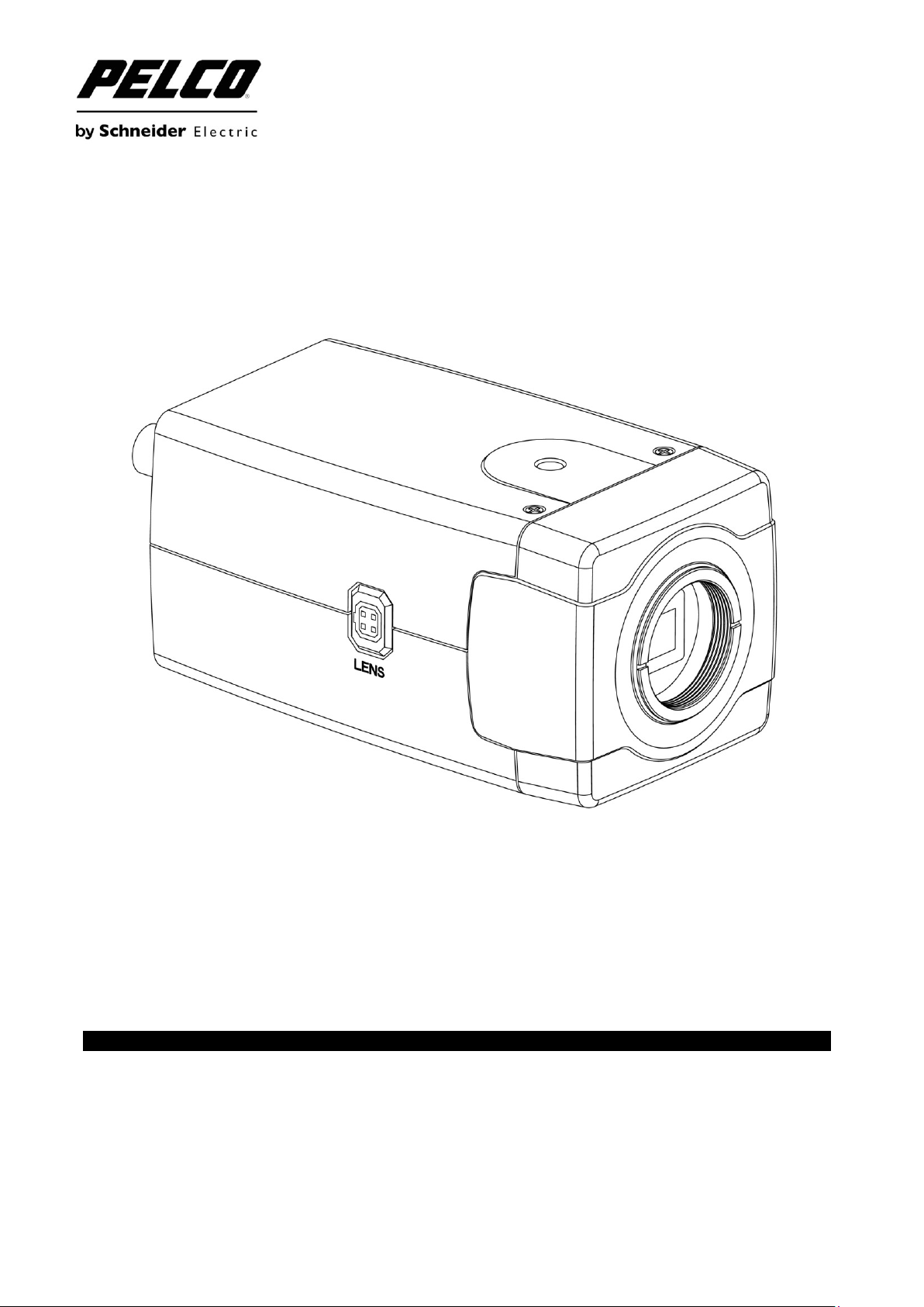
C20-CH Series 650 TV lines
High Resolution Camera
Installation/Operation Manual
Before attempting to connect or operate this product, please read these instructions
carefully and save this manual for future use.
1
Page 2

CONTENTS
CONTENTS
Important Safety Instructions ........................................................................................................................ 3
Troubleshooting Tips ..................................................................................................................................... 4
Regulatory Notices ........................................................................................................................................ 5
1. Introduction ................................................................................................................................................ 6
2. Part Names and Locations ........................................................................................................................ 7
3. OSD Menu ............................................................................................................................................... 10
4. OSD Menu Settings ................................................................................................................................ 11
4.1 LENS .............................................................................................................................................. 12
4.2 SHUTTER/AGC ............................................................................................................................. 12
4.3 WHITE BAL .................................................................................................................................... 13
4.4 BACKLIGHT ................................................................................................................................... 14
4.5 PICTURE ADJUST ........................................................................................................................ 14
4.6 ATR* ............................................................................................................................................... 14
4.7 MOTION DET................................................................................................................................. 14
4.8 PRIVACY ....................................................................................................................................... 15
4.9 DAY/NIGHT .................................................................................................................................... 15
4.10 NR ................................................................................................................................................ 15
4.11 CAMERA ID ................................................................................................................................. 16
4.12 SYNC ........................................................................................................................................... 16
4.13 LANGUAGE ................................................................................................................................. 16
4.14 CAMERA RESET ......................................................................................................................... 16
4.15 SAVE ALL .................................................................................................................................... 16
5. Specification ............................................................................................................................................ 17
PRODUCT WARRANTY AND RETURN INFORMATION ......................................................................... 18
2
C3902M-EN (02/1 2)
Page 3

Important Safeguards and Warnings
Important Safety Instructions
1. Read Instructions. All the safety and operating instructions should be read before the camera is
operated.
2. Retain Instructions. The safety and operating instructions should be retained for future reference.
3. Heed Warnings. All warnings on the camera and in the operating instructions should be adhered to.
4. Follow Instructions. All operating and use instructions should be followed.
5. Cleaning: Unplug the power unit from the wall outlet before cleaning. Do not use liquid cleaners or
aerosol cleaners. Use a damp cloth for cleaning.
6. Attachments: Do not use attachments not recommended by your appliance dealer, as they may cause
hazards.
7. Water and Moisture: Do not use the camera in any location in which it may be exposed to water or
moisture. (For example, dripping, splashing, or liquid near equipment etc.)
8. Accessories: Do not place the camera on an unstable cart, stand, tripod,
bracket, or table. The camera may fall, causing serious injury to a child or adult,
and serious damage to the camera. Use only with mounting accessories
recommended by your appliance dealer or sold with the camera. Any mounting
of the camera should follow your appliance dealer's instructions.
The camera must be installed in a location or on a piece of equipment that can
withstand three times the total weight of the camera, including the lens, camera,
mount, adapter, etc.
9. Any appliance and cart combination should be moved with care. Quick stops, excessive force, and
uneven surfaces may cause the appliance and cart combination to overturn.
10. Ventilation: The camera should never be placed near or over a radiator or heat register. The camera
should not be placed in a built-in installation such as a bookcase or rack unless proper ventilation is
provided or your appliance dealer's instructions have been adhered to.
11. Power Sources: The camera should be operated only from the type of power source indicated on the
rating plate. If you are not sure of the type of power supply for your installation site, consult your
appliance dealer or local power company.
12. Power Cord Protection: Power supply cords should be routed so that they are not likely to be walked on
or pinched by items placed upon or against them, paying particular attention to cords at plugs,
convenience receptacles, and the point where they exit from the camera.
13. Lightning: For added protection for the camera during a lightning storm, or when it is left unattended and
unused for long periods of time, unplug it from the wall outlet and disconnect the cable system. This will
prevent damage to the camera due to lightning and power line surges.
14. Overloading: Do not overload the wall outlet and extension cord, as this can result in a risk of fire or
electric shock.
15. Object and Liquid Entry: Never push objects of any kind into the camera through openings, as they may
touch dangerous voltage points or short out parts that could result in a fire or electric shock. Never spill
liquid of any kind on the camera.
16. Servicing: Do not attempt to service the camera yourself, as opening or removing covers may expose
you to dangerous voltage or other hazards. Refer all servicing to qualified service personnel.
3
C3902M-EN (02/1 2)
Page 4

Important Safeguards and Warnings
17. Damage Requiring Service: Unplug the power unit from the wall outlet. Refer servicing to qualified
service personnel under the following conditions.
a. When the power supply cord or plug is damaged.
b. If liquid has been spilled or objects have fallen into the camera.
c. If the camera has been exposed to rain or water.
d. If the camera does not operate normally by following the operating instructions. Adjust only those
controls that are covered by the operating instructions, as an improper adjustment of other controls
may result in damage and will often require extensive work by a qualified technician to restore the
camera to its normal operation.
e. If the camera has been dropped or the cabinet has been damaged.
f. When the camera exhibits a distinct change in performance. This indicates a need for service.
18. Replacement Parts: When replacement parts are required, be sure the service technician has used
replacement parts specified by a qualified dealer or that have the same characteristics as the original
part.
Unauthorized substitutions may result in fire, electric shock, or other hazards.
19. Safety Check: Upon completion of any service or repairs to the camera, ask the service technician to
perform safety checks to determine that the camera is in proper operating condition.
Troubleshooting Tips
Ensure that all power cords are attached.
Ensure that all power switches are in the ON position.
Ensure that all cables are installed in the proper location and are fully seated.
4
C3902M-EN (02/1 2)
Page 5

Important Notices
Regulatory Notices
This device complies with Part 15 of the FCC Rules. Operation is subject to the following two
conditions: (1) this device may not cause harmful interference, and (2) this device must accept any
interference received, including interference that may cause undesired operation.
RADIO AND TELEVISION INTERFERENCE
This equipment has been tested and found to comply with the limits of a Class A digital device,
pursuant to Part 15 of the FCC rules. These limits are designed to provide reasonable protection
against harmful interference when the equipment is operated in a commercial environment.
This equipment generates, uses, and can radiate radio frequency energy and, if not installed and
used in accordance with the instruction manual, may cause harmful interference to radio
communications. Operation of this equipment in a residential area is likely to cause harmful
interference in which case the user will be required to correct the interference at his own expense.
Changes and Modifications not expressly approved by the manufacturer or registrant of this
equipment can void your authority to operate this equipment under Federal Communications
Commission’s rules.
In order to maintain compliance with FCC regulations shielded cables must be used with this
equipment. Operation with non-approved -equipment or unshielded cables is likely to result in
interference to radio and television reception.
This Class A digital apparatus complies with Canadian ICES-003.
Cet appareil numérique de la classe A est conforme à la norme NMB-003 du Canada.
Operating Notes:
For dual voltage model: Connect to DC12V or AC 24V power adapter.
For high voltage model: Connect to AC 220V power source.
Operating Conditions
• Avoid viewing very bright objects (example, light fixtures) for extended periods.
• Avoid operating or storing the unit in the following locations:
- Extremely humid, dusty, hot/cold environments (where the operating temperature is outside
the recommended range of 14°F to 122°F [-10°C to +50°C])
- Close to sources of powerful radio or TV transmitters
- Close to fluorescent lamps or objects reflecting light
- Under unstable light sources (may cause flickering)
5
C3902M-EN (02/1 2)
Page 6

Introduction
1. Introduction
The box camera is ideal for indoor installation in commercial environment.
Before You Begin:
Please read this guide carefully before you install the box camera. Keep this guide for future reference.
Package Contents:
Check that the items received match those listed on the order form and packing slip. The box camera
packing box includes:
• One installation/operation manual
• One fully assembled camera
• One Lens mounting cap
• One Hexagonal and Minus wrench
• One C adapter ring
• One Auto Iris lens connector
If any parts are missing or damaged, contact the dealer you purchased the camera.
Optional Accessories:
• C10-UM Mount
It is recommended mounting camera with C10-UM mount, a C10 series universal wall/ceiling/rail
mounting kit.
6
C3902M-EN (02/1 2)
Page 7
Part Names and Locations
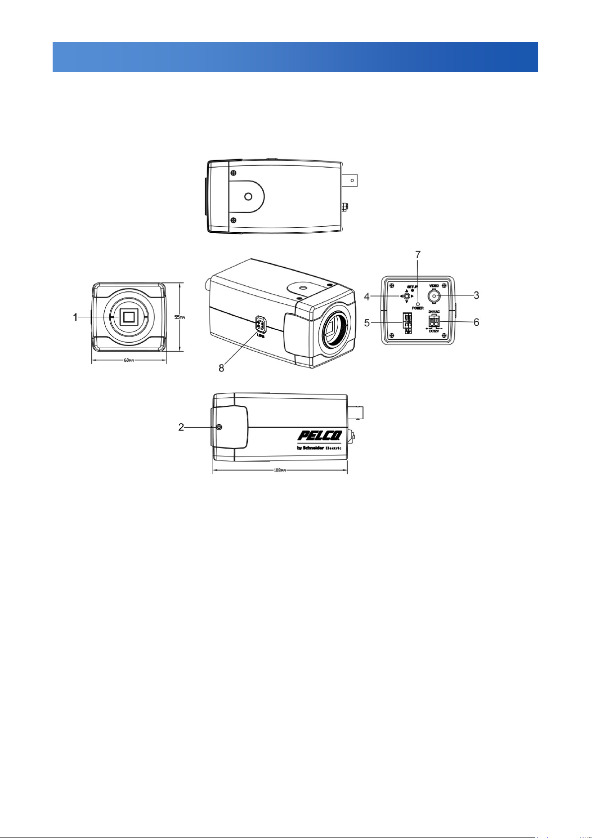
2. Part Names and Locations
Figure 2-1 C20-CH-6/C20-CH-6X
7
C3902M-EN (02/1 2)
Page 8

Part Names and Locations
Figure 2-2 C20-CH-7X
8
C3902M-EN (02/1 2)
Page 9

Part Names and Locations
(1) Lens mount C/CS
For the installation of CS Mount lenses only, use
no adapter.
Before mounting the C mount lens, you can
screw the C adapter onto the lens, and then
screw the lens onto the lens mount.
(2) Back Focus adjustment
Using Minus wrench to loosen this screw before
you use the Focus Adjustment. To maintain the
correct focus afterwards, ensure that it is
tightened.
(3) Video Output Terminal
BNC: Used to give out the video signal.
Connected to the video input terminal of a
monitor, Matrix, etc. (to be terminated with 75
ohm impedance)
(4) OSD joystick control
Press the OSD joystick control straight down:
• For two seconds to enter the Main menu.
• To enter a screen or to select a submenu
option. A selected menu item blinks.
(5) I/O
Connect your external devices to the
corresponding I/O terminal block. The pins of the
I/O terminal block controls the following signals:
TP+/-: UTP (Unshielded Twisted Pair)
(6) Power Connector
Connect to the respective power source.
• For dual-voltage model: Connect to DC12V or
AC 24V power adapter.
• For high-voltage model: Connect to AC 220V
power source.
WARNING:
This apparatus must be GROUNDED.
(7) Power Indicator
The power indicator light is lit (Red), which
means the power is connected.
(8) Auto Iris lens connector
Supplies power and control signals to an
auto-iris lens.
9
C3902M-EN (02/1 2)
Page 10

OSD Setup Menu
Set up menu
Default set
Menu
Lens
AUTO
AUTO/Manual
Shutter/AGC
AUTO
AUTO (High Luminance, Low Luminance)/ Manual (Mode,
Shutter, AGC)
WHITE BAL
ATW
ATW/Push Lock/User1/User2/Anti CR/Manual
Backlight
OFF
OFF/BLC/HLC
Pic Adjust
Option
Mirror, Brightness, Contrast, Sharpness, Hue, Gain
ATR
OFF
OFF/ON (Luminance, Contrast)
Motion Det
OFF
OFF/ON (Detect Sense, Block DISP, Motion Area, Area Sel)
Privacy
OFF
OFF/ON (Area Sel, Color, Transp, Mosaic)
Day/Night
AUTO
AUTO/BW/Color
NR OFF
NR Mode (Off, Y, C)
Y Level
C Level
Camera ID
OFF
OFF/ON
SYNC
INT
INT
Language
English
ENGLISH / SPANISH / RUSSIAN / GERMAN / FRENCH /
JAPANESE or PORTUGUESE
Camera Reset
Exit
Save All
3. OSD Menu
10
C3902M-EN (02/1 2)
Page 11

Menu Settings
4. OSD Menu Settings
Entering OSD Menu
Hold down on the joystick to open the Main menu. Use the UP/DOWN functions of the joystick to move
the cursor to the item you want to modify. A selected menu item will be highlighted.
Press UP: Press to move the cursor up.
Press Down: Press to move the cursor down.
Enter button: Hold down on the joystick to enter the selected item or change the settings of the
selected item.
Press Right: Press it to change the settings of the selected item.
Press Left: Press it to change the settings of the selected item.
NOTE: When an item is selected, it will be highlighted.
After all the settings have been satisfied, move the cursor to the "Save All" item and press the enter
button. Then move the cursor to the "EXIT" item and press the enter button to exit OSD setup menu.
You can also restore the settings to factory default by moving the cursor to the "CAMERA RESET" item
and then pressing the Enter button. Then move the cursor to the "Save All" item and press the Enter
button.
11
C3902M-EN (02/1 2)
Page 12

Menu Settings
LENS AUTO
SHUTTER/AGC AUTO
WHITE BAL ATW
BACKLIGHT OFF
PICT ADJUST
ATR OFF
MOTION DET OFF
NEXT
EXIT SAVE ALL
PRIVACY OFF
DAY/NIGHT AUTO
NR
CAMERA ID OFF
SYNC INT
LANGUAGE ENGLISH
CAMERA RESET
BACK
EXIT SAVE ALL
TYPE DC
MODE OPEN
SPEED 046
RETURN
Use the OSD menu to set up the camera for optimum performance.
4.1 LENS
Select Auto or Manual lens function. The default setting is AUTO (Auto Iris lens). Move the joystick
control LEFT or RIGHT to select Auto or Manual Lens. Enter the AUTO submenu as shown in the figure.
Move the joystick control UP or DOWN to open, close, or set IRIS to auto mode. Move the joystick
control UP or DOWN to adjust the DC Iris Lens convergence speed.
If speed value is less, the IRIS will be become more slower. If speed value is higher, the IRIS will be
become more faster.
4.2 SHUTTER/AGC
Set Shutter speed/AGC (Auto Gain Control) function. The default setting is AUTO. Move the joystick
control LEFT or RIGHT to select AUTO or MANUAL.
SUGGESTED USE:
DC Lens: When using DC lens, it is recommended to set SHUTTER/AGC to AUTO mode. Enter the
AUTO submenu as shown in the figure. Move the joystick control UP or DOWN to adjust HIGH
LUMINANCE MODE to AUTO IRIS.
Manual Lens: When using MANUAL lens, it is recommended to set SHUTTER/AGC to AUTO mode.
Enter the AUTO submenu as shown in the figure. Move the joystick control UP or DOWN to adjust HIGH
LUMINANCE MODE and LOW LUMINANCE setting.
12
C3902M-EN (02/1 2)
Page 13

Menu Settings
SPEED 171
DELAY CNT 152
ATW FRAME x 0.50
ENVIRONMENT INDOOR
HIGH LUMINANCE
MODE AUTO IRIS
BRIGHTNESS 024
LOW LUMINANCE
MODE AGC
BRIGHTNESS x 0.25
RETURN
MODE SHUT+AGC
SHUTTER 1/50
AGC 6.0
RETURN
AUTO IRIS and SHUT+AUTO IRIS difference
• Use DC lens and setting to AUTO IRIS mode for normal condition application environments. The IRIS
level will be controlled by camera brightness.
• Use DC lens and setting to SHUT+AUTO IRIS mode for high light application environments. The
exposure will be controlled by AES or the DC Iris. The iris level will be controlled by camera brightness.
The shutter speed is variable from 1/50 sec to the 1/10Ksec and the AGC is selectable depending on
your environment condition.
Note:Menu settings for Lens and Shutter/AGC
• When the camera first starts up the menu setting for Lens=Auto (Mode=Auto) and the settings for
Shutter/AGC= High Luminance=Auto Iris
• When you change Lens=Manual then the default settings for Shutter/AGC= High Luminance=Shut
• When you change Lens=Auto then the settings for Shutter/AGC=Shut+AutoIris (this is not the default
value of menu setting when first turned on)
4.3 WHITE BAL
WHITE BALANCE controls color on the screen. The default is ATW. The color temperature range is
2500°K~ 9500°K. Move the joystick control LEFT or RIGHT to select ATW (Auto White Balance), PUSH,
PUSH LOCK, USER1, USER2, Anti CR (Anti Color Rolling Suppression) or MANUAL mode. Enter the
ATW submenu as shown in the figure. Move the joystick control UP or DOWN to select the desired
value. ATW (Auto White Balance) select when the scene illumination varies between indoor scenes and
outdoor scene lighting.
NOTE:
When setting different value of ATW FRAME and application environment, the color temperature range
of white balance will be changed. The color temperature range of x0.50 of ATW FRAME will be smaller
than x2.00.
If selected MANUAL mode, you can adjust LEVEL from 17 to 54.
If selected USER1 or USER2 mode, you can adjust B-GAIN and R-GAIN value from 0 to 255.
If selected PUSH mode in the appropriate position, whole area will perform white balance.
If selected PUSH LOCK mode in the appropriate position, WHITE BALANCE will perform once.
If selected Anti CR mode in the appropriate position, whole area will effectively restrain color cast.
13
C3902M-EN (02/1 2)
Page 14

Menu Settings
MIRROR OFF
BRIGHTNESS 000
CONTRAST 128
SHARPNESS 128
HUE 128
GAIN 128
RETURN
LUMINANCE LOW
CONTRAST LOW
RETURN
DETECT SENSE 100
BLOCK DISP OFF
MONITOR AREA OFF
AREA SEL 1/4
TOP 000
BOTTOM 000
LEFT 000
RIGHT 000
RETURN
4.4 BACKLIGHT
Set Backlight compensation function. The default is OFF. Move the joystick control LEFT or RIGHT to
select OFF, BLC or HLC (Highlight Compensation) mode. When you switched BLC, the function
controls the light level to overcome severe backlighting conditions. HLC activated automatically
depending on the shooting condition (detects night and high-luminance)
BLC and HLC Compensation are the functions that achieve the brightness of a selected area to an
optimum image level. Due to the intense light coming from the back of objects in the area expected to
view, the auto iris lens tends to close and areas desired to see become dark and invisible.
4.5 PICTURE ADJUST
Set PICTURE ADJUST function. Enter PICT ADJUST submenu as shown in the figure. Move the
joystick control UP or DOWN to set picture Brightness, Contrast, Sharpness, Hue, or Gain value. In
addition, you can set MIRROR to the ON mode then the picture to be left or right.
4.6 ATR*
Set ATR (Adaptive Tone-curve Reproduction) function. The default is OFF. Move the joystick control
LEFT or RIGHT to select the ON mode then enter to the ATR submenu, you can set LUMINACE and
CONTRAST to optimize by image.
*Also known as Wide Dynamic Range. This function expands the video dynamic range of the camera
and improves visibility of images even in high contrast environments.
4.7 MOTION DET
Set Motion Detection function. MOTION DET allows detecting moving objects on the screen. The default
is OFF. Move the joystick control LEFT or RIGHT to select the ON mode then enter to the MOTION DET
submenu. You can set 4 motion areas to detect moving objectives and adjusts the motion detection
sensitivity. Use the LEFT/RIGHT functions of the joystick control to set the sensitivity from 000 to 127.
14
C3902M-EN (02/1 2)
Page 15

Menu Settings
BURST OFF
DELAY CNT 100
DAY->NIGHT 100
NIGHT->DAY 100
RETURN
NR MODE Y/C
Y LEVEL 000
C LEVEL 000
RETURN
REA SEL 1/8
TOP 000
BOTTOM 000
LEFT 000
RIGHT 000
COLOR 1
TRANSP 0.00
MOSAIC OFF
RETURN
4.8 PRIVACY
Set PRIVACY function. The default setting is OFF. Move the joystick control LEFT or RIGHT to select
the ON mode then enter to the PRIVACY submenu. You can configure 8 privacy positions, set 8 privacy
areas, choose different color zone and set transparency of 8 privacy zone. However if you enable
MOTION DET function, then PRIVACY function will be supported 4 zones only. In addition, the image
of PRIVACY can allow you to set MOSAIC function.
4.9 DAY/NIGHT
Set DAY/NIGHT function. The default setting is AUTO. Move the joystick control LEFT or RIGHT to
select the AUTO, COLOR, BW mode. Enter the AUTO submenu as shown in the figure. Move the
joystick control UP or DOWN to adjust BURST value and set the time before the camera switches to
DAY-> NIGHT mode or NIGHT->DAY mode.
When select Day->NIGHT level to set up switchover point of brightness from COLOR mode to B/W mode
under different Lux levels.
When select NIGHT->DAY level to set up switchover point of brightness from B/W mode to COLOR
mode under different Lux levels.
If selected COLOR mode, you can force the camera to stay in DAY (COLOR) mode.
If selected BW mode, you can force the camera to stay in BW (NIGHT) mode. The BW submenu allows
you to select BURST to be ON or OFF.
4.10 NR
You can configure the 2D DNR (Digital Noise Reduction) settings and reduce noise on the screen. Enter
NR submenu as shown in the figure. Move the joystick control UP or DOWN to set NR MODE. When
you enable the NR MODE to the Y (BRIGHT) / C (COLOR), C LEVEL or Y LEVEL mode, you can adjust
Y LEVEL or C LEVEL depending on your environment condition.
NOTE: When the Y Level is higher the noise in dark areas becomes lessened. Also, resolution will
become lower. When it is lower, there is more noise in dark areas.
15
C3902M-EN (02/1 2)
Page 16

Menu Settings
When the C Level is higher the noise in dark areas becomes lessened. Also, resolution will become
lower. When it is lower, there is more noise in dark areas.
In the dark environment, you can adjust the value higher of Y Level to reduce the dark noise; adjust the
value higher of C Level to reduce the color noise.
4.11 CAMERA ID
CAMERA ID displays ON or OFF. The default setting is OFF. You can set the ON mode to add a camera
title up to 26 characters with 2 lines and also select where the title appears on the monitor screen.
4.12 SYNC
The default setting is INT. This has no adjustment.
4.13 LANGUAGE
OSD supports 6 multi built in languages. The default setting is English. Move the joystick control LEFT or
RIGHT to select the ENGLISH / SPANISH / RUSSIAN / GERMAN / FRENCH / JAPANESE or
PORTUGUESE.
4.14 CAMERA RESET
Move to the CAMERA RESET mode then Press the ENTER key to recall factory settings.
4.15 SAVE ALL
Save all settings and exit.
16
C3902M-EN (02/1 2)
Page 17

Specification
Camera System Type
C20-CH-6
C20-CH-6X
C20-CH-7X
Format
NTSC
PAL
Optical System
Imager Size
1/3"
Electric
Sync System
Internal
Lens Mount
CS
Lens Drive
DC
Horizontal Resolution
650 TV lines
Sensitivity
f/1.2; 2,850°K; 30IRE
Color (17 ms) 0.25 Lux
Mono (17 ms) 0.25 Lux
f/1.2; 2,850°K; 30IRE
Color (20 ms) 0.25 Lux
Mono (20 ms) 0.25 Lux
S/N Ratio
default 48dB
>52dB by parameter adjustment
Shutter
Auto: 1/60~1/10,000 Manual:
1/60~10,000
Auto: 1/50~1/10,000
Manual: 1/50~10,000
AGC
Off/On 35dB
Color Correction
With White Balance
White Balance
ATW/Push Lock/Manual/Anti CR/User2/User/Push
BLC
Off/ BLC/ HLC(High Light compensation) (selectable)
WDR
On / Off (selectable, ATR)
Noise Reduction-DNR
2D
Motion Detection
Yes
Privacy Zones
Yes
CAMERA ID
Yes
Connection/Termination
Terminal Strip - Removable
Set Up/OSD Input Device
Input Buttons/5 Way Rocker
Multi Language
English, Russian, German,
French, Spanish, Japanese
English, Russian, German, French,
Spanish, Portuguese
UTP
Yes
Power supply
Power
12VDC/24VAC, Autosensing +10/-15%
220VAC, +10/-15%
Power Consumption (Max)
3.5W
4W
Environment
Operating Temperature Range
14°F (-10°C) Minimum,
122°F (50°C) Maximum
Operating humidity
20~90% non-condensing
Mechanism
Construction
Diecast
Dimension (L W H)
60mm X55mm X108mm
Weight (unit)
300g
450g
Power LED
Red-Rear Panel
5. Specification
17
C3902M-EN (02/1 2)
Page 18

PRODUCT WARRANTY AND RETURN INFORMATION
WARRANTY
Pelco will repair or replace, without charge, any
merchandise proved defective in material or
workmanship for a period of one year after the
date of shipment.
Exceptions to this warranty are as noted below:
• Five years:
– Fiber optic products
– Unshielded Twisted Pair (UTP) transmission
products
– CC3701H-2, CC3701H-2X, CC3751H-2,
CC3651H-2X, MC3651H-2, and MC3651H2X camera models
• Three years:
– FD Series and BU Series analog camera
models.
– Fixed network cameras and network dome
cameras with Sarix® technology
– Sarix thermal imaging products (TI and ESTI
Series)
– Fixed camera models (C20 Series,
CCC1390H Series, C10DN Series, C10CH
Series)
– EH1500 Series enclosures
– Spectra
®
IV products (including Spectra IV
IP)
– Spectra HD dome products
– Camclosure
®
IS Series integrated camera
systems
– DX Series video recorders (except DX9000
Series which is covered for a period of one
year), DVR5100 Series digital video
recorders, Digital Sentry® Series hardware
products, DVX Series digital video recorders,
and NVR300 Series network video
recorders
– Endura
®
Series distributed network-based
video products
– Genex
®
Series products (multiplexers,
server, and keyboard)
– PMCL200/300/400 Series LCD monitors
– PMCL5xxF Series and PMCL5xxNB Series
LCD monitors
• Two years:
– Standard varifocal, fixed focal, and
motorized zoom lenses
– DF5/DF8 Series fixed dome products
– Legacy
®
Series integrated positioning
systems
– Spectra III
™
, Spectra Mini, Spectra Mini IP,
Esprit®, ExSite®, ExSite IP, and PS20
scanners, including when used in
continuous motion applications
– Esprit Ti and TI2500 Series thermal imaging
products
– Esprit and WW5700 Series window wiper
(excluding wiper blades)
– CM6700/CM6800/CM9700 Series matrix
– Digital Light Processing (DLP
®
) displays
(except lamp and color wheel). The lamp
and color wheel will be covered for a period
of 90 days. The air filter is not covered
under warranty.
• Six months:
– All pan and tilts, scanners, or preset lenses
used in continuous motion applications
(preset scan, tour, and auto scan modes)
Pelco will warrant all replacement parts and
repairs for 90 days from the date of Pelco
shipment. All goods requiring warranty repair
shall be sent freight prepaid to a Pelco
designated location. Repairs made necessary
by reason of misuse, alteration, normal wear, or
accident are not covered under this warranty.
Pelco assumes no risk and shall be subject to
no liability for damages or loss resulting from the
specific use or application made of the Products.
Pelco’s liability for any claim, whether based on
breach of contract, negligence, infringement of
any rights of any party or product liability,
relating to the Products shall not exceed the
price paid by the Dealer to Pelco for such
Products. In no event will Pelco be liable for any
special, incidental, or consequential damages
(including loss of use, loss of profit, and claims
of third parties) however caused, whether by the
negligence of Pelco or otherwise.
The above warranty provides the Dealer with
specific legal rights. The Dealer may also have
additional rights, which are subject to variation
from state to state.
If a warranty repair is required, the Dealer must
contact Pelco at (800) 289-9100 or (559) 2921981 to obtain a Repair Authorization number
(RA), and provide the following information:
1. Model and serial number
2. Date of shipment, P.O. number, sales order
number, or Pelco invoice number
3. Details of the defect or problem
If there is a dispute regarding the warranty of a
product that does not fall under the warranty
conditions stated above, please include a
18
C3902M-EN (02/1 2)
Page 19

PRODUCT WARRANTY AND RETURN INFORMATION
This equipment contains electrical or electronic components that must be recycled
properly to comply with Directive 2002/96/EC of the European Union regarding the
disposal of waste electrical and electronic equipment (WEEE). Contact your local
dealer for procedures for recycling this equipment.
written explanation with the product when
returned.
number if returned for credit, and RA number if
returned for repair) and designated return
location.
Method of return shipment shall be the same or
equal to the method by which the item was
received by Pelco.
All merchandise returned for credit may be
subject to a 20 percent restocking and
refurbishing charge.
RETURNS
To expedite parts returned for repair or credit,
please call Pelco at (800) 289-9100 or (559)
Goods returned for repair or credit should be
clearly identified with the assigned CA or RA
number and freight should be prepaid.
292-1981 to obtain an authorization number (CA
Pelco, the Pelco logo, and other trademarks associated with Pelco products referred to in this publication are trademarks of Pelco, Inc. or its affiliates. © Copyright 2012, Pelco, Inc.
All other product names and services are the property of their respective companies. All rights reserved.
Product specifications and availability are subject to change without notice.
19
C3902M-EN (02/1 2)
Page 20

www.pelco.com
Pelco by Schneider Electric 3500 Pelco Way Clovis, California 93612-5699 United States
USA & Canada Tel (800) 289-9100 Fax (800) 289-9150
International Tel +1 (559) 292-1981 Fax +1 (559) 348-1120
20
 Loading...