

Page 1
®
Installation/Operation
PMCL15A
TFT LCD Monitor
C1965M-C (12/03)
Pelco • 3500 Pelco Way • Clovis, CA 93612-5699 USA • www.pelco.com
In North America and Canada: Tel (800) 289-9100 • FAX (800) 289-9150
International Customers: Tel +1(559) 292-1981 • FAX +1(559) 348-1120
Page 2

CONTENTS
Section Page
IMPORTANT SAFEGUARDS AND WARNINGS ..................................................................................... 3
REGULATORY NOTICES ........................................................................................................................ 3
DESCRIPTION ........................................................................................................................................ 4
INSTALLATION ........................................................................................................................................ 4
Front Panel Controls ..................................................................................................... 7
OPERATION ............................................................................................................................................ 8
How To Adjust The Video .............................................................................................. 8
Video Mode ................................................................................................................... 9
PC Mode ...................................................................................................................... 10
MAINTENANCE ...................................................................................................................................... 11
SPECIFICATIONS .................................................................................................................................. 11
WARRANTY AND RETURN INFORMATION ......................................................................................... 12
List of Illustrations
Figure Page
1 PMCL15A, Rear View ............................................................................................................... 4
2 Looping Operation - One monitor with External Video Equipment ............................................ 5
3 Looping Operation - Maximum of Three Monitors With external Video Equipment .................. 6
4 PMCL15A, Front Panel Controls ............................................................................................... 7
List of Tables
Table Page
AVideo Coaxial Cable Requirements .......................................................................................... 5
[
]
2
Pelco Manual C1965M-C (12/03)
Page 3
IMPORTANT SAFEGUARDS AND WARNINGS
Prior to installation and use of this product, the following WARNINGS should be observed.
1. Installation and servicing should only be done by qualified service personnel and conform to all local
codes.
2. Unless the unit is specifically marked as a NEMA Type 3, 3R, 3S, 4, 4X ,6 or 6P enclosure, it is
designed for indoor use only and it must not be installed where exposed to rain and moisture.
3. Only use replacement parts recommended by Pelco.
4. After replacement/repair of this unit’s electrical components, conduct a resistance measurement
between line and exposed parts to verify the exposed parts have not been connected to line circuitry.
The product and/or manual may bear the following marks:
This symbol indicates that dangerous voltage
constituting a risk of electric shock is present
within this unit.
CAUTION:
RISK OF ELECTRIC SHOCK.
DO NOT OPEN.
This symbol indicates that there are important
operating and maintenance instructions in the
literature accompanying this unit.
Please thoroughly familiarize yourself with the information in this manual prior to installation and operation.
Regulatory Notices
This equipment has been tested and found to comply with the limits of a Class B digital device, pursuant
to part 15 of the FCC rules. These limits are designed to provide reasonable protection against harmful
interference in a residential installation. This equipment generates, uses, and can radiate radio frequency
energy and, if not installed and used in accordance with the instructions, may cause harmful interference
to radio communications. However, there is no guarantee that the interference will not occur in a particular
installation. If this equipment does cause harmful interference to radio or television reception, which can
be determined by turning the equipment off and on, the user is encouraged to try and correct the interference by one or more of the following measures:
• Reorient or relocate the receiving antenna.
• Increase the separation between the equipment and the receiver.
• Connect the equipment into an outlet on a circuit different from that to which the receiver is connected.
• Consult the dealer or an experienced radio/TV technician for help.
Any changes or modifications not expressly approved by the party responsible for compliance could void
the user ’s authority to operate the equipment.
Pelco Manual C1965M-C (12/03)
[
]
3
Page 4
DESCRIPTION
The PMCL15A is a high resolution, 15-inch, thin film transistor (TFT) LCD color monitor. The unit produces
a sharp picture with a resolution of 540 TV lines. The monitor features multiple video inputs for S-video
and PC-based imaging and supports circuitry for NTSC/PAL formats with input voltages of 100-240 VAC.
INSTALLATION
1. The monitor can be placed on any flat surface, desk, or table.
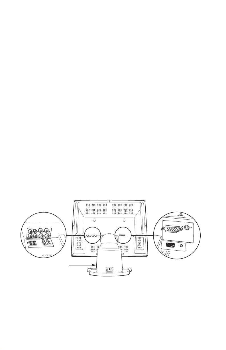
2. Refer to Figure 1 and connect the video signal to the monitor. Refer to Table A for video coaxial cable
requirements.
Available inputs include the following:
BNC Connect the video cable to the BNC input labeled VIDEO IN 1on the back of the
monitor. If the installation requires a second video input, connect a video cable
to the BNC input labeled VIDEO IN 2.
Looping Operation Only - Connect a video cable to the BNC connector labeled
VIDEO OUT 1. If the installation requires a second video output, connect a video
cable to the BNC output labeled VIDEO OUT 2. Refer to Figures 2 and 3.
S-VIDEO Connect the video cable to the input labeled S/VHS IN.
PC-BASED Connect the PC signal cable to the input labeled PC VIDEO IN.
3. Plug the monitor power cord (provided) into the AC INLET connection on the back of the base. Plug
the other end of the cord into a power receptacle.
S
V
C
R
MAIN POWER
SWITCH
[
]
4
Pelco Manual C1965M-C (12/03)
Figure 1. PMCL15A, Rear View
Page 5

Table A. Video Coaxial Cable Requirements
Cable Type* Maximum Distance
RG59/U 750 ft (229 m)
RG6/U 1,000 ft (305 m)
RG11/U 1,500 ft (457 m)
* Minimum cable requirements:
75 ohms impedance
All-copper center conductor
All-copper braided shield with 95% braid coverage
Figure 2. Looping Operation - One Monitor with External Video Equipment
Pelco Manual C1965M-C (12/03)
[
]
5
Page 6

Figure 3. Looping Operation - Maximum of Three Monitors With External Video Equipment
[
]
6
Pelco Manual C1965M-C (12/03)
Page 7

Front Panel Controls
Refer to Figure 4.
1 CHANNEL BUTTON
Channel Select - Press the Channel button once to display a camera view.
Auto Scan - Press and hold the button for three seconds to sequence through composite video channels.
2 MENU BUTTON - On-screen display menu (OSD).
3 BUTTONS - Use to navigate through the OSD menus.
4 POWER LED
Green - Power ON
Dark - Power OFF
Yellow - Power-saving mode
5 POWER BUTTON - Press the power button to turn the monitor ON/OFF.
1
2 3 4 5
Channel
Menu
Figure 4. PMCL15A, Front Panel Controls
00871
Pelco Manual C1965M-C (12/03)
[
]
7
Page 8

OPERATION
1. Turn the monitor’s main power switch ON. The power switch is located on the base of the monitor
(refer to Figure 1).
2. Push IN the power button located on the front of the monitor (refer to Figure 4). The LED turns green.
3. Push the Channel button to select the input signal.
4. If required, adjust the video using the front panel controls and the on-screen display (OSD).
How To Adjust The Video
Use the front control panel to adjust the screen display.
1. Press the Menu button to access the OSD.
2. Press the ▲▼ buttons to move to an icon in the main menu.
3. Press the Menu button to select the icon submenu.
4. Press buttons to adjust the value in the submenu.
5. Press the Menu button to return to the main menu.
6. To exit the main menu press the ▲▼ to move to the EXIT icon, and then press the Menu button.
▲
▲
▲
▲
▲
▲
[
]
8
Pelco Manual C1965M-C (12/03)
Page 9

Video Mode
BRIGHTNESS Press the button to increase brightness and the button to
decrease brightness. Default setting is 80%.
▲
▲
CONTRAST Proper adjustment will allow maximum gradations between the
darkest and lightest picture contrast.
Press the button to increase contrast and the button to
▲
decrease contrast. Default setting is 70%.
RGB
COLOR Press the button to increase saturation level and the button to
▲
decrease color saturation level. Default setting is 62%.
TINT Press the button to increase greenish tones in the picture. Press
the button to increase the reddish tones in the picture. Default
▲
▲
setting is 50%.
SHARPNESS Adjust the controls to obtain the clearest picture. Default setting is 2.
SEQUENCE TIME Set the sequencing time between channels. Press the button to
increase the time. Maximum setting is 24-second interval. Press the
▲
button to decrease the time. Minimum setting is 1-second inter-
val. Default setting is 3-second interval.
OSD H POSITION Adjust the horizontal location of the OSD.
OSD V POSITION Adjust the vertical location of the OSD.
VOLUME Press the button to increase volume and the button to
▲
decrease volume level. Default setting is 50%.
LANGUAGE Select the OSD language—English, French, German, Spanish, or
Italian. Default setting is English.
TITLE ENABLE Turn the camera title on or off (select YES or NO).
▲
▲
▲
▲
TITLE EDITING Edit the camera title. Select a camera, and then press the Menu
button to enter title editing submenu. A title can be sixteen characters long. Press the buttons to select a character location and
▲
▲
press the ▲▼ buttons to change the character. Press the Menu
button to return to the submenu.
RECALL Reset all values to factory preset values.
EXIT
EXIT Select to exit OSD menu.
Pelco Manual C1965M-C (12/03)
[
]
9
Page 10

PC Mode
CONTRAST Proper adjustment will allow maximum gradations between the
darkest and lightest picture contrast. Press the button to
increase contrast and the button to decrease contrast. Default
▲
setting is 85%
BRIGHTNESS Press the button to increase brightness and the button to
▲
decrease brightness. Default setting is 80%.
H POSITION Adjust the horizontal position of the image on the screen.
V POSITION Adjust the vertical position of the image on the screen.
PHASE Adjust the phase.
CLOCK Press the buttons to set the clock.
RGB
COLOR Press the buttons to select a color. Press the ▲▼ buttons to
▲
▲
▲
▲
adjust the value of the selected color.
AUTO ADJUST Automatically adjusts the H position, V position, phase, and clock
values. Default position is ON.
VOLUME Press the buttons for the desired audio level.
▲
▲
OSD H POSITION Adjust the horizontal location of the OSD.
OSD V POSITION Adjust the vertical location of the OSD.
LANGUAGE Select the OSD language—English, French, German, Spanish, or
Italian. Default setting is English.
▲
▲
COLOR TEMP Set the color temperature of the LCD monitor for the CIE coordinate
9300°k or 6500°k.
RECALL MODE DATA Recall the H position, V position, phase, and clock values of the
mode data.
EXIT
EXIT Select to exit OSD menu.
[
]
10
Pelco Manual C1965M-C (12/03)
Page 11

MAINTENANCE
If the quality of the picture is poor and cannot be improved by making adjustments on the front control
panel, inspect all system connections and cable runs.
To reduce the risk of electrical shock, do not remove the cover or back of monitor. No user-serviceable
parts are inside. Refer servicing to qualified personnel or contact the Pelco Technical Support Department for assistance. Refer to the
Warranty and Return Information
section.
SPECIFICATIONS
ELECTRICAL
Input Voltage: 100-240 VAC, 50/60 Hz, automatic switching
Power Consumption
Normal: 35 watts maximum
Standby: 5 watts maximum
Horizontal Resolution: 540 TV lines
Visual Picture Size: 15-inch diagonal
Sweep Linearity: 10%
Speaker Output: 1.0 watt (-3 dBV)
Connectors
Video Input/Output: BNC
S-VHS Input: 4-pin mini DIN
PC Input: 15-pin connector
Audio Input/Output: RCA
AC Power Cord: 2 (1 USA standard and 1 European standard)
GENERAL
Environment: Indoor
Construction: Black plastic
Finish: Black matte texture coat finish
LCD Panel:
Type: 15-inch (38.1 cm) TFT color
Colors: 16.7M colors
Viewable Size: 12 (H) x 9 (V) inches
Contrast Ratio: 300:1
Brightness: 200 cd/m
Resolution: 1024 x 768 pixels
Dimensions
LCD Panel Only: 12.0" H x 15.4" W x 2.78" D
LCD Panel with Base: 15.6" H x 15.4" W x 7.2" D
Unit Weight 11.2 lb (5 kg)
Shipping Weight 16 lb (7.26 kg)
(30.48 x 22.86 cm)
2
(30.48 x 39.05 x 7.11 cm)
(39.5 x 39.1 x 18.3 cm)
ENVIRONMENTAL
Operating
Te mperature 50° to 104°F (10° to 40°C)
Humidity 20% to 85% (non-condensing)
(Design and product specifications subject to change without notice.)
Pelco Manual C1965M-C (12/03)
[
11
]
Page 12

PRODUCT WARRANTY AND RETURN INFORMATION
WARRANTY
Pelco will repair or replace, without charge, any merchandise proved defective in material or workmanship for a period of one year after the date of
shipment.
Exceptions to this warranty are as noted below:
• Five years on FT/FR8000 Series fiber optic products.
• Three years on Genex
• Three years on Camclosure® and fixed camera models, except the CC3701H-2, CC3701H-2X, CC3751H-2, CC3651H-2X, MC3651H-2, and
MC3651H-2X camera models, which have a five-year warranty.
•Two years on standard motorized or fixed focal length lenses.
•Two years on Legacy
•Two years on Spectra®, Esprit®, ExSite™, and PS20 scanners, including when used in continuous motion applications.
•Two years on Esprit® and WW5700 Series window wiper (excluding wiper blades).
• Eighteen months on DX Series digital video recorders, NVR300 Series network video recorders, and Endura™ Series distributed network-based video
products.
• One year (except video heads) on video cassette recorders (VCRs). Video heads will be covered for a period of six months.
• Six months on all pan and tilts, scanners or preset lenses used in continuous motion applications (that is, preset scan, tour and auto scan modes).
Pelco will warrant all replacement parts and repairs for 90 days from the date of Pelco shipment. All goods requiring warranty repair shall be sent freight
prepaid to Pelco, Clovis, California. Repairs made necessary by reason of misuse, alteration, normal wear, or accident are not covered under this
warranty.
Pelco assumes no risk and shall be subject to no liability for damages or loss resulting from the specific use or application made of the Products. Pelco’s
liability for any claim, whether based on breach of contract, negligence, infringement of any rights of any party or product liability, relating to the Products
shall not exceed the price paid by the Dealer to Pelco for such Products. In no event will Pelco be liable for any special, incidental or consequential
damages (including loss of use, loss of profit and claims of third parties) however caused, whether by the negligence of Pelco or otherwise.
The above warranty provides the Dealer with specific legal rights. The Dealer may also have additional rights, which are subject to variation from state
to state.
If a warranty repair is required, the Dealer must contact Pelco at (800) 289-9100 or (559) 292-1981 to obtain a Repair Authorization number (RA), and
provide the following information:
1. Model and serial number
2. Date of shipment, P.O. number, Sales Order number, or Pelco invoice number
3. Details of the defect or problem
If there is a dispute regarding the warranty of a product which does not fall under the warranty conditions stated above, please include a written
explanation with the product when returned.
Method of return shipment shall be the same or equal to the method by which the item was received by Pelco.
RETURNS
In order to expedite parts returned to the factory for repair or credit, please call the factory at (800) 289-9100 or (559) 292-1981 to obtain an authorization
number (CA number if returned for credit, and RA number if returned for repair).
All merchandise returned for credit may be subject to a 20% restocking and refurbishing charge.
Goods returned for repair or credit should be clearly identified with the assigned CA or RA number and freight should be prepaid. Ship to the appropriate
address below.
If you are located within the continental U.S., Alaska, Hawaii or Puerto Rico, send goods to:
Service Department
Pelco
3500 Pelco Way
Clovis, CA 93612-5699
If you are located outside the continental U.S., Alaska, Hawaii or Puerto Rico and are instructed to return goods to the USA, you may do one of the
following:
If the goods are to be sent by a COURIER SERVICE, send the goods to:
Pelco
3500 Pelco Way
Clovis, CA 93612-5699 USA
®
Series products (multiplexers, server, and keyboard).
®
, CM6700/CM6800/CM9700 Series matrix, and DF5/DF8 Series fixed dome products.
If the goods are to be sent by a FREIGHT FORWARDER, send the goods to:
Pelco c/o Expeditors
473 Eccles Avenue
South San Francisco, CA 94080 USA
Phone: 650-737-1700
Fax: 650-737-0933
Pelco, the Pelco logo, Camclosure, Esprit, Genex, Legacy, and Spectra are registered trademarks of Pelco.
Endura and ExSite are trademarks of Pelco. © Copyright 2001, Pelco. All rights reserved.
REVISION HISTORY
Manual # Date Comments
C1965M 6/01 Original version.
C1965M-A 7/01 Modified format and specifications.
C1965M-B 7/01 Revised Front Panel Controls section.
C1965M-C 12/03 Changed specifications and illustrations for BNC connector; updated icons.
[
]
12
Pelco Manual C1965M-C (12/03)
 Loading...