

Page 1
OPERATION
DVR5100 Series Hybrid Video Recorder
C1696M-A (7/08)
Page 2

Contents
Regulatory Notices . . . . . . . . . . . . . . . . . . . . . . . . . . . . . . . . . . . . . . . . . . . . . . . . . . . . . . . . . . . . . . . . . . . . . . . . . . . . . . . . . . . . . . . . . . . . . . . . . . . .6
About the DVR5100 Series Hybrid Video Recorder. . . . . . . . . . . . . . . . . . . . . . . . . . . . . . . . . . . . . . . . . . . . . . . . . . . . . . . . . . . . . . . . . . . . . . . . . . . .7
New Product Features . . . . . . . . . . . . . . . . . . . . . . . . . . . . . . . . . . . . . . . . . . . . . . . . . . . . . . . . . . . . . . . . . . . . . . . . . . . . . . . . . . . . . . . . . . . . .8
Getting Started . . . . . . . . . . . . . . . . . . . . . . . . . . . . . . . . . . . . . . . . . . . . . . . . . . . . . . . . . . . . . . . . . . . . . . . . . . . . . . . . . . . . . . . . . . . . . . . . . . . . . . .9
Logging On . . . . . . . . . . . . . . . . . . . . . . . . . . . . . . . . . . . . . . . . . . . . . . . . . . . . . . . . . . . . . . . . . . . . . . . . . . . . . . . . . . . . . . . . . . . . . . . . . . . . . .9
Shutting Down . . . . . . . . . . . . . . . . . . . . . . . . . . . . . . . . . . . . . . . . . . . . . . . . . . . . . . . . . . . . . . . . . . . . . . . . . . . . . . . . . . . . . . . . . . . . . . . . . .10
Logging Off . . . . . . . . . . . . . . . . . . . . . . . . . . . . . . . . . . . . . . . . . . . . . . . . . . . . . . . . . . . . . . . . . . . . . . . . . . . . . . . . . . . . . . . . . . . . . . . . . . . . .11
Understanding DVR5100 Controls and Menus . . . . . . . . . . . . . . . . . . . . . . . . . . . . . . . . . . . . . . . . . . . . . . . . . . . . . . . . . . . . . . . . . . . . . . . . . . . . . . 12
Application Modes . . . . . . . . . . . . . . . . . . . . . . . . . . . . . . . . . . . . . . . . . . . . . . . . . . . . . . . . . . . . . . . . . . . . . . . . . . . . . . . . . . . . . . . . . . . . . . .13
USB PC Keyboard/Mouse and Control Pad Functions . . . . . . . . . . . . . . . . . . . . . . . . . . . . . . . . . . . . . . . . . . . . . . . . . . . . . . . . . . . . . . . . . . . .14
Displaying and Hiding the System Menus. . . . . . . . . . . . . . . . . . . . . . . . . . . . . . . . . . . . . . . . . . . . . . . . . . . . . . . . . . . . . . . . . . . . . . . . . . . . .17
Navigating to and Selecting a Menu Item. . . . . . . . . . . . . . . . . . . . . . . . . . . . . . . . . . . . . . . . . . . . . . . . . . . . . . . . . . . . . . . . . . . . . . . . . . . . .17
Showing and Hiding Online Help for the Control Pad . . . . . . . . . . . . . . . . . . . . . . . . . . . . . . . . . . . . . . . . . . . . . . . . . . . . . . . . . . . . . . . . . . . .18
Showing System Information. . . . . . . . . . . . . . . . . . . . . . . . . . . . . . . . . . . . . . . . . . . . . . . . . . . . . . . . . . . . . . . . . . . . . . . . . . . . . . . . . . . . . . .19
On-Screen Menus. . . . . . . . . . . . . . . . . . . . . . . . . . . . . . . . . . . . . . . . . . . . . . . . . . . . . . . . . . . . . . . . . . . . . . . . . . . . . . . . . . . . . . . . . . . . . . . . 19
Shortcut Menus . . . . . . . . . . . . . . . . . . . . . . . . . . . . . . . . . . . . . . . . . . . . . . . . . . . . . . . . . . . . . . . . . . . . . . . . . . . . . . . . . . . . . . . . . . . . . . . . .20
Radio and Television Interference. . . . . . . . . . . . . . . . . . . . . . . . . . . . . . . . . . . . . . . . . . . . . . . . . . . . . . . . . . . . . . . . . . . . . . . . . . . . . . . .6
Frame Rate Notice Regarding User-Selected Options . . . . . . . . . . . . . . . . . . . . . . . . . . . . . . . . . . . . . . . . . . . . . . . . . . . . . . . . . . . . . . . .6
Autologin . . . . . . . . . . . . . . . . . . . . . . . . . . . . . . . . . . . . . . . . . . . . . . . . . . . . . . . . . . . . . . . . . . . . . . . . . . . . . . . . . . . . . . . . . . . . . . . . . . .9
Logging On with the Keyboard and Mouse. . . . . . . . . . . . . . . . . . . . . . . . . . . . . . . . . . . . . . . . . . . . . . . . . . . . . . . . . . . . . . . . . . . . . . . . .9
Logging On with the Control Pad. . . . . . . . . . . . . . . . . . . . . . . . . . . . . . . . . . . . . . . . . . . . . . . . . . . . . . . . . . . . . . . . . . . . . . . . . . . . . . . .10
USB Keyboard/Mouse. . . . . . . . . . . . . . . . . . . . . . . . . . . . . . . . . . . . . . . . . . . . . . . . . . . . . . . . . . . . . . . . . . . . . . . . . . . . . . . . . . . . . . . .17
Control Pad. . . . . . . . . . . . . . . . . . . . . . . . . . . . . . . . . . . . . . . . . . . . . . . . . . . . . . . . . . . . . . . . . . . . . . . . . . . . . . . . . . . . . . . . . . . . . . . . .17
Submenus . . . . . . . . . . . . . . . . . . . . . . . . . . . . . . . . . . . . . . . . . . . . . . . . . . . . . . . . . . . . . . . . . . . . . . . . . . . . . . . . . . . . . . . . . . . . . . . . .20
Operating the DVR5100. . . . . . . . . . . . . . . . . . . . . . . . . . . . . . . . . . . . . . . . . . . . . . . . . . . . . . . . . . . . . . . . . . . . . . . . . . . . . . . . . . . . . . . . . . . . . . . .21
Monitoring Live Video. . . . . . . . . . . . . . . . . . . . . . . . . . . . . . . . . . . . . . . . . . . . . . . . . . . . . . . . . . . . . . . . . . . . . . . . . . . . . . . . . . . . . . . . . . . . .21
Selecting a Video Pane . . . . . . . . . . . . . . . . . . . . . . . . . . . . . . . . . . . . . . . . . . . . . . . . . . . . . . . . . . . . . . . . . . . . . . . . . . . . . . . . . . . . . . .21
Changing Screen Layout . . . . . . . . . . . . . . . . . . . . . . . . . . . . . . . . . . . . . . . . . . . . . . . . . . . . . . . . . . . . . . . . . . . . . . . . . . . . . . . . . . . . . .21
Viewing a Specific Camera. . . . . . . . . . . . . . . . . . . . . . . . . . . . . . . . . . . . . . . . . . . . . . . . . . . . . . . . . . . . . . . . . . . . . . . . . . . . . . . . . . . . . . . . .21
Moving Through the Camera Sequence . . . . . . . . . . . . . . . . . . . . . . . . . . . . . . . . . . . . . . . . . . . . . . . . . . . . . . . . . . . . . . . . . . . . . . . . . .22
Calling Up Cameras by Number. . . . . . . . . . . . . . . . . . . . . . . . . . . . . . . . . . . . . . . . . . . . . . . . . . . . . . . . . . . . . . . . . . . . . . . . . . . . . . . . .22
Calling Up Cameras Through the Cameras Menu. . . . . . . . . . . . . . . . . . . . . . . . . . . . . . . . . . . . . . . . . . . . . . . . . . . . . . . . . . . . . . . . . . .22
Disconnecting Cameras. . . . . . . . . . . . . . . . . . . . . . . . . . . . . . . . . . . . . . . . . . . . . . . . . . . . . . . . . . . . . . . . . . . . . . . . . . . . . . . . . . . . . . .23
PTZ Operations. . . . . . . . . . . . . . . . . . . . . . . . . . . . . . . . . . . . . . . . . . . . . . . . . . . . . . . . . . . . . . . . . . . . . . . . . . . . . . . . . . . . . . . . . . . . . . . . . . . . . . . 24
Repositioning a Camera with PTZ Capabilities . . . . . . . . . . . . . . . . . . . . . . . . . . . . . . . . . . . . . . . . . . . . . . . . . . . . . . . . . . . . . . . . . . . . . . . . .24
Using Shortcut Controls for PTZ Operations. . . . . . . . . . . . . . . . . . . . . . . . . . . . . . . . . . . . . . . . . . . . . . . . . . . . . . . . . . . . . . . . . . . . . . . . . . . .25
Pan to Zero. . . . . . . . . . . . . . . . . . . . . . . . . . . . . . . . . . . . . . . . . . . . . . . . . . . . . . . . . . . . . . . . . . . . . . . . . . . . . . . . . . . . . . . . . . . . . . . . .25
Rotate the Camera. . . . . . . . . . . . . . . . . . . . . . . . . . . . . . . . . . . . . . . . . . . . . . . . . . . . . . . . . . . . . . . . . . . . . . . . . . . . . . . . . . . . . . . . . . .25
Using Patterns, Presets, and Scans . . . . . . . . . . . . . . . . . . . . . . . . . . . . . . . . . . . . . . . . . . . . . . . . . . . . . . . . . . . . . . . . . . . . . . . . . . . . . . . . . . 25
Patterns . . . . . . . . . . . . . . . . . . . . . . . . . . . . . . . . . . . . . . . . . . . . . . . . . . . . . . . . . . . . . . . . . . . . . . . . . . . . . . . . . . . . . . . . . . . . . . . . . . .25
Presets. . . . . . . . . . . . . . . . . . . . . . . . . . . . . . . . . . . . . . . . . . . . . . . . . . . . . . . . . . . . . . . . . . . . . . . . . . . . . . . . . . . . . . . . . . . . . . . . . . . .27
Scans . . . . . . . . . . . . . . . . . . . . . . . . . . . . . . . . . . . . . . . . . . . . . . . . . . . . . . . . . . . . . . . . . . . . . . . . . . . . . . . . . . . . . . . . . . . . . . . . . . . . .28
Searching for Recorded Video. . . . . . . . . . . . . . . . . . . . . . . . . . . . . . . . . . . . . . . . . . . . . . . . . .
Quick Search. . . . . . . . . . . . . . . . . . . . . . . . . . . . . . . . . . . . . . . . . . . . . . . . . . . . . . . . . . . . . . . . . . . . . . . . . . . . . . . . . . . . . . . . . . . . . . . . . . . .29
Performing a Quick Search . . . . . . . . . . . . . . . . . . . . . . . . . . . . . . . . . . . . . . . . . . . . . . . . . . . . . . . . . . . . . . . . . . . . . . . . . . . . . . . . . . . .29
Commands and Features. . . . . . . . . . . . . . . . . . . . . . . . . . . . . . . . . . . . . . . . . . . . . . . . . . . . . . . . . . . . . . . . . . . . . . . . . . . . . . . . . . . . . .30
Primary Functions. . . . . . . . . . . . . . . . . . . . . . . . . . . . . . . . . . . . . . . . . . . . . . . . . . . . . . . . . . . . . . . . . . . . . . . . . . . . . . . . . . . . . . . . . . . .30
Secondary Functions . . . . . . . . . . . . . . . . . . . . . . . . . . . . . . . . . . . . . . . . . . . . . . . . . . . . . . . . . . . . . . . . . . . . . . . . . . . . . . . . . . . . . . . . .30
Enhanced Search . . . . . . . . . . . . . . . . . . . . . . . . . . . . . . . . . . . . . . . . . . . . . . . . . . . . . . . . . . . . . . . . . . . . . . . . . . . . . . . . . . . . . . . . . . . . . . . .31
Performing an Enhanced Search . . . . . . . . . . . . . . . . . . . . . . . . . . . . . . . . . . . . . . . . . . . . . . . . . . . . . . . . . . . . . . . . . . . . . . . . . . . . . . . .31
Playing a Video Clip . . . . . . . . . . . . . . . . . . . . . . . . . . . . . . . . . . . . . . . . . . . . . . . . . . . . . . . . . . . . . . . . . . . . . . . . . . . . . . . . . . . . . . . . . . . . . .33
Changing the Playback Speed for Recorded Video . . . . . . . . . . . . . . . . . . . . . . . . . . . . . . . . . . . . . . . . . . . . . . . . . . . . . . . . . . . . . . . . . . . . . .34
Locking and Unlocking a Video Clip . . . . . . . . . . . . . . . . . . . . . . . . . . . . . . . . . . . . . . . . . . . . . . . . . . . . . . . . . . . . . . . . . . . . . . . . . . . . . . . . . .34
Marking an Event . . . . . . . . . . . . . . . . . . . . . . . . . . . . . . . . . . . . . . . . . . . . . . . . . . . . . . . . . . . . . . . . . . . . . . . . . . . . . . . . . . . . . . . . . . . . . . . .35
. . . . . . . . . . . . . . . . . . . . . . . . . . . . . . . . . . . . . . . . .29
2 C1696M-A (7/08)
Page 3

Exporting Video . . . . . . . . . . . . . . . . . . . . . . . . . . . . . . . . . . . . . . . . . . . . . . . . . . . . . . . . . . . . . . . . . . . . . . . . . . . . . . . . . . . . . . . . . . . . . . . . . . . . . .37
Starting an Export. . . . . . . . . . . . . . . . . . . . . . . . . . . . . . . . . . . . . . . . . . . . . . . . . . . . . . . . . . . . . . . . . . . . . . . . . . . . . . . . . . . . . . . . . . . . . . . .37
Canceling an Export in Progress. . . . . . . . . . . . . . . . . . . . . . . . . . . . . . . . . . . . . . . . . . . . . . . . . . . . . . . . . . . . . . . . . . . . . . . . . . . . . . . . . . . . .38
Capturing a Snapshot (Still Image). . . . . . . . . . . . . . . . . . . . . . . . . . . . . . . . . . . . . . . . . . . . . . . . . . . . . . . . . . . . . . . . . . . . . . . . . . . . . . . . . . .39
Working With Alarms . . . . . . . . . . . . . . . . . . . . . . . . . . . . . . . . . . . . . . . . . . . . . . . . . . . . . . . . . . . . . . . . . . . . . . . . . . . . . . . . . . . . . . . . . . . . . . . . .40
Acknowledging an Alarm Event . . . . . . . . . . . . . . . . . . . . . . . . . . . . . . . . . . . . . . . . . . . . . . . . . . . . . . . . . . . . . . . . . . . . . . . . . . . . . . . . . . . . .40
Snoozing an Alarm Event . . . . . . . . . . . . . . . . . . . . . . . . . . . . . . . . . . . . . . . . . . . . . . . . . . . . . . . . . . . . . . . . . . . . . . . . . . . . . . . . . . . . . . . . . .40
Viewing Details. . . . . . . . . . . . . . . . . . . . . . . . . . . . . . . . . . . . . . . . . . . . . . . . . . . . . . . . . . . . . . . . . . . . . . . . . . . . . . . . . . . . . . . . . . . . . . . . . .41
Working with Cameras . . . . . . . . . . . . . . . . . . . . . . . . . . . . . . . . . . . . . . . . . . . . . . . . . . . . . . . . . . . . . . . . . . . . . . . . . . . . . . . . . . . . . . . . . . . . . . . .42
Accessing Camera Menus. . . . . . . . . . . . . . . . . . . . . . . . . . . . . . . . . . . . . . . . . . . . . . . . . . . . . . . . . . . . . . . . . . . . . . . . . . . . . . . . . . . . .42
Adjusting the Audio volume . . . . . . . . . . . . . . . . . . . . . . . . . . . . . . . . . . . . . . . . . . . . . . . . . . . . . . . . . . . . . . . . . . . . . . . . . . . . . . . . . . .43
Adjusting the Iris . . . . . . . . . . . . . . . . . . . . . . . . . . . . . . . . . . . . . . . . . . . . . . . . . . . . . . . . . . . . . . . . . . . . . . . . . . . . . . . . . . . . . . . . . . . .43
Adjusting the Focus. . . . . . . . . . . . . . . . . . . . . . . . . . . . . . . . . . . . . . . . . . . . . . . . . . . . . . . . . . . . . . . . . . . . . . . . . . . . . . . . . . . . . . . . . .44
Working with Scripts and Relays . . . . . . . . . . . . . . . . . . . . . . . . . . . . . . . . . . . . . . . . . . . . . . . . . . . . . . . . . . . . . . . . . . . . . . . . . . . . . . . . . . . . . . . .45
Executing Scripts. . . . . . . . . . . . . . . . . . . . . . . . . . . . . . . . . . . . . . . . . . . . . . . . . . . . . . . . . . . . . . . . . . . . . . . . . . . . . . . . . . . . . . . . . . . . 45
Executing Relays . . . . . . . . . . . . . . . . . . . . . . . . . . . . . . . . . . . . . . . . . . . . . . . . . . . . . . . . . . . . . . . . . . . . . . . . . . . . . . . . . . . . . . . . . . . .46
Activating Auxiliary Commands (Wiper). . . . . . . . . . . . . . . . . . . . . . . . . . . . . . . . . . . . . . . . . . . . . . . . . . . . . . . . . . . . . . . . . . . . . . . . . . . . . . .47
Appendix A: Front Panel Indicators. . . . . . . . . . . . . . . . . . . . . . . . . . . . . . . . . . . . . . . . . . . . . . . . . . . . . . . . . . . . . . . . . . . . . . . . . . . . . . . . . . . . . . .48
C1696M-A (7/08) 3
Page 4

List of Illustrations
1 DVR5100 Network Diagram . . . . . . . . . . . . . . . . . . . . . . . . . . . . . . . . . . . . . . . . . . . . . . . . . . . . . . . . . . . . . . . . . . . . . . . . . . . . . . . . . . . . . . . . .7
2 Autologin Dialog Box . . . . . . . . . . . . . . . . . . . . . . . . . . . . . . . . . . . . . . . . . . . . . . . . . . . . . . . . . . . . . . . . . . . . . . . . . . . . . . . . . . . . . . . . . . . . . .9
3 USB PC Keyboard Template . . . . . . . . . . . . . . . . . . . . . . . . . . . . . . . . . . . . . . . . . . . . . . . . . . . . . . . . . . . . . . . . . . . . . . . . . . . . . . . . . . . . . . . .12
4 DVR5100 Front Panel Control Pad . . . . . . . . . . . . . . . . . . . . . . . . . . . . . . . . . . . . . . . . . . . . . . . . . . . . . . . . . . . . . . . . . . . . . . . . . . . . . . . .12
5 Video Pane Modes . . . . . . . . . . . . . . . . . . . . . . . . . . . . . . . . . . . . . . . . . . . . . . . . . . . . . . . . . . . . . . . . . . . . . . . . . . . . . . . . . . . . . . . . . . . . . . .13
6 DVR5100 Main Menu. . . . . . . . . . . . . . . . . . . . . . . . . . . . . . . . . . . . . . . . . . . . . . . . . . . . . . . . . . . . . . . . . . . . . . . . . . . . . . . . . . . . . . . . . . . . . 17
7 Control Pad Color-Coded Function Keys. . . . . . . . . . . . . . . . . . . . . . . . . . . . . . . . . . . . . . . . . . . . . . . . . . . . . . . . . . . . . . . . . . . . . . . . . . . . . . . 17
8 Sample Icon Path . . . . . . . . . . . . . . . . . . . . . . . . . . . . . . . . . . . . . . . . . . . . . . . . . . . . . . . . . . . . . . . . . . . . . . . . . . . . . . . . . . . . . . . . . . . . . . . .18
9 Help Menu . . . . . . . . . . . . . . . . . . . . . . . . . . . . . . . . . . . . . . . . . . . . . . . . . . . . . . . . . . . . . . . . . . . . . . . . . . . . . . . . . . . . . . . . . . . . . . . . . . . . .18
10 Control Pad Online Help Dialog Box . . . . . . . . . . . . . . . . . . . . . . . . . . . . . . . . . . . . . . . . . . . . . . . . . . . . . . . . . . . . . . . . . . . . . . . . . . . . . . . . .18
11 System Information. . . . . . . . . . . . . . . . . . . . . . . . . . . . . . . . . . . . . . . . . . . . . . . . . . . . . . . . . . . . . . . . . . . . . . . . . . . . . . . . . . . . . . . . . . . . . . .19
12 DVR5100 Menu Hierarchy . . . . . . . . . . . . . . . . . . . . . . . . . . . . . . . . . . . . . . . . . . . . . . . . . . . . . . . . . . . . . . . . . . . . . . . . . . . . . . . . . . . . . . . . . 19
13 Shortcut Menu and Submenus. . . . . . . . . . . . . . . . . . . . . . . . . . . . . . . . . . . . . . . . . . . . . . . . . . . . . . . . . . . . . . . . . . . . . . . . . . . . . . . . . . . . . .20
14 Displaying Video in a 2 x 2 Configuration . . . . . . . . . . . . . . . . . . . . . . . . . . . . . . . . . . . . . . . . . . . . . . . . . . . . . . . . . . . . . . . . . . . . . . . . . . . . .21
15 Displaying a Camera in a Video Pane. . . . . . . . . . . . . . . . . . . . . . . . . . . . . . . . . . . . . . . . . . . . . . . . . . . . . . . . . . . . . . . . . . . . . . . . . . . . . . . . .22
16 Cameras Menu . . . . . . . . . . . . . . . . . . . . . . . . . . . . . . . . . . . . . . . . . . . . . . . . . . . . . . . . . . . . . . . . . . . . . . . . . . . . . . . . . . . . . . . . . . . . . . . . . .22
17 Camera List. . . . . . . . . . . . . . . . . . . . . . . . . . . . . . . . . . . . . . . . . . . . . . . . . . . . . . . . . . . . . . . . . . . . . . . . . . . . . . . . . . . . . . . . . . . . . . . . . . . . .23
18 PTZ Mode Indicated by Blue Border. . . . . . . . . . . . . . . . . . . . . . . . . . . . . . . . . . . . . . . . . . . . . . . . . . . . . . . . . . . . . . . . . . . . . . . . . . . . . . . . . .24
19 Pan to Zero . . . . . . . . . . . . . . . . . . . . . . . . . . . . . . . . . . . . . . . . . . . . . . . . . . . . . . . . . . . . . . . . . . . . . . . . . . . . . . . . . . . . . . . . . . . . . . . . . . . . .25
20 Selecting a Pattern. . . . . . . . . . . . . . . . . . . . . . . . . . . . . . . . . . . . . . . . . . . . . . . . . . . . . . . . . . . . . . . . . . . . . . . . . . . . . . . . . . . . . . . . . . . . . . .26
21 PTZ Operations Dialog Box. . . . . . . . . . . . . . . . . . . . . . . . . . . . . . . . . . . . . . . . . . . . . . . . . . . . . . . . . . . . . . . . . . . . . . . . . . . . . . . . . . . . . . . . .26
22 Stopping a Pattern . . . . . . . . . . . . . . . . . . . . . . . . . . . . . . . . . . . . . . . . . . . . . . . . . . . . . . . . . . . . . . . . . . . . . . . . . . . . . . . . . . . . . . . . . . . . . . . 27
23 Modifying a Preset . . . . . . . . . . . . . . . . . . . . . . . . . . . . . . . . . . . . . . . . . . . . . . . . . . . . . . . . . . . . . . . . . . . . . . . . . . . . . . . . . . . . . . . . . . . . . . .27
24 Scan Shortcut Menu. . . . . . . . . . . . . . . . . . . . . . . . . . . . . . . . . . . . . . . . . . . . . . . . . . . . . . . . . . . . . . . . . . . . . . . . . . . . . . . . . . . . . . . . . . . . . .28
25 Quick Search Dialog Box. . . . . . . . . . . . . . . . . . . . . . . . . . . . . . . . . . . . . . . . . . . . . . . . . . . . . . . . . . . . . . . . . . . . . . . . . . . . . . . . . . . . . . . . . . .29
26 Search/Export Menu . . . . . . . . . . . . . . . . . . . . . . . . . . . . . . . . . . . . . . . . . . . . . . . . . . . . . . . . . . . . . . . . . . . . . . . . . . . . . . . . . . . . . . . . . . . . .31
27 Enhanced Search Dialog Box . . . . . . . . . . . . . . . . . . . . . . . . . . . . . . . . . . . . . . . . . . . . . . . . . . . . . . . . . . . . . . . . . . . . . . . . . . . . . . . . . . . . . . .31
28 Select Cameras Dialog Box . . . . . . . . . . . . . . . . . . . . . . . . . . . . . . . . . . . . . . . . . . . . . . . . . . . . . . . . . . . . . . . . . . . . . . . . . . . . . . . . . . . . . . . .32
29 Search Dialog Box. . . . . . . . . . . . . . . . . . . . . . . . . . . . . . . . . . . . . . . . . . . . . . . . . . . . . . . . . . . . . . . . . . . . . . . . . . . . . . . . . . . . . . . . . . . . . . . .32
30 Playing Recorded Video from the Quick Search Dialog Box . . . . . . . . . . . . . . . . . . . . . . . . . . . . . . . . . . . . . . . . . . . . . . . . . . . . . . . . . . . . . . .33
31 Changing Playback Speed. . . . . . . . . . . . . . . . . . . . . . . . . . . . . . . . . . . . . . . . . . . . . . . . . . . . . . . . . . . . . . . . . . . . . . . . . . . . . . . . . . . . . . . . . .34
32 Marking an Event . . . . . . . . . . . . . . . . . . . . . . . . . . . . . . . . . . . . . . . . . . . . . . . . . . . . . . . . . . . . . . . . . . . . . . . . . . . . . . . . . . . . . . . . . . . . . . . .35
33 Record Dialog Box. . . . . . . . . . . . . . . . . . . . . . . . . . . . . . . . . . . . . . . . . . . . . . . . . . . . . . . . . . . . . . . . . . . . . . . . . . . . . . . . . . . . . . . . . . . . . . . .36
34 Stop Recording . . . . . . . . . . . . . . . . . . . . . . . . . . . . . . . . . . . . . . . . . . . . . . . . . . . . . . . . . . . . . . . . . . . . . . . . . . . . . . . . . . . . . . . . . . . . . . . . . .36
35 Quick Export Menu . . . . . . . . . . . . . . . . . . . . . . . . . . . . . . . . . . . . . . . . . . . . . . . . . . . . . . . . . . . . . . . . . . . . . . . . . . . . . . . . . . . . . . . . . . . . . . .37
36 Export Clip Dialog Box . . . . . . . . . . . . . . . . . . . . . . . . . . . . . . . . . . . . . . . . . . . . . . . . . . . . . . . . . . . . . . . . . . . . . . . . . . . . . . . . . . . . . . . . . . . .37
37 Request for Storage Device . . . . . . . . . . . . . . . . . . . . . . . . . . . . . . . . . . . . . . . . . . . . . . . . . . . . . . . . . . . . . . . . . . . . . . . . . . . . . . . . . . . . . . . . 38
38 Stop Export Dialog Box. . . . . . . . . . . . . . . . . . . . . . . . . . . . . . . . . . . . . . . . . . . . . . . . . . . . . . . . . . . . . . . . . . . . . . . . . . . . . . . . . . . . . . . . . . . . 38
39 Selecting Snapshot from the Quick Export Menu . . . . . . . . . . . . . . . . . . . . . . . . . . . . . . . . . . . . . . . . . . . . . . . . . . . . . . . . . . . . . . . . . . . . . . .39
40 Acknowledging an Alarm . . . . . . . . . . . . . . . . . . . . . . . . . . . . . . . . . . . . . . . . . . . . . . . . . . . . . . . . . . . . . . . . . . . . . . . . . . . . . . . . . . . . . . . . . .40
41 Snoozing an Alarm . . . . . . . . . . . . . . . . . . . . . . . . . . . . . . . . . . . . . . . . . . . . . . . . . . . . . . . . . . . . . . . . . . . . . . . . . . . . . . . . . . . . . . . . . . . . . . .40
42 Alarm Information . . . . . . . . . . . . . . . . . . . . . . . . . . . . . . . . . . . . . . . . . . . . . . . . . . . . . . . . . . . . . . . . . . . . . . . . . . . . . . . . . . . . . . . . . . . . . . .41
43 Camera Settings Menu Example . . . . . . . . . . . . . . . . . . . . . . . . . . . . . . . . . . . . . . . . . . . . . . . . . . . . . . . . . . . . . . . . . . . . . . . . . . . . . . . . . . . .42
44 Iris Dialog Box . . . . . . . . . . . . . . . . . . . . . . . . . . . . . . . . . . . . . . . . . . . . . . . . . . . . . . . . . . . . . . . . . . . . . . . . . . . . . . . . . . . . . . . . . . . . . . . . . .43
45 Open Iris Control. . . . . . . . . . . . . . . . . . . . . . . . . . . . . . . . . . . . . . . . . . . . . . . . . . . . . . . . . . . . . . . . . . . . . . . . . . . . . . . . . . . . . . . . . . . . . . . . .43
46 Close Iris Control. . . . . . . . . . . . . . . . . . . . . . . . . . . . . . . . . . . . . . . . . . . . . . . . . . . . . . . . . . . . . . . . . . . . . . . . . . . . . . . . . . . . . . . . . . . . . . . . .44
47 Focus Dialog Box. . . . . . . . . . . . . . . . . . . . . . . . . . . . . . . . . . . . . . . . . . . . . . . . . . . . . . . . . . . . . . . . . . . . . . . . . . . . . . . . . . . . . . . . . . . . . . . . .44
48 Focus Closer to an Object. . . . . . . . . . . . . . . . . . . . . . . . . . . . . . . . . . . . . . . . . . . . . . . . . . . . . . . . . . . . . . . . . . . . . . . . . . . . . . . . . . . . . . . . . . 44
49 Focus Farther Away from an Object. . . . . . . . . . . . . . . . . . . . . . . . . . . . . . . . . . . . . . . . . . . . . . . . . . . . . . . . . . . . . . . . . . . . . . . . . . . . . . . . . .44
50 Execute Script Dialog Box. . . . . . . . . . . . . . . . . . . . . . . . . . . . . . . . . . . . . . . . . . . . . . . . . . . . . . . . . . . . . . . . . . . . . . . . . . . . . . . . . . . . . . . . . .45
51 No Scripts Found Dialog Box . . . . . . . . . . . . . . . . . . . . . . . . . . . . . . . . . . . . . . . . . . . . . . . . . . . . . . . . . . . . . . . . . . . . . . . . . . . . . . . . . . . . . . .45
52 Activate Relay Dialog Box . . . . . . . . . . . . . . . . . . . . . . . . . . . . . . . . . . . . . . . . . . . . . . . . . . . . . . . . . . . . . . . . . . . . . . . . . . . . . . . . . . . . . . . . .46
53 No Relays Dialog Box . . . . . . . . . . . . . . . . . . . . . . . . . . . . . . . . . . . . . . . . . . . . . . . . . . . . . . . . . . . . . . . . . . . . . . . . . . . . . . . . . . . . . . . . . . . . .46
54 Wiper Submenu . . . . . . . . . . . . . . . . . . . . . . . . . . . . . . . . . . . . . . . . . . . . . . . . . . . . . . . . . . . . . . . . . . . . . . . . . . . . . . . . . . . . . . . . . . . . . . . . . 47
55 DVR5100 Front Panel Indicators. . . . . . . . . . . . . . . . . . . . . . . . . . . . . . . . . . . . . . . . . . . . . . . . . . . . . . . . . . . . . . . . . . . . . . . . . . . . . . . . . . . . .48
4 C1696M-A (7/08)
Page 5

List of Tables
A New and Enhanced DVR5100 Features . . . . . . . . . . . . . . . . . . . . . . . . . . . . . . . . . . . . . . . . . . . . . . . . . . . . . . . . . . . . . . . . . . . . . . . . . . . . . . . .8
B Default User IDs and Passwords . . . . . . . . . . . . . . . . . . . . . . . . . . . . . . . . . . . . . . . . . . . . . . . . . . . . . . . . . . . . . . . . . . . . . . . . . . . . . . . . . . . . .9
C Special Login Controls . . . . . . . . . . . . . . . . . . . . . . . . . . . . . . . . . . . . . . . . . . . . . . . . . . . . . . . . . . . . . . . . . . . . . . . . . . . . . . . . . . . . . . . . . . . . 10
D Live and Playback Controls. . . . . . . . . . . . . . . . . . . . . . . . . . . . . . . . . . . . . . . . . . . . . . . . . . . . . . . . . . . . . . . . . . . . . . . . . . . . . . . . . . . . . . . . .14
E PTZ Controls . . . . . . . . . . . . . . . . . . . . . . . . . . . . . . . . . . . . . . . . . . . . . . . . . . . . . . . . . . . . . . . . . . . . . . . . . . . . . . . . . . . . . . . . . . . . . . . . . . . .15
F Menu Controls . . . . . . . . . . . . . . . . . . . . . . . . . . . . . . . . . . . . . . . . . . . . . . . . . . . . . . . . . . . . . . . . . . . . . . . . . . . . . . . . . . . . . . . . . . . . . . . . . .15
G Quick Search and Export Controls . . . . . . . . . . . . . . . . . . . . . . . . . . . . . . . . . . . . . . . . . . . . . . . . . . . . . . . . . . . . . . . . . . . . . . . . . . . . . . . . . . .16
H DVR5100 Front Panel Features. . . . . . . . . . . . . . . . . . . . . . . . . . . . . . . . . . . . . . . . . . . . . . . . . . . . . . . . . . . . . . . . . . . . . . . . . . . . . . . . . . . . . .48
C1696M-A (7/08) 5
Page 6

Regulatory Notices
This device complies with Part 15 of the FCC Rules. Operation is subject to the following two conditions: (1) this device may not cause harmful
interference, and (2) this device must accept any interference received, including interference that may cause undesired operation.
RADIO AND TELEVISION INTERFERENCE
This equipment has been tested and found to comply with the limits of a Class B digital device, pursuant to Part 15 of the FCC Rules. These limits
are designed to provide reasonable protection against harmful interference in a residential installation. This equipment generates, uses, and can
radiate radio frequency energy and, if not installed and used in accordance with the instructions, may cause harmful interference to radio
communications. However there is no guarantee that the interference will not occur in a particular installation. If this equipment does cause
harmful interference to radio or television reception, which can be det ermined by turnin g the equip ment off and on, the user is encouraged to try
to correct the interference by one or more of the following measures:
• Reorient or relocate the receiving antenna.
• Increase the separation between the e quipment and the receiver.
• Connect the equipment into an outlet on a circuit different from that to which the receiver is connected.
• Consult the dealer or an experienced radio/TV technician for help.
You may also find helpful the following booklet, prepared by the FCC: “How to Identify and Resolve Radio-TV Interference Problems.” This
booklet is available from the U.S. Government Printing Office, Washington D.C. 20402.
Changes and modifications not expressly approved by the manufacturer or registrant of this equipment can void your authority to operate this
equipment under Federal Communications Commission’s rules.
To maintain compliance with FCC regulations, shielded cables must be used with this equipment. Operation with non-approved equipment or
unshielded cables is likely to result in interference to radio and television reception.
This Class B digital apparatus complies with Canadian ICES-003. Cet appareil numérique de la classe B est conforme à la norme NMB-003 du
Canada.
Video Quality Caution
FRAME RATE NOTICE REGARDING USER-SELECTED OPTIONS
Pelco systems are capable of providing high quality video for both live viewing and playback. However, the systems can be used in lower quality
modes, which can degrade picture quality, to allow for a slower rate of data transfer and to reduce the amount of video data stored. The picture
quality can be degraded by either lowering the resolution, reducing the frame rate, or both. A picture degraded by having a reduced resolution
may result in an image that is less clear or even indiscernible. A picture degraded by reducing the picture rate has fewer frames per second,
which can result in images that appear to jump or move more quickly than normal during playback. Lower frame rates may result in a key event
not being recorded by the system.
Judgment as to the suitability of the products for users’ purposes is solely the users’ responsibility. Users should refer to the operation manuals
for cautionary statements regarding user selected options and how they might affect video quality. Users shall determine the suitability of the
products for their own intended application, picture rate and picture quality. The video analytic behaviors provide a large spectrum of settings
that allow the behaviors to be used in a variety of applications. Selection of appropriate settings for proper detection in user applications is the
sole responsibility of users. This equipment is intended to assist users in identifying situations of interest to users. Users have the sole
responsibility of determining the appropriate response. In the event users intend to use the video for evidentiary purposes in a judicial proceeding
or otherwise, users should consult with their attorney regarding any particular requirements for such use.
6 C1696M-A (7/08)
Page 7
About the DVR5100 Series Hybrid Video Recorder
The DVR5100 Series hybrid video recorder is an embedded, high-performance hybrid digital video recorder (DVR), capable of recording up to 20
cameras at a combined 600/500 images per second (NTSC/PAL) at 4CIF resolution. The DVR comes with a choice of 4, 8, or 16 analog camera
inputs, and 16, 12, or 4 IP camera inputs, respectively. The DVR5100 can be networked in a server-to-server configuratio n acros s a LAN, allowing
access to any camera, on any DVR, from any other DVR5100. Finally, the DVR5100 ca n be integrated into a fully distributed Endura® system,
allowing for centralized monitoring and management in a scalable and expandable IP surveillance system.The DVR5100 combines all these
features with efficient configuration, intuitive operation, and cutting-edge storage optimization technologies in a mainstream DVR.
NETWORK
COAXIAL
USB
VGA/ANALOG
DVR5100
IP
KBD5000
IP
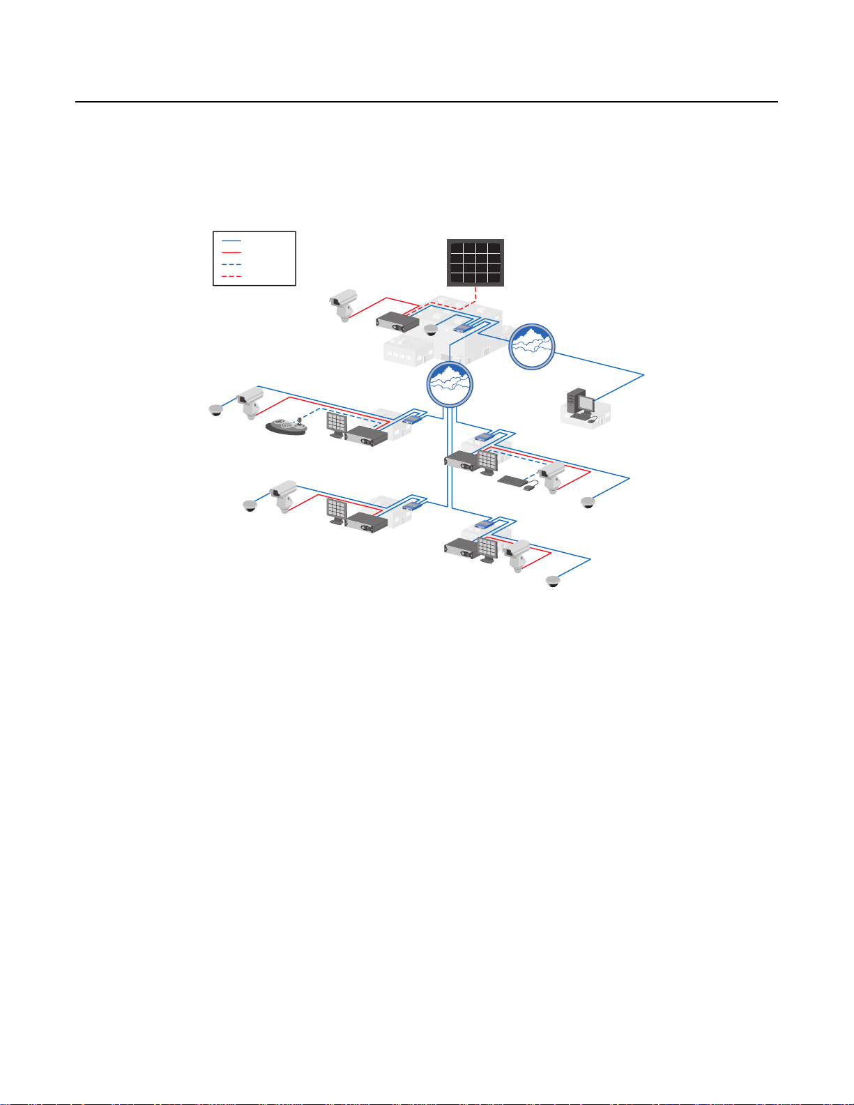
IMPORTANT NOTE: PLEASE READ. The network implementation is shown as a general representation only and is not intended to show a
detailed network topology. Your actual network will differ, requiring changes or perhaps additional network equipment to accommodate the
system as illustrated. Please contact your local Pelco representative to discuss your specific requirements. As shown above, one DVR5100
Remote Client application can access one DVR at a time. Each DVR5100 can support up to five simultaneous remote client connections.
DVR5100
DVR5100
16 CAMERA VIEWS
IP
LAN
DVR5100
DVR5100
WAN/LAN
USB KEYBOARD
AND MOUSE
REMOTE CLIENT
IP
IP
Figure 1. DVR5100 Network Diagram
The hybrid capability of the DVR5100 offers a cost-effective way to service existing analog cameras, while providing expansion through the use
of new IP cameras. By leveraging ubiquitous IP networks and taking advantage of technologies such as Power over Ethernet (PoE), IP cameras
provide an attractive alternative to deploying analog cameras. The DVR5100 Series supports the following camera options:
• DVR5104: Records 4 analog cameras and up to 16 IP cameras.
• DVR5108: Records 8 analog cameras and up to 12 IP cameras.
• DVR5116: Records 16 analog cameras and up to 4 IP cameras.
The DVR5100 supports a wide array of Pelco IP cameras. With the ability to record analo g and IP cameras, systems can be designed to service
existing cameras while laying the groundwork for future expansion.
The DVR5100 server-to-server capability can create a virtual security room. Up to five DVRs can be networked together across a LAN. With
predefined rights and permissions, users can log on to any DVR o n the network and access all cameras and options granted to them, regardless
of the DVR to which the cameras are connected. Finally, a remote client connection to one of the DVRs on the network will provide access to all
DVRs configured in the server-to-server mode. A virtual matrix of up to 100 cameras can be configured easily to support the needs of a given site.
system integration creates a second, more powerful growth path for DVR users. The DVR5100 can easily become a systemized component
Endura
of the Endura system. When integrated, the DVR5100 will continue to provide local access to its cameras. In addition, an Endura workstation,
decoder, or VCD5000, can monitor and control any camera, alarm, or relay connected to any DVR5100 in a full virtual matrix application.
DVR5100s are administered and managed through the Endura workstation: user rights and permissions can be established at each DVR5100 for
local access.
C1696M-A (7/08) 7
Page 8

The DVR5100 features innovative configuration options and tools that can significantly decrease the amount of time and effo rt required to deploy
a unit. Connect the supplied USB keyboard and mouse to the DVR5100 and configuration becomes as easy as a Windows®-based DVR. Take
advantage of carefully laid out menus to intuitively navigate through the configuration process. Leverage the built-in storage estimator and
automatic camera configuration optio ns to instantly program the DVR’s recording behavior in support of a required retention target.
Convenient front panel controls, combined with a heads-u p icon-based user interface, make operating the DVR5100 easy. The icon-based user
interface and color coordinated f unction keys on the fro nt pa nel help to reduce the learning curve. The USB keyboard, mouse, and the front panel
controls, allow operation of Pelco pan/tilt/zoom (PTZ) cameras through either Coaxit ron
®
, Pelco D, or Pelco P protocols. Live video can be paused,
rewound, or fast-forwarded with the push of a button. A single-button operation opens search screens that allow near instant access to video
that is required for investigations. A single-button export feature simplifies the exporting of digitally signed video, along with the player, onto the
included CD/DVD writer or user-supplied USB memory device.
The DVR5100 delivers enterprise-class video reco rding performa nce to the mainstre am DVR market. To support high-per formance, wh ile keeping
the total cost of ownership within budget constraints, the DVR51 00 uses the EnduraStor
™
storage optimization technology. EnduraStor allows
video, recorded at higher frame rates, to be reduced to a lower rate after a user-defined period of time. This saves valuable hard disk drive space
and makes real time video available for search, playback, and export during the delay period. Instead of reverting to time-lapse recording to
achieve longer retention periods, EnduraStor records and retains real-time video for the designated delay period. Alarm or event video is
automatically saved at the higher recorded rate. EnduraSto r makes real-time video available when you need it most, while keeping storage costs
under control.
Flexible view options allow you to display superior video on a variety of monitors. Video can be displayed on NTSC/PAL composite, NTSC/PAL,
S-Video, or VGA monitors. The main monitor can display 1, 4, 9, or 16 images. Live and playback video can be combined on the same monitor
simultaneously, allowing you to observe the scene while conducting a search on recorded video. In addition, a programmable sequence monitor
provides a sequencing display for the analog cameras to a composite monitor.
For remote viewing and administration, the DVR5100 provides unparalleled sophistication and flexibility. Designed to protect the system and
sensitive video content from unauthor ize d access, remote access is tightly controlled and protected through a built-in VPN server. The free
remote client software provides bandwidth throttling upon each connection to the DVR. Clients with limited Internet speed will not impact users
with more bandwidth if all connect to the DVR at the same time. The remote client adds additional sophistication to the DVR5100. Custom user
profiles can be created on the remote client that provide extremely fine granularity on user rights and permissions. Event groups can be created
that incorporate multiple alarm conditions, providing an effective means of filtering out potential false alarms. Finally, complex scripts can be
written that coordinate the response of the D VR to a given alarm or event trigger.
The combination of enterprise-class recording performance, cutting-edge storage optimization technologies, efficient and intuitive configuration
and operation, and flexible upgrade paths that enhance the ROI, make the DVR5100 the ideal solution for retail, finance, education, corporate,
and commercial security applications.
NOTE: The DVR5100 can operate as a stand-alone or networked device. If the DVR5100 is going to be included in an existing network, al ways
include your network administrator when planning and installing the DVR5100.
NEW PRODUCT FEATURES
The DVR5100 Series 1.5 release has been enhanced with the following new featu res:
Table A. New and Enhanced DVR5100 Features
New Feature Description
Modified User Interface
IP Camera Recording
Capability
Server-to-Server
Capability
Integration with Endura
Systems
8 C1696M-A (7/08)
New menus and options make configurat ion and op eration easier and m ore intuitive. In addition, th e system can
be operated through the included USB PC keyboard and mouse.
The DVR5100 Series now supports hybrid recording capability. Each DVR5100 can support up to 20 cameras,
with 4, 8, or 16 (depending on the model) analog cameras and the balance made up of IP cameras.
Server-to-server capability a llo ws up to five DVR5100s to be networked together on a LAN in a virtual matrix
configuration. With server-to-server, any DVR5100 monitor can be used to access, search, and control up to a
100-camera system.
The DVR5100 can also be integrated into an Endura network by an Endura-certified integrator.
Page 9
Getting Started
This manual describes how to operate the DVR5100 to view and record live video, search for recorded video and mark or lock it for future use,
and to operate or adjust cameras. For information on installing and configuring the unit, refer to the DVR5100 Series Hybrid Video Recorder
Installation manual (C1695M). Refer to Appendix A: Front Panel Indicators on page48 for detailed information on the DVR5100 front panel.
LOGGING ON
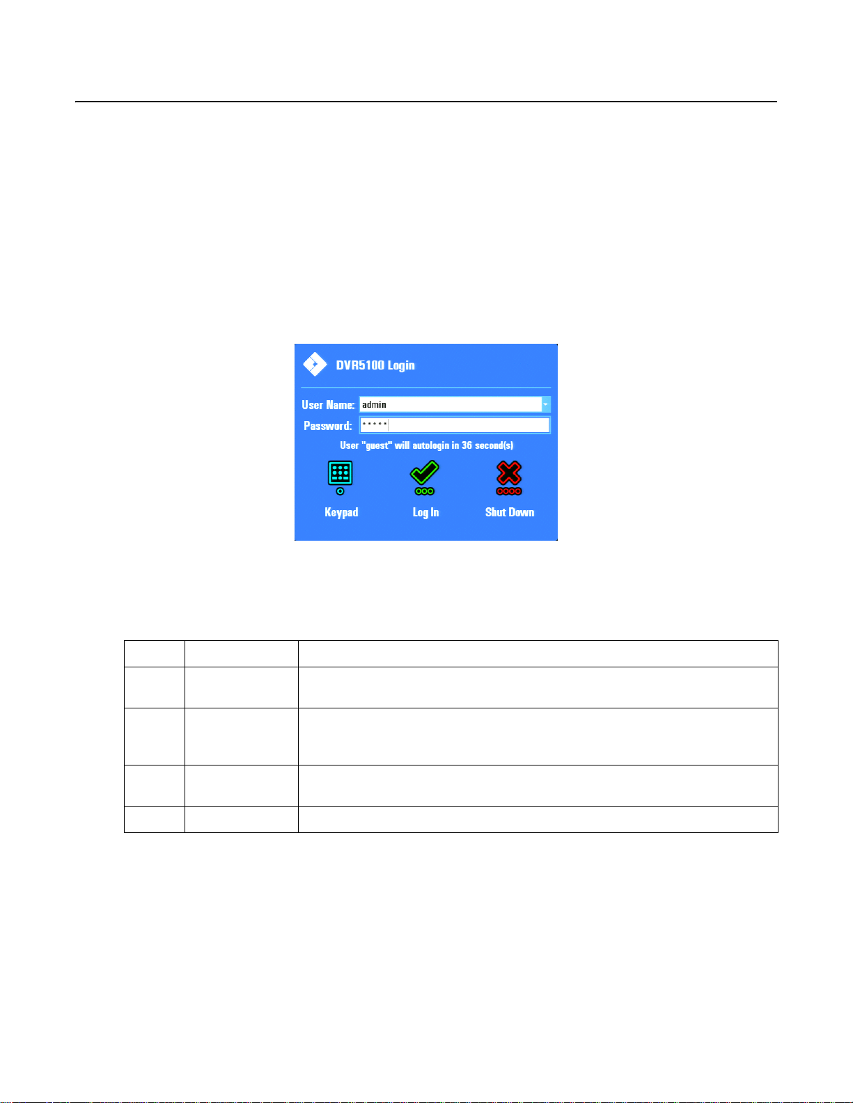
AUTOLOGIN
Each time you start the DVR5100, the system automatically begins a 60-second counter. This feature allows the system to automatically log on
the designated user each time the DVR is rebooted (for example, after a power failure or when the unit is restarted for any reason). An
administrator can enable or disable the autologin feature fr om the Gen eral System setu p screen. In addition , the user accoun t and the timing can
be changed for subsequent autologins. Once the time co unts down to zero, the designated user is logged on. To interrupt the autologin process or
log on as a different user, follow the steps below. The default user is “admin.”
Figure 2. Autologin Dialog Box
T ableB lists the default user IDs, passwords, and role descriptions.
Table B. Default User IDs and Passwords
User ID Password Role Description
admin admin or 23646
manager manager or 6262437
operator operator or 67372867
guest guest or 48378 The Guest can monitor live video and audio, change layouts, and reposition PTZ cameras.
NOTE: Contact your DVR5100 system administrator to set up additional users and roles, or to obtain help with passwords.
The Administrator can access all of the DVR5100 features and is the only user level with permission to
modify every option and value in the Setup page.
The Manager can monitor live video and audio, reposition PTZ cameras, respond to alarms, run scripts,
activate relays, search for video, play it back, lock clips, capture snapshots, export video, and view all of
the Setup windows.
The Operator can monitor live video and audio, reposi tion PTZ cameras, respond to alarms, run scripts,
activate relays, and search for and play back video.
LOGGING ON WITH THE KEYBOARD AND MOUSE
To log on using the keyboard and mouse:
1. Select a user from the User ID list.
2. Click in the Password box, and then type the password.
3. Click Log In to accept the user name and password. If the password is correct, the DVR5100 displays the main application window.
C1696M-A (7/08) 9
Page 10
LOGGING ON WITH THE CONTROL PAD
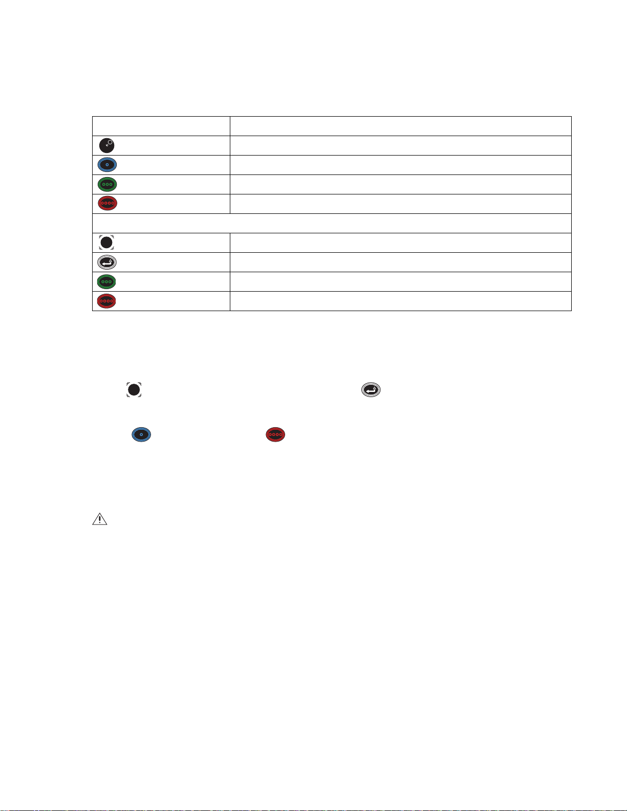
TableC provides control pad functions at login if a keyboard and mouse are not connected.
Table C. Special Login Controls
Control Pad Functions
Jog (inner dial) Cycles through the list of users (by default, the options are admin, guest, manag er, and operator).
Blue function button Press to display the on-screen password keypad. (Refer to the keypad instructions in this table.)
Green function button Press to log on to the DVR5100 once the password is entered.
Red function button Press to shut down the DVR5100 once the password is entered.
When on-screen password keypad is open:
Joystick Navigates up, down, left, and right through the keypad's number grid.
Enter/Shift Enters the currently selected number into the password box.
Green function button Saves the entered password, and then closes the keypad.
Red function button Clears the entered password, and then closes the keypad.
T o log on using the control pad:
1. Turn the Jog (inner dial) to select the user name.
2. Press the blue function button. The on-screen keyboard appears.
3. Use to navigate to the first number of your password, and then press .
4. Repeat these steps until you have entered the entire password.
5. Press to accept the password, or press to cancel the password and return to the Login dialog box.
6. From the Login dialog box, select Log In to accept the user name and password.
SHUTTING DOWN
WARNING: Do not shut down the DVR5100 by turning off the power. Doing so can cause data loss or may corrupt the database. Always
follow the procedures in this section to turn off the unit.
Use the following steps to shut down the DVR5100. For security purposes, the DVR5100 can be shut down only if you have Administrator level
permissions.
1. From the Login screen, select the admin user ID, and then enter the appropriate admin password.
2. Select Shut Down to power off the system.
3. If you are already logged on, use the on-screen menus to log off and follow the steps above (refer to Understanding DVR5100 Controls and
Menus on page 12).
4. The DVR5100 saves all configuration information and recorded video, and then shuts down.
10 C1696M-A (7/08)
Page 11

LOGGING OFF
You can log off from the system without shutting down the unit. This allows the DVR5100 to continue recording while preventing unauthorized
access to the unit.
NOTE: Autologin must be disabled to log off from the system without shutting down the unit. With autologin disabled, the Login dialog box
remains on the screen and you or another operator can log back on to the system. While you are logged off, the system continues to record as
configured.
To log off:
• From the Main menu, click Logout . The Login dialog box appears and the system closes your work session.
• If you do not have a mouse, use the Joystick to navigate to Logout, and then press Enter/Shift .
C1696M-A (7/08) 11
Page 12
Understanding DVR5100 Controls and Menus
The DVR5100 is menu-driven and you can operate the unit using any of the following options:
• USB PC keyboard and mouse: A USB PC keyboard and mouse are n ow provided to operate the DVR5100, which is the easiest means to
operate the unit. A template is included to provide a quick reference for all available keyboard shortcuts (refer to Figure 3).
Figure 3. USB PC Keyboard Template
• DVR5100 control pad: If it is not convenient to use a USB PC keyboard and mouse for your insta llation, you can use the front panel
controls to operate the DVR5100.
NOTES:
• Directions for configuring and operating the DVR5100 are given for the USB PC keyboard and mouse, and the control pad. Throughout
this document, the first part of the instructions refer to the keyboard and mouse, followed by instructions in brackets ([ ]) for the control
pad.
• Refer to Table D on page 14 through Table G on page 16 for detailed functional descriptions of the DVR5100 control pad.
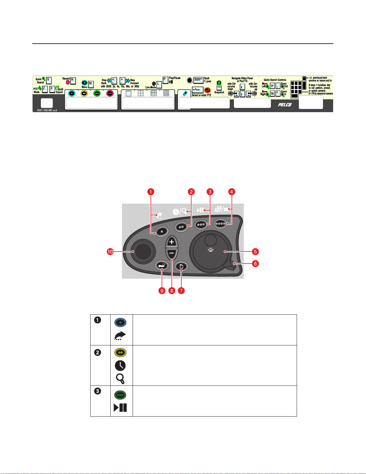
Figure 4. DVR5100 Front Panel Control Pad
Blue Function Button:
• Active when on-screen menus are displayed (selects blue menu items).
• “Quick Export” when on-screen menus are not displaye d.
Yellow Fun ction Button:
• Active when on-screen menus are displayed (selects yellow menu items).
• “Go to live” when on-screen menus are not displayed.
• Press and hold for Quick Search when on-screen menus are not displayed.
Green Function Button:
• Active when on-screen menus are displayed (selects green menu items).
• “Play/Pause” when on-screen menus are not displayed.
12 C1696M-A (7/08)
Page 13
• DVR5100 remote client: For advanced programming and remote access, use the DVR5100 remote client application. Refer to the
DVR5100 Remote Client Operation manual (C1697M) for more information.
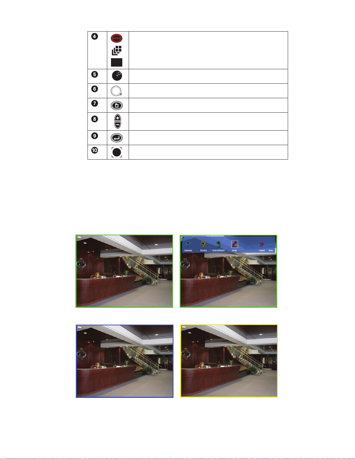
APPLICATION MODES
Figure 5 illustrates the various application modes (live view, menu, PTZ, and playback). For example, when you are in live view mode, the video
pane is surrounded by a green border.
Red Function Button:
• Active when on-screen menus are displayed (selects red menu items).
• “Change layout” when on-screen menus are not displayed.
• Press and hold for full screen when menus are not displayed.
Jog (inner dial)
Shuttle (outer ring)
Menu
Plus (+)/Minus (–) buttons
Enter/Shift
Joystick
Live View Mode
PTZ Mode
Menu Mode
Playback Mode
Figure 5. Video Pane Modes
C1696M-A (7/08) 13
Page 14
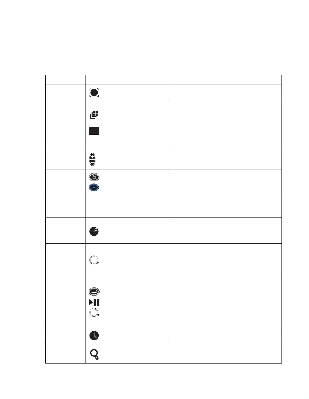
USB PC KEYBOARD/MOUSE AND CONTROL PAD FUNCTIONS
Table D describes the USB PC keyboard and mouse, and DVR5100 front panel controls that are available when you vie w live or recorded video,
with no on-screen menus visible. Live video is indicated by a green border and recorded video is indicated by a yellow border; and PTZ mode is
indicated by a blue border. Refer to TableE on page 15 for information on the front panel controls for PTZ mode.
NOTE: The Main menu can only be accessed in live view mode.
Table D. Live and Playback Controls (1 of 2)
Keyboard Control Pad Function
Right, Left, Up, and
Down Arrows
F5–F8 Change layout
Plus (+)/Minus (-) Plus (+)/Minus (-)
Numeric keypad + F9
O (zero) + F9 N/A
< or , (comma)
> or . (period)
Joystick Navigates to a different video pane.
Menu +
Blue function + Blue function
Jog (inner dial)
Keyboard: Press F5 (1 x 1), F6 (2 x 2), F7 (3 x 3), and F8 (4 x 4) to
change the screen layout. Left-click twice to change to a full
screen configuration.
Control pad:
• Press “Change layout” to toggle the screen layout from
1 x 1, 2 x 2, 3 x 3, and 4 x 4 display layouts.
• Press and hold “Change layout” to jump straight to single/
full-screen video for the currently sele cted camera.
Press plus (+) to display the next camera in the sequence in the
currently selected video pane.
Press minus (-) to display the previous camera in the sequence.
Keyboard: Type the desired camera number, and then press F9 to
jump directly to that camera.
Control pad: Opens the Camera Selection dialog so that you can
choose a specific camera without cycling through the sequence.
• Type 0 (zero), and then press F9 to disconnect a ca mera.
• Right-click in a video pane (live view mode) for the shortcut
menu, and then click Disconnect.
Keyboard: Press < or , (comma) to step backward or > or . (period)
to step forward.
Control pad: Turn the Jog (inner dial) counterclockwise to step
backward or clockwise to step forward.
Keyboard: Press < or , (comma) for fast rewind, > or . (period) for
< or , (comma)
> or . (period)
Shift + < or , (comma)
Shift + > or . (period)
L Go to live
S Quick Search
14 C1696M-A (7/08)
Shuttle (outer ring)
Enter/Shift
Play/Pause
Shuttle (outer ring)
fast forward.
Control pad: Turn the Shuttle (outer ring) counterclockwise for
fast rewind, clockwise for fast forward. To increase speed, turn
the Shuttle (outer ring) further in the desir ed direction.
Keyboard: Press the Shift key while repeatedly pressing < o r,
(comma) > or . (period) to rewind or fast-forward to lock in the
current speed (2x, 4x, 15x, 60x, or 300x). Press P to cancel the
speed setting.
Control pad: Press Enter/Shift while using the Shuttle (outer
ring) to rewind or fast-forward to lock in the current speed (2x, 4x,
15x, 60x, or 300x). Press “Play/Pause” or turn the Shuttle (outer
ring) to cancel the speed setting.
Press L or “Go to live” to switch from viewing recorded video to
viewing live video from the currently selected camera.
Keyboard: Press S to open the Quick Search dialog box.
Control pad: Press and hold the Quick Search function button for
3 seconds to open the Quick Search dialog box.
Page 15
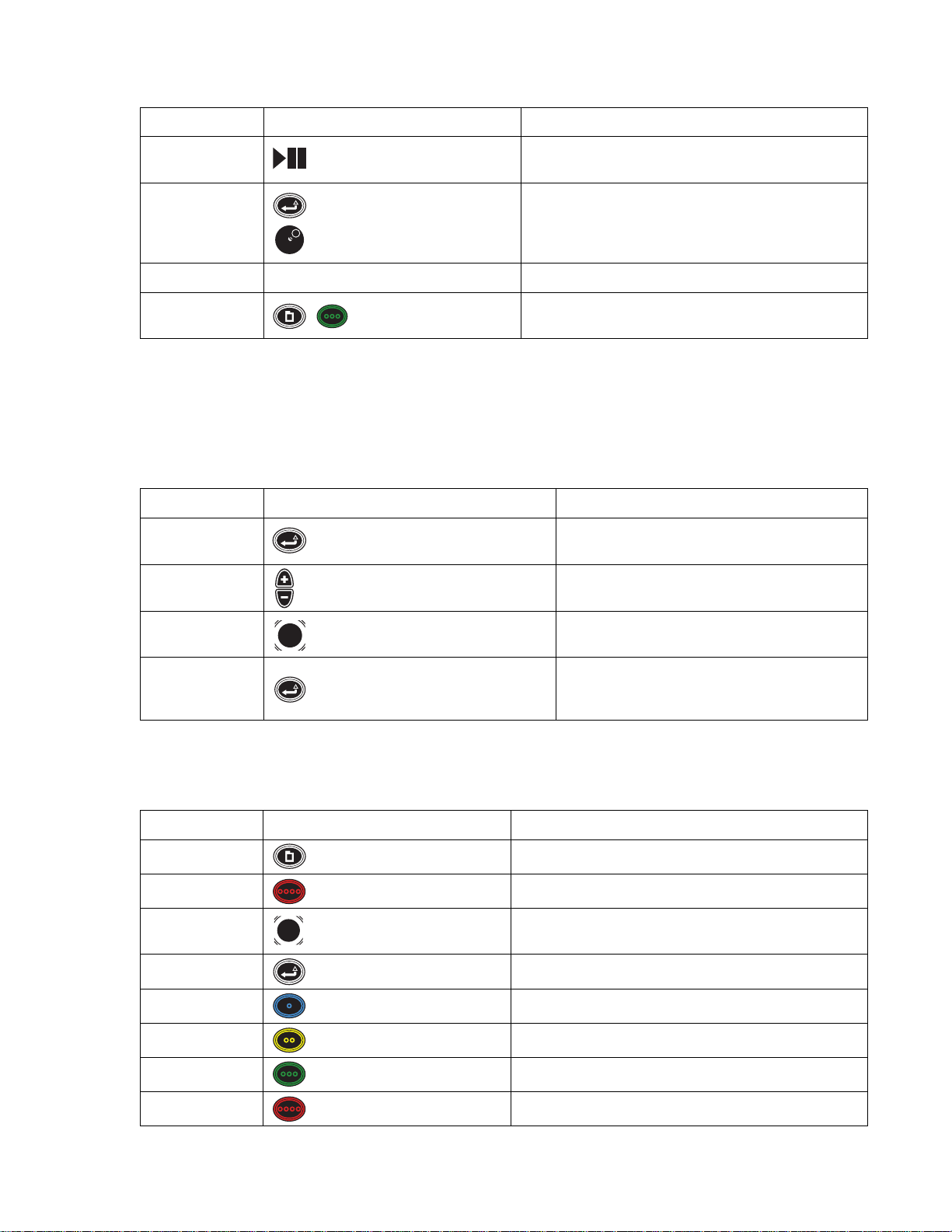
Table D. Live and Playback Controls (2 of 2)
Keyboard Control Pad Function
P Play/Pause
Press P or Play/Pause to toggle between play back and pause. You
can press P or Play/Pause while viewing live video.
Keyboard: Press Ctrl + the left or right arrow to turn the volume
Ctrl + Left arrow,
Ctrl + Right arrow
Enter/Shift +
Jog (inner dial)
up or down.
Control pad: Press and hold Enter/Shift while turning the Jog
(inner dial) to adjust the volume.
R N/A Starts or stops recording in the currently selected video pane.
Print Scrn
Menu + Green function +
Green function
Captures a snapshot (still video image) and saves it to a USB
memory device.
T ableE describes the keyboard and front panel controls that are available when controlling PTZ on a selected camera, when no on-screen menus
are visible. Press Enter/Shift to enter PTZ mode, which is indicated by a blue border around the currently selected video pane. Y ou cannot change
cameras or navigate to a different video pane in this mode.
NOTE: You must be in live mode to activate PTZ. You cannot activate PTZ while in video playback.
Table E. PTZ Controls
Keyboard Control Pad Function
Z or Enter Enter/Shift
Plus (+) and Minus (-)
Plus (+)/Minus (-) buttons
Press and release to enter or exit PTZ mode.
Press plus (+) to zoom in.
Press minus (-) to zoom out.
Right, Left, Up, Down
Arrows
Joystick Controls the PTZ camera pan (right/left) and tilt (up/down).
In PTZ mode, press Z or Enter [or Enter/Shift] to
Z or Enter Enter/Shift
automatically switch the selected camera back to live or
playback mode.
TableF describes the keyboard and front panel controls available when a menu or dialog is on the screen (Menu mode).
Table F. Menu Controls (1 of 2)
Keyboard Control Pad Function
M
Esc (Escape)
Ta b, Right/Left
arrow
Enter
F1
F2
F3
Menu Shows or hides on-screen menus.
Red function button Closes the current dialog box
Joystick Moves to the next item in a menu or field in a dialog
Enter/Shift Selects currently selected menu item
Blue function button Selects the blue item on the current menu or dialog.
Yellow function button Selects the yellow item on the current menu or dialog.
Green function button Selects the green item on the current menu or dialog.
F4
C1696M-A (7/08) 15
Red function button Selects the red item on the current menu or dialog.
Page 16

Table F. Menu Controls (2 of 2)
Keyboard Control Pad Function
Up/down arrow,
Page up/down
Backspace Shuttle (outer ring)
Plus (+) and Minus (-) Plus (+)/Minus (-) buttons
Jog (inner dial) Scrolls through different options in a list or drop-down menu.
Backs up one menu level. If a text field is selected, this function
moves the cursor through the letters in the field.
In a number field, plus (+) to increases the value. Press minus (-) to
decrease the value of a number.
Use any alphanumeric key on the keyboard to enter information in a
text box such as a password, IP address, comment, or other field.
Do not enter characters that are not valid for the currently selected
field. Refer to the specific field instructions for guidelines on valid
entries. Refer to the descriptions in this table for additional
Alphanumeric
keypad
Blue function button +
Jog (inner dial) [for Keypad
only]
functions for specific characters.
T ableG describes the keyboard and front panel controls available when using the Quick Search dialog.
T able G. Quick Search and Export Controls
Keyboard Control Pad Function
Keyboard: Press S to open the Quick Search dialog box.
Control Pad: Press and hold the Quick Search function button for
S Quick Search
3 seconds to open the Quick Search dialog box.
NOTE: You can also open Quick Search by navigating thro ugh th e
menus: Menu + green function button + blue function button.
Right or Left Arrows,
Page Up, Page Down
Plus (+) and Minus (-)
Jog (inner dial)
X Quick Export
MMenu
Jog (inner dial) Moves the time line slider to the right or the left.
Plus (+)/Minus (-) buttons Keyboard/Control Pad: Press Plus or Minus to zoom in or out on
the Quick Search time line. Zoom levels are year, month, week,
day, hour, minute, and second.
Control Pad: Rotate the Jog (inner dial) to move the time line
Shuttle (outer ring)
cursor to the right or left. Rotate the Shuttle (outer ring) to zoom in
or out on the time line.
Displays or hides the Quick Export menu. Options include Export
Video, Mark, and Snapshot.
From the Quick Search dialog box, view more Quick Search
options.
16 C1696M-A (7/08)
Page 17

DISPLAYING AND HIDING THE SYSTEM MENUS
Once logged on, press the “M” key [or Menu ] to display and hide the on-screen menus. Refer to Figure 12 to view the Main menu
hierarchy.
Figure 6. DVR5100 Main Menu
NAVIGATING TO AND SELECTING A MENU ITEM
USB KEYBOARD/MOUSE
T o select a menu item using the USB PC keyboard/mouse:
1. Click the item with your mouse, or use the right or left arrow key, and then press Enter. The yellow cursor denotes the selected menu item.
2. You can also select o ne of the four colored-coded icons by pressing F1 (blue), F2 (yellow), F3 (green), or F4 (red).
3. Click the Back icon to return to a previous menu.
CONTROL PAD
Opening or Closing a Menu
1. To open an on-screen menu, press . The on-screen menu you were previously using appears.
2. To close an on-screen menu, press . The on-screen menu disappears.
Navigating to a Menu Item
1. Use the Joystick to move left or right to a menu item. The yellow cursor denote s the selected menu item.
2. Press Enter/Shift
to select the selected menu item.
Selecting a Menu Item
The DVR5100 control pad contains four color-coded function keys. The color of each button corresponds to the on-screen menu items displayed in
the DVR5100 menus, screens, and dialog boxes. This color-matching design lets you navigate the on-screen menus without looking down to read
keyboard text labels. The colors always appear in the same order from left to right: blue, yellow, green, and red.
Figure 7. Control Pad Color-Coded Function Keys
Press the color-coded function button that corresponds to the on-screen menu item. For example, to select the blue icon on the screen, press the
blue function button on the DVR5100 control pad.
C1696M-A (7/08) 17
Page 18

Returning to a Previous Menu
There are three ways to return to a previous or higher level menu: To return to a previous menu, tap the Joystick to the on-screen Back icon, and
then press Enter/Shift .
• T urn the Jog (inner dial) to the right or left until you select the Back icon on the screen, and then press Enter/Shift.
• Move to the on-screen Back icon, and then press Enter/Shift.
• Turn counterclockwise.
The icon path at the top of the menu bar tells you which menu icon you selected to arrive at your current location.
Figure 8. Sample Icon Path
SHOWING AND HIDING ONLINE HELP FOR THE CONTROL PAD
To open the Help dialog box:
1. Open the Main menu.
2. Select Help. The Help & Information dialog box appears (refer to Figure 9).
Figure 9. Help Menu
3. Click Help. The DVR5100 online Help dialog box for the control pad appears.
[Or, select Help, and then press Enter/Shift , or press the blue function button .]
Figure 10. Control Pad Online Help Dialog Box
4. Press any key to hide the online Help dialog box.
18 C1696M-A (7/08)
Page 19

SHOWING SYSTEM INFORMATION
The System Information screen provides details that are useful for troubleshooting your unit and for communicating with the Pelco Product
Support team.
To open the System Information dialog box:
1. Open the Main menu.
2. Click Help [or press the yellow function button ] (refer to Figure 9). The Help & Information dialog box appears.
3. Click System Info. The DVR5100 System Information dialog box appears.
[Or, press the blue function button , and then press Enter/Shift .]
4. Select OK after reviewing this information.
ON-SCREEN MENUS
The DVR5100 on-screen menu hierarchy presents only those menus for which you have permission. Depending on your user role, you might see
all available menus or only a few. The default user roles are Administrator, Manager, Operator, and Guest. The menu descriptions in this section
are based on the Administrator role, which has access to all menus and functions. Figure 12 shows the DVR5100 menu hierarchy.
NOTE: Contact your system administrator if you need authorization to access additional menus.
Figure 11. System Information
Figure 12. DVR5100 Menu Hierarchy
C1696M-A (7/08) 19
Page 20

SHORTCUT MENUS
Some DVR5100 functions are available through shortcut menus. Right-click in any part of the application window to access the shortcut menus
for that location. Figure 13 shows an example of a shortcut menu and submenus. Other shortcut menus are discussed in Operating the DVR5100
on page21 and Working with Cameras on page42.
Figure 13. Shortcut Menu and Submenus
SUBMENUS
Shortcut menus may have one or more items with a symbol (!) beside it. The symbol indicates that a menu has additional options. Once the
submenu appears, move your cursor over an item with a symbo l, and then select a submenu item.
To hide the menus and submenus, click another part of the video pane .
20 C1696M-A (7/08)
Page 21

Operating the DVR5100
The USB keyboard and mouse, and the DVR5100 control pad, provide access to most DVR5100 features and functionality.
MONITORING LIVE VIDEO
The DVR5100 starts in live video mode. The following information describes how to work in this mode.
NOTE: Video panes display the cameras and layouts selected from the last login.
SELECTING A VIDEO PANE
When you start the unit and display a layout with several vide o panes, the upper left video pane is selected by default. To select a different video
pane, click in another video pane with the mouse, or use the keyboard arrow keys [or the Joystick ] to move left, right, up, and do wn. Th e
border of the currently selected video pane changes color to r eflect the current operating state of the DVR5100.
• Green: Indicates the camera is in live view mode (currently selected video screen).
• Yellow: Indicates the camera is in playback mode.
• Blue: Indicates that PTZ mode is enabled in the video pane.
• Red: Indicates that manual recording is in progress in the video pane.
CHANGING SCREEN LAYOUT
The screen layout can be changed by pressing the F5–F8 keys. [Or, each time the Change Layout function button is pressed, one of four screen
layouts is displayed].
• Full-screen view (1 x 1): Press F5 [or “Change layout”] to display a single video pane. You can also double-click the left mouse
button in the live view mode pane for a full-screen configuration.
• Four-camera view (2 x 2): Press F6 [or “Change layout”] to display 4 video panes in rows of two.
• Nine-camera view (3 x 3): Press F7 [or “Change layout”] to display 9 video panes in rows of three.
• Sixteen-camera view (4 x 4): Press F8 [or “Change layout”] to display 16 video panes in rows of four.
VIEWING A SPECIFIC CAMERA
When you select a camera, its video stream is sent to the currently selected video pane. For example, if your display is set to a 2 x 2 layout and
the upper left video pane is selected, you can choose an y camera to display in that vid eo pane. Follow th e instructions below t o move through the
camera sequence, call up cameras by number, and disconnect cameras.
Figure 14. Displaying Video in a 2 x 2 Configuration
C1696M-A (7/08) 21
Page 22

MOVING THROUGH THE CAMERA SEQUENCE
Although a camera is displayed in a specific video pane, you can quickly cycle through the list of cameras in the sequence.
To sequence through the list of cameras:
1. Select the video pane displaying the desired camera.
Figure 15. Displaying a Camera in a Video Pane
2. Press Plus (+) on the keyboard’s numeric keypad [or ] to view the next camera in the sequence. Press Minus (-) [or ]to view the
previous camera in the video pane sequence.
CALLING UP CAMERAS BY NUMBER
To call up a camera by a logical number (keyboard only):
1. Select the video pane to display the desired camera.
2. Type a camera number (the camera must be enabled).
3. Press F9. The camera is displayed in the selected video pane.
CALLING UP CAMERAS THROUGH THE CAMERAS MENU
To select a camera through the Cameras menu:
1. Select the desired video pane.
2. Press the “M” key [or ] for the Main menu.
3. Click Cameras [or select Cameras, and then press ]. The Cameras menu appears.
Figure 16. Cameras Menu
22 C1696M-A (7/08)
Page 23

4. Click Select Camera [or move to Select Camera using the Joystick , and then press Enter/Shift ]. The Camera List opens (refer
to Figure 17).
Figure 17. Camera List
5. Select the desired camera, and then click OK. [Or, navigate to a camera using the Jog (inner dial) , and then press Enter/Shift ].
Video from the camera is displayed in the selected video pane.
NOTE: A red slash through a camera icon in the list indicates that it is currently not available for display.
DISCONNECTING CAMERAS
When you disconnect a camera, the video disappears from the video pane and the audio stream (if any) is disconnected.
NOTE: Disconnecting a camera does not affect its recording status. Even though a camera is not being viewed, it is still recording if it has an
active recording schedule.
To disconnect a camera by number (keyboard only):
1. Navigate to the video pane displaying the desired camera.
2. Press 0 (zero), and then press F9. The camera is disconnected.
T o disconnect a camera through a shortcut menu (mouse only):
1. Right-click in the selected video pane. A shortcut menu appears.
2. Select Disconnect. The camera is disconnected and video disappears from the video pane.
C1696M-A (7/08) 23
Page 24

PTZ Operations
REPOSITIONING A CAMERA WITH PTZ CAPABILITIES
If you have a camera that supports PTZ operations, you can reposition the camera with the keyboard [or the Joystick ].
NOTE: With a mouse, you can reposition a camera in both live view and PTZ mode (the camera must support PTZ).
The border surrounding a camera switches from green to blue in PTZ mode. In this mode, access to on-screen menus is disabled and the mouse,
Joystick , and Plus (+) and Minus (-) perform PTZ operations. In addition to controlling a PTZ camera manually, you can reposition the camera
based on predefined patterns, presets, and scan operations. Refer to Using Patterns, Presets, and Scans on page 25 for more information.
NOTE: You do not need to be in PTZ mode to run patterns, presets, or scans.
T o reposition a camera:
1. Navigate to the video pane displaying the desired camera. The selected video pane should be in live mode, which is indicated by a green
border.
2. Click in the video pane [or press Enter/Shift ]. The border around the video pane changes to blue.
Figure 18. PTZ Mode Indicated by Blue Border
3. Use the following options to operate in PTZ mode :
a. Mouse: Click in the video pan e and move the mouse to pan right, left, up, and down in the current scene. Roll the mouse wheel
towards the screen to zoom in, and away from the screen to zoom out.
b. Keyboard: Press the left or right arrow to pan to the left or right of the current scene, and the up or down arrow to pan up or down.
Press and hold Plus or Minus to zoom into or out of the scene.
c. Control Pad: Use the Joystick
(-) to zoom into or out of the scene.
4. Press Enter [or Enter/Shift ] to return to live view mode.
NOTE: If the camera does not respond to the arrow keys or Joystick , verify that the camera protocol is configured correctly. The DVR5100
supports Coaxitron, Extended Coaxitron, Pelco D, and Pelco P protocols for cameras with PTZ control.
24 C1696M-A (7/08)
to tilt the camera up, down, right, or left in the current scene. Press and hold Plus (+) or Minus
Page 25

USING SHORTCUT CONTROLS FOR PTZ OPERATIONS
PAN TO ZERO
To pan the camera back to its zero position:
1. Right-click the video pane to display the shortcut menu.
2. Select Operations.
3. Select “Pan to Zero.” The camera is repositioned at its zero position. This position is determined by the position of the camera at
installation.
.
Figure 19. Pan to Zero
ROTATE THE CAMERA
To rotate the camera 180 degrees:
1. Right click in the video pane to display the shortcut menu.
2. Select Operations.
3. Select Rotate 180 Degrees.
USING PATTERNS, PRESETS, AND SCANS
The DVR5100 allows you to activate patterns, presets, and scans, which can be activated automatically or manually from the DVR5100. Patterns
and presets must be programmed by the system administrator before they can be executed.
PATTERNS
A pattern is a user-defined, viewable camera path with a beginning and end. The number and duration of patterns varies with different
positioning systems. Refer to documentation for your cameras to determine the number of patterns that may be configured.
Programming a Pattern
To program a PTZ pattern using an on-screen shortcut menu:
1. While in live view mode, right-click in a video pane that is displaying video from a camera with PTZ capabilities. A shortcut menu appears.
2. Click Pattern > Record Pattern > Modify Pattern. The M odify Pattern screen appears (refer to Figure20).
C1696M-A (7/08) 25
Page 26

Figure 20. Selecting a Pattern
3. Enter the pattern number you want to modify, and then click OK.
4. Use PTZ controls to move the camera through the pattern of movements you want to record.
5. Right-click in the video pane, and then click Record Pattern > End Record.
Running a Pattern
To run a PTZ pattern using a keyboard/mouse or DVR5100 control pad:
1. From the Main menu, click Actions. [Or, navigate to Actions, and then press Enter/Shift .]
The Actions menu appears.
2. From the Actions menu, click PTZ Operations. [Or, navigate to PTZ Operations, and then press Enter/Shift .]
The PTZ Operations dialog box appears (refer to Figure 21).
Figure 21. PTZ Operations Dialog Box
3. Click in the text field, and then type a pattern number.
[Or, navigate to the text field, and then press Plus or Minus until the pattern number appears.]
4. Click Patterns [or press the blue function button ]. The pattern starts.
5. To exit the dialog box without activating the pattern, click Close [or press th e red function button .]
26 C1696M-A (7/08)
Page 27

Stopping a Pattern
To stop a PTZ pattern using a keyboard and mouse, or the DVR5100 control pad:
1. Select the video pane that is displaying video from a camera running a PTZ pattern.
2. If the border of the selected video pane is green, press Enter [or Enter/Shift ]. The border color changes to blue.
3. Press the keyboard arrow keys [or move the Joystick ] in any direction. The pattern stops.
To stop a PTZ pattern using the on-screen shortcut menu (mouse only):
1. Right-click in the video pane of the desired camera.
2. Click Pattern > Stop Pattern.
Figure 22. Stopping a Pattern
PRESETS
A preset action forces a camera with PTZ capability to reposition itself on a specific scene (for example, a door).
Recording a Preset
1. Use the PTZ controls to move the camera to the preset position you want to record.
2. Right-click in the video pane of the desired camera. A shortcut- menu appears.
3. Click Preset > Modify Preset. The Modify Preset screen appears.
Figure 23. Modifying a Preset
4. Enter the number of the preset you want to modify and then click OK.
Activating a Preset
T o activate a PTZ preset using a shortcut menu (mouse only):
1. Right-click in the video pane of the desired camera. A shortcut menu appears.
2. Click Preset > Select Preset. The camera is moved to the present lo cation.
To activate a PTZ preset using the keyboard and mouse, or the DVR5100 control pad:
1. While in live view mode, select a video pane that is displaying video from a camera with PTZ capabilities.
C1696M-A (7/08) 27
Page 28

2. From the Main menu, click Actions. [Or, navigate to Actions, and then press Enter/Shift .] The Actions menu appears.
3. From the Actions menu, click PTZ Operations. [Or, navigate to Actions, and then press Enter/Shift .] The PTZ Operations dialog box
appears.
4. In the PTZ Operations dialog box, typ e a numb er in the t ext box, and then click Presets. [Or , navigate to the text field, press Plus or Minus to
select a number, and then press the yellow function button ]. The camera is moved to the preset location.
5. Click Close [or press the red function button ] to close your selection without activating the preset.
SCANS
A scan action moves a camera across the current scene that it is viewing from a predetermined starting point.
Activating Scans
T o activate a scan using the keyboard and mouse, or the DVR5100 control pad:
1. While in live view mode, select a video pane that is displaying video from a camera with PTZ capabilities. The video pane border is green.
2. From the Main menu, click Actions. [Or, navigate to Actions, and then press Enter/Shift .] The Actions menu appears.
3. Click the PTZ Operations icon. [Or, select PTZ Operations, and then press Enter/Shift .] The PTZ Operations dialog box appears.
4. In the PTZ Operations dialog box, type a number in the text field, and then click Scans. [Or, navigate to the text field, press Plus or Minus to
select a number, and then press the green function button ]. The camera scans according to the actions.
5. Click Close [or press the red function button ] to close your selection without activating the preset.
To activate a scan using a shortcut menu:
1. Right-click in the video pane of the desired camera. A shortcut- menu appears.
2. Click Scan. The following options appear:
a. Stop Scan: The scan is stopped.
b. Scan Random: The camera pa ns in an irregular, unsystematic pattern.
c. Scan Frame: The camera scans for 3 seconds, followed by a 3-second pause.
d. Scan Auto: The camera pans continuously.
Figure 24. Scan Shortcut Menu
NOTE: You can re turn to a desired camera view after you select Stop Scan by selecting a Preset position.
28 C1696M-A (7/08)
Page 29

Searching for Recorded Video
The DVR5100 offers two options to search for recorded video:
• Quick Search: Allows you to search for video by camera, date, and time.
• Enhanced Search: Allows you to search for video on multiple cameras, date and time ranges, and can be refined to include only specific
recording types on specific cameras.
QUICK SEARCH
Quick Search provides a simple interface to conduct searches based on time and date for a single camera (by default, the camera you are
viewing). Refer to Commands and Features on page 30 for descriptions of the Quick Search dialog boxes.
PERFORMING A QUICK SEARCH
To perform a quick search and play back video:
1. In live view mode, select a video pane that is displaying video from a camera.
2. From the Main menu, select Search/Export > Quick Search, and then press Enter. [Or, press the Quick Search function button for
3 seconds.] The Quick Search dialog box appears (refer to Figure 25).
NOTE: In live view mode, press the “S” key to bring up the Quick Search dialog box.
3. Click in the time line [or turn the Jog (inner dial) ] to select a starting time. To change the time line display, roll the mouse wheel
towards or away from the screen [or turn the Shuttle (outer ring) ] to zoom in or out on the time line. Units of time increase or
decrease between months and days, days and hours, hours and minutes, or minutes and seconds.
Figure 25. Quick Search Dialog Box
4. Do one of the following:
• To play video and keep the Quick Search dialog box open, select Play.
• To play video and close the Quick Search dialog box, select Play, and then click Close [or press the red function button ].
• To close the Quick Search dialog box without playing ba ck the video, click Close [or press the red function button ].
NOTE: You can select a different camera from the camera list while remaining in the Quick Search screen.
C1696M-A (7/08) 29
Page 30

COMMANDS AND FEATURES
The Quick Search dialog box contains the following commands and features:
Time line: Units of time increase or decrease between months and days, days and hours, hours and minutes, or minutes and seconds. Change
the units of time as follows:
• Zoom in: Roll the mouse wheel towards the screen [or turn the Shu ttle (outer ring) clockwise] to display a smaller unit of time.
• Zoom out: Roll the mouse wheel away from the screen [or turn the Shuttle (out er ring)
time.
Click in the time line to move forward or backward. [You can also turn the Jog (inner dial)
backward along the time line.]
Along with stars that indicate a marked event, the graphical indicator for recorded video has four different colored bars:
Green: Continuous recording
Red: Alarm recording
Blue: Motion recording
Yellow: Manual recording
You can also locate marked or locked video as follows:
Marked Video: The video time line is marked with a star so that certain video can be located easily in a Quick or Enhanced Search.
Locked Video: The video time line shows a white line and brackets that reflect the time range for a locked video clip.
counterclockwise] to display a larger unit of
to the right or left to move forward or
PRIMARY FUNCTIONS
Export: Opens the Export dialog box (refer to Working with Cameras on page 42).
Lock/Unlock Toggle: Locks selected video from being deleted. Locked video left on the storage drives reduces the system storage capacity.
Unlocking video allows it to be overwritten as part of the normal overwrite process. This icon/label changes to Unlock if you move your time line
cursor above a locked clip. If the video clip is large, the cursor may change to a clock during the locking process. A w hite li ne and brackets reflect
the time range for the locked video clip.
T o lock a clip:
1. Move the slider with the mouse [or Jog (inner dial)] to the beginning of the desired period, and then press Lock.
2. Move the slider to the end time, and then press Lock again.
T o unlock a locked clip:
1. Position the slider on the locked clip (white line across the recording bar).
2. Select Unlock.
NOTE: As you set the start and end times, the values are displayed in an information bar that appears at the bottom of the screen.
Play: Starts to play back the video from the cursor position along the time line. The camera, time, and date are displayed above the time line, and
the dialog box remains open.
Close: Closes the Quick Search dialog box. Video contin ues to play if yo u previously pr essed Play . Otherwise, the video pane remains in the same
state as when the Quick Search dialog box was opened.
More: Displays the secondary functions in the Quick Search dialog box (Enhanced Search, Mark, and Snapshot).
SECONDARY FUNCTIONS
Enhanced: Closes the Quick Search dialog box and opens the Enhanced Search dialog box (refer to Enhanced Search on page 31).
Mark: Places a mark on the video so it can be located easily in a Quick or Enhanced Search (refer to Marking an Event on page 35). Mark also
updates the Quick Search graph (indicated by a star), and flashes a message on the information bar to confirm that the marking process is
successful.
Snapshot: Stores a snapshot (a still image) on a USB device using the default snapshot format (refer to Manually Recording Video and Audio on
page 35). A message flashes on the information bar to confirm the capture.
More: Returns you to the primary Quick Search dialog box.
Close: Closes the Quick Search dialog box.
30 C1696M-A (7/08)
Page 31

ENHANCED SEARCH
Use the Enhanced Search dialog box to search for recorded video based on the following search criteria:
• Time Range: Allows you to enter a time ran ge to sea rch for video. To help reduce the number of steps required to access common search
requests, you can also select the past 24 hours, 3 days, or 7 days.
• Cameras: Searches for video recorded on all cameras, multiple cameras, or a single camera.
• Types: Searches for video recorded based on all types, motion detection or alarms, continuous or manual recordings, and locked or marked
video.
PERFORMING AN ENHANCED SEARCH
T o perform an enhanced search:
1. In live view mode, press the “M” key [or Menu] to display the Main menu.
2. From the Main menu, select Search/Export. The Search/Export menu appears.
3. Click Enhanced Search [or navigate to Enhanced Search, and then press Enter/Shift ]. The Enhanced Search dialog box opens.
Figure 26. Search/Export Menu
NOTE: In live view mode, press the “E” key to bring up the Enhanced Search dialog box.
Figure 27. Enhanced Search Dialog Box
4. Click the Time Range box [or navigate to the Time Range box, and then turn the Jog (inner dial)
(“Last 24 hours,” “Last 3 days,” “Last 7 days,” or “Specific time range”).
5. If you select “Specific time range,” you must select a time and date range for the search as follows:
• Keyboard and mouse: Click in the Start and End time and date fields, a nd then type the specific time range. Or, click th e up and down
arrows to select the specific time range.
• Control pad:
– Use the Joystick
– Turn the Jog (inner dial)
– Turn the Shuttle (outer ring)
to navigate between time and date boxes. The first field (hours) is selected by default.
to change the value.
to move to the next field after each change is made.
right or left] to select the time range
C1696M-A (7/08) 31
Page 32

6. Select a camera or cameras from the Cameras list (“All Cameras,” “Multiple cameras,” or individual cameras). If you select
“Multiple cameras,” press Enter [or Enter/Shift ], or select the button next to the Cameras box. The Select Cameras dialog box
opens (refer to Figure 28).
NOTE: By default, all cameras are selected. You must clear the selection for cameras that you do not want to search.
Figure 28. Select Cameras Dialog Box
a. Click the desired cameras [or turn the Jog (inner dial)
b. Click OK when your list is complete [or navigate to OK, and then press Enter/Shift ].
7. Select a video type or types from the Types field (All Types, Multiple Types, Continuous, Motion, Alarms, Manual, Marked, and Locked). If
you select Multiple Types, press Enter [or Enter/Shift ], or select the button next to the Types box. T he Select Search Type
dialog box appears (refer to Figure 29).
NOTE: By default, all types are selected, as indicated by the gray area of the dialog box.
a. Click the desired recording types for your search [or turn the Jog (inner dial)
Enter/Shift ].
to select a camera, and then press Enter/Shift ].
to select the recording types, and then press
Figure 29. Search Dialog Box
b. Click OK when your list is complete [or select OK, and then press Enter/Shift ].
8. Click Search [or press Menu] to start the search. The En ha nce d Search dialog box displays a list of results along with det ai ls about each
recording (camera name, start and end times, and recording type).
32 C1696M-A (7/08)
Page 33

9. Select a recording result [or turn the Jog (inner dial)] to select a recording, and then perform any of the following actions:
a. Export: Select Export to export the video to an external storage device. For instructions about exporting video, refer to
Working with Cameras on page42.
b. Lock: Select Lock to lock the video so it cannot be overwritten (refer to Locking and Unlocking a Video Clip on page34). This button
toggles to Unlock when you select a clip that is already locked.
c. Play: Select Play to view the video (refer to Playing a Video Clip).
d. Close: Select Close to close the Enhanced Search dialog box.
NOTE: You can sort your results by clicking any of the column headings in the Enhanced Search dialog box.
PLAYING A VIDEO CLIP
You can play back recorded video after locating it with either a Quick Search or Enhanced Search. Follow the instructions below to play video
from either search function.
T o play a video clip located during a quick search:
1. Perform a quick search. Refer to Performing a Quick Search on page 29. The Quick Search dialog box appears (refer to Figure 30).
Instant playback: When viewing live video, you can immediately pause or rewind what you are viewing to easily switch from live to
playback. A search is not required.
Figure 30. Playing Recorded Video from the Quick Search Dialog Box
2. Turn the Jog (inner dial)
and the dialog box remains open to allow a change in your search. Select Close to close the dialog box and continue video playback.
To play a video clip located during an enhanced search:
1. Perform an enhanced search. Refer to Performing an Enhanced Search on page 31. The Enhanced Search dialog box appears with a list of
video clips.
2. Select a video clip [or turn the Jog (inner dial)
currently selected video pane.
C1696M-A (7/08) 33
right or left to select a video clip, and then select Play. The video plays in the currently selected video pane
right or left to select a video clip], and then select Play. The video clip is displayed in the
Page 34

CHANGING THE PLAYBACK SPEED FOR RECORDED VIDEO
While playing back recorded video, you can play the video at several speeds in either a fast-forward or fast-reverse direction.
T o change the playback speed for recorded video:
1. Select a video pane that is playing back recorded video (yellow border). Refer to Figure 31.
2. Press > or . (period) to play the video fast-forward. Press the Shift key while repeatedly pressing > or . (period) to play the video faster. [Or,
turn the Shuttle (outer ring) clockwise to play the video fast-forwar d. The farther yo u turn the Shuttle (outer ring) , the faster the
video plays.]
Figure 31. Changing Playback Speed
3. Press < or , (comma) to play the video fast-reverse. Press the Shift key while repeatedly pressing < or , (comma) to play the video faster. [Or,
turn the Shuttle (outer ring) counterclockwise to play the video in fast-rever se. T he far ther you turn t he Sh uttle (out er rin g) , the
faster the video plays. During the desired speed, you can also press Enter/Shift
Shuttle (outer ring) .]
NOTE: You can play the vid eo at 2x, 4x, 15x, 60x, or 300x faster than normal speed for video fast-forward and video fast-reverse. The selected
playback speed and direction appear in the upper-right corner of the video pane.
4. Release the Shuttle (outer ring)
5. Press the “L” key [or press the “Go to live” function button] to return to live view mode.
to return to the normal forward speed.
LOCKING AND UNLOCKING A VIDEO CLIP
You can lock an entire video clip from the Enhanced Search screen. You can also lock a portion of a clip from the Quick Search screen. Locking
video clips protects them from being erased when the hard disk is overwritten. A locked video clip remains on the hard disk until:
• The video clip is unlocked.
• Locked video clips are marked for deletion after a certain number of days (set in Recording > Storage > Privacy Settings).
Your system must be configured to delete locked video or it will remain on the hard disk until you unlock it. Contact your system administrator if
you need to enable this setting.
T o lock a video clip from a quick search:
1. Perform a quick search (refer to Performing a Quick Search on page 29).
to retain the speed setting and release the
2. Click in the time line [or turn the Jog (inner dial)
locked clip. An information bar appears indicating the start time and date.
34 C1696M-A (7/08)
to select the start of the locked clip], and then select Lock. This marks the start of the
Page 35

3. Click a second time line point where you want the locked clip to end. Click Lock again. [Or, turn the Jog (inner dial) to select the end of
the locked clip, and then select Lock.] A message appears in the information bar telling you the end time and date. The time line updates to
indicate the locked clip.
To lock a video clip from an enhanced search:
1. Perform an enhanced search. Refer to Performing an Enhanced Search on page 31. The Enhanced Search dialog box appears (refer to
Enhanced Search Dialog Box on page 31).
2. Select a video clip [or turn the Jog (inner dial)
T o unlock a video clip:
You can unlock any video clip that has been locked by first performing an enhanced search for locked video.
1. Perform an enhanced search by setting the type to Locked or All Types. Refer to Performing an Enhanced Search on page 31.
2. Select a locked video clip [or turn the Jog (inner dial)
NOTE: You can also unlock a video clip from the Quick Search dialog box. Place the time line cursor over a locked clip and the Lock icon toggles
to Unlock.
MARKING AN EVENT
You can mark an event on a video clip while you are playing back recorded video. Marking an event on a video clip makes it easier to locate later.
Unlike locked video, marked events are overwritten according to the disk overwrite settings for the DVR5100. Follow the instructions below to
mark an event.
To mark an event from the Quick Export menu:
1. Play back recorded video. The border around the video pane is yellow.
2. Press F1 [or Quick Export ]. The Quick Export menu appears (refer to Figure32).
to select a video clip], and then select Lock.
to select a locked video clip], and then select Unlock.
Figure 32. Marking an Event
3. Click Mark Event or press F2 [or press the yellow function button ] to mark the event. A star appears in the time line for the selected
camera the next time you view the Quick Search dialog box or conduct an enhanced search for marked events.
4. Select Close to close the Quick Export menu.
T o mark an event from the Quick Search dialog box:
1. In live view mode, select a video pane that is displaying video from a camera.
2. Press the “S” key. Or, from the Main menu, select Search/Export > Quick Search, and then press Enter. The Quick Search dialog box
appears.
[Or, press the Quick Search function button for 3 seconds.]
3. Click in the time line [or turn the Jog (inner dial)] to select a time.
4. Click Mark or press F2 [or press the yellow function butt on ] to mark the event. A star appears in the time line for the selected camera
the next time you view the Quick Search dialog box or conduct an enhanced search for marked events.
5. Select Close to close the Quick Export menu.
Manually Recording Video and Audio
C1696M-A (7/08) 35
Page 36

The DVR5100 allows you to record video clips while viewing live video without setting up a recording schedule.
To record a segment of video manually:
1. Right-click in the video pane, or press the “R” key. A shortcut menu appears (refer to Figure33).
2. Click Record from the shortcut menu. The border surrounding the video pane changes from green to red, signifying that recording is in
progress.
Figure 33. Record Dialog Box
T o stop the manual recording.
1. Right-click in the video pane. A shortcut menu appears (refer to Figure34).
Figure 34. Stop Recording
2. Click Stop Recording. The manual recording stops and the border surrounding the video pane changes from red to green (live view mode).
36 C1696M-A (7/08)
Page 37

Exporting Video
STARTING AN EXPORT
The DVR5100 allows you to export video as QuickTime® MPEG-4 Files (*.3gp) or Pelco video format (*.pef) and save the file to a USB device,
CDROM, or DVD. The default export format is configured by the system administrator for a given user, but this may be changed during the export
process. Exported video clips can be very large. Ensure that the media to which you are exporting the video contains sufficient storage space
before you begin the export.
There are three paths for exporting a video clip:
• Quick Export menu
• Quick Search dialog box
• Enhanced Search dialog box.
T o export a video clip:
1. Select a video pane that is displaying video to be exported (exporting can start in live or playback mode).
2. Press the “X” key [or press the Quick Export function button ] to select Quick Export. The Quick Export menu appears (refer to
Figure 35).
Figure 35. Quick Export Menu
3. Click Export Video. The Export Clip dialog box appears (refer to Figure 36). (Regardless of your starting point, you will arrive at the same
dialog box.)
NOTE: The following are the default start and end times:
• Arriving from Live: The previous 10 minutes
• Arriving from Quick Search: The currently selected time on the time line plus 10 minutes forward
• Arriving from Enhanced Search: The whole video clip, defined by the video clip’s start and end times
Figure 36. Export Clip Dialog Box
4. Select your destination (CD/DVD or USB device).
5. Select the output format: Pelco Video File with Player (*.pef), Pelco Video File without Player (*.pef), or QuickTime MPEG-4 Files (*.3gp).
NOTE: When exporting in the MPEG-4 format, the system will not export associated audio, the time and date stamp, or the digital
signature required to authenticate a clip.
C1696M-A (7/08) 37
Page 38

6. To select the video time frame to be exported, do one of the following:
• Click and drag the gray bar in the time line [or turn the Jog (inner dial) ] to adjust the end time. The vertical blue bar represents
the start time and is fixed. If you drag the gray bar to the left of the blue bar, the gray bar becomes your start time indicator, and the
blue bar indicates the end time.
• Type [or select] the desired start times, end times, and dates in the Start and End time and date fields.
NOTE: Clicking in the time line and selecting Set Time resets the time line cursor (start and end time markers) to the selected point. You
can then click another point in the time line to set the end time, indicated b y the gray vertical bar. This allows you to reset the desired video
time frame for export. Click the time line, and then drag to the left or right to select the video clip. [You can also select Set Time by pressing
the yellow function button .]
7. Select Begin Export. The video export begins if a USB storage device is present.
NOTE: If a USB storage device is not present, the following dialog box appears (refer to Figure37). Insert the storage device, and then
select OK. The Export Clip dialog box appears. Select Begin Export again.
Figure 37. Request for Storage Device
8. The information bar displays “Starting Export,” and then displays a progress bar indicating the status of the export. An information b ar will
display Export Complete once the video clip is exported to the USB device.
CANCELING AN EXPORT IN PROGRESS
An export in progress can be canceled o nly by clicking Export ag ain, eithe r from th e Quick Export menu (accessed from the front panel), the Quick
Search dialog box, or the Enhanced Search dialog box.
To cancel an export:
1. Press F1 [or the Quick Export function button ]. The Quick Export dialog box appears.
2. Click Export Video [or press the blue function button ]. The “Export in Progress” dialog box appears (refer to Figure 38).
Figure 38. Stop Export Dialog Box
3. Click Stop [or press the red function button ] to stop the export. If you do not want to continue the export, Click Continue [or press the
green function button ]. You will be returned to the Export Clip dialog box.
4. Click Close [or press the red function button ]. You will be returned to the dialog box where you started (Quick Export, Quick Search,
or Enhanced Search).
38 C1696M-A (7/08)
Page 39

CAPTURING A SNAPSHOT (STILL IMAGE)
All snapshots are saved in a default folder called “images,” which is created automatically on a USB device. Y ou must att ach a USB device to the
DVR5100 before you capture a snapshot. If a USB device is not attached, an error message appears and the snapshot is not saved.
To capture a snapshot:
1. Attach a USB device to the unit in any of the USB ports.
2. Select a video pane that is displaying video from which you want to capture a snapshot, and then do one of the following:
• Press the Print Scrn key.
• Press the “X” key [or the Quick Export function button ] to display the Quick Export menu (refer to Figure 39), and then select
Snapshot.
• Press the “S” key [or the yellow function button ] to display the Quick Search menu, and then select Snapshot.
Figure 39. Selecting Snapshot from the Quick Export Menu
A snapshot is saved to the USB device, and then a message appears in the information bar confirming the save. Repeat one of these steps
as many times as necessary.
3. Select Close to close the Quick Export or Quick Search menu.
NOTE: You can also cap ture a snapshot by selecting Search/Export from the Main men u, and then selecting Snapshot.
C1696M-A (7/08) 39
Page 40

Working With Alarms
Each time an alarm occurs, the DVR5100 displays an Alarm Received dialog box, which allows you to respond immediately to the event or elect
to have the alarm event snoozed for a specified amount of time. An alarm event must be acknowledged or snoozed before it disappears from the
screen. The alarm details might provide instructions on how to respond to the alarm event.
NOTE: The DVR5100 can also generate an e-mail for a specific alarm eve nt . Contact your system administrator to verify that your system is
configured to send automatic e-mail messages about alarms.
Figure 40. Acknowledging an Alarm
ACKNOWLEDGING AN ALARM EVENT
If there are several alarms displayed on the Alarm Received dial og box (refer to Figure40), you can acknowledge all alarms at the same time. By
default, all new alarms are selected at the same time. All alarms are acknowledged when you select Acknowledge.
T o acknowledge an alarm event, click the Acknowledge button. [Or, navigate to the Acknowledge button, and then press Enter/Shift .]
The Alarm Received dialog box is closed and the acknowledgement is recorded in the system log.
SNOOZING AN ALARM EVENT
The DVR5100 allows you to postpone responses to an alarm event for a specified time period. Referred to as “snooze,” the alarm redisplays after
the snooze time expires.
T o snooze an alarm event:
1. Select an alarm while the Alarm Received dialog box is displayed.
Figure 41. Snoozing an Alarm
40 C1696M-A (7/08)
Page 41

2. Click Snooze . [Or, navigate to Snooze, and then press E nter/Shift , or press the red function button ]. The Alarm Received
dialog box is closed and the snooze action is recorded in the system log. After a delay, the alarm notification reappears with a clock icon
indicating that the alarm was previously snoozed.
VIEWING DETAILS
To view alarm message details:
1. Click each alarm received and press the F1 key to open the relevant Alarm Information dialog box. The Alarm Information dialog box
appears. [Or, turn the Jog (inner dial)
NOTE: You must select a sing le alarm if you want to review its details.
2. Review the details about the alarm, and then click Close when you are done. [Or, press the red function button
box].
to select a single alarm, and then press the blue function button ].
Figure 42. Alarm Information
to close the dialog
C1696M-A (7/08) 41
Page 42

Working with Cameras
This section describes how to work with cameras that are attached to the DVR5100.
ACCESSING CAMERA MENUS
Many settings for different cameras can be programmed to fit your specific needs. You can display menus and adjust camera settings from the
DVR5100 if your user role has permissions to do so. Although you can program patterns and presets from some camera menus, for best results
use the DVR5100 remote client application to program these operations.
WARNING: Among the available menu options are commands to restart or turn off a camera. Restarting or turning off a camera stops all
video recording in progress. Check with your system administrator before you restart or turn off a camera that might be in use by other
system users.
To access a camera menu:
1. In the live view mode, select a video pane that is displaying a camera for which you want to view its on-screen menu. Refer to Viewing a
Specific Camera on page 21.
The border of the video pane will be green. If the b order is blue (PTZ mode), you ca nnot access the came ra menu. Press En ter [or En ter/Shift
] to change the mode from PTZ mode to live view mode.
2. Press the “M” key [or Menu ]. The DVR5100 Main menu appears.
3. Click Cameras [or move to Cameras using the Joystick , and then press Enter/Shift ].
4. Click Camera Menu [or move to Camera Menu using the Joystick , and then press Enter/Shift ]. The settings menu for the
camera appears. The list of options varies for each camera type. For example, Figure43 shows the Main menu for a Pelco Spectra III
camera.
Figure 43. Camera Settings Menu Example
5. Navigate the menu as follows:
• Use the mouse or the keyboard up and down arrows [or the Joystick ] to move through the list of menu options, and the list of
settings for each option.
™
• Press Enter [or Enter/Shift ] to select or accept an option or a setting.
NOTE: You cannot undo a change once you have made this selection.
• To return to a previous menu in the Camera Settings menu, click Back [or move to Back using the Joystick , and then press
Enter/Shift ].
42 C1696M-A (7/08)
Page 43

6. After you have modified the camera settings, press the red function button . The Camera Settings menu disappears and the video
pane returns to live view mode (green border).
NOTE: Selecting EXIT will not clear the Camera Settings menu.
ADJUSTING THE AUDIO VOLUME
To adjust the audio level (for video recorded from camer as that support audio):
1. Select a video pane.
2. Hold down the Control key and press the right arrow key to raise the audio level, or press the left arrow key to lower the audio level.
[Or, hold down Enter/Shift
, and then turn the Jog (inner dial)
to the right to raise the audio level, or turn it to the left to lower the audio level].
ADJUSTING THE IRIS
To adjust the iris:
1. In live view mode, use the arrow keys [or the Joystick ] to select a video pane that is displaying video from a camera requiring an iris
adjustment. The selected pane is highlighted by a green border.
2. Press the “M” key [or Menu]. The Main menu appears.
3. Click Cameras [or Navigate to Cameras, and then press Enter/Shift ]. The Cameras menu appears.
4. On the Cameras menu, click Iris. The Iris dialog box appears.
[Or, navigate to Iris, and then press Menu or the red function button .]
Figure 44. Iris Dialog Box
5. In the Iris list, click Auto Iris Off; the default setting is Auto Iris On.
[Or, navigate to the Iris box, and then turn the Jog (inner dial) to set the iris mode to Auto Iris Off.]
6. Navigate to the Iris Plus (+) or Minus (-) signs, and then do one of the following:
• To open the iris, turn the Shuttle (outer ring)
reaches its limit.
Figure 45. Open Iris Control
• To close the iris, turn the Shuttle (outer ring)
iris until it reaches its limit.
C1696M-A (7/08) 43
clockwise. As an alternative, press and hold the Plus but ton to open the iris until it
counterclockwise. As an alternative, pr ess and ho ld th e Minus bu tto n to clos e t he
Page 44

Figure 46. Close Iris Control
7. Click OK [or press Enter/Shift
or the green function button ] to close the Iris dialog box.
ADJUSTING THE FOCUS
To adjust focus:
1. In the live view mode, select a video pane that is displaying video from a camera requiring an iris adjustment. The selected pane is
highlighted by a green border.
2. Press the “M” key [or press Menu ]. The Cameras menu appears.
3. Select the Focus button, and then click OK [or press Enter/Shif t
Figure 47. Focus Dialog Box
4. Navigate to the option box. By default, the focus mode is set to Auto Focus On.
or the red function button ]. The Focus dialog box appears.
5. Click the Focus arrow [or turn the Jog (inner dial) ] to set the focus mode to Auto Focus Off.
6. Move to the focus Plus (+) or Minus (-) signs, and then perform one of the following:
• To focus closer to an object, click the Plus (+) sign [or t urn the Shuttle (o uter ring)
a circle, indicating the direction of the change. As an alternative, press and hold the Plus button to focus closer.
Figure 48. Focus Closer to an Object
• To focus farther away from an object, click the Minus sign [or turn the Shuttle (outer ring)
highlighted by a circle, indicating the direction of the change. As an alternative, press and hold the Minus button to focus farther away.
Figure 49. Focus Farther Away from an Object
7. Click OK [or press Enter/Shift
or the green function button ] to close the Focus dialog box.
to the right]. The Plus (+) sign is highlighted by
to the left]. The Minus sign (-) is
44 C1696M-A (7/08)
Page 45

Working with Scripts and Relays
EXECUTING SCRIPTS
A script is like a macro, but it provides much more power and flexibility. Scripts can be used to control most system functions and may be
combined in almost any order.
NOTE: Scripts can be set up only in the remote client.
To start or stop a script:
1. From the Main menu, click Actions [or press the yellow function button ]. The Actions menu appears.
2. From the Actions menu, click Scripts [or press the blue function button ].
3. When the Execute Script dialog box appears, click a script from the list [or turn the Jog (inner dial)
from the list]. Refer to Figure50.
4. Do one of the following:
• To start a script, click Execute [or press the green function button ].
• To stop a script, press the F2 key [or the yellow function button ]. The Clear icon is available only when a script is running.
• To close the dialog box without running a script, click Close [or press the red function button ].
Figure 50. Execute Script Dialog Box
5. If no scripts have been set up, the following dialog box a ppears:
to scroll through and select a script
Figure 51. No Scripts Found Dialog Box
C1696M-A (7/08) 45
Page 46

EXECUTING RELAYS
The DVR5100 can be used to activate relay outputs manually, connecting DVR5100 devices to other external devices. A relay can be activated for
a predetermined period of time (the dwell time) or can remain latched until there is another signal to release the relay.
To execute a relay:
1. From the Main menu, select Actions. The Actions menu appears.
2. From the Actions menu, click Relays [or navigate to Relays, and then press Enter/Shift ]. The Execute Relays dialog box appears.
Figure 52. Activate Relay Dialog Box
3. Click a relay from the list. [Or, turn the Jog (inner dial)
4. Click Activate. [Or, navigate to Activate, and then press Enter/Shift ].
5. To cancel the selection without activating the relay, click the Cancel button [or press the red function button ]. The Execute Relays
dialog box appears. If there are no relays available on your system, the following message appears.
Figure 53. No Relays Dialog Box
to select a relay from the list.]
46 C1696M-A (7/08)
Page 47

ACTIVATING AUXILIARY COMMANDS (WIPER)
A DVR5100 command is available to activate a wiper on cameras that are equipped with this feature. The DVR5100 ignores the command if a
camera does not support it.
To activate the wiper command using the keyboard/mouse or the control pad:
1. In live view mode, select a video pane that is displaying video from a camera with a wiper. The video pane border is green.
2. From the Main menu, click Actions. [Or, select Actions, and then press Enter/Shift .] The Actions menu appears.
3. Select Auxiliary [or press the red function button ].
4. Repeat the command as often as necessary.
To activate the wiper command using the shortcut menu:
1. Right-click in the video pane of the desired camera. A shortcut menu appears.
2. Click Operations > Wiper.
3. Repeat the command as often as necessary.
Figure 54. Wiper Submenu
C1696M-A (7/08) 47
Page 48

Appendix A: Front Panel Indicators
Figure 55 shows the DVR5100 front panel.
Table H lists the DVR5100 front panel controls and indicators:
Pelco Badge (power indicator) :
The Pelco badge, on the left side of the unit, glows blue when the unit has power. Behind the front bezel, the power indicator LED is
white.
Figure 55. DVR5100 Front Panel Indicators
Table H. DVR5100 Front Panel Features
DVD: The DVD drive that allows you to import/export video to and from the DVR, and load/install DVR software updates.
USB Port: Connect the USB PC keyboard and mouse, or insert a USB device to capture snapshots and exported video clips.
Control Pad: Controls the basic unit operations with the following feature s: function buttons, Joystick, Plus (+) and Minus (-),
Enter/Shift, Menu, Jog (inner dial), and Shuttle (outer ring).
Hard Disk Drive Indicator : The hard disk drive (HDD) status indicator flashes yellow when there is HDD activity.
Network Activity Indicator : The network activity indicator flashes green when the unit is sending or receiving network
data.
Power Button : Use the power button to turn the unit on or off.
Network Status Indicator : The network status LED indicates the network connection and speed. It may display one of the
following conditions:
• Off: The unit is not connected to the network.
• Solid Green: The unit is connected to the network using the 1000Base-T st andard.
• Solid Yellow: The unit is connected to the network using the 100Base-T standard.
• Solid Red: The unit is connected to the network using the 10Base-T standard.
Unit Status Indicator : The unit status is indicated by one of the following three colors:
• Green: The unit is functioning normally.
• Yellow: The unit is in configuration mode.
• Red: The unit is in an error condition.
Configuration/Reset Key: Reserved for future use.
48 C1696M-A (7/08)
Page 49

PRODUCT WARRANTY AND RETURN INFORMATION
WARRANTY
Pelco will repair or replace, without charge, any merchandise proved defective in
material or workmanship for a period of one year after the date of shipment.
Exceptions to this warranty are as noted below:
• Five years on fiber optic products and TW3000 Series unshielded twisted pair
(UTP) transmission products.
• Three years on Spectra
• Three years on Genex
• Three years on DX Series digital video recorders, DVR5100 Series digital video
recorders, Digital Sentry
recorders, NVR300 Series network video recorders, and Endura
distributed network-based video products.
• Three years on Camclosure
the CC3701H-2, CC3701H-2X, CC3751H-2, CC3651H-2X, MC3651H-2, and
MC3651H-2X camera models, which have a five-year warranty.
• Three years on PMCL200/300/400 Series LCD monitors.
• Two years on standard motorized or fixed focal length lenses.
• Two years on Legacy
Series fixed dome products.
• Two years on Spectra III
including when used in continuous motion applications.
• Two years on Esprit and WW5700 Series window wiper (excluding wiper
blades).
• Two years (except lamp and color wheel) on Digital Light Processing (DLP
displays. The lamp and color wheel will be covered for a period of 90 days. The
air filter is not covered under warranty.
• Two years on Intelli-M
• One year (except video heads) on video cassette recorders (VCRs). Video heads
will be covered for a period of six months.
• Six months on all pan and tilts, scanners, or preset lenses used in continuous
motion applications (preset scan, tour, and auto scan modes).
Pelco will warrant all replacement parts and repairs for 90 days from the date of
Pelco shipment. All goods requiring warranty repair shall be sent freight prepaid
to a Pelco designated location. Repairs made necessary by reason of misuse,
alteration, normal wear, or accident are not covered under this warranty.
®
IV products.
®
Series products (multiplexers, server, and keyboard).
®
Series hardware products, DVX Series digital video
®
and Pelco-branded fixed camera models, except
®
, CM6700/CM6800/CM9700 Series matrix, and DF5/DF8
™
, Spectra Mini, Esprit®, ExSite®, and PS20 scanners,
®
eIDC controllers.
®
Series
Pelco assumes no risk and shall be subject to no liability for damages or loss
resulting from the specific use or application made of the Products. Pelco’s liability
for any claim, whether based on breach of contract, negligence, infringement of
any rights of any party or product liability, relating to the Products shall not exceed
the price paid by the Dealer to Pelco for such Products. In no event will Pelco be
liable for any special, incidental, or consequential damages (including loss of use,
loss of profit, and claims of third parties) however caused, whether by the
negligence of Pelco or otherwise.
The above warranty provides the Dealer with specific legal rights. The Dealer may
also have additional rights, which are subject to variation from state to state.
If a warranty repair is required, the Dealer must contact Pelco at (800) 289-9100 or
(559) 292-1981 to obtain a Repair Authorization number (RA), and provide the
following information:
1. Model and serial number
2. Date of shipment, P.O. number, sales order number, or Pelco invoice number
3. Details of the defect or problem
If there is a dispute regarding the warranty of a product that does not fall under
the warranty conditions stated above, please include a written explanation with
the product when returned.
Method of return shipment shall be the same or equal to the method by which the
item was received by Pelco.
®
)
RETURNS
To expedite parts returned for repair or credit, please call Pelco at (800)289-9100
or (559) 292-1981 to obtain an authorization number (CA number if returned for
credit, and RA number if returned for repair) and designated return location.
All merchandise returned for credit may be subject to a 20 percent restocking and
refurbishing charge.
Goods returned for repair or credit should be clearly identified with the assigned
CA or RA number and freight should be prepaid.
6-20-08
The materials used in the manufacture of this document and its components are compliant to the requirements of Directive 2002/95/EC.
This equipment contains electrical or electronic components that must be recycled properly to comply with Directive 2002/96/EC of the European Union
regarding the disposal of waste electrical and electronic equipment (WEEE). Contact your local dealer for procedures for recycling this equipment.
REVISION HISTORY
Manual # Date Comments
C1696M 8/06 Original version.
C1696M-A 7/08 Added new menus and options for easier configuration; the inclusion of and instructions for a USB PC keyboard and mouse; support of IP cameras for hybrid
Pelco, the Pelco logo, Camclosure, Digital Sentry, Endura, Esprit, ExSite, Genex, Intelli-M, Legacy, and Spectra are registered trademarks of Pelco, Inc. © Copyright 2008, Pelco, Inc. All rights reserved.
Spectra III is a trademark of Pelco, Inc.
DLP is a registered trademark of Texas Instruments Incorporated.
QuickTime is registered trademark of Apple Inc.
Windows is a registered trademark of Microsoft Corporation.
recording capability; and integration into an Endura network.
Page 50

Worldwide Headquarters
3500 Pelco Way
Clovis, California 93612 USA
USA & Canada
Tel: (800) 289-9100
Fax: (800) 289-9150
International
Tel: +1 (559) 292-1981
Fax: +1 (559) 348-1120
www.pelco.com
ISO9001
Australia|Finland|France|Germany|Italy|Macau|The Netherlands|Russia|Singapore
South Africa
Spain|Sweden|United Arab Emirates|United Kingdom|United States
|
 Loading...