

Page 1
INSTALLATION
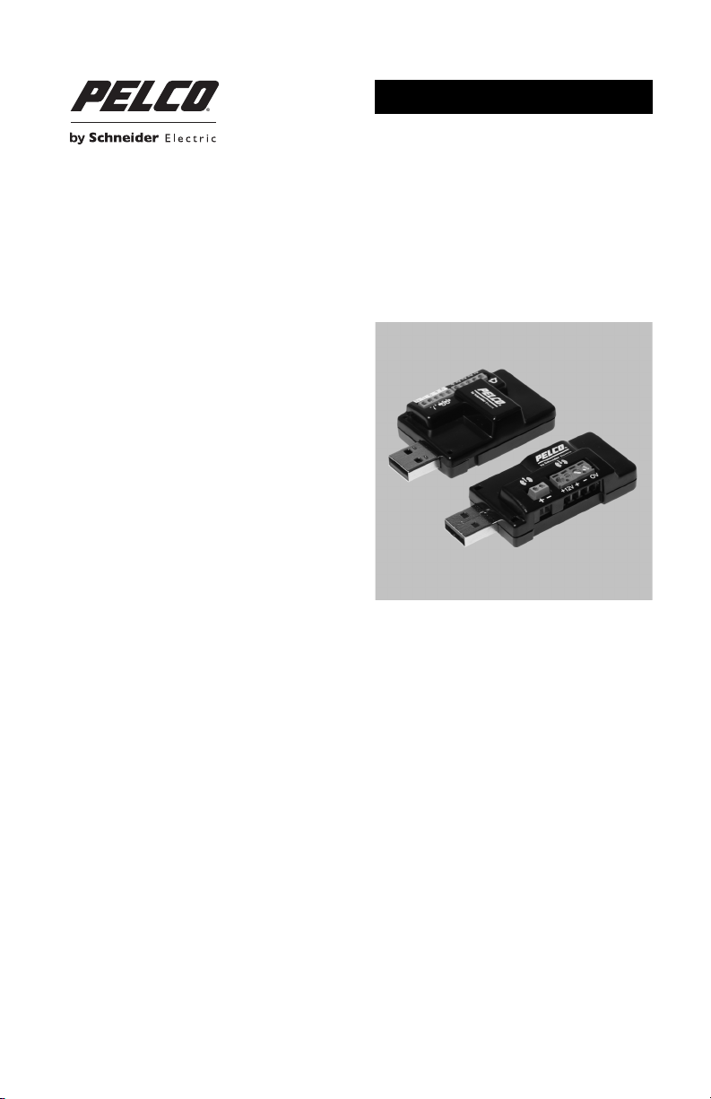
AUD-1 Audio and ALM-1 Alarm Accessories
External Audio and Alarm Accessories
C2985M-C (3/14)
Page 2

Contents
Important Notices. . . . . . . . . . . . . . . . . . . . . . . . . . . . . . . . . . . . . . . . . . . . . . . . . . . . . . . . . . . . . . . . . . . . . . 4
Legal Notice . . . . . . . . . . . . . . . . . . . . . . . . . . . . . . . . . . . . . . . . . . . . . . . . . . . . . . . . . . . . . . . . . . . . . 4
Regulatory Notices. . . . . . . . . . . . . . . . . . . . . . . . . . . . . . . . . . . . . . . . . . . . . . . . . . . . . . . . . . . . . . . . 4
Warranty Statement. . . . . . . . . . . . . . . . . . . . . . . . . . . . . . . . . . . . . . . . . . . . . . . . . . . . . . . . . . . . . . . 4
Description . . . . . . . . . . . . . . . . . . . . . . . . . . . . . . . . . . . . . . . . . . . . . . . . . . . . . . . . . . . . . . . . . . . . . . . . . . . 5
Models . . . . . . . . . . . . . . . . . . . . . . . . . . . . . . . . . . . . . . . . . . . . . . . . . . . . . . . . . . . . . . . . . . . . . . . . . 5
AUD-1 Parts List . . . . . . . . . . . . . . . . . . . . . . . . . . . . . . . . . . . . . . . . . . . . . . . . . . . . . . . . . . . . . . . . . . 5
ALM-1 Parts List. . . . . . . . . . . . . . . . . . . . . . . . . . . . . . . . . . . . . . . . . . . . . . . . . . . . . . . . . . . . . . . . . . 5
User-Supplied Parts List. . . . . . . . . . . . . . . . . . . . . . . . . . . . . . . . . . . . . . . . . . . . . . . . . . . . . . . . . . . . 5
Installation . . . . . . . . . . . . . . . . . . . . . . . . . . . . . . . . . . . . . . . . . . . . . . . . . . . . . . . . . . . . . . . . . . . . . . . . . . . 6
Wiring. . . . . . . . . . . . . . . . . . . . . . . . . . . . . . . . . . . . . . . . . . . . . . . . . . . . . . . . . . . . . . . . . . . . . . . . . . . . . . . 7
Audio . . . . . . . . . . . . . . . . . . . . . . . . . . . . . . . . . . . . . . . . . . . . . . . . . . . . . . . . . . . . . . . . . . . . . . . . . . 7
Alarm . . . . . . . . . . . . . . . . . . . . . . . . . . . . . . . . . . . . . . . . . . . . . . . . . . . . . . . . . . . . . . . . . . . . . . . . . . 8
Connecting a Relay Device. . . . . . . . . . . . . . . . . . . . . . . . . . . . . . . . . . . . . . . . . . . . . . . . . . . . . 9
Connecting Alarms . . . . . . . . . . . . . . . . . . . . . . . . . . . . . . . . . . . . . . . . . . . . . . . . . . . . . . . . . . . 9
Troubleshooting . . . . . . . . . . . . . . . . . . . . . . . . . . . . . . . . . . . . . . . . . . . . . . . . . . . . . . . . . . . . . . . . . . . . . . 12
Specifications. . . . . . . . . . . . . . . . . . . . . . . . . . . . . . . . . . . . . . . . . . . . . . . . . . . . . . . . . . . . . . . . . . . . . . . . 13
AUD-1 . . . . . . . . . . . . . . . . . . . . . . . . . . . . . . . . . . . . . . . . . . . . . . . . . . . . . . . . . . . . . . . . . . . . . . . . . 13
ALM-1. . . . . . . . . . . . . . . . . . . . . . . . . . . . . . . . . . . . . . . . . . . . . . . . . . . . . . . . . . . . . . . . . . . . . . . . . 14
C2985M-C (3/14) 2
Page 3

List of Illustrations
1 Installing the AUD-1 and ALM-1 into a Spectra HD Series Camera . . . . . . . . . . . . . . . . . . . . . . . . . . 6
2 Wiring the AUD-1. . . . . . . . . . . . . . . . . . . . . . . . . . . . . . . . . . . . . . . . . . . . . . . . . . . . . . . . . . . . . . . . . 7
3 Wiring the ALM-1. . . . . . . . . . . . . . . . . . . . . . . . . . . . . . . . . . . . . . . . . . . . . . . . . . . . . . . . . . . . . . . . . 8
4 Supervised Alarm Conditions. . . . . . . . . . . . . . . . . . . . . . . . . . . . . . . . . . . . . . . . . . . . . . . . . . . . . . . . 9
5 Supervised Alarm Input Wiring . . . . . . . . . . . . . . . . . . . . . . . . . . . . . . . . . . . . . . . . . . . . . . . . . . . . . 10
6 Unsupervised Alarm Conditions. . . . . . . . . . . . . . . . . . . . . . . . . . . . . . . . . . . . . . . . . . . . . . . . . . . . . 10
7 Normally Closed and Normally Open Unsupervised Alarm Input Wiring . . . . . . . . . . . . . . . . . . . . . 10
8 Alarm Connections . . . . . . . . . . . . . . . . . . . . . . . . . . . . . . . . . . . . . . . . . . . . . . . . . . . . . . . . . . . . . . . 11
C2985M-C (3/14) 3
Page 4

Important Notices
LEGAL NOTICE
SOME PELCO EQUIPMENT CONTAINS, AND THE SOFTWARE ENABLES, AUDIO/VISUAL AND RECORDING
CAPABILITIES, THE IMPROPER USE OF WHICH MAY SUBJECT YOU TO CIVIL AND CRIMINAL PENALTIES.
APPLICABLE LAWS REGARDING THE USE OF SUCH CAPABILITIES VARY BETWEEN JURISDICTIONS AND
MAY REQUIRE, AMONG OTHER THINGS, EXPRESS WRITTEN CONSENT FROM RECORDED SUBJECTS.
YOU ARE SOLELY RESPONSIBLE FOR ENSURING STRICT COMPLIANCE WITH SUCH LAWS AND FOR
STRICT ADHERENCE TO ANY/ALL RIGHTS OF PRIVACY AND PERSONALTY. USE OF THIS EQUIPMENT
AND/OR SOFTWARE FOR ILLEGAL SURVEILLANCE OR MONITORING SHALL BE DEEMED UNAUTHORIZED
USE IN VIOLATION OF THE END USER SOFTWARE AGREEMENT AND RESULT IN THE IMMEDIATE
TERMINATION OF YOUR LICENSE RIGHTS THEREUNDER.
REGULATORY NOTICES
This device complies with Part 15 of the FCC Rules. Operation is subject to the following two conditions:
(1) this device may not cause harmful interference, and (2) this device must accept any interference
received, including interference that may cause undesired operation.
RADIO AND TELEVISION INTERFERENCE
This equipment has been tested and found to comply with the limits of a Class A digital device, pursuant
to Part 15 of the FCC rules. These limits are designed to provide reasonable protection against harmful
interference when the equipment is operated in a commercial environment. This equipment generates,
uses, and can radiate radio frequency energy and, if not installed and used in accordance with the
instruction manual, may cause harmful interference to radio communications. Operation of this equipment
in a residential area is likely to cause harmful interference in which case the user will be required to
correct the interference at his own expense.
Changes and Modifications not expressly approved by the manufacturer or registrant of this equipment
can void your authority to operate this equipment under Federal Communications Commission’s rules.
In order to maintain compliance with FCC regulations, shielded cables must be used with this equipment.
Operation with non-approved equipment or unshielded cables is likely to result in interference to radio and
television reception.
This Class A digital apparatus complies with Canadian ICES-003.
Cet appareil numérique de la classe A est conforme à la norme NMB-003 du Canada.
WARRANTY STATEMENT
For information about Pelco’s product warranty and thereto related information, refer to www.pelco.com/
warranty.
C2985M-C (3/14) 4
Page 5

Description
The AUD-1 and ALM-1 are external accessories that can be connected directly to the accessory port of
compatible Pelco devices. The AUD-1 is compatible with Spectra
camera models that do not have built-in audio. The ALM-1 is compatible with Spectra HD Series dome
systems and most Sarix camera models.
The AUD-1 audio accessory is designed to work with microphones that have an internal preamplifier and
provide a line-level output. The AUD-1 encodes audio from the microphone into a digital G.711 format. The
audio can be streamed with the video to be played back and recorded at the headend. The AUD-1 can also
receive the G.711 digital audio from the headend and convert it to an analog signal to be played through a
speaker.
The ALM-1 alarm accessory features four alarm inputs, one auxiliary (Form C) relay output, and one open
collector auxiliary output that can be alternatively configured to operate on alarm. Up to four ALM-1 alarm
accessories can be configured for one device, which may require a USB hub. Each accessory is
automatically recognized and configured by the Pelco device.
The audio and alarm accessories can be used simultaneously; however, if the Pelco device has only one
accessory port, a USB hub is required.
NOTE: The ALM-1 accessory is not supported by DS ControlPoint.
®
HD Series dome systems and Sarix®
MODELS
AUD-1 External audio accessory
ALM-1 External alarm accessory
AUD-1 PARTS LIST
The following parts are supplied:
Qty Description
1 AUD-1 audio accessory
1 Left-angle USB cable (for use with Sarix IM Series cameras)
1 Mini USB cable (for use with Sarix IX and ID Series cameras)
ALM-1 PARTS LIST
The following parts are supplied:
Qty Description
1 ALM-1 alarm accessory
1 Left-angle USB cable (for use with Sarix IM Series cameras)
1 Mini USB cable (for use with Sarix IX and ID Series cameras)
1 Micro B USB cable (for use with Sarix Enhanced IXE and IME Series cameras)
USER-SUPPLIED PARTS LIST
The following tools are recommended:
Qty Description
1 1.4 mm or 2.0 mm screwdriver
5 C2985M-C (3/14)
Page 6

Installation
1. Locate the camera’s USB accessory port.
2. Connect the accessory appropriate for one of the following camera types:
• IE Series and Spectra HD Series: Connect the accessory directly to the camera’s USB
accessory port.
NOTE: For Spectra HD Series cameras, the ALM-1 alarm accessory must be connected to the
accessory port closest to the dome drive when installed (refer to Figure 1).
• IX Series and ID Series: Connect the mini USB cable (supplied) to the accessory, and then
connect it to the camera’s USB accessory port.
• IM Series: Connect the left-angle USB cable (supplied) to the accessory, and then connect it
to the camera’s USB accessory port.
• Enhanced IXE and IME Series: Connect the micro B USB cable (supplied) to the accessory,
and then connect it to the camera’s USB accessory port.
Figure 1. Installing the AUD-1 and ALM-1 into a Spectra HD Series Camera
ì=
Spectra HD Dome Drive Receiver (located inside the back box)
î=
USB Ports
ï
AUD-1 Audio Accessory
ñ
ALM-1 Alarm Accessory
ó=
Spectra HD Dome Drive
3. Connect the appropriate wiring (refer to Wiring on page 7).
4. Log on to the host camera, and enable the camera’s audio or alarm streams as needed. Refer to the
installation/operation manual shipped with the camera for complete instructions.
NOTE: Improper use of audio/visual recording equipment may subject you to civil and criminal penalties.
Applicable laws regarding the use of such capabilities vary between jurisdictions and may require, among
other things, express written consent from the recorded subjects. You are solely responsible for ensuring
strict compliance with such laws and for strict adherence to any/all rights of privacy and personalty.
C2985M-C (3/14) 6
Page 7

Wiring
AUDIO
NOTES:
• The maximum recommended cable length for the audio wiring is 304.8 m (1,000 ft).
• The AUD-1 is designed to work with microphones that have an internal preamplifier and provide
professional line-level output (+4 dBu).
• If your microphone requires more than 12 VDC power, you will need to use a separate power line to
power the microphone unit.
• If your microphone is a consumer line-level device (–10 dBu), the audio output may be quieter than
you expect. Mic-level devices are not recommended as they must be amplified to a line-level signal,
which often results in excessive noise.
To connect the wiring for the AUD-1:
1. Connect UTP wiring from an external microphone to pins 2 and 3 of the AUD-1 TB2 connector.
2. To supply power to the microphone, connect UTP wiring to the power terminals of the microphone
and terminate them at pins 1 (12 VDC) and 4 (return) of the AUD-1 TB2 connector.
3. Connect UTP wiring from the external speakers to pins 1 and 2 of the AUD-1 TB1 connector.
Figure 2. Wiring the AUD-1
ì
Speaker
î
Amplifier
ï
600-Ohm Impedance Matching Transformer
ñ
UTP Wiring
ó
+12 V Wire
r
0 V (zero volt) Return Wire
s
UTP Wiring
t
600-Ohm Impedance Matching Transformer
u
Line-Level Microphone
7 C2985M-C (3/14)
Page 8

ALARM
1. Connect one wire of a UTP wire pair from each of your alarm input switches to pins 1 to 4 of the
ALM-1 TB1 connector.
2. Connect the remaining wire of the UTP wire pair from your each of your alarm input switches to a
wire nut or terminal block, and then run a single wire to the return pin 5 of the ALM-1 TB1 connector.
3. Connect UTP wiring from your alarm output devices to the ALM-1 TB2 connector.
ALM1
ALM2
ALM3
ALM4
RTN
TB1
12345
TB2
Figure 3. Wiring the ALM-1
ì
Common Return
î
N.C. Wire Pair
ï
N.O. Wire Pair
ñ
Solid-State Relay Wire Pair
ó
Customer Relay Devices
r
N.O. Alarm Input Switches
s
N.C. Alarm Input Switches
C2985M-C (3/14) 8
Page 9

CONNECTING A RELAY DEVICE
The ALM-1 has four outputs for activating external devices. It supports both momentary and continuous
relay operation.
You can operate the relays interactively during an active connection, or they can operate automatically to
coincide with certain events. Typical applications include turning on lights or other electrical devices or
activating a door, gate, or lock.
WARNING: Do not exceed the maximum relay ratings of 40 V, 2 A, or 60 W.
CONNECTING ALARMS
The ALM-1 provides four alarm inputs for external signaling devices, such as door contacts or motion
detectors. Both normally open and normally closed devices are supported.
Supervised Alarms
When an alarm is configured as a supervised alarm, the ALM-1 maintains a constant electrical current
through the alarm circuit (3.3 VDC, 1 kohm). If the alarm circuit length changes, due to an electrical short
or a bypass, the voltage fluctuates from its normal state and activates an alarm.
NOTE: Install the 1-kohm resistor as close to the switch as possible.
Figure 4 illustrates the alarm and no alarm conditions of a supervised alarm input. Whether the alarm is
normally closed or normally open, neither a cut nor a bypass can defeat these alarms.
NORMALLY OPENNORMALLY CLOSED
NO ALARM
GND
1 KΩ
+V
NO ALARM
GND
1 KΩ
+V
ALARM
GND
ALARM
GND
ALARM
GND
1 KΩ
+V
1 KΩ
+V
CUT
1 KΩ
+V
BYPASS
ALARM
GND
ALARM
GND
ALARM
GND
1 KΩ
+V
1 KΩ
+V
CUT
1 KΩ
+V
BYPASS
Figure 4. Supervised Alarm Conditions
9 C2985M-C (3/14)
Page 10

Figure 5 illustrates the wiring configuration for supervised alarm inputs.
1 KΩ
A
1
1 KΩ
A
1
NORMALLY OPENNORMALLY CLOSED
+V
+V
+V
+V
+V
+V
+V
+V
BYPASS
CUT
BYPASS
CUT
GND
ALARM
GND
ALARM
GND
NO ALARM
GND
NO ALARM
GND
NO ALARM
GND
ALARM
GND
NO ALARM
GND
ALARM
NORMALLY OPENNORMALLY CLOSED
A1A1
NORMALLY OPENNORMALLY CLOSED
Figure 5. Supervised Alarm Input Wiring
Unsupervised Alarms
When an alarm is configured as an unsupervised alarm, an alarm is only activated when the normal alarm
state (open or closed) changes.
Figure 6 illustrates the alarm and no alarm conditions of an unsupervised alarm input.
Figure 6. Unsupervised Alarm Conditions
Figure 7 illustrates the wiring configuration for unsupervised alarm inputs.
Figure 7. Normally Closed and Normally Open Unsupervised Alarm Input Wiring
NOTE: A normally closed alarm input can be defeated with a bypass; a normally open input can be
defeated with a cut.
C2985M-C (3/14) 10
Page 11

Alarm Connections
Figure 8 shows how to wire the ALM-1 to an alarm.
ALARM A1
ALARM
Figure 8. Alarm Connections
11 C2985M-C (3/14)
Page 12

Troubleshooting
If the following instructions fail to solve your problem, contact Pelco Product Support at 1-800-289-9100
(USA and Canada) or +1-559-292-1981 (international) for assistance. Be sure to have the serial number
available when calling.
Do not try to repair the unit yourself. Leave maintenance and repairs to qualified technical personnel only.
Table A. Troubleshooting the AUD-1 and the ALM-1
Problem Possible Cause Suggested Solution
Cannot enable the
accessory.
The AUD-1 does not
respond.
The audio signal is
weak.
The audio signal is noisy. You are using a mic-level
The accessory is not
correctly installed.
The accessory is not
enabled.
The accessory settings
were not saved.
There is a problem with
the wiring.
The sampling rate is set
incorrectly.
The microphone you are
using is not a line-level
device.
There is no power to the
microphone.
There is no speaker
amplification.
You are not using the
correct type of
transformer.
The wiring distance
between the audio
equipment may be too
long.
The gain is not properly
adjusted.
You are using a
consumer line-level
microphone.
microphone rather than
a line-level microphone.
Ensure that the accessory is installed
completely and correctly.
Enable the accessory.
Save the settings after configuring the
accessory.
Ensure that the wiring is properly installed.
Set the sampling rate to 8 kHz.
Use a line-level microphone.
Apply power to the microphone (refer to
Wiring on page 7).
Ensure that the line out wiring includes an
amplifier.
Use a 600-ohm impedance matching
transformer.
Test the equipment using a shorter wiring
distance.
If you are using an external amplifier and it
has an adjustable gain, increase the gain
until the signal is acceptable.
Use a professional line-level microphone.
Add an external amplifier to your circuit and
or adjust the gain.
Use a line-level microphone.
Add an external amplifier that will bring the
signal to line level.
C2985M-C (3/14) 12
Page 13

Specifications
AUD-1
GENERAL
Compression G.711
Sampling Rate 8 kHz
Bit Rate 64 kbps (8 kHz)
Dimensions 62.2 x 29.2 x 16.0 mm
Weight 0.02 kg (0.04 lb)
ELECTRICAL
Power Input 5 VDC powered from USB
MECHANICAL
Audio Input UTP 600 ohms mono using 4X terminal block (screw connection)
Audio Output UTP 600 ohms mono using 2X terminal block (screw connection)
Connector USB 2.0 ’A’ male
ENVIRONMENTAL
Operating Temperature 0° to 60°C (32° to 140°F)
Storage Temperature –20° to 60°C (–4° to 140°F)
(2.45" L x 1.15" W x 0.63" H)
with balanced line input and 12 VCD power source
with balanced line output
13 C2985M-C (3/14)
Page 14

ALM-1
GENERAL
Dimensions 59.2 x 31.8 x 17.2 mm
Weight 0.02 kg (0.04 lb)
ELECTRICAL
Power Input 5 VDC powered from USB
Power Requirement 100 mW (17 mA, 5 V)
Mechanical Relay Limits
Switching Load 60 W maximum continuous power dissipation
Maximum Current 2 A
Maximum Voltage <40 V
Solid State Relay Limits
Maximum Continuous Current 150 mA
Maximum Voltage 32 VDC
MECHANICAL
Alarm Input Cat5 cable or 26 gauge wire
Auxiliary Input/Output Cat5 cable or 26 gauge wire
Connector USB 2.0 ’A’ male
ENVIRONMENTAL
Operating Temperature 0° to 60°C (32° to 140°F)
Storage Temperature –20° to 60°C (–4° to 140°F)
(2.33" L x 1.25" W x 0.68" H)
C2985M-C (3/14) 14
Page 15

This equipment contains electrical or electronic components that must be recycled properly to comply with Directive
2002/96/EC of the European Union regarding the disposal of waste electrical and electronic equipment (WEEE).
Contact your local dealer for procedures for recycling this equipment.
REVISION HISTORY
Manual # Date Comments
C2985M 2/11 Original version.
C2985M-A 3/11 Revised the ALM-1 accessory note in Description.
C2985M-B 9/13 Revised the ALM-1 parts list in Description. Updated warranty information.
C2985M-C 3/14 Clarified Parts List for AUD-1 and ALM-1 accessories.
Pelco, the Pelco logo, Sarix, Spectra, and other trademarks associated with Pelco products referred to in this publication are trademarks of Pelco, Inc.
or its affiliates.
All other product names and services are th e property of their respective companies. ONVIF and the ONVIF logo are trademarks of ONVIF Inc.
Product specifications and availability are subject to change without notice. © Copyright 2014, Pelco, Inc. Al l rights reserved.
Added Enhanced IXE and IME to Installation.
Page 16

Pelco by Schneider Electric 3500 Pelco Way Clovis, California 93612-5699 United States
USA & Canada Tel (800) 289-9100 Fax (800) 289-9150
International Tel +1 (559) 292-1981 Fax +1 (559) 348-1120
www.pelco.com www.pelco.com/community
 Loading...