

Peimar PSI-J3000-TL, PSI-J3000-TLM, PSI-J4000-TLM, PSI-J5000-TLM, PSI-J6000-TLM User Manual
...
MIRUS LINE - UNICUS LINE - GEMINUS LINE
IT EN ES
Manuale dell’Utente
Inverter Monofase.......3
User Manual
Single Phase Inverters.....55
Manual de Usuario
Inversor Monofásico...107
www.peimar.com


IT
Grazie per aver scelto un inverter Peimar. Siamo lieti di fornirvi prodotti di prima
categoria e un servizio esclusivo.
Questo manuale fornisce informazioni riguardanti l’installazione, il
funzionamento e la manutenzione del prodotto da voi acquistato, nonché le
indispensabili linee guida relative alla sicurezza e le istruzioni per la risoluzione
di eventuali problemi. Si prega di leggere attentamente il presente documento
e di seguirne le indicazioni, in modo tale da consentirci di fornirvi la nostra
consulenza professionale e un completo servizio d’assistenza.
Il nostro impegno è costantemente rivolto al cliente e alla sua soddisfazione.
Condiamo che questo documento possa essere un valido supporto nel
percorso da voi intrapreso verso un mondo più pulito ed ecologico.
Si prega di vericare la versione più recente del presente manuale sul sito
www.peimar.com.
Si precisa che i dati tecnici, le informazioni e le raffigurazioni riportate nel presente documento mantengono un valore puramente
indicativo. Peimar si riserva in qualsiasi momento e senza preavviso di modicare i dati, i disegni e le informazioni riportate nel
presente documento.
3

Indice
Capitolo 1
Misure di sicurezza ..............................................................................6
1.1 Campo d’applicazione ............................................................6
1.2 Istruzioni di sicurezza .............................................................6
1.3 Persone interessate ................................................................6
Capitolo 2
Preparazione .........................................................................................7
2.1 Istruzioni di sicurezza ............................................................. 7
2.2 Spiegazione dei simboli .........................................................8
Capitolo 3
Informazioni sul prodotto .................................................................. 10
3.1 Campo d’applicazione dei prodotti ....................................... 10
3.2 Specica per il modello di prodotto ...................................... 11
3.3 Prospetto e dimensioni dei prodotti ...................................... 11
3.4 Scheda tecnica - MIRUS LINE ............................................. 12
3.5 Scheda tecnica - UNICUS LINE ...........................................14
3.6 Scheda tecnica - GEMINUS LINE ........................................16
IT
Capitolo 4
Istruzioni per l’installazione .............................................................. 18
4.1 Istruzioni di sicurezza ........................................................... 18
4.2 Controllo prima dell’installazione ..........................................18
4.3 Individuazione metodo e posizione di installazione.................19
4.4 Procedura di montaggio .......................................................20
Capitolo 5
Connessione elettrica ........................................................................25
5.1 Istruzioni di sicurezza per lavori sulla linea diretta ............... 25
5.2 Precisazioni per l’interfaccia elettrica....................................26
5.3 Connessione dal lato CA ...................................................... 27
4

5.4 Connessione dal lato CC .....................................................28
5.5 Connessione di trasmissione ...............................................31
Capitolo 6
Istruzioni per il debugging.................................................................32
6.1 Presentazione dell’interfaccia uomo-macchina ....................32
6.2 Congurazione al primo avvio .............................................. 33
6.3 Display dell’inverter .............................................................. 36
6.4 Impostare i parametri generali dell’inverter .......................... 38
6.5 Auto test completo dell’inverter .............................................42
6.6 Auto test singoli dell’inverter ................................................. 43
6.7 Operazione di Monitoraggio .................................................47
Capitolo 7
Codici di errore e risoluzione dei problemi ..................................... 48
7.1 Codice errore e descrizione .................................................. 48
7.2 Indicazione errore e risoluzione del problema ......................49
IT
Capitolo 8
Riciclaggio e Smaltimento .................................................................52
Capitolo 9
Servizio di Garanzia ...........................................................................52
5

IT
Capitolo 1 - Misure di sicurezza
1.1 Campo d’applicazione
Questo manuale d’uso denisce istruzioni e procedure dettagliate per
l’installazione, il funzionamento, la manutenzione e la risoluzione dei problemi
dei seguenti inverter Peimar connessi alla rete elettrica:
PSI-J1000-TL PSI-J1500-TL PSI-J2000-TL PSI-J2500-TL PSI-J3000-TL
PSI-J3000-TLM PSI-J4000-TLM PSI-J5000-TLM PSI-J6000-TLM
Si prega di tenere sempre a disposizione questo manuale in caso d’emergenza.
1.2 Istruzioni di sicurezza
PERICOLO indica una situazione pericolosa che, se
non evitata, porterà a morte o infortuni gravi.
AVVERTENZA indica una situazione pericolosa che,
se non evitata, può portare a morte o infortuni gravi o
infortuni moderati.
ATTENZIONE indica una condizione pericolosa che,
se non evitata, può portare a infortuni minori o moderati.
AVVISO indica una situazione che può portare a danni
potenziali, se non evitata.
1.3 Personale interessato
L’installazione, la manutenzione e la riparazione dell’inverter possono essere
effettuate unicamente da personale qualicato, che abbia letto e compreso
pienamente tutti i regolamenti di sicurezza contenuti in questo manuale.
Gli operatori devono essere al corrente del fatto che l’inverter è un dispositivo
ad alta tensione.
6

Capitolo 2 - Preparazione
2.1 Istruzioni di sicurezza
PERICOLO
• C’è possibilità di morte per scosse elettriche e alta tensione.
• Non toccare le parti in tensione dell’inverter; potrebbe portare
a bruciature o morte.
• Per prevenire il rischio di scosse elettriche durante
l’installazione e la manutenzione, si prega di accertarsi che
tutti i terminali CA e CC siano scollegati.
• Non toccare la supercie dell’inverter mentre il rivestimento è
bagnato; potrebbe provocare scosse elettriche.
• Non restare vicino all’inverter durante condizioni climatiche
avverse tra cui tempeste, fulmini, ecc.
• Prima di aprire il rivestimento, l’inverter Peimar deve essere
disconnesso dalla rete e dal generatore fotovoltaico; è
necessario attendere almeno cinque minuti per permettere
ai condensatori di accumulo energetico di scaricarsi
completamente dopo essersi disconnessi dalla fonte di energia.
IT
AVVERTENZA
• L’installazione, manutenzione, riciclaggio e smaltimento
degli inverter devono essere svolti solamente da personale
qualicato in conformità con le norme e i regolamenti nazionali
e locali.
• Qualsiasi azione non autorizzata, tra cui la modica di
qualsiasi tipo di funzionalità del prodotto, può comportare un
pericolo letale per l’operatore, per terzi, per i componenti o le
loro caratteristiche. In tali casi Peimar non è responsabile per
perdita e per reclami in garanzia.
• L’inverter Peimar deve essere utilizzato esclusivamente in
combinazione con pannelli fotovoltaici. Non connettere altre
fonti di energia all’inverter Peimar.
• Assicurarsi che il generatore fotovoltaico e l’inverter siano
correttamente collegati all’impianto di terra come da normativa
vigente, per la sicurezza di persone, animali e cose.
7

ATTENZIONE
• L’inverter fotovoltaico può raggiungere elevate temperature
durante il funzionamento. Si prega di non toccare il dissipatore
di calore o la supercie laterale durante il funzionamento o
subito dopo lo spegnimento.
• Rischio di danni dovuti a modiche improprie.
AVVISO
• L’inverter fotovoltaico è progettato per immettere energia in
corrente alternata direttamente nella rete elettrica pubblica;
non connettere l’uscita CA dell’inverter ad alcun dispositivo
che non sia collegato alla rete elettrica di distribuzione
pubblica.
2.2 Spiegazione dei simboli
TENSIONE ELETTRICA PERICOLOSA
Questo dispositivo è direttamente connesso alla rete elettrica
pubblica, pertanto qualsiasi lavoro sull’inverter deve essere
svolto da personale qualicato.
IT
PERICOLO di morte dovuto ad alta tensione elettrica!
Nell’inverter si può avere una tensione residua dovuta
all’elevata capacità dei condensatori. Attendere 5 MINUTI
dopo la disconnessione dell’apparecchio prima di rimuovere
il coperchio.
AVVISO, pericolo!
L’apparecchio è direttamente connesso a generatori elettrici
e alla rete elettrica pubblica.
8

IT
PERICOLO parti calde
Gli elementi all’interno dell’inverter raggiungono elevate
temperature durante il funzionamento. Non toccare la custodia
metallica quando l’inverter è attivo (rischio di ustione).
SI È VERIFICATO UN ERRORE
Si rimanda al Capitolo 7 “Codici di Errore e Risoluzione dei
Problemi” per l’elenco completo dei codici errore e relativa
risoluzione.
Questo dispositivo NON DEVE essere smaltito come riuto
urbano. Si rimanda al Capitolo 8 “Riciclaggio e Smaltimento”
per un’adeguata gestione di smaltimento dell’inverter.
ROHS
Restriction of Hazardous Substances Directive
SENZA TRASFORMATORE
Questo inverter è privo di trasformatore di isolamento.
MESSA A TERRA
Punto di connessione del conduttore di protezione per la
messa a terra.
Marchio CE
I dispositivi con il marchio CE rispettano i requisiti
fondamentali della Direttiva Bassa Tensione e della Direttiva
Compatibilità Elettromagnetica.
9
IT
Capitolo 3 - Informazioni sul prodotto
3.1 Campo di impiego
I prodotti delle serie Mirus, Unicus e Geminus sono inverter monofase
senza trasformatore, da connettere alla rete elettrica. Essi sono componenti
fondamentali negli impianti fotovoltaici connessi in rete.
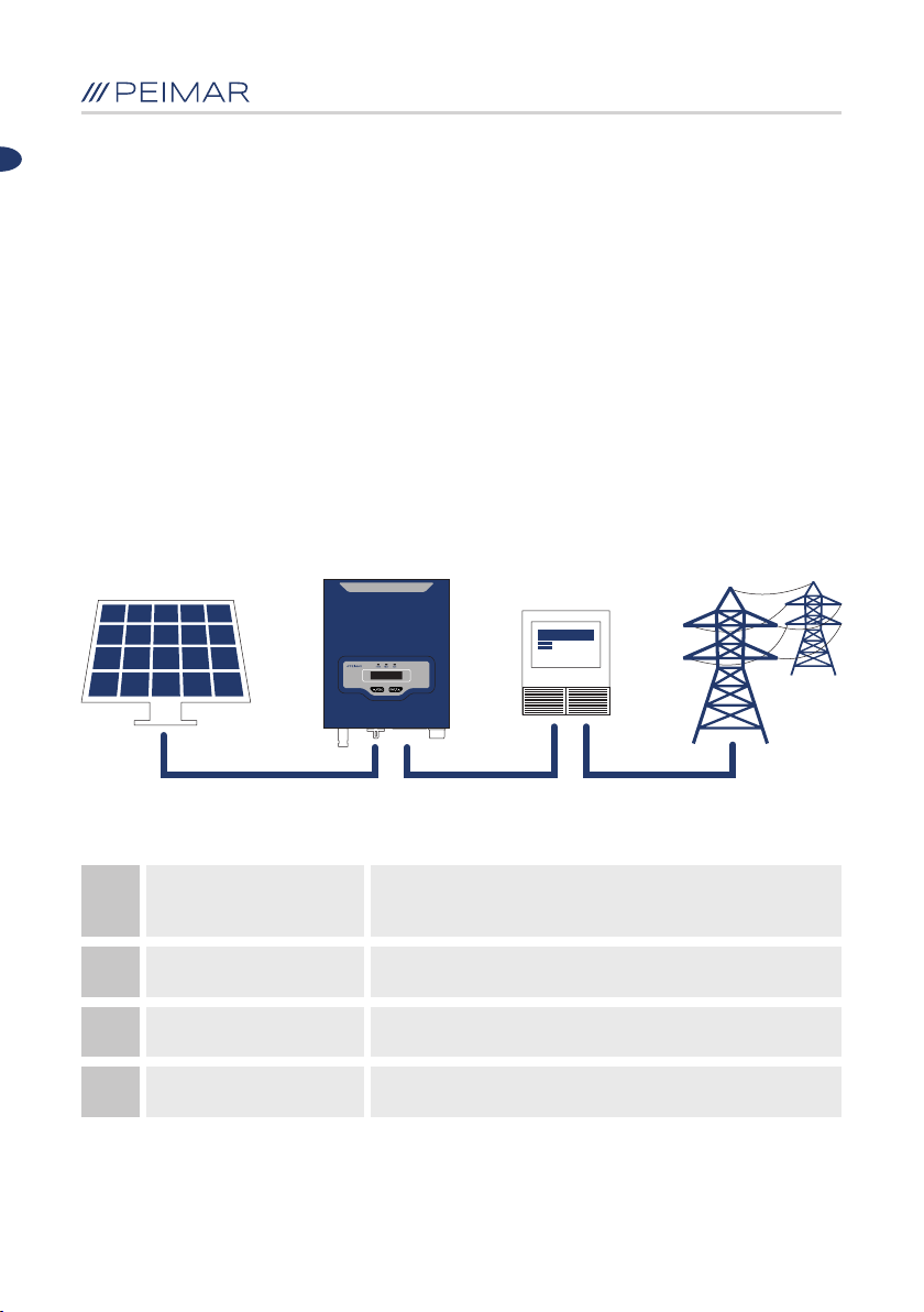
Gli inverter Mirus, Unicus e Geminus ricevono l’energia elettrica generata in
corrente continua (CC) dai pannelli solari e la convertono in corrente alternata
(CA) conformemente ai requisiti della rete pubblica, per poter essere dunque
utilizzata per l’alimentazione delle utenze elettriche dell’abitazione o della
propria attività, e per poter immettere in rete il surplus. La Tabella 3.1 mostra lo
schema strutturale del tipico sistema di applicazione degli inverter.
A B C D
Moduli fotovoltaici in silicio monocristallino o policristallino,
A
B
C
D
Pannelli solari
Inverter
Apparecchio di
misura (contatore)
Rete elettrica
e a lm sottile con protezione di livello II e senza bisogno
di collegamento a terra
Mirus, Unicus e Geminus
Strumento di misura standard (contatore) per conteggiare
l’energia elettrica prodotta dall’inverter
Tipologie di rete elettrica: TT, TN-C, TN-S, TN-C-S
Tabella 3.1 Schema di congurazione
10

3.2 Specicazione del modello di prodotto
PSI-JXXXX-TL PSI-JXXXX-TLM
• PSI-J indica il nome del prodotto
• XXXX indica la potenza nominale in W dell’inverter
• TL indica che si tratta di un inverter senza trasformatore (transformerless)
• M indica la funzionalità di doppio MPPT dell’inverter
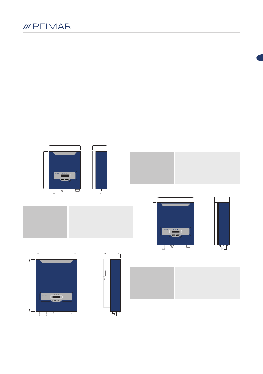
3.3 Panoramica e dimensioni dei prodotti
Le dimensioni dei prodotti sono indicate nella Figura 3.2.
260 mm 120 mm
IT
315 mm
SERIE
UNICUS
355 mm 150/162 mm
454
SERIE
MIRUS
305 mm 120
PSI-J2000-TL
PSI-J2500-TL
PSI-J3000-TL
354 mm
SERIE
GEMINUS
Figura 3.2 Dimensioni dei prodotti Mirus, Unicus e Geminus
PSI-J1000-TL
PSI-J1500-TL
PSI-J3000-TLM
PSI-J4000-TLM
PSI-J5000-TLM
PSI-J6000-TLM
11

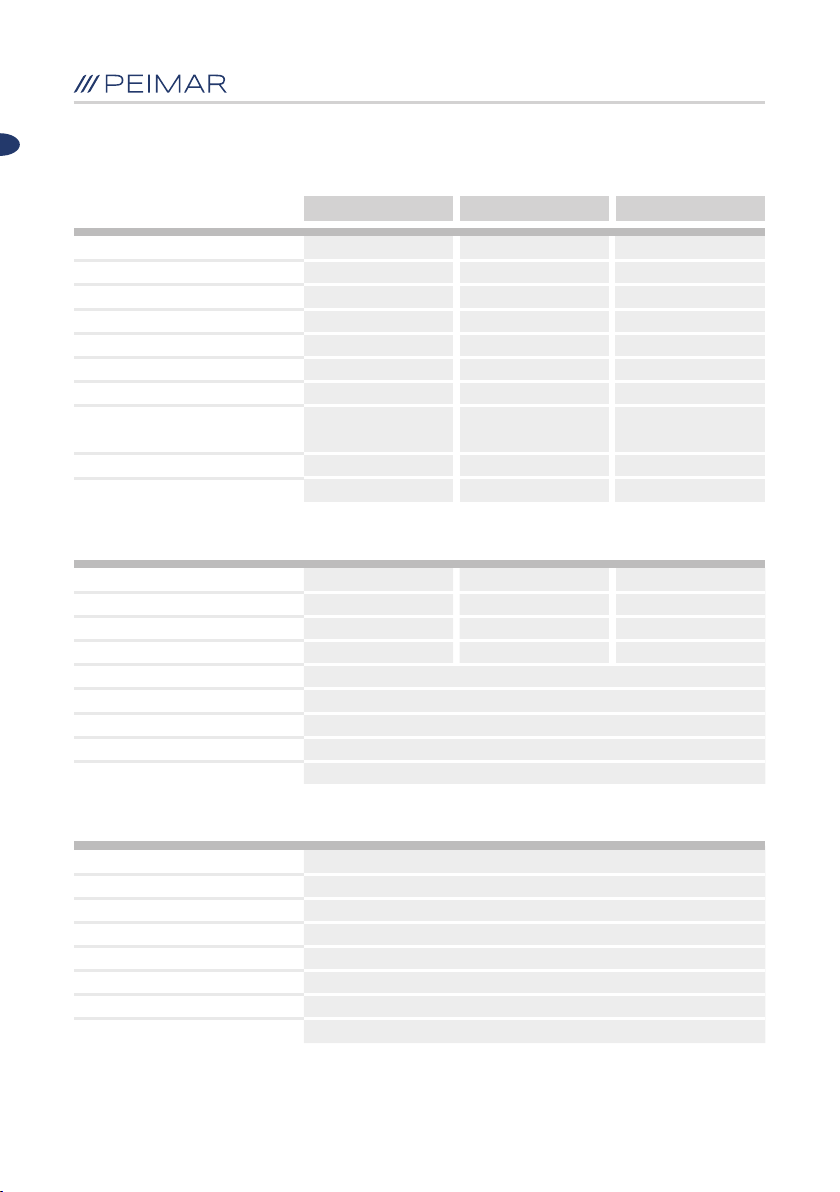
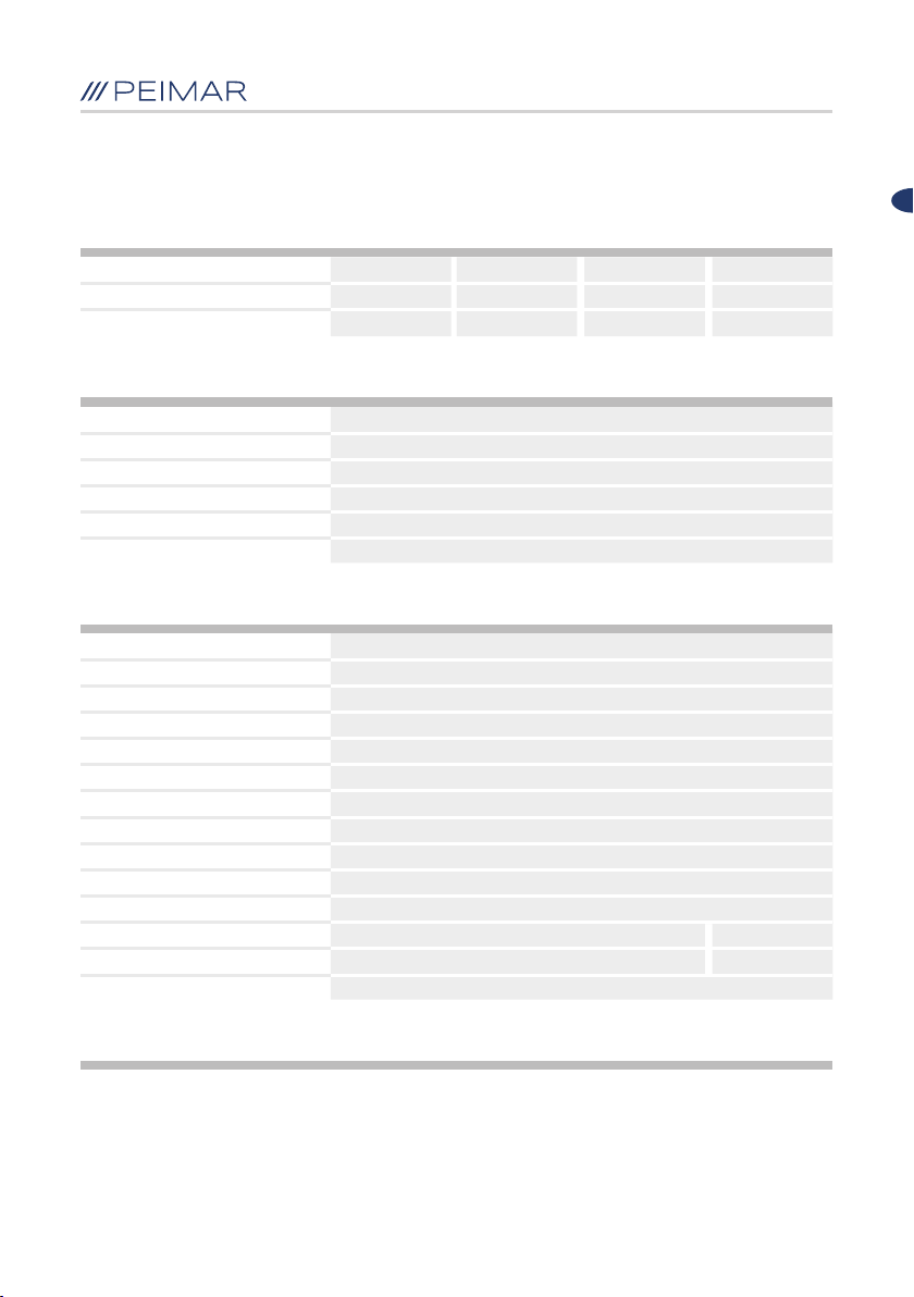
3.4 Scheda tecnica - MIRUS LINE
IT
Ingresso CC
Potenza massima CC
Tensione massima CC
Range di tensione MPPT
Tensione nominale CC
Tensione di avvio
Tensione minima CC
Corrente di ingresso massima CC
Numero di ingressi CC per ogni
MPPT
Numero di MPPT
Sezionatore CC (DC21B)
Uscita CA
Potenza nominale CA
Potenza massima CA
Corrente nominale CA
Corrente massima CA
Tensione nominale CA / Range
Frequenza di rete / Range
Fattore di potenza [cos φ]
Distorsione armonica totale
Connessione
PSI-J1000-TL PSI-J1500-TL
1200 W
450 V
60-425 V
360 V
70 V
50 V
11 A
1 1
1
Integrato
1000 W
1100 W
4.3 A
5.3 A
220 V, 230 V, 240 V / 180 V - 280 V
50 Hz, 60 Hz / ±5 Hz
> 0.99 (a pieno carico)
< 3%
Monofase 1L + N + PE
1800 W
450 V
60-425 V
360 V
70 V
50 V
11 A
1
Integrato
1500 W
1650 W
6.5 A
7.9 A
Protezione
Protezione sovratesione interna
Monitoraggio isolamento CC
Monitoraggio DCI
Monitoraggio GFCI
Monitoraggio della rete elettrica
Prot. da corrente di cortocircuito CA
Protezione termica
Protezione anti-isola
Integrata
Integrato
Integrato
Integrato
Integrato
Integrata
Integrata
AFD
12

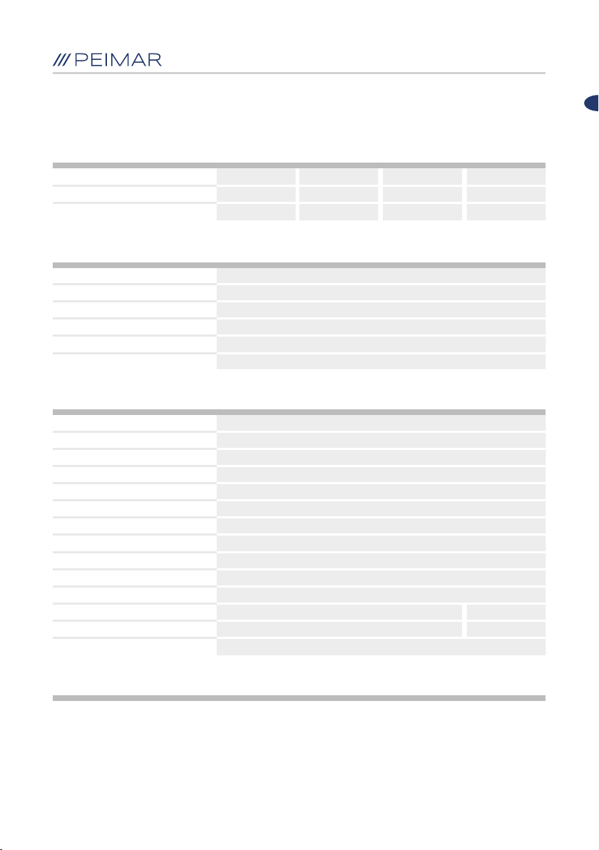
Rendimento
Rendimento massimo
Rendimento europeo
Precisione MPPT
Interfaccia
Connessione CA
Connessione CC
LCD
LED
Lingua di visualizzazione
Datalogger e comunicazione
Informazioni Generali
Topologia
Consumo notturno
Consumo in Standby
Range di temp. in funzionamento
Metodo di raffreddamento
Umidità ambientale
Altitudine
Rumore
Categoria di Sovratensione
Grado di protezione
Montaggio
Dimensioni (H x L x P) [mm]
Peso netto
Garanzia [Anno]
97.1%
96.6%
> 99.5%
Connettore a spina
MC4 / H4
LCD (caratteri 16 x 2, retroilluminazione)
LED (3 luci)
Italiano / Inglese / Spagnolo
RS-232 / Wi-Fi (opzionale)
Senza trasformatore
< 0.2 W
6 W
Da -25 °C a + 60 °C (45 °C a 60 °C con derating)
Convezione naturale
Da 0% a 100% senza condensa
Fino a 2000 m (senza derating)
< 15 dBA
II (ingresso CC) III (uscita CA)
IP65 (Installazione interna ed esterna)
Staffa di ssaggio a parete
315 x 260 x 120
5.6 kg
5 (standard) / 10 (opzionale)
97.2%
96.7%
> 99.5%
IT
Certicati
Per un elenco completo dei certicati fare riferimento al sito www.peimar.com
13
3.5 Scheda tecnica - UNICUS LINE
IT
Ingresso CC
Potenza massima CC
Tensione massima CC
Range di tensione MPPT
Tensione nominale CC
Tensione di avvio
Tensione minima CC
Corrente di ingresso massima CC
Numero di ingressi CC per ogni
MPPT
Numero di MPPT
Sezionatore CC (DC21B)
Uscita CA
Potenza nominale CA
Potenza massima CA
Corrente nominale CA
Corrente massima CA
Tensione nominale CA / Range
Frequenza di rete / Range
Fattore di potenza [cos φ]
Distorsione armonica totale
Connessione
PSI-J2000-TL PSI-J2500-TL PSI-J3000-TL
2400 W
500 V
60-450 V
360 V
70 V
50 V
11 A
1 1 1
1
Integrato
2000 W
2200 W
8.7 A
10.6 A
220 V, 230 V, 240 V / 180 V - 280 V
3000 W
500 V
60-450 V
360 V
70 V
50 V
11 A
1
Integrato
2500 W
2750 W
10.9 A
13.3 A
50 Hz, 60 Hz / ±5 Hz
> 0.99 (a pieno carico)
< 3%
Monofase 1L + N + PE
3630 W
550 V
60-500 V
360 V
70 V
50 V
11 A
1
Integrato
3000 W
3300 W
13.0 A
15.9 A
Protezione
Protezione sovratesione interna
Monitoraggio isolamento CC
Monitoraggio DCI
Monitoraggio GFCI
Monitoraggio della rete elettrica
Prot. da corrente di cortocircuito CA
Protezione termica
Protezione anti-isola
Integrata
Integrato
Integrato
Integrato
Integrato
Integrata
Integrata
AFD
14

Rendimento
Rendimento massimo
Rendimento europeo
Precisione MPPT
Interfaccia
Connessione CA
Connessione CC
LCD
LED
Lingua di visualizzazione
Datalogger e comunicazione
Informazioni Generali
Topologia
Consumo notturno
Consumo in Standby
Range di temp. in funzionamento
Metodo di raffreddamento
Umidità ambientale
Altitudine
Rumore
Categoria di Sovratensione
Grado di protezione
Montaggio
Dimensioni (H x L x P) [mm]
Peso netto
Garanzia [Anno]
97.4%
96.9%
> 99.5%
LCD (caratteri 16 x 2, retroilluminazione)
Italiano / Inglese / Spagnolo
Da -25 °C a + 60 °C (45 °C a 60 °C con derating)
Da 0% a 100% senza condensa
Fino a 2000 m (senza derating)
II (ingresso CC) III (uscita CA)
IP65 (Installazione interna ed esterna)
Staffa di ssaggio a parete
5 (standard) / 10 (opzionale)
97.5%
97.0%
> 99.5%
Connettore a spina
MC4 / H4
LED (3 luci)
RS-232 / Wi-Fi
Senza trasformatore
< 0.2 W
6 W
Convezione naturale
< 15 dBA
354 x 305 x 120
IT
97.6%
97.1%
> 99.5%
8.4 kg8.3 kg7.8 kg
Certicati
Per un elenco completo dei certicati fare riferimento al sito www.peimar.com
15

3.6 Scheda tecnica - GEMINUS LINE
IT
Ingresso CC
Potenza massima CC
Tensione massima CC
Range di tensione MPPT
Tensione nominale CC
Tensione di avvio
Tensione minima CC
Corrente di ingresso massima CC
Numero di ingressi CC per ogni
MPPT
Numero di MPPT
Sezionatore CC (DC21B)
Uscita CA
Potenza nominale CA
Potenza massima CA
Corrente nominale CA
Corrente massima CA
Tensione nominale CA / Range
Frequenza di rete / Range
Fattore di potenza [cos φ]
Distorsione armonica totale
Connessione
PSI-J6000-TLMPSI-J5000-TLMPSI-J4000-TLMPSI-J3000-TLM
3630 W
600 V
90-550 V
360 V
100 V
80 V
11 / 11 A
1 / 1 1 / 1 1 / 1 1 / 1
2
Integrato
3000 W
3300 W
13.0 A
15.9 A
4840 W
600 V
90-550 V
360 V
100 V
80 V
11 / 11 A
2
Integrato
1
3680
/ 4000 W
3680 / 4400 W
16.0 / 17.4 A
16.0 / 21.0 A
220 V, 230 V, 240 V / 180 V - 280 V
50 Hz, 60 Hz / ±5 Hz
0.8 capacitiva ~ 0.8 induttiva
Monofase 1L + N + PE
6050 W
600 V
90-550 V
360 V
100 V
80 V
11 / 11 A
2
Integrato
46002 / 5000 W
4600 / 5500 W
20.0 / 21.7 A
22.2 / 26.7 A
< 3%
7200 W
600 V
90-550 V
360 V
100 V
80 V
11 / 11 A
2
Integrato
6000 W
6000 W
26.1 A
28.7 A
Protezione
Protezione sovratesione interna
Monitoraggio isolamento CC
Monitoraggio DCI
Monitoraggio GFCI
Monitoraggio della rete elettrica
Prot. da corrente di cortocircuito CA
Protezione termica
Protezione anti-isola
Integrata
Integrato
Integrato
Integrato
Integrato
Integrata
Integrata
AFD
16
Rendimento
Rendimento massimo
Rendimento europeo
Precisione MPPT
Interfaccia
Connessione CA
Connessione CC
LCD
LED
Lingua di visualizzazione
Datalogger e comunicazione
Informazioni Generali
Topologia
Consumo notturno
Consumo in Standby
Range di temp. in funzionamento
Metodo di raffreddamento
Umidità ambientale
Altitudine
Rumore
Categoria di Sovratensione
Grado di protezione
Montaggio
Dimensioni (H x L x P) [mm]
Peso netto
Garanzia [Anno]
97.6%
97.1%
> 99.5%
Da -25 °C a + 60 °C (45 °C a 60 °C con derating)
97.8%
97.4%
> 99.5%
Connettore a spina
MC4 / H4
LCD (caratteri 16 x 2, retroilluminazione)
LED (3 luci)
Italiano / Inglese / Spagnolo
RS-232 / Wi-Fi
Senza trasformatore
Convezione naturale
Da 0% a 98% senza condensa
Fino a 2000 m (senza derating)
< 25 dBA
II (ingresso CC) III (uscita CA)
IP65 (Installazione interna ed esterna)
Staffa di ssaggio a parete
454 x 355 x 150
14.8 kg
5 (standard) / 10 (opzionale)
> 99.5%
< 0.2 W
6 W
97.9%
97.5%
IT
97.9%
97.5%
> 99.5%
454 x 355 x 162
15.8 kg
Certicati
Per un elenco completo dei certicati fare riferimento al sito www.peimar.com
1. Soddisfa lo standard di rete secondo cui la massima corrente non supera i 16A per fase
2. Soddisfa il VDE - ARN - N 4105 secondo cui la massima potenza apparente non supera i 4600 VA per fase
17
Capitolo 4 - Istruzioni per l’installazione
4.1 Istruzioni di sicurezza
PERICOLO
• Pericolo per la vita dovuto a rischio di incendio o scosse
elettriche.
• Non installare l’inverter vicino a oggetti inammabili o
esplosivi.
• Questo inverter sarà direttamente connesso ad un
generatore elettrico ad ALTA TENSIONE; l’installazione deve
essere effettuata esclusivamente da personale qualicato in
conformità alle norme e regolamenti nazionali e locali.
AVVISO
• Questo dispositivo è compatibile al grado II di inquinamento
ambientale per ambiente esterno.
• Un ambiente di installazione inappropriato o non conforme
può compromettere la durata dell’inverter.
• Si sconsiglia l’installazione dell’inverter con esposizione
diretta ai raggi solari.
• Il luogo di installazione deve essere ben ventilato.
IT
4.2 Controllo prima dell’installazione
4.2.1 Controllare l’imballaggio
Sebbene gli inverter Peimar abbiano superato collaudi rigorosi e vengano
controllati prima che lascino la fabbrica, non è escluso che possano subire dei
danni durante il trasporto.
Si prega di vericare se l’imballaggio abbia riportato evidenti segni di
danneggiamento e, nel caso in cui si verichi tale evidenza, si prega di non
aprire la scatola e contattare quanto prima il proprio rivenditore.
4.2.2 Controllare i pezzi di montaggio
Si prega di fare riferimento all’elenco componenti contenuto nell’imballaggio.
18
IT
4.3 Individuazione modalità e posizione di installazione
4.3.1 Modalità di montaggio
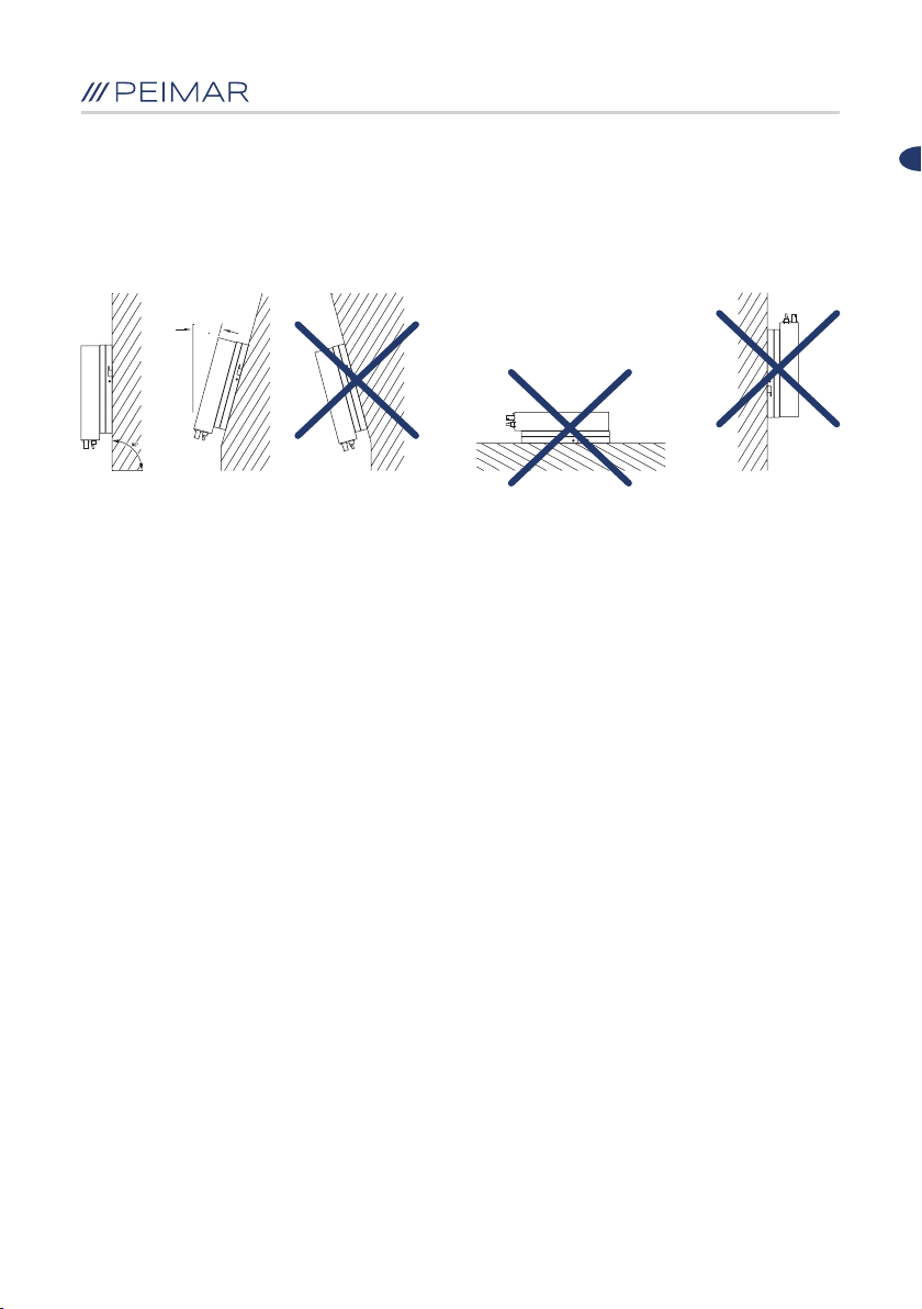
Si prega di montare l’inverter correttamente come mostrato nella Figura 4.1.
MAX 15°
Figura 4.1 Modalità di montaggio
1. Il dispositivo viene raffreddato mediante convezione naturale e può essere
installato in ambienti interni o esterni.
2. Si prega di installare il dispositivo come raffigurato nella Figura 4.1. Si
consiglia l’installazione verticale, o con un’inclinazione massima di 15°
all’indietro. Non installare mai l’inverter con inclinazione in avanti, di lato,
orizzontale o in posizione capovolta.
3. Installare l’inverter ad altezza uomo per facilitare la visualizzazione del
display e le possibili attività di manutenzione.
4. Effettuare l’installazione dell’inverter prevedendo la possibilità di smontaggio
per lavori di manutenzione.
4.3.2 Posizione di installazione
Non esporre l’inverter alla luce solare diretta; questo potrebbe causare una
riduzione della potenza dovuta al surriscaldamento. La temperatura ambiente
dovrebbe restare tra -25°C ~ +60°C (-13° F ~ 140° F) per garantire un
funzionamento ottimale. Scegliere ambienti con sufficiente ricambio d’aria.
Assicurare ventilazione aggiuntiva, se necessario.
19
IT
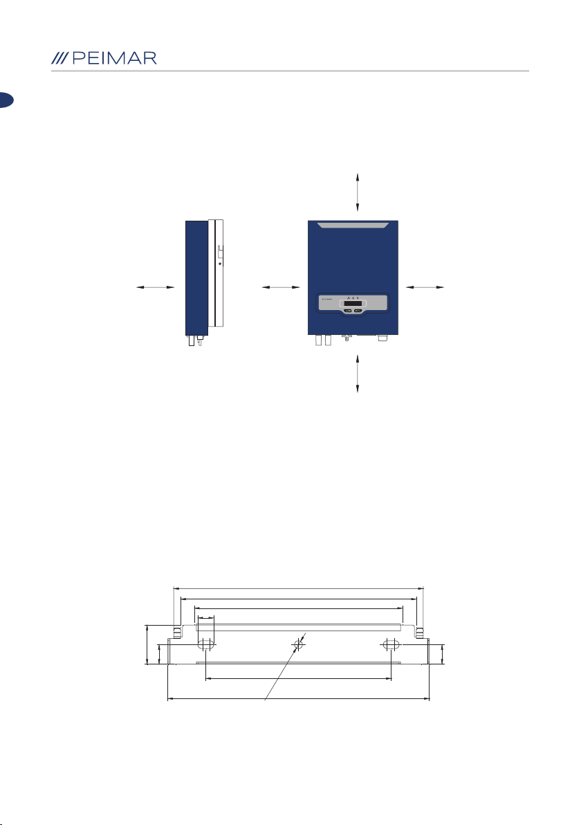
Per assicurare un’adeguata ventilazione nel luogo di installazione, in caso di
compresenza nella medesima area di diversi inverter fotovoltaici Peimar, è
necessario rispettare le distanze minime di sicurezza indicate nella Figura 4.2.
30 cm30 cm
30 cm 50 cm 50 cm
Figura 4.2 Distanze minime
4.4 Procedura di montaggio
4.4.1 Segnare i punti di perforazione per il montaggio della staffa di
ancoraggio
La posizione di montaggio deve essere segnata come mostrato nella Figura
4.3, Figura 4.4 e Figura 4.5.
252,9
16
40
20
Figura 4.3 Dimensioni della staffa di PSI-J1000-TL / PSI-J1500-TL
239
188
ø8
265
211
20
20

IT
296,9
40
20
Figura 4.4 Dimensioni della staffa di PSI-J2000-TL / PSI-J2500-TL / PSI-J3000-TL
Figura 4.5 Dimensioni della staffa di PSI-J3000-TLM / PSI-J4000-TLM / PSI-J5000-TLM / PSI-J6000-TLM
4-ø8
77,5 77,592
43
86
305
283
311
289
255
7,27,2
240
4.4.2 Perforare e posizionare i tasselli di ssaggio
Come da istruzioni, praticare nel muro i fori in corrispondenza dei punti segnati in
base alle indicazioni riportate nella Figura 4.6, Figura 4.7 e Figura 4.8.
Successivamente inserirvi i tasselli di ssaggio utilizzando un martello di gomma.
188
94
ø8
Figura 4.6 Dimensioni dei fori di PSI-J1000-TL / PSI-J1500-TL
21

IT
77,59 2
Figura 4.7 Dimensioni dei fori di PSI-J2000-TL / PSI-J2500-TL / PSI-J3000-TL
Figura 4.8 Dimensioni dei fori di PSI-J3000-TLM / PSI-J4000-TLM / PSI-J5000-TLM / PSI-J6000-TLM
247
240
ø8
120
ø8
4.4.3 Applicare le viti e montare la staffa di ancoraggio
Le staffe devono essere installate nella posizione di montaggio tramite viti come
mostrato nella Figura 4.9, Figura 4.10 e Figura 4.11.
Figura 4.9 Montaggio della staffa di PSI-J1000-TL / PSI-J1500-TL
22

Figura 4.10 Montaggio della staffa di PSI-J2000-TL / PSI-J2500-TL / PSI-J3000-TL
Figura 4.11 Montaggio della staffa di PSI-J3000-TLM / PSI-J4000-TLM / PSI-J5000-TLM / PSI-J6000-TLM
IT
23

IT
4.4.4 Montare l’inverter
Fissare con attenzione l’inverter alla staffa come mostrato nella Figura 4.12,
Figura 4.13 e Figura 4.14; assicurarsi che la parte posteriore del dispositivo
sia montata a stretto contatto con la staffa. Utilizzare le due viti apposite per
bloccare l’inverter alla staffa.
Figura 4.12 Montaggio dell’inverter PSI-J1000-TL / PSI-J1500-TL
Figura 4.13 Montaggio dell’inverter PSI-J2000-TL / PSI-J2500-TL / PSI-J3000-TL
Figura 4.14 Montaggio dell’inverter PSI-J3000-TLM / PSI-J4000-TLM / PSI-J5000-TLM / PSI-J6000-TLM
24

IT
Capitolo 5 - Connessione elettrica
5.1 Istruzioni di sicurezza per lavori sulla linea di alimentazione
La connessione elettrica deve essere effettuata esclusivamente da tecnici
professionisti. Si tenga presente che l’inverter è un dispositivo a doppia
alimentazione elettrica. Prima della connessione i tecnici devono munirsi dei
necessari dispositivi di protezione, tra cui guanti isolanti, scarpe isolanti e
casco protettivo.
PERICOLO
• Pericolo per la vita dovuto a rischio di incendio o scosse
elettriche.
• Al momento dell’accensione, il dispositivo deve essere
conforme alle norme e ai regolamenti nazionali.
• La connessione tra il convertitore e la rete di distribuzione
elettrica deve essere effettuata da tecnici qualicati in conformità
alle norme e ai regolamenti nazionali e locali della rete elettrica.
AVVERTENZA
• Quando l’impianto fotovoltaico è esposto alla luce, fornisce
all’inverter una tensione CC.
AVVISO
• La connessione elettrica deve essere effettuata a regola
d’arte, in conformità alle disposizioni normative riguardanti
la sezione dei conduttori, la protezione tramite fusibili o
interruttori automatici, e la messa a terra.
• La categoria di sovratensione all’ingresso CC è II, e quella
all’uscita CA è III.
25

5.2 Caratteristiche degli ingressi di connessione
Figura 5.1 Ingressi di connessione di PSI-J1000-TL / PSI-J1500-TL / PSI-J2000-TL / PSI-J2500-TL / PSI-J3000-TL
IT
Figura 5.2 Ingressi di connessione di PSI-J3000-TLM / PSI-J4000-TLM / PSI-J5000-TLM / PSI-J6000-TLM
A
B
C
D
Ingresso CC
Sezionatore CC
RS-232 / Porta Wi-Fi
Presa di connessione CA
Tabella 5.1 Ingressi di connessione
26

5.3 Connessione lato CA
IT
Sezione dei cavi (mm²)
Minimo-massimo Valore consigliato
Diametro esterno
dei cavi (mm)
4.0-6.0 4.0 4.2~5.3
Tabella 5.2 Caratteristiche raccomandate per i cavi CA
5.3.1 Inlare il cavo CA nel pressacavo impermeabile
Figura 5.3 Inlare il cavo
5.3.2 Connettere i cavi secondo i segni di connessione di L, N e PE
Figura 5.4 Connettere i cavi
5.3.3 Fissare saldamente tutte le parti del connettore CA
Figura 5.5 Avvitare il connettore
27

5.3.4 Connettere saldamente il connettore CA al dispositivo,
assicurandosi che gli spinotti siano direttamente connessi.
La connessione del cavo CA è in tal modo conclusa
Figura 5.6 Connettere l’inverter
5.4 Connessione dal lato CC
IT
Sezione dei cavi (mm²)
Minimo-massimo Valore consigliato
Diametro esterno
dei cavi (mm)
4.0-6.0 4.0 4.2~5.3
Tabella 5.3 Caratteristiche raccomandate per i cavi CC
La connessione CC è costituita dal connettore positivo e dal connettore negativo.
Vite di bloccaggio
Involucro isolante
Figura 5.7 Connettore positivo
28

IT
Vite di bloccaggio
Involucro isolante
Figura 5.8 Connettore negativo
AVVISO
• Posizionare separatamente il connettore dopo il
disimballaggio per evitare errori nella connessione dei cavi.
• Collegare il connettore positivo al polo positivo dei pannelli
solari, e il connettore negativo al polo negativo dei pannelli
solari. Assicurarsi che la connessione sia effettuata nella
corretta posizione.
Procedure di connessione:
1. Stringere le viti di bloccaggio sul connettore positivo e su quello negativo.
2. Utilizzare l’apposito attrezzo spelali per rimuovere la guaina isolante del
cavo positivo e di quello negativo per la lunghezza opportuna.
L2=8-10mm
L
=8-10mm
L
2
L
Figura 5.9 Connettere i cavi
Cavo positivo
1
Cavo negativo
1
29

IT
3. Inserire il cavo positivo e quello negativo nelle rispettive viti di bloccaggio.
4. Inserire i terminali metallici positivo e negativo nei rispettivi cavi a cui è
stato rimosso la guaina isolante, e bloccarli saldamente mediante una
pinza crimpatrice. Assicurarsi che la forza di estrazione del cavo pressato
sia superiore a 400N.
5. Inserire i cavi positivo e negativo crimpati nei rispettivi involucri isolanti;
si dovrebbe sentire o percepire uno scatto quando il cavo crimpato viene
posizionato correttamente.
6. Chiudere le viti di bloccaggio sui connettori positivi e negativi nel rispettivo
involucro isolante e stringerle.
7. Collegare i connettori positivo e negativo nei rispettivi terminali di ingresso
CC dell’inverter; si dovrebbe sentire o percepire uno scatto quando i
connettori sono collegati correttamente.
Porta di connessione
Porta di connessione
Figura 5.10 Connettere l’inverter
AVVISO
• Prima di inserire il connettore nel terminale di ingresso CC
dell’inverter, assicurarsi che l’interruttore CC dell’inverter sia
spento.
30

5.5 Connessione dell’interfaccia di comunicazione
Gli inverter Mirus, Unicus e Geminus sono dotati di un’interfaccia RS-232.
2 1
6574839
Figura 5.11 Porta seriale a 9 pin
IT
1. DCD (Data Carrier Detect)
2. RxD (Received Data)
3. TxD (Transmitted Ready)
4. DTR (Data Terminal)
6. DSR (Data Send Ready)
7. RTS (Request To Send)
8. CTS (Clear To Send)
9. RI (Ring Indicator)
5. GND (Signal Ground)
Tabella 5.5 Istruzioni di cablaggio della porta seriale a 9 pin
La porta RS-232 può essere connessa esternamente al modulo Wi-Fi.
Per ulteriori dettagli, fare riferimento alla relativa guida (allegata al dispositivo o
scaricabile dal sito www.peimar.com)
31

Capitolo 6 - Istruzioni per il debugging
6.1 Presentazione dell’interfaccia uomo-macchina
AFB C
E
Figura 6.1 Interfaccia uomo-macchina
IT
D
A
ALIMENTAZIONE
B
C
FUNZIONAMENTO
D
E
F
LED giallo:
LED rosso:
ERRORE
LED verde:
DISPLAY
La spia gialla è accesa quando l’inverter è alimentato
La spia rossa si accende al rilevamento di un errore
La spia rossa si spegne dopo la risoluzione degli errori
La spia verde è accesa durante il normale funzionamento del
dispositivo
Il display mostra i dati operativi, le informazioni e i parametri
registrati
Tasto ▼ / Esci
Tasto ▲ / Invio
Tabella 6.1 Istruzioni dell’interfaccia
32

IT
I tasti presenti sull’inverter consentono di navigare nel menu per richiedere
informazioni sul funzionamento e sui parametri operativi. Questi due pulsanti
possono essere usati ripetitivamente.
Premere per
meno di 1 secondo
Premere per
più di 1 secondo
Premere per
meno di 1 secondo
Premere per
più di 1 secondo
Tabella 6.2 Istruzioni per i tasti
Sposta in basso il cursore o riduce il valore
numerico selezionato
Torna al menu precedente o cancella il
comando selezionato
Sposta in alto il cursore o aumenta il valore
numerico selezionato
Entra nel sotto-menu selezionato, o conferma
il comando
6.2 Congurazione al primo avvio
6.2.1 Impostare la lingua
Quando l’inverter fotovoltaico inizia a funzionare per la prima volta, deve essere
selezionata la lingua di utilizzo. Il display dell’inverter apparirà come mostrato
di seguito:
Please set the
language rst
Figura 6.2 Impostare la lingua
Premere il tasto “ENT”: il display mostrerà la lingua da selezionare. Premendo
i tasti “▼” o “▲” spostare il cursore “>” no a selezionare la lingua corretta, e
premere quindi il pulsante “ENT” per confermare la selezione.
In seguito deve essere selezionato il Paese di utilizzo. Il display dell’inverter
apparirà come mostrato di seguito:
Selezionare
il Paese
Figura 6.3 Impostare il paese
33

IT
Premere il tasto “ENT”: il display mostrerà le opzioni di Paese da selezionare.
Premendo i tasti “▼” o “▲” spostare il cursore “>” no a selezionare il Paese
corretto, e premere quindi il pulsante “ENT” per confermare la selezione. In
seguito impostare data e ora.
Attenzione: la scelta del Paese di utilizzo deve essere effettuata al primo
avvio, prima che l’inverter entri in funzione. Una scelta errata comporta un mal
funzionamento del dispositivo. Per vericare la scelta effettuata accedere al
menu “Info Inverter > Standard Rete”.
Se il Paese di utilizzo non è presente tra le opzioni disponibili, interrompere la
congurazione e rivolgersi all’assistenza tecnica Peimar.
6.2.2 Stato
Se il Paese è stato impostato, quando l’inverter viene avviato il display mostra
il tipo di dispositivo e visualizza automaticamente lo stato operativo dell’inverter
tra uno dei seguenti: Normale, Attesa, Errore, Aggiornamento.
Normale
Attesa
Errore
Aggiornamento
Inverter in funzionamento normale
Inverter in stato di stand-by
Si è vericato un errore durante il funzionamento
Stato di aggiornamento rmware
Alimentare l’inverter lato CA, il display mostrerà il conto alla rovescia in secondi.
L’inverter inizierà la procedura di connessione alla rete elettrica.
Connessione rete
Attendere 30s
Figura 6.4 Conto alla rovescia in secondi
34

Note:
IT
35

6.3 Display dell’inverter
Inverter di rete
PSI-Jxxxx-xx
IT
2018/10/30 17:23
Stato Normale
P-ca 344 W
V-ca 227.9 V
I-ca 1.58 A
f-ca 50.03 Hz
V-PV1 170.5 V
I-PV1 2.36 A
V-PV2 0.0 V
I-PV2 0.00 A
Temp. 28.8 °C
ENT
E-oggi 0.00 kWh
P-ca 21 W
2018/10/30 17:23
Stato Normale
ENT
36
> Valori attuali
Statistiche
> Errore attuale
Storico Errori
> Imp. parametri
Info inverter
> Periferica
Auto test
> IP
0.0.0.0
...........
ENT
ENT
ENT

ENT
ENT
> E-Oggi
E-Mese
> E-Anno
E-Totale
> T-Oggi
T-Totale
Errore 24
...........
ENT
ENT
ENT
ENT
ENT
ENT
IT
E-Oggi 0.00 kWh
E-Mese 0.00 kWh
01/10 0.00 kWh
E-Anno 0.00 kWh
Gen. 0.00 kWh
E-Totale 0.01 kWh
2018 0.01 kWh
T-Oggi
0.5 h
T-Totale
0.5 h
ENT
> 18/10/30 13:20
18/09/30 10.23
...........
> Lingua
Data
Ora
> Standard Rete
> Cambia Password
Cancella Errori
> Azzera energia
Reset fabbrica
> IndirizzoMODBUS
Baud Rate
ENT
Errore 24
ENT
Prego inserire
Password:
ENT
Prego inserire
Password:
> Modello Inverter
Standard Rete
> Numero di serie
Codice Prodotto
> Vers. Firmware
Errore 24
******
******
37
ENT
ENT
ENT
ENT
ENT
ENT
ENT
> 1 Australia
2 Austria
...........
Inserire nuova
Password:
Modello Inverter
PSI-Jxxxx-xx
SN: xxxxxxxxxxxxx
PC: xxxxxxxxxxxxx
MCUF: Vx.xxx
SCUF: Vx.xxx
DBF: Vx.xxx
******
Italia 0-21
CEI0_21

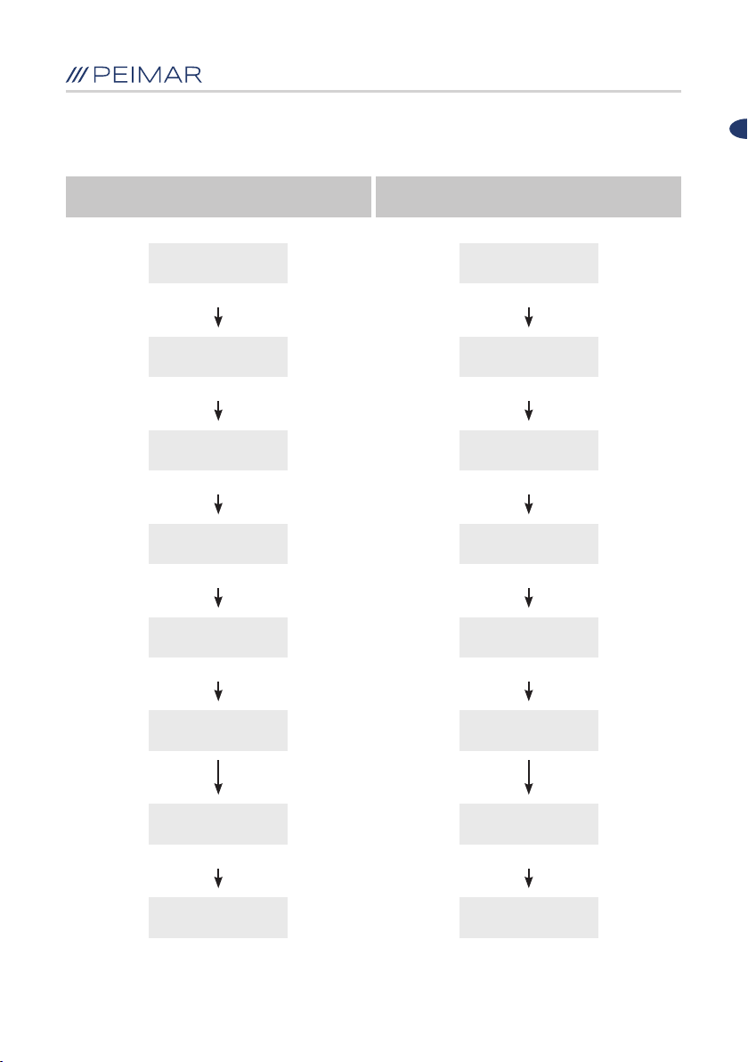
6.4 Impostare i parametri generali dell’inverter
Impostare la lingua Impostare la data
IT
E-oggi 0.00 kWh
P-ca 21 W
ENT
> Valori attuali
Statistiche
▼ ▼
> Imp. parametri
Info inverter
ENT
> Lingua
Data
ENT
Lingua [x]
x Italiano
ENT
Confermare le
modiche?
ENT
E-oggi 0.00 kWh
P-ca 21 W
ENT
> Valori attuali
Statistiche
> Imp. parametri
Info inverter
ENT
> Lingua
Data
▼
Lingua
> Data
ENT
Data 2018/10/30
ENT
Set Completato!
Confermare le
modiche?
ENT
Set Completato!
38

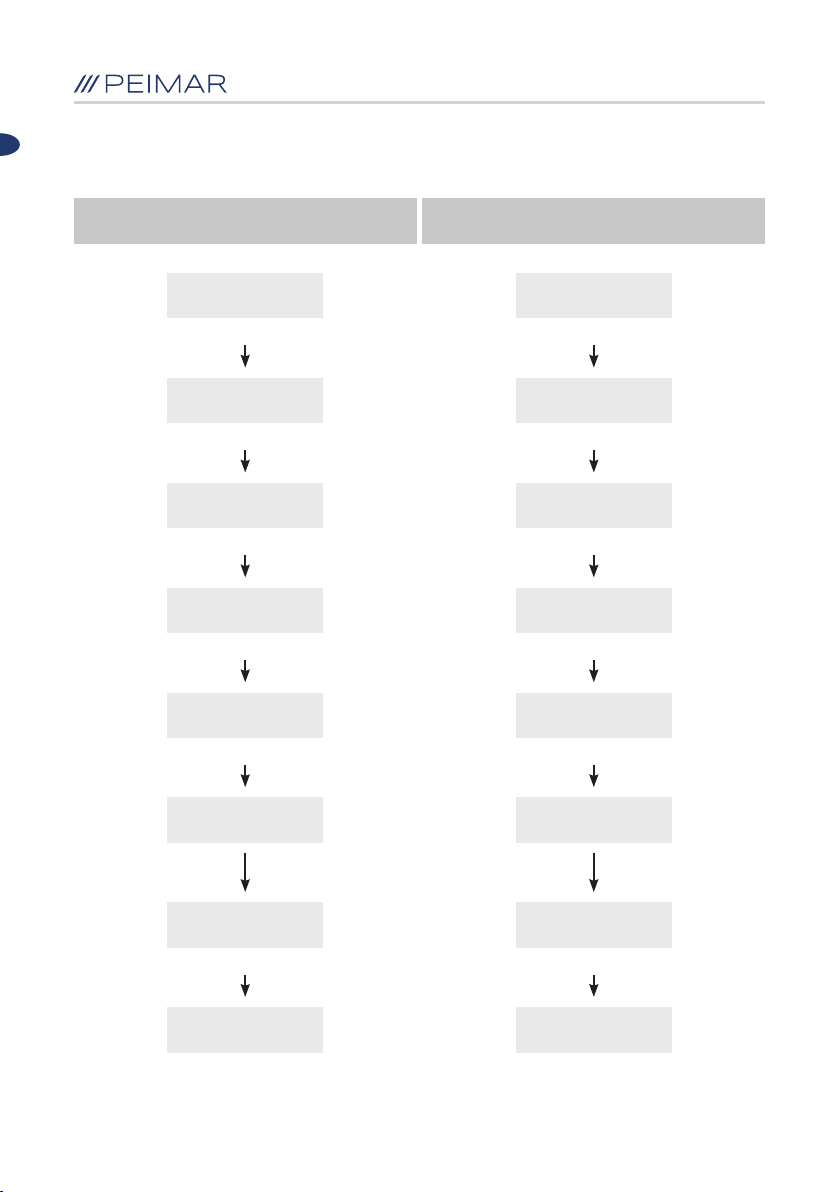
Impostare l’orario Reimpostare il paese
IT
E-oggi 0.00 kWh
P-ca 21 W
ENT
> Valori attuali
Statistiche
▼
> Imp. parametri
Info inverter
ENT
> Lingua
Data
▼
> Ora
Standard Rete
ENT
Ora: 15:35:23
ENT
E-oggi 0.00 kWh
P-ca 21 W
ENT
> Valori attuali
Statistiche
▼
> Imp. parametri
Info inverter
ENT ENT
> Lingua
Data
▼
Ora
> Standard Rete
ENT
Prego inserire
Password:
******
ENT
> 15 Italia 0-21
16 Portogallo
ENT
Confermare le
modiche?
Set Completato!
L’inverter si riavvia
automaticamente
Confermare le
modiche?
ENT
Set Completato!
> 1 Australia
2 Austria
▼
Attenzione password predenita: “123456”
39

Reimpostare la password Cancellare il registro errori
IT
E-oggi 0.00 kWh
P-ca 21 W
ENT
> Valori attuali
Statistiche
▼
> Imp. parametri
Info inverter
ENT
> Lingua
Data
▼
> Cambia Password
Cancella Errori
ENT
Prego inserire
Password:
******
ENT
Imposta nuova
password:
Set Completato!
******
ENT
E-oggi 0.00 kWh
P-ca 21 W
ENT
> Valori attuali
Statistiche
▼
> Imp. parametri
Info inverter
ENT
> Lingua
Data
▼
Cambia Password
> Cancella Errori
ENT
Prego inserire
Password:
******
ENT
Inserire nuova
Password:
Attenzione password predenita: “123456”
******
ENT
Confermare le
modiche?
ENT
Set Completato!
40

Azzerare l’energia Impostazioni di fabbrica
IT
E-oggi 0.00 kWh
P-ca 21 W
ENT
> Valori attuali
Statistiche
▼
> Imp. parametri
Info inverter
ENT
> Lingua
Data
▼
> Azzera energia
Reset fabbrica
ENT
Prego inserire
Password:
******
ENT
E-oggi 0.00 kWh
P-ca 21 W
ENT
> Valori attuali
Statistiche
▼
> Imp. parametri
Info inverter
ENT
> Lingua
Data
▼
Azzera energia
> Reset fabbrica
ENT
Prego inserire
Password:
******
ENT
Confermare le
modiche?
ENT
Set Completato!
L’inverter si riavvia
automaticamente
Confermare le
modiche?
ENT
Set Completato!
Attenzione password predenita: “123456”
41

6.5 Auto test completo dell’inverter
(Solo nei casi in cui il paese impostato sia “Italia 0-21”)
Comando test completo
> Valori attuali
Statistiche
▼
IT
Periferica
> Auto test
ENT
> 1 Ovp(59.S2)
2 Ovp10(59.S1)
ENT
▼
> 9 Test completo
ENT
▲
Test completo [0]
[0] risultato
▲ ▼
Test completo [1]
[1] test
ENT
9 Test completo
Attendere 2499s
Test superato!
ENT
TestCompleto [0]
[0] risultato
ENT
1 Ovp(59.S2)
Vt264.5V Tt200ms
ENT
▼
1 Ovp(59.S2)
Vs230.7V To190ms
...........
▼
2018/10/29 08:00
42

6.6 Auto test singoli dell’inverter
(Solo nei casi in cui il paese impostato sia “Italia 0-21”)
Test di massima tensione (59.S2)
Test di massima tensione
(59.S1, a media mobile su 10 min)
IT
> Valori attuali
Statistiche
▼
Periferica
> Auto test
ENT
> 1 Ovp(59.S2)
2 Ovp10(59.S1)
ENT
Ovp(59.S2) [0]
[0] risultato
▲
Ovp(59.S2) [1]
[1] test
ENT
1 Ovp(59.S2)
Attendere 599s
TestCompleto [0]
[0] risultato
ENT
1 Ovp(59.S2)
Vt264.5V Tt200ms
▼
Vs230.7V To190ms
Vo230.2V Pass
▼
2018/10/29 08:00
> Valori attuali
Statistiche
▼
Periferica
> Auto test
ENT
1 Ovp(59.S2)
> 2 Ovp10(59.S1)
ENT
Ovp10(59.S1) [0]
[0] risultato
▲
Ovp10(59.S1) [1]
[1] test
ENT
2 Ovp10(59.S1)
Attendere 599s
Test superato!
ENT
Test superato!
ENT
...........
43

Test di minima tensione (27.S1) Test di minima tensione (27.S2)
IT
> Valori attuali
Statistiche
▼
Periferica
> Auto test
ENT
> 3 Uvp(27.S1)
4 Uvp2(27.S2)
ENT
Uvp(27.S1) [0]
[0] risultato
▲
Uvp(27.S1) [1]
[1] test
ENT
3 Uvp(27.S1)
Attendere 599s
> Valori attuali
Statistiche
▼
Periferica
> Auto test
ENT
3 Uvp(27.S1)
> 4 Uvp2(27.S2)
ENT
Uvp2(27.S2) [0]
[0] risultato
▲
Uvp2(27.S2) [1]
[1] test
ENT
4 Uvp2(27.S2)
Attendere 599s
Test superato!
ENT
...........
Test superato!
ENT
...........
44
Test di massima frequenza (81>.S1) Test di massima frequenza (81>.S2)
IT
> Valori attuali
Statistiche
▼ ▼
Periferica
> Auto test
ENT ENT
> 5 Ofp(81>.S1)
6 Ofp2(81>.S2)
ENT ENT
Ofp(81>.S1) [0]
[0] risultato
▲
Ofp(81>.S1) [1]
[1] test
ENT ENT
5 Ofp(81>.S1)
Attendere 599s
> Valori attuali
Statistiche
Periferica
> Auto test
5 Ofp(81>.S1)
> 6 Ofp2(81>.S2)
Ofp2(81>.S2) [0]
[0] risultato
ENT
Ofp2(81>.S2) [1]
[1] test
6 Ofp2(81>.S2)
Attendere 599s
Test superato! Test superato!
ENTENT
......................
45
Test di minima frequenza (81<.S1) Test di minima frequenza (81<.S2)
IT
> Valori attuali
Statistiche
▼ ▼
Periferica
> Auto test
ENT ENT
> 7 Ufp(81<.S1)
8 Ufp2(81<.S2)
ENT ENT
Ufp(81<.S1) [0]
[0] risultato
▲ ▲
Ufp(81<.S1) [1]
[1] test
ENT ENT
7 Ufp(81<.S1)
Attendere 599s
> Valori attuali
Statistiche
Periferica
> Auto test
7 Ufp(81<.S1)
> 8 Ufp2(81<.S2)
Ufp2(81<.S2) [0]
[0] risultato
Ufp2(81<.S2) [1]
[1] test
8 Ufp2(81<.S2)
Attendere 599s
Test superato! Test superato!
ENT ENT
........... ...........
46

IT
Nota:
1. Questa operazione deve essere effettuata soltanto quando l’inverter è
connesso alla rete elettrica.
2. “Test Completo” comprende le prove dalla 1 alla 8 dell’Auto test.
3. I risultati dell’Auto test possono essere visualizzati dopo l’esito positivo
dell’operazione.
4. Eseguito il test completo, è possibile consultare tutti i risultati dei test.
6.7 Operazione di monitoraggio
Il dispositivo è equipaggiato con un’interfaccia RS-232. Essa può essere
connessa al modulo Wi-Fi, utlizzabile per il monitoraggio dello stato di
funzionamento.
• Il dispositivo può connettersi alla rete internet locale tramite un modulo Wi-Fi ed
il web server integrato nel dispositivo; in tal modo si può monitorare lo stato di
funzionamento dell’inverter.
• Connettendosi alla rete internet tramite il modulo Wi-Fi e caricando i dati
dell’inverter sul server, gli utenti possono monitorare le informazioni di
funzionamento da remoto.
47

Capitolo 7 - Codici di errore e risoluzione dei problemi
7.1 Codice errore e descrizione
IT
Errore 01
Errore 02
Errore 03
Errore 04
Errore 05
Errore 06
Errore 07
Errore 08
Errore 09
Errore 10
Errore 15
Errore 18
Errore 19
Errore 24
Errore 27
Errore 28
Errore 31
Errore 33
Errore 35
Errore 38
Errore 39
Errore 40
Errore 41
Errore 50
Errore 51
Errore relè (Master)
Errore memoria EEPROM (Master)
Temperatura elevata (Master)
Temperatura bassa (Master)
Comunicazione interna persa (Master)
Errore dispositivi GFCI (Master)
Errore dispositivi DCI (Master)
Errore sensore di corrente (Master)
Tensione di rete elevata (Master)
Tensione di rete bassa (Master)
Tensione media di 10 minuti elevata (Master)
Frequenza elevata (Master)
Frequenza bassa (Master)
Errore di rete elettrica persa (Master)
Errore GFCI (Master)
Errore DCI (Master)
Errore di isolamento ISO (Master)
Tensione Bus elevata (Master)
Corrente elevata (Master)
Tensione Bus dell’Hardware elevata (Master)
Corrente PV1 dell’Hardware elevata (Master)
Corrente PV2 dell’Hardware elevata (Master)
Corrente dell’Hardware di rete elevata (Master)
Comunicazione interna persa (Slave)
Errore di coerenza dei dati di tensione (Slave)
48

Errore 57
Errore 61
Errore 62
Errore 67
Errore 68
Errore 73
Errore 76
Errore 77
Errore 81
IT
Errore di coerenza dei dati di frequenza (Slave)Errore 54
Errore coerenza dati GFCI (Slave)
Tensione della rete elettrica elevata (Slave)
Tensione della rete elettrica bassa (Slave)
Frequenza elevata (Slave)
Frequenza bassa (Slave)
Errore di assenza di rete elettrica (Slave)
Tensione PV1 elevata (Slave)
Tensione PV2 elevata (Slave)
Comunicazione persa tra scheda di visualizzazione
e scheda di controllo (Slave)
Errore 85
Errore DRM0 (Slave)
Tabella 7.1 Codici di errore
7.2 Indicazione errore e Risoluzione del problema
Errore relè
Errore memoria
EEPROM
Temperatura elevata
Errore dispositivo GFCI
Errore dispositivi DCI
Se questo errore si verica spesso, siete pregati di contattare il
vostro rivenditore o l’assistenza tecnica Peimar.
Se questo errore si verica spesso, siete pregati di contattare il
vostro rivenditore o l’assistenza tecnica Peimar.
Vericare che il dissipatore non sia bloccato e che l’inverter non
abbia una temperatura troppo alta o troppo bassa; se le suddette
condizioni sono nella norma, siete pregati di contattare il vostro
rivenditore o l’assistenza tecnica Peimar.
Se questo errore si verica spesso, siete pregati di contattare il
vostro rivenditore o l’assistenza tecnica Peimar.
Se questo errore si verica spesso, siete pregati di contattare il
vostro rivenditore o l’assistenza tecnica Peimar.
49

IT
Errore sensore
di corrente
Errore di
tensione di rete
Errore di frequenza
Errore di assenza di
rete elettrica
Errore GFCI
Errore DCI
Se questo errore si verica spesso, siete pregati di contattare il
vostro rivenditore o l’assistenza tecnica Peimar.
• Controllare la tensione della rete elettrica.
• Controllare la connessione tra l’inverter e la rete elettrica.
• Controllare le impostazioni di standard di rete nell’inverter.
• Se la tensione della rete elettrica è più alta della tensione
standard, rivolgersi al distributore di rete locale per la
regolazione della tensione al punto di immissione o per
modicare il valore della tensione regolata.
• Se la tensione della rete elettrica rientra nel range consentito
e il display mostra ancora questo errore, siete pregati di
contattare il vostro rivenditore o l’assistenza tecnica Peimar.
Controllare l’impostazione del Paese e la frequenza della rete
elettrica locale; se le suddette condizioni sono nella norma, siete
pregati di contattare il vostro rivenditore o l’assistenza tecnica Peimar.
Controllare lo stato di connessione tra il lato CA dell’inverter e la
rete elettrica; se le condizioni sono nella norma, siete pregati di
contattare il vostro rivenditore o l’assistenza tecnica Peimar.
Controllare la resistenza di isolamento del lato positivo e del lato
negativo dei pannelli solari; vericare che l’inverter non si trovi in un
ambiente bagnato; controllare la corretta messa a terra dell’inverter.
Se le suddette condizioni sono nella norma, siete pregati di
contattare il vostro rivenditore o l’assistenza tecnica Peimar.
Se questo errore è sempre presente, siete pregati di contattare il
vostro rivenditore o l’assistenza tecnica Peimar.
Errore di
isolamento ISO
Corrente elevata
Tensione Bus elevata
Controllare la resistenza di isolamento del lato positivo e del lato
negativo dei pannelli solari; vericare che l’inverter non si trovi in un
ambiente bagnato; controllare la corretta messa a terra dell’inverter.
Se le suddette condizioni sono nella norma, siete pregati di
contattare il vostro rivenditore o l’assistenza tecnica Peimar.
Controllare lo stato di connessione tra l’inverter e la rete elettrica e
vericare se la tensione della rete elettrica è stabile o meno. Se le
suddette condizioni sono nella norma, siete pregati di contattare il
vostro rivenditore o l’assistenza tecnica Peimar.
Controllare le impostazioni dei pannelli solari. I tecnici Peimar
possono aiutarvi. Se le suddette condizioni sono nella norma, siete
pregati di contattare il vostro rivenditore o l’assistenza tecnica Peimar.
50

IT
Corrente PV elevata
Errore di tensione PV
Comunicazione persa
Se questo errore è sempre presente, siete pregati di contattare il
vostro rivenditore o l’assistenza tecnica Peimar.
Controllare le impostazioni dei pannelli solari. I tecnici Peimar
possono aiutarvi. Se le suddette condizioni sono nella norma, siete
pregati di contattare il vostro rivenditore o l’assistenza tecnica Peimar.
Controllare la connessione dei cavi di comunicazione tra la
scheda di controllo e la scheda di visualizzazione. Se le suddette
condizioni sono nella norma, siete pregati di contattare il vostro
rivenditore o l’assistenza tecnica Peimar.
Tabella 7.2 Risoluzione dei problemi
51

IT
Capitolo 8 - Riciclaggio e Smaltimento
Questo dispositivo non deve essere smaltito come riuto urbano. Quando
un inverter ha raggiunto la ne della sua vita utile e non è più utilizzabile,
è necessario restituirlo al proprio rivenditore o smaltirlo presso un centro
autorizzato di raccolta e riciclaggio nella propria zona.
Capitolo 9 - Servizio di Garanzia
Per le condizioni di garanzia fare riferimento al relativo documento scaricabile
dal sito internet www.peimar.com
52

Note:
IT
53


EN
Thank you for choosing a Peimar solar inverter. We aim to provide you with rstclass quality products and exceptional technical service.
This manual includes all relevant information for the installation, operation,
maintenance, trouble shooting and safety of the Peimar inverter. Please follow
the instructions on this manual closely to ensure that this product meets all
safety requirements and that you are able to obtain as much benet and long
life from it as possible.
At Peimar, we are fully committed to delivering superior customer experience
and hope that this document becomes the rst steps of your journey towards a
cleaner and greener world.
Please check for the latest version at www.peimar.com
It is important to point out, that all technical specications, information and gures contained in this document are estimated values.
Peimar reserves the right to change the technical specications, information and gures contained in this document at any time and
without notice.
55

Content
Chapter 1
Safety precautions .............................................................................58
1.1 Scope of application .............................................................58
1.2 Safety instructions ................................................................58
1.3 Target group .......................................................................... 58
Chapter 2
Preparation ..........................................................................................59
2.1 Safety instructions ................................................................ 59
2.2 Explanations of symbols ......................................................60
Chapter 3
Product information ...........................................................................62
3.1 Application scope of products ..............................................62
3.2 Specication for product model ............................................63
3.3 Overview and dimensions of products .................................63
3.4 Datasheet - MIRUS LINE .....................................................64
3.5 Datasheet - UNICUS LINE ................................................... 66
3.6 Datasheet - GEMINUS LINE ................................................ 68
EN
Chapter 4
Instructions for installation ...............................................................70
4.1 Safety instructions ................................................................ 70
4.2 Pre-installation check ...........................................................70
4.3 The determination of the installation method and position ... 71
4.4 Mounting procedure .............................................................72
Chapter 5
Electrical connection .........................................................................77
5.1 Safety instruction for hot-line job .......................................... 77
5.2 Specications for electrical interface ....................................78
5.3 AC side connection ..............................................................79
56

5.4 DC side connection .............................................................. 80
5.5 Communication connection .................................................. 83
Chapter 6
Debugging instructions .....................................................................84
6.1 Introduction of human-computer interface ............................ 84
6.2 First run setup ......................................................................85
6.3 Display of the inverter ...........................................................88
6.4 Settings of general parameters of the inverter .....................90
6.5 Complete Selftest of the inverter .......................................... 94
6.6 Individual Selftest of the inverter ..........................................95
6.7 Monitoring operation ............................................................99
Chapter 7
Fault code and troubleshooting ..................................................... 100
7.1 Fault code and explanation ................................................. 100
7.2 Fault information and troubleshooting ................................. 101
EN
Chapter 8
Recycling and Disposal ................................................................... 104
Chapter 9
Guarantee Service ............................................................................ 104
57

EN
Chapter 1 - Safety precautions
1.1 Scope of application
This User Manual describes instructions and detailed procedures for installing,
operating, maintaining, and troubleshooting of the following Peimar grid-tied
inverters:
PSI-J1000-TL PSI-J1500-TL PSI-J2000-TL PSI-J2500-TL PSI-J3000-TL
PSI-J3000-TLM PSI-J4000-TLM PSI-J5000-TLM PSI-J6000-TLM
Please keep this manual all time available in case of emergency.
1.2 Safety instructions
DANGER indicates a hazardous situation which, if not
avoided, will result in death or serious injury.
WARNING indicates a hazardous situation which, if
not avoided, can result in death or serious injury or
moderate injury.
CAUTION indicates a hazardous condition which, if
not avoided, can result in minor or moderate injury.
NOTICE indicates a situation that can result in potential
damage, if not avoided.
1.3 Target group
Only qualied electricians who have read and fully understood all safety
regulations contained in this manual can install, maintain and repair the inverter.
Operators must be aware of the high-voltage device.
58

2.1 Safety instructions
DANGER
• There is possiblity of duing to electrical shock and high
voltage may cause death.
• Do not touch the operating component of the inverter, or it
might result in burning or death.
• To prevent risk of electric shock during installation and
maintenance, please make sure that all AC and DC terminals
are plugged out.
• Do not touch the surface of the inverter while the housing is
wet, or it might lead to electrical shock.
• Do not stay close to the inverter while there are severe
weather conditions including storm, lighting, etc.
• Before opening the housing, the Peimar inverter must be
disconnected from the grid and PV generator; you must wait
for at least ve minutes to let the energy storage capacitors
fully be discharged after disconnecting from power source.
EN
Chapter 2 - Preparation
WARNING
• The installation,service, recycling and disposal of the inver ters
must be performed by qualied personnel only in compliance
with national and local standards and regulations.
• Any unauthorized actions including modication of
product functionality of any form may cause lethal hazard
to the operator, third parties, the units or their property.
Peimar is not responsible for the loss and these warranty
claims.
• The Peimar inverter must only be operated with PV generator.
Do not connect any other source of energy to the Peimar
inverter.
• Be sure that the PV generator and inverter are well grounded
in order to protect safety of people’s life and property.
59
CAUTION
• The PV inverter will become hot during operation. Please do
not touch the heat sink or peripheral surface during or shortly
after operation.
• Risk of damage due to improper modications.
NOTICE
• The PV inverter is designed to feed AC power directly to
the public utility power grid; do not connect AC output of the
inverter to any private AC equipment.
2.2 Explanations of symbols
DANGEROUS ELECTRICAL VOLTAGE
This device is directly connected to public grid, thus all work
to the inverter shall only be carried out by qualied personnel.
DANGER to life due to high electrical voltage!
There might be residual currents in inverter because of large
capacitors.
Wait for 5 MINUTES before you remove the front lid.
EN
NOTICE, DANGER!
This is directly connected with electricity generators and
public grid.
DANGER OF HOT SURFACE
The components inside the inverter will release a lot of heat
during operation. Do not touch metal plate housing during
operating.
60

EN
AN ERROR HAS OCCURRED
Please go to Chapter 7 “Troubleshooting” to remedy the error.
This device SHALL NOT be disposed of as residential waste.
Please go to Chapter 8 “Recycling and Disposal” for proper
treatments.
ROHS
Restriction of Hazardous Substances Directive
WITHOUT TRANSFORMER
This inverter does not use transformer for the isolation
function.
GROUNDING
Point of connection for grounding protection.
CE MARK
Equipment with the CE mark fullls the basic requirements of
the Guideline Governing Low-Voltage and Electro-magnetic
Compatibility.
61

EN
Chapter 3 - Product information
3.1 Application scope of products
Mirus, Unicus, Geminus series products are grid-tied single phase inverters
without transformers, and the inverters are important components of grid-tied
solar power systems.
The Mirus, Unicus, Geminus inverters change the DC generated by solar
panels into AC which is in accordance with the requirements of public grid and
send the AC into the grid, Table 3.1 shows the structural diagram of the typical
application system of PSI-J inverters.
A B C D
A
B
C
D
Solar panels
Inverters
Metering equipment
Power grid
Table 3.1 Systematic conguration diagram
Monocrystalline or polycrystalline silicon, and thin-lm PV
modules with II protection and need no ground connection
Mirus, Unicus e Geminus
Standard metering tool for measuring the output electric
power of inverters
Types of power grid: TT, TN-C, TN-S, TN-C-S
62
3.2 Specication for Product Model
PSI-JXXXX-TL PSI-JXXXX-TLM
• PSI-J represents the product name
• XXXX represents the rated power in W of the inverter
• TL represents that the inverter is transformerless
• M represents that the inverter has the function of dual MPPT
3.3 Overview and Dimensions of products
The dimensions of products is shown in Figure 3.2.
260 mm 120 mm
EN
315 mm
SERIES
UNICUS
355 mm 150/162 mm
454
SERIES
MIRUS
305 mm 120
PSI-J2000-TL
PSI-J2500-TL
PSI-J3000-TL
354 mm
SERIES
GEMINUS
Figure 3.2 Dimensions of Mirus, Unicus, Geminus series
PSI-J1000-TL
PSI-J1500-TL
PSI-J3000-TLM
PSI-J4000-TLM
PSI-J5000-TLM
PSI-J6000-TLM
63

3.4 Datasheet - MIRUS LINE
EN
Input DC
Max. DC Power
Max. DC Voltage
MPPT Voltage range
Nominal DC Voltage
Start Voltage
Min. DC Voltage
Max. DC Input Current
Number of DC Connection
Sets per MPPT
Number of MPPT
DC Switch
Output AC
Rated AC Power
Max. AC Power
Rated AC Current
Max. AC Current
Nominal AC voltage / Range
Grid frequency / range
Power factor [cos φ]
Total Harmonic Distortion
Feed in
PSI-J1000-TL PSI-J1500-TL
1200 W
450 V
60-425 V
360 V
70 V
50 V
11 A
1 1
1
Integrated
1000 W
1100 W
4.3 A
5.3 A
220 V, 230 V, 240 V / 180 V - 280 V
50 Hz, 60 Hz / ±5 Hz
> 0.99 (full load)
< 3%
1L + N + PE
1800 W
450 V
60-425 V
360 V
70 V
50 V
11 A
1
Integrated
1500 W
1650 W
6.5 A
7.9 A
Protection
Internal Over-voltage Protection
DC Insulation Monitoring
DCI Monitoring
GFCI Monitoring
Grid Monitoring
AC Short Circuit Current Protection
Thermal Protection
Anti-island protection monitoring
Integrated
Integrated
Integrated
Integrated
Integrated
Integrated
Integrated
AFD
64

Efficiency
Max. Efficiency
Euro Efficiency
MPPT Accuracy
Interface
AC Connection
DC Connection
LCD
LED Display
Display Language
Datalogger & Communication
General Data
Topology
Consumption at Night
Consumption at Standby
Operating Temperature Range
Cooling Method
Ambient Humidity
Altitude
Noise
Overvoltage Rating
Ingress Protection
Mounting
Dimensions (H x W x D) [mm]
Net Weight
Warranty [Year]
97.1%
96.6%
> 99.5%
Plug-in connector
MC4 / H4
LCD (16 x 2 characters, backlight)
LED (3 lights)
Italian / English / Spanish
RS-232 / Wi-Fi (opcional)
Transformerless
< 0.2 W
6 W
From -25 °C to + 60 °C (45 °C to 60 °C with derating)
Natural Convection
From 0% to 100% Non-condensing
Up to 2000 m (without derating)
< 15 dBA
II (DC input) III (AC output)
IP65 (Indoor & Outdoor Installation)
Rear Panel
315 x 260 x 120
5.6 kg
5 (standard) / 10 (optional)
97.2%
96.7%
> 99.5%
EN
Certicates
For a complete list of certicates visit www.peimar.com
65

3.5 Datasheet - UNICUS LINE
EN
Input DC
Max. DC Power
Max. DC Voltage
MPPT Voltage range
Nominal DC Voltage
Start Voltage
Min. DC Voltage
Max. DC Input Current
Number of DC Connection
Sets per MPPT
Number of MPPT
DC Switch
Output AC
Rated AC Power
Max. AC Power
Rated AC Current
Max. AC Current
Nominal AC voltage / Range
Grid frequency / range
Power factor [cos φ]
Total Harmonic Distortion
Feed in
PSI-J2000-TL PSI-J2500-TL PSI-J3000-TL
2400 W
500 V
60-450 V
360 V
70 V
50 V
11 A
1 1 1
1
Integrated
2000 W
2200 W
8.7 A
10.6 A
220 V, 230 V, 240 V / 180 V - 280 V
3000 W
500 V
60-450 V
360 V
70 V
50 V
11 A
1
Integrated
2500 W
2750 W
10.9 A
13.3 A
50 Hz, 60 Hz / ±5 Hz
> 0.99 (full load)
< 3%
1L + N + PE
3630 W
550 V
60-500 V
360 V
70 V
50 V
11 A
1
Integrated
3000 W
3300 W
13.0 A
15.9 A
Protection
Internal Over-voltage Protection
DC Insulation Monitoring
DCI Monitoring
GFCI Monitoring
Grid Monitoring
AC Short Circuit Current Protection
Thermal Protection
Anti-island protection monitoring
Integrated
Integrated
Integrated
Integrated
Integrated
Integrated
Integrated
AFD
66

Efficiency
Max. Efficiency
Euro Efficiency
MPPT Accuracy
Interface
AC Connection
DC Connection
LCD
LED Display
Display Language
Datalogger & Communication
General Data
Topology
Consumption at Night
Consumption at Standby
Operating Temperature Range
Cooling Method
Ambient Humidity
Altitude
Noise
Overvoltage Rating
Ingress Protection
Mounting
Dimensions (H x W x D) [mm]
Net Weight
Warranty [Year]
97.4%
96.9%
> 99.5%
LCD (16 x 2 characters, backlight)
From -25 °C to + 60 °C (45 °C to 60 °C with derating)
From 0% to 100% Non-condensing
Up to 2000 m (without derating)
II (DC input) III (AC output)
IP65 (Indoor & Outdoor Installation)
5 (standard) / 10 (optional)
97.5%
97.0%
> 99.5%
Plug-in connector
MC4 / H4
LED (3 lights)
Italian / English / Spanish
RS-232 / Wi-Fi
Transformerless
< 0.2 W
6 W
Natural Convection
< 15 dBA
Rear Panel
354 x 305 x 120
EN
97.6%
97.1%
> 99.5%
8.4 kg8.3 kg7.8 kg
Certicates
For a complete list of certicates visit www.peimar.com
67

3.6 Datasheet - GEMINUS LINE
EN
Input DC
Max. DC Power
Max. DC Voltage
MPPT Voltage range
Nominal DC Voltage
Start Voltage
Min. DC Voltage
Max. DC Input Current
Number of DC Connection
Sets per MPPT
Number of MPPT
DC Switch
Output AC
Rated AC Power
Max. AC Power
Rated AC Current
Max. AC Current
Nominal AC voltage / Range
Grid frequency / range
Power factor [cos φ]
Total Harmonic Distortion
Feed in
PSI-J6000-TLMPSI-J5000-TLMPSI-J4000-TLMPSI-J3000-TLM
3630 W
600 V
90-550 V
360 V
100 V
80 V
11 / 11 A
1 / 1 1 / 1 1 / 1 1 / 1
2
Integrated
3000 W
3300 W
13.0 A
15.9 A
4840 W
600 V
90-550 V
360 V
100 V
80 V
11 / 11 A
2
Integrated
1
3680
/ 4000 W
3680 / 4400 W
16.0 / 17.4 A
16.0 / 21.0 A
220 V, 230 V, 240 V / 180 V - 280 V
50 Hz, 60 Hz / ±5 Hz
0.8 leading ~ 0.8 lagging
1L + N + PE
Integrated
4600
4600 / 5500 W
20.0 / 21.7 A
22.2 / 26.7 A
< 3%
6050 W
600 V
90-550 V
360 V
100 V
80 V
11 / 11 A
2
2
/ 5000 W
7200 W
600 V
90-550 V
360 V
100 V
80 V
11 / 11 A
2
Integrated
6000 W
6000 W
26.1 A
28.7 A
Protection
Internal Over-voltage Protection
DC Insulation Monitoring
DCI Monitoring
GFCI Monitoring
Grid Monitoring
AC Short Circuit Current Protection
Thermal Protection
Anti-island protection monitoring
Integrated
Integrated
Integrated
Integrated
Integrated
Integrated
Integrated
AFD
68
Efficiency
Max. Efficiency
Euro Efficiency
MPPT Accuracy
Interface
AC Connection
DC Connection
LCD
LED Display
Display Language
Datalogger & Communication
General Data
Topology
Consumption at Night
Consumption at Standby
Operating Temperature Range
Cooling Method
Ambient Humidity
Altitude
Noise
Overvoltage Rating
Ingress Protection
Mounting
Dimensions (H x W x D) [mm]
Net Weight
Warranty [Year]
97.6%
97.1%
> 99.5%
From -25 °C to + 60 °C (45 °C to 60 °C with derating)
97.8%
97.4%
> 99.5%
Plug-in connector
MC4 / H4
LCD (16 x 2 characters, backlight)
LED (3 lights)
Italian / English / Spanish
RS-232 / Wi-Fi
Transformerless
< 0.2 W
Natural Convection
From 0% to 98% Non-condensing
Up to 2000 m (without derating)
< 25 dBA
II (DC input) III (AC output)
IP65 (Indoor & Outdoor Installation)
Rear Panel
454 x 355 x 150
14.8 kg
5 (standard) / 10 (optional)
97.9%
97.5%
> 99.5%
6 W
EN
97.9%
97.5%
> 99.5%
454 x 355 x 162
15.8 kg
Certicates
For a complete list of certicates visit www.peimar.com
1. Meet the grid standard that AC current per phase not exceeding 16A
2. Meet the VDE - ARN - N 4105 that biggest apparent power of single-phase is 4600 VA
69

Chapter 4 - Instructions for installation
4.1 Safety instructions
DANGER
• Dangerous to life due to potential re or electricity shock.
• Do not install the inverter near any inammable or explosive
items.
• This inverter will be directly connected with HIGH VOLTAGE
power generation device; the installation must be performed
by qualied personnel only in compliance with national and
local standards and regulations.
NOTICE
• This equipment is suitable for the pollution degree II.
• Inappropriate or unharmonized installation environment may
jeopardize the life span of the inverter.
• Installation directly exposed under intensive sunlight is not
recommended.
• The installation site must be well ventilated.
EN
4.2 Pre-installation check
4.2.1 Check the package
Although Peimar’s inverters have surpassed stringent testing and are checked
before they leave the factory, it is uncertain that the inverters may suffer damages
during transportation.
Please check the package for any obvious signs of damage, and if such
evidence is present, do not open the package and contact your dealer as soon
as possible.
4.2.2 Check the assembly parts
Please refer to the packing list inside the package container.
70

EN
4.3 The determination of the installation method and position
4.3.1 Mounting method
Please mount the inverter correctly as shown in Figure 4.1 below.
MAX 15°
Figure 4.1 Mounting method
1. The equipment employs natural convection cooling, and it can be installed
indoor or outdoor.
2. Please install the equipment under the guidance of Figure 4.1. Vertical
installation on oor level is recommended. Mount vertically or tilted
backwards by max. 15°. Never install the inverter tilted forwards, sideways,
horizontally or upside down.
3. Install the inverter at eye level for convenience when checking the LCD
display and possible maintenance activities.
4. When mounting the inverter, please consider that disassembly for service
work may be required.
4.3.2 Installation position
Do not expose the inverter to direct solar irradiation as this could cause power
derating due to overheating.
The ambient temperature should be between -25°C ~ +60°C (-13°F ~ 140°F) to
ensure optimum operation. Choose locations with sufficient air exchange.
Ensure additional ventilation, if necessary.
71

EN
To make sure the installation spot is suitably ventilated, if multiple Peimar gridtied solar inverters are installed same area, the following safety clearance in
Figure 4.2 Shall be followed for proper ventilation conditions.
30 cm30 cm
30 cm 50 cm 50 cm
Figure 4.2 Minimum clearance
4.4 Mounting procedure
4.4.1 Mark the positions of the drill holes of the rear panel
The mounting position should be marked as shown in Figure 4.3, Figure 4.4,
Figure 4.5.
252,9
16
40
20
Figure 4.3 Dimensions of rear panel of PSI-J1000-TL / PSI-J1500-TL
239
188
ø8
265
211
20
72

EN
296,9
40
20
Figure 4.4 Dimensions of rear panel of PSI-J2000-TL / PSI-J2500-TL / PSI-J3000-TL
Figure 4.5 Dimensions of rear panel of PSI-J3000-TLM / PSI-J4000-TLM / PSI-J5000-TLM / PSI-J6000-TLM
4-ø8
77,5 77,592
43
86
305
283
311
289
255
7,27,2
240
4.4.2 Drill holes and place the expansion tubes
According to the guides, drill holes in the wall in conformity with position marked
in Figure 4.6, Figure 4.7, Figure 4.8 and then place expansion tubes in the holes
using a rubber mallet.
188
94
ø8
Figure 4.6 Drill holes’ dimensions of PSI-J1000-TL / PSI-J1500-TL
73

EN
77,59 2
Figure 4.7 Drill holes’ dimensions of PSI-J2000-TL / PSI-J2500-TL / PSI-J3000-TL
Figure 4.8 Drill holes’ dimensions of PSI-J3000-TLM / PSI-J4000-TLM / PSI-J5000-TLM / PSI-J6000-TLM
247
240
ø8
120
ø8
4.4.3 Mount the screws and the rear panel
The panels should be mounted in the mounting position by screws as shown in
Figure 4.9, Figure 4.10, Figure 4.11.
Figure 4.9 Mount the rear panel of PSI-J1000-TL / PSI-J1500-TL
74

Figure 4.10 Mount the rear panel of PSI-J2000-TL / PSI-J2500-TL / PSI-J3000-TL
Figure 4.11 Mount the rear panel of PSI-J3000-TLM / PSI-J4000-TLM / PSI-J5000-TLM / PSI-J6000-TLM
EN
75

EN
4.4.4 Mount the inverter
Carefully mount the inverter to the rear panel as shown in Figure 4.12, Figure
4.13, Figure 4.14. Make sure that the rear part of the equipment is closely
mounted to the rear panel. Use the two specic screws to lock the inverter to
the rear panel.
Figure 4.12 Mount PSI-J1000-TL / PSI-J1500-TL
Figure 4.13 Mount PSI-J2000-TL / PSI-J2500-TL / PSI-J3000-TL
Figure 4.14 Mount PSI-J3000-TLM / PSI-J4000-TLM / PSI-J5000-TLM / PSI-J6000-TLM
76

EN
Chapter 5 - Electrical connection
5.1 Safety instruction for hot-line job
Electrical connection must only be operated on by professional technicians.
Please keep in mind that the inverter is a bi-power supply equipment.
Before connection, necessary protective equipment must be employed by
technicians including insulating gloves, insulating shoes and safety helmet.
DANGER
• Dangerous to life due to potential re or electricity shock.
• When power-on, the equipment should be in conformity with
national rules and regulations.
• The direct connection between the converter and high voltage
power systems must be operated by qualied technicians in
accordance with local and national power grid standards and
regulations.
WARNING
• When the photovoltaic array is exposed to light, it supplies a
DC voltage to the inverter.
NOTICE
• Electrical connection should be in conformity with proper
stipulations, such as stipulations for cross-sectional area of
conductors, fuse and ground protection.
• The overvoltage category on DC input port is II, and that on
AC output port is III.
77

5.2 Specications for electrical interface
Figure 5.1 Electrical interface of PSI-J1000-TL / PSI-J1500-TL PSI-J2000-TL / PSI-J2500-TL / PSI-J3000-TL
EN
Figure 5.2 Electrical interface of PSI-J3000-TLM / PSI-J4000-TLM / PSI-J5000-TLM / PSI-J6000-TLM
A
B
C
D
DC Input
DC Switch
RS-232 /Wi-Fi Port
AC Plug Terminal
Table 5.1 Specications for interface
78

5.3 AC side connection
EN
Cross-sectional Area of Cables (mm²)
Scope Recommended Value
Outside Diameter
of the Cables (mm)
4.0-6.0 4.0 4.2~5.3
Table 5.2 Recommended specications of AC cables
5.3.1 Feed the AC cable through the AC waterproof hole
Figure 5.3 Thread the cables
5.3.2 Connect the cables according to connection marks of L, N and PE.
Figure 5.4 Connect the cables
5.3.3 Secure all parts of the AC connector tightly.
Figure 5.5 Screw the connector
79

5.3.4 Connect the AC connector to the equipment securely, ensuring
the pins are connected directly.
Then the connection of AC cable is complete
Figure 5.6 Connect the inverter
5.4 DC side connection
EN
Cross-sectional Area of Cables (mm²)
Scope Recommended Value
Outside Diameter
of the Cables (mm)
4.0-6.0 4.0 4.2~5.3
Table 5.3 Recommended specications of DC cables
DC connector is made up of the positive connector and the cathode connector.
Lock Screw
Insulated Enclosure
Figure 5.7 Positive connector
80

EN
Lock Screw
Insulated Enclosure
Figure 5.8 Negative connector
NOTICE
• Please place the connector separately after unpacking in
order to avoid confusion for connection of cables.
• Please connect the positive connector to the positive side of
the solar panels, and connect the cathode connector to the
cathode side of the solar side. Be sure to connect them in
right position.
Connecting Procedures:
1. Tighten the lock screws on positive and cathode connector.
2. Use specied strip tool to strip the insulated enclosure of the positive and
cathode cables with appropriate length.
L2=8-10mm
L
1
=8-10mm
L
2
L
1
Figure 5.9 Connecting cables
Positive Cable
Negative Cable
81

EN
3. Feed the positive and cathode cables into corresponding lock screws.
4. Put the metal positive and cathode terminals into positive cable and cathode
cable whose insulated enclosure has been stripped, and crimp them tightly
with a wire crimper. Make sure that the withdrawal force of the pressed
cable is bigger than 400N.
5. Plug the pressed positive and cathode cables into relevant insulated
enclosure, a“click” should be heard or felt when the contact cable assembly
is seated correctly.
6. Fasten the lock screws on positive and negative connectors into respondent
insulated enclosure and make them tight.
7. Connect the positive and cathode connectors into positive and negative
DC input terminals of the inverter, a“click” should be heard or felt when the
contact cable assembly is seated correctly.
Connection Port
Connection Port
Figure 5.10 Connect the inverter
NOTICE
• Before inserting the connector into the DC input terminal
of the inverter, please make sure that the DC switch of the
inverter is OFF.
82

5.5 Communication connection
Mirus, Unicus e Geminus are equipped with a RS-232 interface.
2 1
6574839
Figure 5.11 Pins of nine serial port cable
EN
1. DCD (Data Carrier Detect)
2. RxD (Received Data)
3. TxD (Transmitted Ready)
4. DTR (Data Terminal)
6. DSR (Data Send Ready)
7. RTS (Request To Send)
8. CTS (Clear To Send)
9. RI (Ring Indicator)
5. GND (Signal Ground)
Table 5.5 Instruction of nine serial port pins
The RS-232 can be connected externally to Wi-Fi module.
For further details, please refer to the relative guide (attached to the device or
downloadable from www.peimar.com)
83

Chapter 6 - Debugging instructions
6.1 Introduction of human-computer interface
Figure 6.1 Human-computer interface
EN
AFB C
D
E
A
B
C
D
E
F
Yellow LED:
POWER SUPPLY
Red LED:
ERROR
Green LED:
WORKING
DISPLAY
The yellow light is on when the inverter is powered
The red light goes on when an error occurs
The red light goes off after errors are resolved
The green light is on during normal operation of the device
The display shows the operational data, information and
recorded parameters
Button ▼ / Exit
Button ▲ / Enter
Table 6.1 Instructions of the Interface
84

EN
The buttons on the inverter allow you to navigate the menu for inquiry
information on operation and operating parameters. These two buttons can be
used repeatedly.
Press for less than
1 second
Press for more than
1 second
Press for less than
1 second
Press for more than
1 second
Table 6.2 Instructions for buttons
Move down the cursor to enter into the
sub-menu, or reduce the setting value.
Return to the previous menu or cancel the
present order.
Move up the cursor to enter into the superior
menu, or increase the setting value.
Enter into the sub-menu, or conrm order.
6.2 First run setup
6.2.1 Set the language
When the solar inverter begins to run for the rst time, please congure the
language, and the inverter LCD will display as below:
Please set the
language rst
Figure 6.2 Please set the language
Press the “ENT” button, the display will show the language options to select.
Pressing the “▼“ or ”▲“ button move the cursor ”>” to select the correct language
and press “ENT” button to conrm the selection.
Please congure the Country of usage, and the inverter LCD will display as
below:
Please set the
country
Figura 6.3 Please set the country
85

EN
Press the “ENT” button, the display will show the Country options to select.
Pressing the “▼“ or ”▲“ button move the cursor ”>” to select the correct country
and press “ENT” button to conrm the selection. Then set date and time.
Note: The conguration of the country of usage must be made at the rst start,
before the inverter starts operating. An incorrect choice leads to malfunction
of the device. To check the selection made, access the “Inverter-Info > Grid
Compliance”.
If users can not locate the corresponding country, please abort the setting and
contact Peimar assistance.
6.2.2 State
If the country has been set the LCD shows the machine type when the inverter
is started up, then it automatically displays the inverter operation status: Normal,
Wait, Fault, Update.
Normal
Wait
Fault
Update
The inverter in normal (function) operation
The inverter in stand-by state
A fault occurs during operation
The state of updating rmware
Turn on the AC switch, the LCD begins to count seconds backward, after this,
the inverter begins to connect the gird.
Grid Connecting
Wait 30s
Figure 6.4 Count down seconds
86

Note:
EN
87

6.3 Display of the inverter
On-Grid Inverter
PSI-Jxxxx-xx
EN
2018/10/30 17:23
State Normal
P-ac 344 W
V-grid 227.9 V
I-grid 1.58 A
f-grid 50.03 Hz
V-PV1 170.5 V
I-PV1 2.36 A
V-PV2 0.0 V
I-PV2 0.00 A
Temp. 28.8 °C
ENT
E-today 0.00 kWh
P-ac 21 W
2018/10/30 17:23
State Normal
ENT
88
> Running-Info
Statistic-Info
> Current Error
History Errors
> Set-Param
Inverter-Info
> Peripheral
Selftest
> IP
0.0.0.0
...........
ENT
ENT
ENT

ENT
ENT
> E-Today
E-Month
> E-Year
E-Total
> T-Today
T-Total
Error Code: 24
No Grid Err M
...........
ENT
ENT
ENT
ENT
ENT
ENT
EN
E-Today 0.00 kWh
E-Month 0.00 kWh
01/10 0.00 kWh
E-Year 0.00 kWh
Jan. 0.00 kWh
E-Total 0.01 kWh
2018 0.01 kWh
T-Today
0.5 h
T-Total
0.5 h
ENT
> 18/10/30 13:20
18/09/30 10.23
...........
> Language
Date
Time
> Grid Compliance
> Change Password
Clear Errors
> Clear Energy
Factory Setting
> MODBUS Address
BaudRate
ENT
Error Code: 24
No Grid Err M
ENT
Please Enter
Password:
ENT
Please Enter
Password:
> Machine Type
Grid Compliance
> SN Code
Product Code
> Firmware Ver
89
******
******
ENT
ENT
ENT
ENT
ENT
ENT
ENT
> 1 Australia
2 Austria
...........
Please Enter New
Password:
Machine Type
PSI-Jxxxx-xx
SN: xxxxxxxxxxxxx
PC: xxxxxxxxxxxxx
MCUF: Vx.xxx
SCUF: Vx.xxx
DBF: Vx.xxx
******
UK
G83/1

6.4 Settings of general parameters of the inverter
Language Setting Date Setting
EN
E-today 0.00 kWh
P-ac 21 W
ENT
> Running-Info
Statistic-Info
▼ ▼
> Set-Param
Inverter-Info
ENT
> Language
Date
ENT
Language [x]
x English
ENT
Are you sure
to set it?
ENT
E-today 0.00 kWh
P-ac 21 W
ENT
> Running-Info
Statistic-Info
> Set-Param
Inverter-Info
ENT
> Language
Date
▼
Language
> Date
ENT
Date: 2018/10/30
ENT
Set Completed!
Are you sure
to set it?
ENT
Set Completed!
90

Time Setting Reset Country
EN
E-today 0.00 kWh
P-ac 21 W
ENT
> Running-Info
Statistic-Info
▼
> Set-Param
Inverter-Info
ENT
> Language
Date
▼
> Time
Grid Compliance
ENT
Time: 15:35:23
ENT
E-today 0.00 kWh
P-ac 21 W
ENT
> Running-Info
Statistic-Info
▼
> Set-Param
Inverter-Info
ENT ENT
> Language
Date
▼
Time
> Grid Compliance
ENT
Please Enter
Password:
******
ENT
13 Switzerlad
> 14 UK
ENT
> G83/1
G83/2
Are you sure
to set it?
ENT
Set Completed!
Inverter restart
automatically
Are you sure
to set it?
ENT
Set Completed!
> 1 Australia
2 Austria
▼
Attention default password: “123456”
91
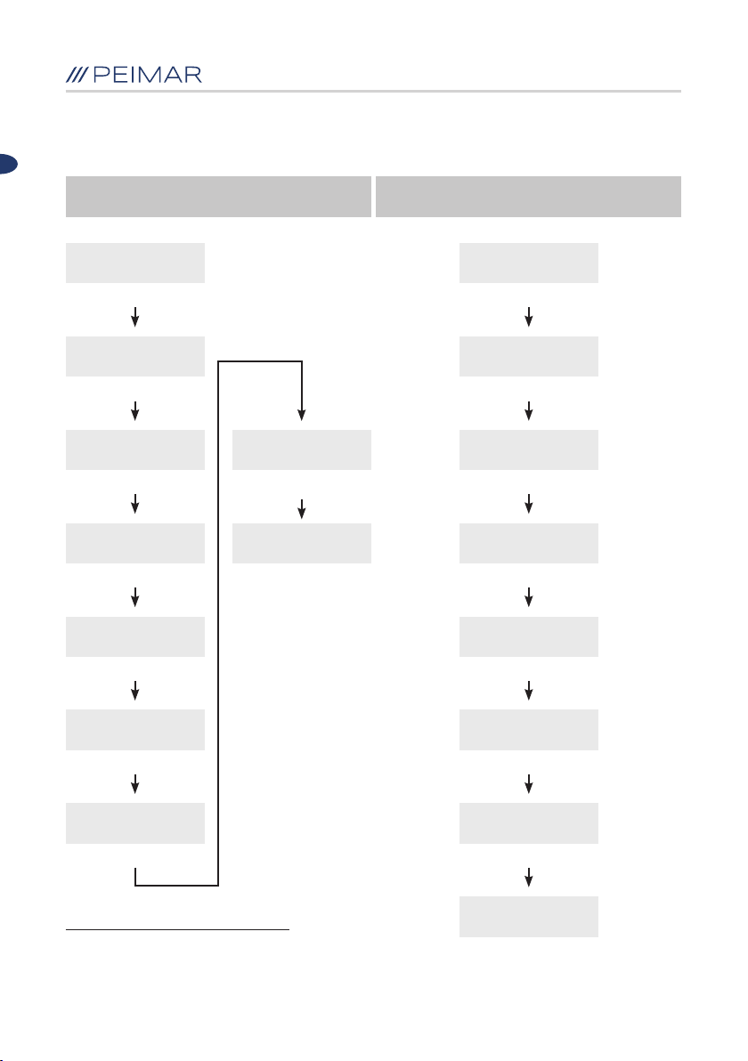
Reset Password Clear Fault Records
EN
E-today 0.00 kWh
P-ac 21 W
ENT
> Running-Info
Statistic-Info
▼
> Set-Param
Inverter-Info
ENT
> Language
Date
▼
> Change Password
Clear Errors
ENT
Please Enter
Password:
******
ENT
Set New Password
AS:
Set Completed!
******
ENT
?
E-today 0.00 kWh
P-ac 21 W
ENT
> Running-Info
Statistic-Info
▼
> Set-Param
Inverter-Info
ENT
> Language
Date
▼
Change Password
> Clear Errors
ENT
Please Enter
Password:
******
ENT
Please Enter New
Password:
Attention default password: “123456”
******
ENT
Are you sure
to set it?
ENT
Set Completed!
92

Clear Energy Factory Setting
EN
E-today 0.00 kWh
P-ac 21 W
ENT
> Running-Info
Statistic-Info
▼
> Set-Param
Inverter-Info
ENT
> Language
Date
▼
> Clear Energy
Factory Setting
ENT
Please Enter
Password:
******
ENT
E-today 0.00 kWh
P-ac 21 W
ENT
> Running-Info
Statistic-Info
▼
> Set-Param
Inverter-Info
ENT
> Language
Date
▼
Clear Energy
> Factory Setting
ENT
Please Enter
Password:
******
ENT
Are you sure
to set it?
ENT
Set Completed!
Inverter restart
automatically
Are you sure
to set it?
ENT
Set Completed!
Attention default password: “123456”
93

6.5 Complete Selftest of the inverter
(Only when the country selected is “Italy 0-21”)
All test command
E-Today 0.00 kWh
P-ac 21 W
ENT
EN
Peripheral
> Selftest
ENT
> 1 Ovp(59.S2)
2 Ovp10(59.S1)
ENT
▼
> 9 All test
ENT
▲
All test [0]
[0] result
▲ ▼
All test [1]
[1] test
ENT
9 All test
Please Wait 2499s
Tests passed!
ENT
All test [0]
[0] result
ENT
1 Ovp(59.S2)
Vt264.5V Tt200ms
ENT
▼
1 Ovp(59.S2)
Vs230.7V To190ms
...........
▼
2018/10/29 08:00
94

6.6 Individual Selftest of the inverter
(Only when the country selected is “Italy 0-21”)
Over-voltage protection test (59.S2)
EN
Over-voltage protection test
of average voltage (59.S1)
> Running-Info
Statistic-Info
▼
Peripheral
> Selftest
ENT
> 1 Ovp(59.S2)
2 Ovp10(59.S1)
ENT
Ovp(59.S2) [0]
[0] result
▲
Ovp(59.S2) [1]
[1] test
ENT ENT
1 Ovp(59.S2)
Please Wait 599s
All test [0]
[0] result
ENT
1 Ovp(59.S2)
Vt264.5V Tt200ms
ENT
Vs230.7V To190ms
Vo230.2V Pass
ENT
2018/10/29 08:00
> Running-Info
Statistic-Info
▼
Peripheral
> Selftest
ENT
1 Ovp(59.S2)
> 2 Ovp10(59.S1)
ENT
Ovp10(59.S1) [0]
[0] result
▲
Ovp10(59.S1) [1]
[1] test
2 Ovp10(59.S1)
Please Wait 599s
Test passed!
ENT
Test passed!
ENT
...........
95

EN
Under-voltage protection test (27.S1)
> Running-Info
Statistic-Info
▼ ▼
Peripheral
> Selftest
ENT ENT
> 3 Uvp(27.S1)
4 Uvp2(27.S2)
ENT ENT
Uvp(27.S1) [0]
[0] result
▲ ▲
Uvp(27.S1) [1]
[1] test
ENT ENT
Secondary under-voltage
protection test (27.S2)
> Running-Info
Statistic-Info
Peripheral
> Selftest
3 Uvp(27.S1)
> 4 Uvp2(27.S2)
Uvp2(27.S2) [0]
[0] result
Uvp2(27.S2) [1]
[1] test
3 Uvp(27.S1)
Please Wait 599s
Test passed! Test passed!
ENT ENT
........... ...........
4 Uvp2(27.S2)
Please Wait 599s
96

EN
Over-frequency protection test (81>. S1)
> Running-Info
Statistic-Info
▼ ▼
Peripheral
> Selftest
ENT ENT
> 5 Ofp(81>.S1)
6 Ofp2(81>.S2)
ENT ENT
Ofp(81>.S1) [0]
[0] result
▲
Ofp(81>.S1) [1]
[1] test
ENT ENT
Secondary over-frequency
protection test (81>. S2)
> Running-Info
Statistic-Info
Peripheral
> Selftest
5 Ofp(81>.S1)
> 6 Ofp2(81>.S2)
Ofp2(81>.S2) [0]
[0] result
ENT
Ofp2(81>.S2) [1]
[1] test
5 Ofp(81>.S1)
Please Wait 599s
Test passed! Test passed!
6 Ofp2(81>.S2)
Please Wait 599s
......................
97
ENTENT

EN
Under-frequency protection test (81 <. S1)
> Running-Info
Statistic-Info
▼ ▼
Peripheral
> Selftest
ENT ENT
> 7 Ufp(81<.S1)
8 Ufp2(81<.S2)
ENT ENT
Ufp(81<.S1) [0]
[0] result
▲ ▲
Ufp(81<.S1) [1]
[1] test
ENT ENT
Secondary under-frequency
protection test (81 <. S2)
> Running-Info
Statistic-Info
Peripheral
> Selftest
7 Ufp(81<.S1)
> 8 Ufp2(81<.S2)
Ufp2(81<.S2) [0]
[0] result
Ufp2(81<.S2) [1]
[1] test
7 Ufp(81<.S1)
Please Wait 599s
Test passed! Test passed!
ENT ENT
........... ...........
8 Ufp2(81<.S2)
Please Wait 599s
98

EN
Note:
1. This setting shall be operated when the inverter is under normal gridconnected state.
2. “All test” is starting from item 1 to item 8 of Selftest.
3. The Selftest results could be reviewed after successful setting.
4. By “All test”, all test results from item 1 to item 8 could be checked all at once.
6.7 Monitoring operation
The equipment is equipped with a RS-232 interface, and the RS-232 interface
can be connected to Wi-Fi module which can be used in the monitoring of the
operation status.
• The equipment can be connected to local internet via a Wi-Fi module and
the Wi-Fi web server which is embedded in the machine; following this, the
operational status of the inverter can be monitored.
• By connecting the Internet through Wi-Fi module and uploading the inverter
data to the server, users can monitor information remotely
99

Chapter 7 - Fault code and troubleshooting
7.1 Fault code and explanation
EN
Error Code 1
Error Code 2
Error Code 3
Error Code 4
Error Code 5
Error Code 6
Error Code 7
Error Code 8
Error Code 9
Error Code 10
Error Code 15
Error Code 18
Error Code 19
Error Code 24
Error Code 27
Error Code 28
Error Code 31
Error Code 33
Error Code 35
Error Code 38
Error Code 39
Error Code 40
Error Code 41
Error Code 50
Error Code 51
Relay Error (Master)
Storer Error (Master)
High Temperature (Master)
Low Temperature Master)
Lost Interior Communication Master)
GFCI Devices Error (Master)
DCI Devices Error (Master)
Current Sensor (Master)
Grid Voltage High (Master)
Grid Voltage Low (Master)
Average voltage of 10 minutes High (Master)
Frequency High (Master)
Frequency Low (Master)
Grid Lost Error (Master)
GFCI Error (Master)
DCI Error (Master)
Insulation Error (Master)
Bus Voltage High (Master)
Current High (Master)
Bus Voltage High Of Hardware (Master)
PV1 Current High of Hardware (Master)
PV2 Current High of Hardware (Master)
Current High of Hardware of Grid (Master)
Lost interior communication (Slave)
Data Consistency of Voltage Error (Slave)
100
 Loading...