

Peha Elektro GmbH & Co. KG
Hunde tragen während
Rolltreppenbenutzung
Hupen Hupen geboten
-2.Vorschlag-
ImpulslichtbogenschweißenImputz-Installationsdose Inert-Gas-Einrichrung
Postfach 1727 • D-58467 Lüdenscheid • Tel.: +49 (0)2351 185-0 • Fax: +49 (0)2351 27666 • e-mail: peha@peha.de • Internet: www.peha.de
Installation and operating instructions
Easyclick 24V JR-receiver Plus
Art.no.: 452/24 FU-EP JR o.T.
GB
1. General
1.1 Application
A roller shutter, blinds or an awning with end position
switch (24V DC motor) can be actuated with the 1 and
2 output of the receiver. The receiver is operated with
Easyclick transmitters (radio signal).
Before use, the transmitters must be assigned to the receiver (max. 32 receivers). Every transmitter can control an
unlimited number of receivers.
Note: Read through the operating instructions carefully
before putting the device into service.
1.2 Warranty conditions
These operating instructions are an integral part of both the
device and our terms of warranty. They must be handed
over to the user. The technical design of the appliance is
subject to change without prior notification. PEHA products
are manufactured and quality-checked with the latest technology according to applicable national and international
regulations. Nevertheless, if a product should exhibit a defect, PEHA warrants to make remedy as follows (regardless of any claims against the dealer to which the end-user
may be entitled as a result of the sales transaction):
In the event of a justified and properly-established claim,
PEHA shall exercise its prerogative to either repair or replace the defective device. Further claims or liability for
consequential damage are explicitly excluded. A justifiable
deficiency is one in which the device exhibits a structural,
manufacturing, or material defect that makes it unusable or
substantially impairs its utility at the time it is turned over to
the end-user. The warranty does not apply to natural wear,
unintended usage, incorrect connection, device tampering
or the effects of external influences. The warranty period is
for 24 months from the date of purchase by the end-user
from a dealer and ends not later than 36 months after the
device’s date of manufacture. German law shall be applicable for the settlement of warranty claims.
1.3 Disposal of the device
The device must be disposed of in compliance with the
laws and standards of the country in which it is operated!
2. Safety
This device is only intended to be used for its stated application. Unauthorised conversions, modifications or changes
are not permissible! This device may not be used in conjunction with other devices whose operation could present a
hazard to persons, animals or property.
The following must be observed:
• Prevailing statutes, standards and regulations.
• State-of-the-art technology at the time of installation.
• The device’s operating instructions.
• Operating instructions can only cite general stipulations.
These are to be viewed in the context of a specific system.
3. Technical specifications
Transmit frequency 868,3 MHz
Power supply 24V DC
Capacity 1A (24V DC)
Ambient temperature
Storage temperature - 40 to + 85°C
Test specifications EN 60669-2-1
Identification CE
Protection type IP20
- 20 to + 40°C
4. Installation
Installation information!
Installation and commissioning may only be done by an
authorised electrician. Mains power 24V DC to electrical
equipment must be switched off during installation. Applicable laws and standards of the country in which the
device is operated must be observed!
• Do not use outdoors (indoor use only).
• Installation close to floor level is not recommended.
• Connect only one motor to the receiver!
•
The direction of rotation of the motor can be changed
over without transit time! A motor which permits direct
changeover of the direction of rotation is to be used.
• The 1 and 2 outputs of the receiver are interlocked.
• Only the receiver, to which the transmitter is to be
assigned, should be in learn mode! If another receiver
is in learn mode, it is possible that the transmitter may
be inadvertently assigned to this receiver or deleted!
• Refer to the operating instructions for the
Easyclick transmitter!
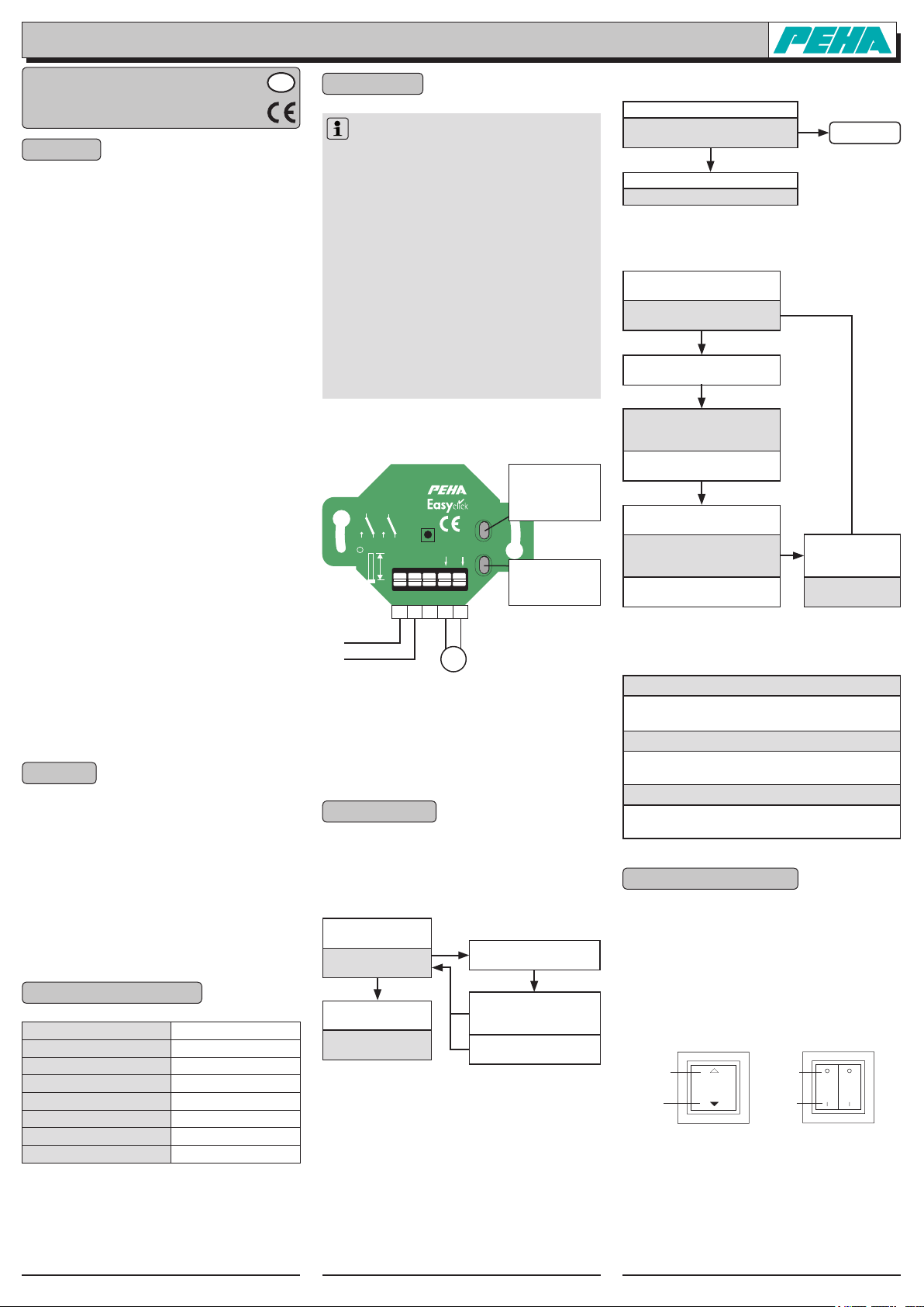
This device is intended for installation in a flush-mount
installation box. They are to be equipped with the 1 - 5
multipurpose frame from the PEHA switch range.
CLR / MODE button
with LED
Delete all transmitters and para-
CLR/MODE
meter setting
LRN/SET
LRN / SET button
with LED
Learn mode and function programming.
Learn mode:
LED = red
Function programming:
LED = green or orange
+
–
µ
+-+
I max.1A
M
N
external
24V DC
GND
452/24 FU-EP JR o.T.
µ
-
24VDC
+
+ –
1
—
1 2
9 mm
2
M
• Install flush-mounted installation box in a suitable position.
• Install connection cables.
• Insert the device into the flush-mount installation box
and screw-fasten it securely in place.
• Switch on power supply after installation.
• Program the receiver (see Point 5).
5. Programming
For programming, the receivers must be connected to the
mains power supply. The programming is retained even in
a power failure.
5.1 Learn mode (assigning or deleting transmitters)
LRN/SET button
press briefly
Learn mode
(LED blinks red)
LRN/SET button
press briefly
Idle state
(LED off)
Notes:
– No transmitter is assigned to the receiver in its
delivered state.
– Several transmitters can be assigned (max. 32 receivers)
or deleted in learn mode.
– A transmitter is alternately assigned (LED on) or deleted
(LED off) each time the button is pressed!
– The receiver‘s Function 1 is preset after assigning a
transmitter to the receiver. The function can be changed
for every transmitter (see point 5.3).
– If no action takes place, learn mode will be terminated
after 30 s.
Activate transmitter once
(e.g. press button)
Transmitter assigned
(LED 1 on)
Receiver = Function 1
Transmitter deleted
(LED off)
5.2 Deleting all assigned transmitters
CLR/MODE button long activation
All transmitters deleted
Learn mode (LED blinks red)
s. Point 5.1
LRN/SET button press briefly
Idle state (LED off)
5.3 Function programming
LRN/SET button
long activation
Function programming
(LEDs blinks green rapidly)
Transmitter detection
(
Activate transmitter once
)
Function setting
(LED blinks orange
number of blinks = function)
Press LRN/SET button
(number = function selection)
CLR/MODE
button
press briefly
Parameter setting
(LED blinks green
number of blinks = parameter)
Press LRN/SET button
(number = parameter selection)
CLR/MODE
button
press briefly
Idle state
(LED off)
Note: If no action takes place, function programming will
be terminated after 30 s.
Transmitter detection (e.g. press transmitter button)
Activate transmitter once
LED blinks orange
transmitter detected
Function setting (e.g. function 3)
LRN/SET button 3 x activated
LED blinks 3 x orange function 3
Parameter setting (e.g. parameter 2)
LRN/SET button 2 x activated
LED blinks 2 x green parameter 2
6. Operation and functions
6.1 Operating
The receiver is operated with Easyclick transmitters (radio
signal). Before use, the transmitters must be assigned to
the receiver (max. 32 receivers). The receiver‘s Function 1
is preset after assigning a transmitter to the receiver. It can
be changed by function programming. Every transmitter
can control an unlimited number of receivers.
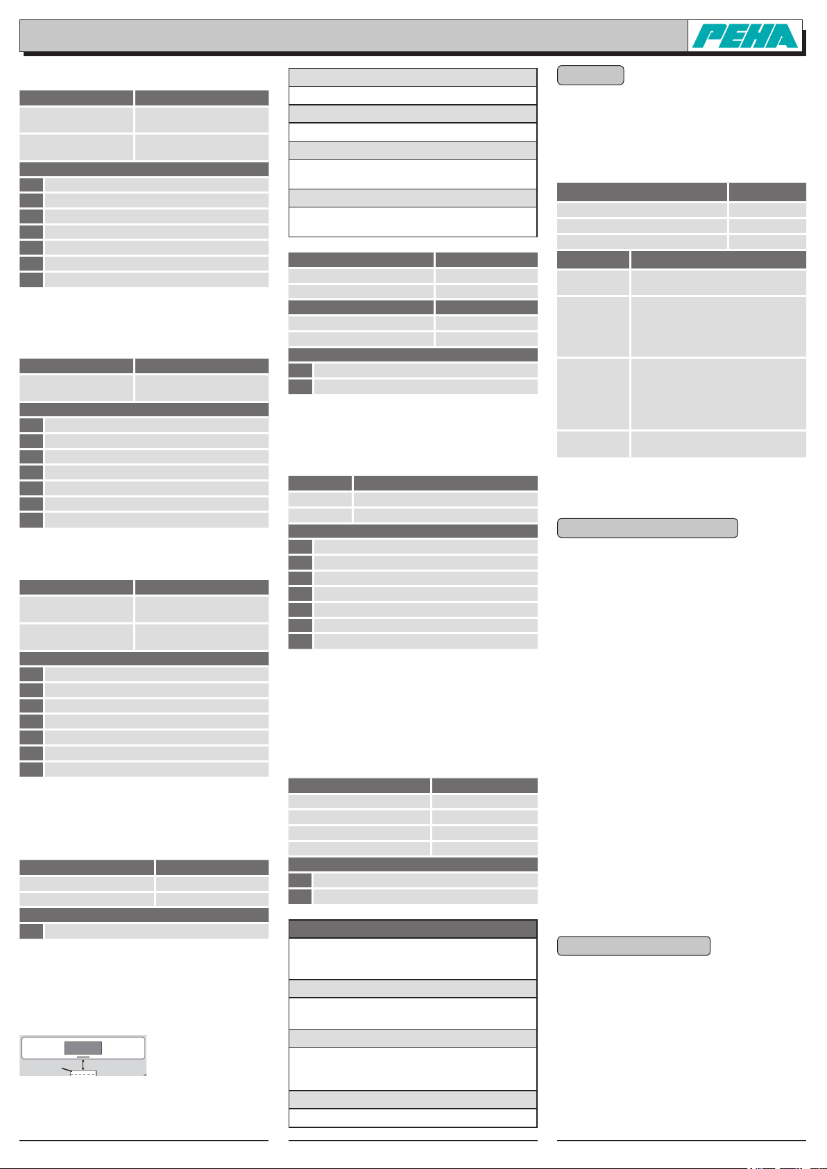
6.2 Easyclick wall transmitters
Button UP
Button
DOWN
Button O
Button I
GB - 1452-24 FU EP JR o.T. (Rev01_110112) 126471-01
Peha Elektro GmbH & Co. KG
Postfach 1727 • D-58467 Lüdenscheid • Tel.: +49 (0)2351 185-0 • Fax: +49 (0)2351 27666 • e-mail: peha@peha.de • Internet: www.peha.de
6.2.1 Function 1 (Two-button operation)
Wall transmitter Function
Press button UP or
DOWN briefly
Press button UP or
DOWN long
Parameters
1 120 sec running time
2 10 sec running time
3 30 sec running time
4 60 sec running time
5 5 min running time
6 10 min running time
7 60 min running time
Note: Standard function after assigning a transmitter!
6.2.2 Function 2 (One-button operation)
Wall transmitter Function
Press button UP
or DOWN
Parameters
1 120 sec running time
2 10 sec running time
3 30 sec running time
4 60 sec running time
5 5 min running time
6 10 min running time
7 60 min running time
6.2.3 Function 3 (Button control)
Wall transmitter Function
Press button UP
or DOWN
Release button UP
or DOWN
Parameters
1 120 sec running time
2 10 sec running time
3 30 sec running time
4 60 sec running time
5 5 min running time
6 10 min running time
7 60 min running time
6.2.4 Function 4 (Automatic mode)
Already integrated for future applications! Activating automatic mode opens up options for using the receiver in
combination with a sun sensor (Point 6.2.6) .
Wall transmitter Function
Press button DOWN or I
Press button UP or O
Parameters
1 Sun mode
6.2.5 Function 5 (Interlock)
The locking of roller shutters / blinds serves f.ex. the security during maintenance work. An activation of the lock is
carried out through a wall transmitter or through a window
contact when the terrace door is open.
Magnet
max. 5mm
UP, DOWN or STOP (blade
adjustment for blinds)
Continuous operation
UP / DOWN (parameter)
Continuous operation
UP / DOWN (parameter)
UP or DOWN (blade adjustment for blinds)
STOP
Automatic mode on
Automatic mode off
PEHA window contact
(450 FU FK)
Learn mode
Assign / delete window contact with its program button.
Function programming (transmitter detection)
Activate the window contact once with the magnet.
Function setting (e.g. function 5)
LRN/SET button 5 x activated
LED blinks 5 x orange function 5
Parameter setting (e.g. parameter 2)
LRN/SET button 2 x activated
LED blinks 2 x green parameter 2
Wall transmitter Function
Press button DOWN or I
Press button UP or O
Window contact Function
Opened Interlock
Closed Unlocking
Parameters
1 Wall transmitter safety function
2 Window contact safety function
6.2.6 Function 6 (Sun sensor)
Already integrated for future applications! Switch on automatic mode (see Point 6.2.4).
Sun sensor Function
On signal DOWN (1 s blade adjustment for blinds)
Off signal UP
Parameters
1 10 sec running time
2 13 sec running time
3 16 sec running time
4 20 sec running time
5 25 sec running time
6 30 sec running time
7 40 sec running time
Notes:
– Please follow the sun sensor’s instructions.
– The „UP“ function during the „OFF“ signal of the sun
sensors is especially recommendable for sunblinds!
6.2.7 Function 7 (Scenes)
With this function, set positions of the roller shutters /
blinds (scenes) can be stored and called up again.
Wall transmitter Function (parameter)
Press button / O briey
Press button / O long
Press button / I briey
Press button / I long
Parameter
1
button / O = scene A, button / I = scene B
2
button / O = scene C, button / I = scene D
Application example: scene
A scene can be adjusted by using a transmitter and an
available control (various receivers with assigned transmitters).
Programming
Assign the transmitter to each receiver, program function 7 and set parameter.
Store scene (A-D)
• Set required positions of roller shutters/blinds.
• Press button/I or /O of the transmitter
for longer than 2s.
Select scene (A-D)
Press briefly the button /I or /O of the transmitter.
UP and interlock
Unlocking
Switch on scene A/C
Store light A/C
Switch on scene B/D
Store light B/D
7. Range
The strength of the radio signal between the transmitter
and switching receiver weakens as distance increases.
The range can be further reduced by different materials
or interference sources in the propagation direction of the
radio waves. The range can be increased by the use of
Easyclick Repeaters (radio amplifiers).
Material Reduction
Wood, plaster, non-coated glass 0 - 10%
Masonry, wood/plaster walls 5 - 35%
Reinforced concrete 10 - 90%
Range Conditions
> 30 m
> 20 m
> 10 m
Through 1-2
ceiling / wall
Note:
Go to www.peha.de for further information on “Range”.
Under good conditions (large, clear
space without obstructions).
Through up to 5 plaster/drywall board
walls or 2 brick/porous concrete walls
(furniture and persons in the room):
For transmitter and receiver with good
aerial positioning/layout.
Through up to 5 plaster/drywall board
walls or 2 brick/porous concrete walls
(furniture and persons in the room):
For receivers installed in walls or corners of rooms, receivers with internal
aerial or narrow corridors.
Depending on ceiling/wall armouring
and type of aerial in the receiver.
8. Troubleshooting & remedies
8.1 New system or existing system
• Check power supply (electrician only).
• Check connected electrical loads.
• Check the system’s surroundings for changes that could
cause interference (e.g. metal cabinets, furniture or walls
which have been moved).
• If the transmitter/receiver operates at a reduced distance,
the radio signal was encountering interference or it was
operating outside the transmission range.
• Use the receiver at a better location.
• Delete all transmitters and reprogram the receiver.
8.2 Receiver switches by itself
• This may be caused by operation of an external trans mitter that was coincidentally assigned to the receiver.
• Delete all transmitters and reprogram the receiver.
8.3 Radio signal range limitations
• Use of the receiver in the vicinity of metal objects or
materials with metal components.
Maintain a distance of at least 10 cm.
• Moist materials.
• Devices which emit high-frequency signals (e.g. audio
and video systems, computers, electronic ballasts in
light xtures). Maintain a distance of at least 0.5 m.
8.4 Contact
Telephone:................ +49 (0)2351 185-0
Fax:.......................... +49 (0)2351 27666
Internet:.................... www.peha.de
E-mail:...................... peha@peha.de
9. Conformity declaration
PEHA products may be sold and operated in EU countries
as well as in CH, IS and N. PEHA herewith declares that
the receiver (452/24 FU-EP JR o.T.) is in compliance with
the fundamental requirements and other relevant provisions of R&TTE Directive 1999/5/EC.
The conformity declaration is available on the Internet at
the following address: www.peha.de
GB - 2452-24 FU EP JR o.T. (Rev01_110112) 126471-01
 Loading...