


Use and maintenance manual
ELECTRICAL BOARDS FOR REFRIGERATING INSTALLATIONS
READ AND KEEP
REV. 02-18
ENG
VISION SC600
ENGLISH
Rel. Software: 8

VISION SC600
Rev. 02-18
USE AND MAINTENANCE MANUAL
REV. 01/04
Pag. 2

VISION SC600
Rev. 02-18
USE AND MAINTENANCE MANUAL
TABLE OF CONTENTS
CHAP. 1
CHAP. 2
CHAP. 3
CHAP. 4
CHAP. 5
CHAP. 7
CHAP. 6
INTRODUCTION
Pag. 4 1.1 Generality
Pag. 5 1.2 Product identification codes
Pag. 5 1.3 Overall clearances
Pag. 5 1.4 Identification data
INSTALLATION
Pag. 6 2.1 Main warnings for the installer
Pag. 6 2.2 Standard equipment for assembly and use
Pag. 7 2.3 Board installation
FUNCTIONALITY
Pag. 8 3.1 Functions managed by VISION SC600
TECHNICAL FEATURES
Pag. 9 4.1. Technical features
Pag. 10 4.2 Warranty conditions
DATA PROGRAMMING
Pag. 11 5.1 Control panel
Pag. 11 5.2 Front keyboard
Pag. 12 5.3 Keys combination
Pag. 13 5.4 LCD Display
Pag. 14 5.5 Generality
Pag. 15 5.6 Symbols
Pag. 15 5.7 Setpoint setting and displaying
Pag. 15 5.8 First level programming
Pag: 16 5.9 List of first level programming variables
Pag. 18 5.10 Second level programming
Pag. 18 5.11 List of second level programming variables
Pag. 21 5.12 Third level programming
Pag. 21 5.13 List of third level programming variables
Pag. 23 5.14 Sequence and activation delays
Pag. 25 5.15 Input and output configuration
Pag. 26 5.16 Operating mode – inverter management
Pag. 36 5.17 Operating mode – compressors capacity management
OPTIONS
Pag. 39 6.1 Supervision/monitoring system TeleNET
DIAGNOSTIC
Pag. 40 7.1 Diagnostic
Pag. 43 7.2 Alarm history management
ATTACHMENTS
Pag. 44 A.1 EU Declaration of conformity
Pag. 45 A.2 Connection to 100N MASTER 3
Pag. 3

VISION SC600
Rev. 02-18
USE AND MAINTENANCE MANUAL
CHAPTER 1: INTRODUCTION
CHAP. 1 - Introduction
GENERALITY
The VISION SC600 system allows users to control the machine room of a refrigeration
plant in which there is more than one compressor. It guarantees uniform operation and
proper distribution of operating times among individual machines. All functions are
performed in complete safety and the VISION SC600 Control Console (LCD DISPLAY)
can be installed anywhere, independently of where the power cabinet is located.
APPLICATIONS:
- Compressor and condenser fan control of a refrigeration plant
MAIN FEATURES:
- Configurable for control of compressors (up to a maximum of 10) and condenser fans
(up to a maximum of 10). It’s possible to configure the outputs by setting the number of
compressors and fans to control, so that their sum is less than or equal to 10.
- Configurable for compressor partition valves control.
- 0-10V Analog output for compressor inverter control.
- 0-10V Analog output for the adjustment of fan speed in alternative to digital outputs
control of the condenser fans.
- Display of the pressure probe measure in Bar or in °C (conversion based on the type of
refrigerant gas selected).
- Rotation of compressors / fans according to the time of operation.
- Management compressors of different or the same powers.
- Side band regulation.
- Night / day management (energy saving).
- Back-lit LCD display.
- Clock and calendar.
- Password for keys lock.
- RS485 Serial connection (Modbus-RTU or Telenet protocol).
- Pego programming philosophy that guarantees an immediate start-up.
Pag. 4

VISION SC600
Rev. 02-18
USE AND MAINTENANCE MANUAL
CAP. 1 - Introduction
100N MASTER3 SC600
VISION SC600
PRODUCT IDENTIFICATION CODES
VISION SC600 Compressor and condenser fan control
of a refrigeration plant.
OVERALL CLEARANCES
Dimensions in mm:
IDENTIFICATION DATA
The equipment described in this manual is provided with an identification data plate of the
same placed on one side:
• Name of Manufacturer
• Equipment code
• Serial number
• Power supply voltage
Pag. 5

VISION SC600
Rev. 02-18
USE AND MAINTENANCE MANUAL
CHAPTER 2: INSTALLATION
CAP. 2 - Installation
MAIN WARNINGS FOR THE INSTALLER
1. Install the equipment in places complying with the protection degree and keep the box
as intact as possible when making holes to house the cable glands and/or conduit
glands.
2. Avoid using multicore cables with conductors connected to inductive and power loads
and signal conductors which probes and digital inputs.
3. Avoid housing power supply cables with signal cables (probes and digital inputs) in the
same conduit.
4. Reduce the lengths of the connection cables as much as possible, avoiding the wiring
assuming the spiral shape, damaging for possible inductive effects on the electronics.
5. All conductors used in the wiring must be suitably proportioned to support the load to be
powered.
6. Provide a main protection fuse upstream of the electronic control.
7. If required to extend the probes, use conductors with suitable section and not below
1mm². The extending or shortening of the probes may alter the factory calibration; use
an external thermometer to check and calibrate.
STANDARD EQUIPMENT FOR ASSEMBLY AND USE
For assembly and use, the electronic controller VISION SC600, is equipped with:
• Nr 1 telephone plug cable;
• Nr 1 use manual;
• Nr 1 console VISION SC600 (200VISIONSC600);
• Nr 1 100N MASTER3 (200100NMSTH3);
Pag. 6

VISION SC600
Rev. 02-18
USE AND MAINTENANCE MANUAL
CAP. 2 - Installation
INSTALLATION
Fig. 1: Position the module 100N
MASTER3 on the DIN guide and
close the 2 lower hooks to lock it
on the same.
Fig. 2: Fix the VISION SC600 console
using the two screws to be
inserted in the slots underneath
the keys frame.
Fig. 3: VISION SC600 console
perforation template.
Pag. 7

VISION SC600
Rev. 02-18
USE AND MAINTENANCE MANUAL
CAP. 3 - Functionality
CHAPTER 3: FUNCTIONALITY
FUNCTIONS MANAGED BY VISION SC600
- Compressor control of a refrigeration plant, up to a maximum of 10.
- Condenser fan control of a refrigeration plant, up to a maximum of 10.
- It’s possible to configure the outputs by setting the number of compressors and fans to
control, so that their sum is less than or equal to 10.
- Compressor partition valves control. Each compressor output is associated to another
output to control the corresponding partition valve (NC or NO).
- Sideband compressors and fans regulation.
- Analog output 0-10V for compressor inverter management. Compressor relay outputs
are still controlled.
- 0-10V Analog output for the adjustment of fan speed in alternative to digital outputs
control of the condenser fans.
- Rotation of compressors / fans according to the time of operation.
- Management compressors of different or the same powers.
- Clock and calendar.
- RS485 Serial connection (Modbus-RTU or Telenet protocol).
- Alarm history management. You can view the last highest priority alarm occurred, or
the list of the last 40 alarms with their time or date of activation.
- Alarm relay.
- Remote Stand-by digital input.
- Night / day management (energy saving).
Pag. 8

VISION SC600
Rev. 02-18
USE AND MAINTENANCE MANUAL
Power supply
Voltage
230 V~ 10% 50/60Hz
Max. absorbed power (electronic control only)
~ 8 VA
Climatic Conditions
Work temperature
-5 ÷ +50 °C
Storage temperature
-10 ÷ +70 °C
Ambient relative humidity
Below 90% Hr
Main Features
Type of connectable probes (pressure)
4 – 20mA
Output features
Description
Installed relay
Board output features
Notes
OUT 1 (output 3-4)
(Relay 30A AC1)
30A 240V~ (AC1)
10A 240V~ (AC3) (2HP)
(100000 cycles)
All outputs
are clean contacts
without voltage
Nr 9 outputs from 5 to 26
(Relay 16A AC1)
16A 240V~ (AC1)
3A 240V~ (AC3)
Dimensional features
100N MASTER 3 Dimensions
121.50mm x 71mm x 175mm (HxDxL)
VISION SC 600 Dimensions (fitted)
70mm x 32mm x 158mm (HxDxL)
Mechanical and insulation features
Display protection degree
IP65
Box material
Self-extinguishing ABS
CAP. 4 - Technical features
CHAPTER 4: TECHNICAL FEATURES
TECHNICAL FEATURES
Pag. 9

VISION SC600
Rev. 02-18
USE AND MAINTENANCE MANUAL
CAP. 4 - Technical features
WARRANTY CONDITIONS
The VISION SC600 series products are covered by a 24-months warranty against all
manufacturing defects as from the date indicated on the product ID code.
In case of defect the product must be appropriately packaged and sent to our production
plant or to any authorized Service Center with the prior request of the Return Authorization
Number.
Customers are entitled to have defective products repaired, spare parts and labour
included. The costs and the risks of transport are at the total charge of the Customer.
Any warranty action does not extend or renew its expiration.
The Warranty does not cover:
Damages resulting from tampering, impact or improper installation of the product and
its accessories.
Installation, use or maintenance that does not comply with the instructions provided
with the product.
Repair work carried out by unauthorized personnel.
Damage due to natural phenomena such as lightning, natural disasters, etc…
In all these cases the costs for repair will be charged to the customer.
The intervention service in warranty can be refused when the equipment is modified or
transformed.
Under no circumstances Pego S.r.l. will be liable for any loss of data and information,
costs of goods or substitute services, damage to property, people or animals, loss of sales
or earnings, business interruption, any direct, indirect, incidental, consequential,
damaging, punitive, special or consequential damages, in any way whatsoever caused,
whether they are contractual, extra contractual or due to negligence or other liability arising
from the use of the product or its installation.
Malfunction caused by tampering, bumps, and inadequate installation automatically
declines the warranty. It is compulsory to observe all the instructions in this manual and
the operating conditions of the product.
Pego S.r.l. disclaims any liability for possible inaccuracies contained in this manual if due
to errors in printing or transcription.
Pego S.r.l. reserves the right to make changes to its products which it deems necessary
or useful without affecting its essential characteristics.
Each new release of the Pego product user manual replaces all the previous ones.
As far as not expressly indicated, is applicable the Law and in particular the art. 1512 C.C.
(Italian Civil Code).
For any controversy is elected and recognized by the parties the jurisdiction of the Court of
Rovigo.
Pag. 10

VISION SC600
Rev. 02-18
USE AND MAINTENANCE MANUAL
FANS SET
Allows you to set the fans set point when pressed in combination with
the Up or Down button. Reset the alarm sound if any.
COMPRESSORS SET
Allows you to set the compressors set point when pressed in
combination with the Up or Down button. Restore the alarm sound if
any.
STAND BY (plant ON/OFF)
DOWN
Decreases the values / Scroll down the parameters
CHAP. 5 - Data programming
CHAPTER 5: DATA PROGRAMMING
State led
CONTROL PANEL
FRONT KEYBOARD
Pag. 11

VISION SC600
Rev. 02-18
USE AND MAINTENANCE MANUAL
MUTE ALARM
Reset sound alarm if any. If pressed more than 3 seconds displays the
alarm history.
UP
Increases the values / Scroll up the parameters
+
EXIT PROGRAMMING
If pressed simultaneously for more than 3 seconds within
any programming menu or the historical alarm allow you
to exit the menu.
Exit from menu generates a confirmation beep.
+
1st LEVEL PROGRAMMING
If pressed simultaneously for more than 3 seconds allow
access to the first level programming menu (if you are not
in programming). Exit from this menu takes place
automatically after 30 seconds of keyboard inactivity or
by pressing up arrow + down arrow (confirmation beep
output).
+ +
2nd LEVEL PROGRAMMING
If pressed simultaneously for more than 3 seconds allow
access to the second level programming menu.
At the entrance of the menu a confirmation beep is
generated.
+ +
+
3rd LEVEL PROGRAMMING
If pressed simultaneously for more than 3 seconds allow
access to the third level programming menu.
At the entrance of the menu a confirmation beep is
generated.
+
OUTPUT HOUR COUNTER / ALARM HISTORY RESET
While viewing the working time of an output within the
read-only Hr1, Hr2, Hr3, Hr4, Hr5, Hr6, Hr7, Hr8, Hr9,
Hr0 parameters while pressing the SET_COMP key and
pressing the "SET_VENT" for at least 10 seconds, the
hour counter will be reset.
Similarly while viewing the alarm history while pressing
the SET_COMP key and pressing the "SET_VENT" for at
least 10 seconds, the alarm history will be reset.
CHAP. 5 - Data programming
KEYS COMBINATIONS
Pag. 12

VISION SC600
Rev. 02-18
USE AND MAINTENANCE MANUAL
+
SWITCHING FROM Bar to °C
While viewing several variables in Bar, pressing the
stand-by key and Set together switches the view from
Bar to °C according to the table of the gas type selected
until the keys are released.
The variables involved with this kind of view are:
- Setpoint compressors, r0C, LSC, HSC.
- Setpoint fans, r0V, LSU, HSU.
1.
Intake sensor reading (low pressure) / parameters
At night operation decimal point flashes.
2.
Delivery sensor reading (high pressure) / parameters values /
Error code
3.
Time / time parameters value
4.
PRG
Programming mode (the control is in the programming phase)
5.
Compressors call (compressor call signaling)
6.
Fans call (fans call signaling)
7.
Alarm
CHAP. 5 - Data programming
LCD DISPLAY
Pag. 13

VISION SC600
Rev. 02-18
USE AND MAINTENANCE MANUAL
8.
Stand-by (flashing in stand-by. Outputs are disabled)
9.
Outputs status display
(compressors – compressors capacity – fans).
(flashing if waiting t1c/u, t2 c/u, t3 c/u, t4 c/u time)
Each output is displayed with a couple of squares to indicate whether the
output X is in "Compressor ON", "Fan ON" or "Compressor partition-ON".
During configuration, the compressors are always associated to the first exit,
then there are partitions and finally the fans (left to right).
LOW
PRESS.
Intake sensor reading (low pressure) in Bar.
TEMP.
°C
Intake sensor reading (low pressure) in °C.
HIGH
PRESS.
On = delivery sensor reading (high pressure) in Bar.
HIGH
PRESS
Off = delivery sensor reading (high pressure) in °C.
CHAP. 5 - Data programming
Fan X ON
Compressor partition X ON
Compressor X ON
GENERALITY
For the operator’s safety and practicality, VISION SC600 system envisions three
programming levels; the first for configuration of the frequently amendable SET POINT
parameters only, the second for programming and setting the main parameters relating to
the various board functioning modes, and the third for programming input/output of the
board. It is not possible to directly access the second or third level from the first level
programming, exit current programming first.
Pag. 14

VISION SC600
Rev. 02-18
USE AND MAINTENANCE MANUAL
CHAP. 5 - Data programming
SYMBOLS
For practicality we will use the following symbols:
• () the UP key that performs value increase functions;
• () the DOWN key that performs value decrease functions.
SET POINT SETTING AND DISPLAYING
1. Press the SET COMPRESSOR key to display the current SET POINT in Bar.
2. Keeping the SET COMPRESSORI key pressed and pressing one of the () o ()
keys, the SET POINT value can be amended. Release the SET key to return to
displaying the regulation probe value; memorising of the made amendments will
automatically happen.
NOTE: Similarly for the setting of the setpoint related to fans repeat the above steps using
the SET FANS key instead of the SET COMPRESSORS key. While viewing the SET
POINT value in Bar (SET button pressed), if you press the standby key at the same time,
you will view the value changed to °C depending on the type of Gas set. While viewing the
value in °C, it will not be possible to change the set through the arrows.
FIRST LEVEL PROGRAMMING (User level)
To access the first level configuration:
1. Keep the keys () and () pressed simultaneously for a few seconds until the first
programming variable appears on the display.
2. Release the keys () and ().
3. Using the () key or () key, select the variable to be amended.
4. After having selected the wanted variable, it will be possible to amend its setting by
keeping the SET COMPR (or SET FANS) key pressed and by pressing one of the () or
() keys.
To exit the menu once the configuration values are set, simultaneously keep the () and
() keys pressed for a few seconds, until the pressure measure value appears again.
5. Memorisation of the amendments made to the variables will happen automatically when
exiting the configuration menu.
Pag. 15
VISION SC600
Rev. 02-18
USE AND MAINTENANCE MANUAL
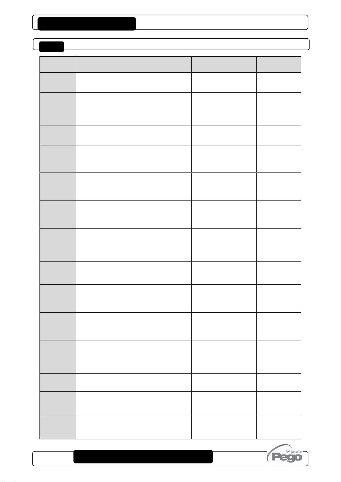
LABEL
MEANING
VALUES
DEFAULT
r0C
SET differential (of the pressure)
compressors (interlocked with nC)
0.2 30 bar
Step 0.2 Bar
0,6
t1C
The minimum time that must elapse
between the insertion of a compressor
step and the next one (SECONDS)
This time avoids breakaways caused
by simultaneous start-ups.
2 500
step 2 sec
20
t2C
The minimum time that must elapse
between two different compressor
step deactivations. (SECONDS)
2 500
step 2 sec
10
t3C
The minimum time that must elapse
between two successive insertions
of the same compressor step.
(SECONDS)
2 500
step 2 sec
320
t4C
The minimum time that must elapse
between one shutdown and the next
insertion of the same compressor
step. (SECONDS)
2 500
step 2 sec
2
r0U
SET differential (of the pressure) fans.
(interlocked with iOu but only if iEn=2 or
iEn=3, otherwise interlocked with nU)
0.6 5 bar
Step 0.2 Bar
2,0
t1U
The minimum time that must elapse
between the insertion of a fan step and
the next one. (SECONDS)
This time avoids breakaways caused
by simultaneous start-ups.
2 500
step 2 sec
2
t2U
The minimum time that must elapse
between two different fan step
deactivations. (SECONDS)
2 500
step 2 sec
2
t3U
The minimum time that must elapse
between two successive insertions
of the same fan step. (SECONDS)
2 500
step 2 sec
10
t4U
The minimum time that must elapse
between one shutdown and the next
insertion of the same fan step.
(SECONDS)
2 500
step 2 sec
2
Fty
Type of refrigerant GAS in use.
The wrong configuration of this
parameter does not affect operation.
0 = 404 4 = 410
1 = 134 5 = 507
2 = R22 6=CO2
3 = 407 7=R407F
1
UM
View unit of measurement
0 = °C 1 = Bar
1
AOC
Display of the 0-10V analogue output
for compressor inverter
0,0 – 10,0V
with iEn=0 or 2
displays - - -
Read only
AOU
Display of the 0-10V analogue output
for condenser fans inverter
0,0 – 10,0V
with iEn=0 or 1
displays - - -
Read only
CHAP. 5 - Data programming
FIRST LEVEL VARIABLES LIST (User Level)
Pag. 16

VISION SC600
Rev. 02-18
USE AND MAINTENANCE MANUAL
ALL
View of the last alarm triggered
Alarm code
Read only
A1C
Minimum compressor pressure alarm
The absolute pressure referring to the
Intake probe below which, once the Ald
delay time is activated, the LOW pressure
alarm is triggered showing ELc alternating
with the pressure on the display and the
flashing of the alarm icon.
When the alarm turns off, the "alarm
presence" icon will remain lit to indicate
which operation has occurred until the
alarm button is pressed.
-0,6 ÷ (A2C-0,2)
Bar, step 0,2 Bar
-0,6 bar
A2C
Maximum compressor pressure alarm
The absolute pressure referring to the
Intake probe above which, once the Ald
delay time is activated, the HIGH pressure
alarm is triggered showing EHc alternating
with the pressure on the display and the
flashing of the alarm icon.
When the alarm turns off, the "alarm
presence" icon will remain lit to indicate
which operation has occurred until the
alarm button is pressed.
(A1C+0,2) ÷ +30,0
Bar, step 0,2 Bar
+30,0 bar
A1U
Minimum fan pressure alarm
The absolute pressure referring to the
delivery probe below which, once the Ald
delay time is activated, the LOW pressure
alarm is triggered showing ELu alternating
with the pressure on the display and the
flashing of the alarm icon.
When the alarm turns off, the "alarm
presence" icon will remain lit to indicate
which operation has occurred until the
alarm button is pressed.
-0,6 ÷ (A2U-0,2)
Bar, step 0,2 Bar
-0,6 bar
A2U
Maximum fan pressure alarm
The absolute pressure referring to the
delivery probe above which, once the Ald
delay time is activated, the HIGH pressure
alarm is triggered showing EHu alternating
with the pressure on the display and the
flashing of the alarm icon.
When the alarm turns off, the "alarm
presence" icon will remain lit to indicate
which operation has occurred until the
alarm button is pressed.
(A1U+0,2) ÷ +30,0
Bar, step 0,2 Bar
+30,0 bar
tdS
Day start time programming (ignored if
dnE=0 or there is a night digital input)
00:00 ÷ 23:59
06:00
tdE
Day end time programming (ignored if
dnE=0 or there is a night digital input)
00:00 ÷ 23:59
22:00
CHAP. 5 - Data programming
Pag. 17

VISION SC600
Rev. 02-18
USE AND MAINTENANCE MANUAL
LABEL
MEANING
VALUES
DEFAULT
SEq
Logical selection of the digital outputs
activation
0 = With rotation
1 = Without rotation
1
Man
Max. number (hours x 10) of operating
hours for a compressor after which a
request for maintenance will be signaled.
(if = 0, the request for maintenance will not
be signaled)
0 ÷ 510
step 2
300
rA
Setting general alarm output
1 = alarm relay(17-18) energized
in alarm.
0 = alarm relay (17-18) disabled.
-1 = alarm relay (17-18)
de-energized when in alarm.
1
PU4
Pressure (bar) corresponding to 4mA
Referred to the high pressure probe.
-1,0 ÷ (PV2 - 0,1)
0,0
PU2
Pressure (bar) corresponding to 20mA
Referred to the high pressure probe.
(PV4 + 0,1) ÷ 50,0
30,0
PC4
Pressure (bar) corresponding to 4mA
Referred to the low pressure probe.
-1,0 ÷ (PC2 - 0,1)
0,0
PC2
Pressure (bar) corresponding to 20mA
Referred to the low pressure probe.
(PC4 + 0,1) ÷ 50,0
12,0
NiP
Time (hours) in which the activation of
the manual central alarm is triggered 5
times.
At the 5th activation, it remains in alarm.
0 240 hours
6 ore
CHAP. 5 - Data programming
LEVEL 2 PROGRAMMING (Installer level)
In order to access the 2nd programming Level, press and hold the UP key (), the DOWN
key () and the STAND-BY key for over 3 seconds.
When the first programming variable appears:
1. Select the variable you want to change with the key () or with the key (). After
selecting the required variable, it is possible to edit configuration by pressing and holding
the SET key and pressing either the () or () key.
2. After setting the configuration values, press and hold both the () key and the () key
for a few seconds until the pressure value appears and exit the menu.
3. Any changes made to the variables are saved automatically when the system closes the
configuration menu.
4. Press the STAND-BY key to enable the control.
LIST OF LEVEL 2 VARIABLES (Installer Level)
Pag. 18

VISION SC600
Rev. 02-18
USE AND MAINTENANCE MANUAL
rLo
Time (min.) with which the freon/oil prealarm (Ep) becomes alarm (EF). Once this
time has passed, all outputs are disabled.
0 240 min
30 min
iOu
Offset Inverter fans (of pressure)
Value always less than (r0V) value
0,5 2,5 bar
always < r0U
0,5
iMu
Inverter fans: minimum 0-10V output
value setting
0 100 %
30 %
bOu
Boost fans: Time for which the 0-10V
output of the fans is pushed to 100%.
This is used to win the breakaway at
their start. (SECONDS)
0 240 sec
2 sec
iMc
Inverter compressors: minimum
0-10V output value setting
0 100 %
30 %
itS
Minimum time to change analog output
inverter compressor to go from 0 to 10V
or 10 to 0V during activation or deactivation
of compressors steps.
(SECONDS)
0 240
60
LSC
Minimum value that can be attributed to
the Compressors set point
-0,5 (HSC-1)
0,2
HSC
Maximum value that can be attributed to
the Compressors set point
(LSC+1) 10,0
5,0
LSU
Minimum value that can be attributed to
the Fans set point
0,0 (HSU-1)
10.0
HSU
Maximum value that can be attributed to
the Fans set point
(LSU+1) 30,0
25,0
dnE
Night mode enable (energy saving)
At night operation decimal point flashes.
0 = disabled
1 = enabled
0
nSC
Correction for the compressor SET
during night operation (energy saving)
During night operation the Compressor set
is:
Compressor Set = Set comp. + nSC
-5,0 5,0 Bar
0,0
nSU
Correction for the fans SET during night
operation (energy saving)
During night operation the fans set is:
Fans Set = Set fans + nSU
-10,0 10,0 Bar
0,0
Ald
Minimum or maximum pressure alarm
signaling and display delay time.
0 240 min
120 min
CLC
Adjustment compressors sensor
calibration (low pressure)
-10,0 +10,0
step 0,1 bar
0,0
CLV
Adjustment fans sensor
calibration (high pressure)
-10,0 +10,0
step 0,1 bar
0,0
BEE
Buzzer enable
0 = disabled
1 = enabled
1
CHAP. 5 - Data programming
CHAP. 5 - Data programming
Pag. 19

VISION SC600
Rev. 02-18
USE AND MAINTENANCE MANUAL
Ad
Network address for connection to the
TeleNET or Modbus supervision system
(see chap. 6.1)
0 ÷ 31 (con SEr=0)
1 ÷ 247 (con SEr=1)
1
SEr
RS-485 communication protocol
0 = TeleNET protocol
1 = Modbus-RTU protocol
0
bdr
Modbus baudrate.
0 = 300 baud
1 = 600 baud
2= 1200 baud
3 = 2400 baud
4 = 4800 baud
5 = 9600 baud
6 = 14400 baud
7 = 19200 baud
8 = 38400 baud
5
Prt
Modbus parity checking
0 = no parity bit
1 = even parity bit
2 = odd parity bit
0
P1
Password: kind of protection
(active when PA is not 0)
0 = shows only the set point and
permits deactivation of the alarms.
1 = disables access to levels 1, 2
and 3 programming and disables
access to alarm history (access
permitted to all other functions)
2 = disables access to levels 2 and
3 programming (access permitted
to all other functions).
3 = disables access to level 3
programming (access permitted to
all other functions).
3
PA
Password
(see P1 for the type of protection)
0 999
0 = function disabled
0
hMS
Time setting
00:00 23:59
0
dY
Day setting
01 31
01
Mo
Month setting
01 12
01
Yr
Year setting
00 99
13
dEF
Reserved parameter
- - -
Read only
reL
Software release
Read only
CHAP. 5 - Data programming
Pag. 20

VISION SC600
Rev. 02-18
USE AND MAINTENANCE MANUAL
LABEL
MEANING
VALUES
DEFAULT
iEn
Inverter enable:
0 = Management inverter disabled
1 = Compressor 1 inverter management
(fan outputs and other compressors outputs
are handled as digital outputs)
2 = Fan inverter management
(all compressors are handled as digital
outputs. All fans are parallel connected to the
inverter )
3 = compressor 1 inverter management +
fans inverter
0 3
Note: if iEn = 1 or iEn = 3 the
parameter nPC is forced to 0
(compressors capacity disabled)
0
nC
Selecting number of compressor outputs.
(nC+nU ≤ 10)
0 10-NU if NPC=0
5
0 5 – [nU/2] if NPC=1 o -1
nU
Selecting number of fan outputs. (nC+nU ≤
10)
0 10 – nC if NPC=0
5
0 10–(nC*2) if NPC=1 o -1
nPC
Compressor capacity-enabled (50%)
(if inverter compressor disabled)
-1 = valve N.C.
0 = disabled
1 = valve N.O.
0
CHAP. 5 - Data programming
LEVEL 3 PROGRAMMING (Installer level)
To access Level 3 programming, press and hold the UP key (), DOWN key (),
STAND-BY key and SET FANS key for over 3 seconds.
When the first programming variable appears:
1. Select the variable you want to change with the key () or with the key (). After
selecting the required variable, it is possible to edit configuration by pressing and holding
the SET key and pressing either the () or () key.
2. After setting the configuration values, press and hold both the () and the () keys for
a few seconds, until the pressure value appears and exit the menu.
3. Any changes made to the variables are saved automatically when the system closes the
configuration menu.
4. Press STAND-BY key to enable the control.
LIST OF LEVEL 3 VARIABLES (Installer Level)
Pag. 21

VISION SC600
Rev. 02-18
USE AND MAINTENANCE MANUAL
H1
Digital output 1 hour counter (resettable)*
0 999 tens of hours
Read only
H2
Digital output 2 hour counter (resettable)*
0 999 tens of hours
Read only
H3
Digital output 3 hour counter (resettable)*
0 999 tens of hours
Read only
H4
Digital output 4 hour counter (resettable)*
0 999 tens of hours
Read only
H5
Digital output 5 hour counter (resettable)*
0 999 tens of hours
Read only
H6
Digital output 6 hour counter (resettable)*
0 999 tens of hours
Read only
H7
Digital output 7 hour counter (resettable)*
0 999 tens of hours
Read only
H8
Digital output 8 hour counter (resettable)*
0 999 tens of hours
Read only
H9
Digital output 9 hour counter (resettable)*
0 999 tens of hours
Read only
H10
Digital output 10 hour counter (resettable)*
0 999 tens of hours
Read only
I1
Setting of digital input n.1
28 = Night mode digital input (energy saving) (N.O.)
27 = Remote Stand-by (N.O.)
26 = General low pressure alarm EL (N.O.)
25 = General high pressure alarm EH (N.O.)
24 = Freon level alarm (N.O.)
23 = Central alarm in manual mode (N.O.)
22 = Alarm display only - fans (con N.O.)
21 = Alarm display only - compress. (N.O.)
20 = Fan alarm n.10 (N.O.)
19 = Fan alarm n.9 (N.O.)
18 = Fan alarm n.8 (N.O.)
17 = Fan alarm n.7 (N.O.)
16 = Fan alarm n.6 (N.O.)
15 = Fan alarm n.5 (N.O.)
14 = Fan alarm n.4 (N.O.)
13 = Fan alarm n.3 (N.O.)
12 = Fan alarm n.2 (N.O.)
11 = Fan alarm n.1 (N.O.)
10 = Compressor alarm n.10 (N.O.)
9 = Compressor alarm n.9 (N.O.)
8 = Compressor alarm n.8 (N.O.)
7 = Compressor alarm n.7 (N.O.)
6 = Compressor alarm n.6 (N.O.)
5 = Compressor alarm n.5 (N.O.)
4 = Compressor alarm n.4 (N.O.
3 = Compressor alarm n.3 (N.O.)
2 = Compressor alarm n.2 (N.O.)
1 = Compressor alarm n.1 (N.O.)
0 = Disabled
-1 = Compressor alarm n.1 (N.C.)
-2 = Compressor alarm n.2 (N.C.)
-3 = Compressor alarm n.3 (N.C.)
-4 = Compressor alarm n.4 (N.C.)
-5 = Compressor alarm n.5 (N.C.)
-6 = Compressor alarm n.6 (N.C.)
-7 = Compressor alarm n.7 (N.C.)
-8 = Compressor alarm n.8 (N.C.)
-9 = Compressor alarm n.9 (N.C.)
-10 = Compressor alarm n.10 (N.C.)
-11 = Fan alarm n.1 (N.C.)
-12 = Fan alarm n.2 (N.C.)
-13 = Fan alarm n.3 (N.C.)
-14 = Fan alarm n.4 (N.C.)
-15 = Fan alarm n.5 (N.C.)
-16 = Fan alarm n.6 (N.C.)
-17 = Fan alarm n.7 (N.C.)
-18 = Fan alarm n.8 (N.C.)
-19 = Fan alarm n.9 (N.C.)
-20 = Fan alarm n.10 (N.C.)
-21 = Alarm display only - compress. (N.C.)
-22 = Alarm display only - fans (N.C.)
-23 = Central alarm in manual mode (N.C.)
-24 = Freon level alarm (N.C.)
-25 = General high pressure alarm EH (N.C.)
-26 = General low pressure alarm EL (N.C.)
-27 = Remote Stand-by (N.C.)
-28 = Night mode digital input (energy saving) (N.C.)
1
CHAP. 5 - Data programming
Pag. 22

VISION SC600
Rev. 02-18
USE AND MAINTENANCE MANUAL
I2
Setting of digital input n.2
as I1
2
I3
Setting of digital input n.3
as I1
3
I4
Setting of digital input n.4
as I1
4
I5
Setting of digital input n.5
as I1
5
I6
Setting of digital input n.6
as I1
11
I7
Setting of digital input n.7
as I1
12
I8
Setting of digital input n.8
as I1
13
I9
Setting of digital input n.9
as I1
14
I10
Setting of digital input n.10
as I1
15
I11
Setting of digital input n.11
as I1
23
I12
Setting of digital input n.12
as I1
24
I13
Setting of digital input n.13
as I1
25
I14
Setting of digital input n.14
as I1
26
I15
Setting of digital input n.15
as I1
27
CHAP. 5 - Data programming
(*)Resetting the compressor working times by displaying the desired hour counter (Hr1,
Hr2, etc.) and simultaneously pressing the two SET (compressors and fans) keys for at
least 10 seconds. After this time the control emits a beep of confirmation of completed
operation.
ACTIVATION SEQUENCE AND DELAYS
The activation logic of the digital outputs is selected by parameter Seq (for both
compressors and fans).
NB c / u indicates compressors / fans parameter, i.e. t1c / U indicates both parameters T1c and t1U.
With SEq=1, the activation of digital outputs always follows the 1, 2, 3, 4, 5, 6, 7, 8, 9, 10
sequence and the 10, 9, 8, 7, 6, 5, 4, 3, 2, 1 disabling one complying with the t1C/U,
t2C/U, t3C/U, t4C/U times. If an output is not available because an alarm occurs, it will be
temporarily excluded from the sequence.
Pag. 23

VISION SC600
Rev. 02-18
USE AND MAINTENANCE MANUAL
CHAP. 5 - Data Programming
With SEq=0 the activation/deactivation of the digital outputs is a time-based operation, and
in particular:
- The output that has the least number of operating hours in times t1C/U, t2C/U, t3C/U
and t4C/U, and that is available at that time (therefore not in alarm).
- The output that has the largest number of operating hours in times t1C/U, t2C/U, t3C/U,
t4C/U is deactivated.
Delays on the activations of the outputs
“t1C/U” determines the minimum time that must elapse between the insertion of a step and
the next one. This parameter avoids breakaways caused by simultaneous start-ups.
“t2C/U” determines the minimum time that must elapse between the deactivation of two
different steps.
“t3C/U” determines the minimum time that must elapse between two subsequent
insertions of the same step. This parameter allows you to limit the number of start-ups per
hour if the controlled motors require this.
“t4C/U” determines the minimum time that must elapse between one shutdown and the
next insertion of the same compressor step.
On the LCD display the icons bar relative to fans and compressors (see par 5.4 ) will flash
when its output is pending ON or OFF due to these times.
Pag. 24

VISION SC600
Rev. 02-18
USE AND MAINTENANCE MANUAL
Maximum number of
compressors
Maximum number of
Fans
Active capacity control
(NPC=1 or -1)
5 – [(number of fans nU)/2]
10 – (number of compressors nC*2)
Disabled capacity control
(NPC=0)
10 – (number of fans nU)
10 – (number of compressors nC)
CHAP. 5 – Data Programming
INPUTS AND OUTPUTS CONFIGURATION
The configuration of the outputs of the 100N MASTER unit can be set via the nC, nU and
NPC parameters. Each output can be associated with the relative protection via the I1, I2,
… , I15 digital inputs.
The nC, nU and NPC parameters are closely associated with each other. The maximum
number of compressors depends on the number of fans set and if there is any capacity
control. The sum of the fans + compressors must not be greater than 10 if there is no
capacity control (NPC=0). If the capacity control is activated (NPC=1 or -1), each
compressor is associated with an additional output to check the relative splitting valve.
Therefore, the sum of twice the compressors plus the fans must be less than or equal to
10 (maximum number of outputs). Recap:
Compressors and fans have a sliding-based management: the first outputs are considered
as “Compressor outputs”, followed by the “Capacity control outputs” and finally the “Fan
outputs”. If, for instance, you set NPC=1, nC=3, nU=3 then:
- digital outputs 0, 1, 2 are “Compressor outputs”;
- outputs 3, 4, 5 are associated with the capacity control of the compressors;
- outputs 6, 7, 8 are the digital outputs that control the fans.
If a compressor is eliminated, i.e. changed from nC=3 to nC=2, then:
- outputs 0, 1 = compressor outputs;
- outputs 2, 3 = capacity outputs;
- outputs 4, 5, 6 = fan outputs.
Pag. 25

VISION SC600
Rev. 02-18
USE AND MAINTENANCE MANUAL
CHAP. 5 – Data Programming
OPERATING MODE – INVERTER MANAGEMENT
The operating mode is selected via the iEn parameter.
iEn = 0: inverter management deactivated
If iEn = 0 both the fans and the compressors are managed with digital outputs and sideband control.
- For the compressors:
Based on the value of the “SET COMPRESSORS”, "r0C" and "nC" parameters, the
controller calculates the various areas where there is a request to enable and disable the
compressor outputs (steps) by positioning the various switch-ons and switch-offs in the
r0C differential range. Each step has a r0C/nC differential (where nC is the number of
compressors). The combination of the outputs to the steps depends on the setting of the
Seq. variable. If, for instance, we consider Seq=1, for Compressor output no.2 the
enabling will occur at SET_COMPR+(r0C/nC)*2 (constant 2 refers to step 2) and the
disablings will occur at SET_COMPR +(r0C/nC)*1 (see graph no.1 or graph no.2 ).
The number of enabled compressors depends on the deviation between the value
measured by the adjustment pressure sensor (located at the intake) and the set intake Set
point.
- For the fans:
Based on the value of the “SET FANS”, ''r0U'' and ''nU'' parameters, the controller
calculates the various areas where there is a request to enable and disable the fan outputs
(steps) by positioning the various switch-ons and switch-offs in the r0U differential range.
Each step has a r0U/nU differential (where nU is the number of fans). The combination of
the outputs to the steps depends on the setting of the Seq. variable.
If, for instance, we consider Seq=1, for Fan output no.2 the enabling will occur at
SET_VENT+(r0U/nU)*2 (constant 2 refers to step 2) and the disabling will occur at
SET_VENT +(r0U/nU)*1 (see graph n0.3).
The number of fans enabled depends on the deviation between the value measured by the
adjustment pressure sensor (on the supply line) and the set supply Set point.
Pag. 26

VISION SC600
Rev. 02-18
USE AND MAINTENANCE MANUAL
CHAP. 5 - Data Programming
Set = Set point compressors / fans
r0 = diff. compressors r0C / diff. fans r0U
NO = compressors number nC / fans number nU
CASE SEq=1
No alarm
Out 1 in alarm
Out 2 in alarm
Out 3 in alarm
CONTROL IN THE EVENT OF ALARMS
With the presence of alarms (alarm outputs 1…nC or 1…nU alarm inputs enabled),
operation is maintained equal but the output relating to the alarm in the sequence and the
relative alarm is shown on the display (EC1…ECn or EU1…EUn).
An output in alarm is rehabilitated at the end of the alarm, but is not activated if it is already
in operation a number of compressors / fans equal to the number of steps required.
On his return from the state of Stand-by the outputs turn on time t1c/u and t3c/u between
ignition and the next.
Pag. 27

VISION SC600
Rev. 02-18
USE AND MAINTENANCE MANUAL
Graph n.1
Example with sEq=1 and nC=3
CHAP. 5 - Data Programming
OUT n.1
OUT n.2
OUT n.3
Step 1
Step 2
Step 3
Example of sideband insertion, no rotation, 3 compressors
without t1, t2, t3 delays
Pag. 28

VISION SC600
Rev. 02-18
USE AND MAINTENANCE MANUAL
Graph n.2
Example with sEq=1, NC=3 and the intervention of the times t1c, t2c, t3c.
CHAP. 5 - Data Programming
Example of sideband insertion, no rotation, 3 compressors
and the intervention of t1, t2, t3 delays
OUT n.3
OUT n.2
OUT n.1
OUT n.1
OUT n.2
OUT n.3
Step n.1
Step n.2
Step n.3
Pag. 29

VISION SC600
Rev. 02-18
USE AND MAINTENANCE MANUAL
Condens. Fan State
Condenser fan state (on / off)
Delivery pressure
Delivery pressure (Bar) for the activation of condenser fans
Fans Set point
SET POINT (Bar) set by the operator to enable condenser fans.
r0u
FAN SET differential. (First level parameter)
Step n.1,2,3
Insertion steps that are paired with the outputs based on the variable Seq
nU
no. of condenser fan managed (Third level parameter)
Graph n.3
CHAP. 5 - Data Programming
Condenser
fans outputs
state
Delivery pressure (Bar)
Step n.1
Step n.2
Step n.3
SET differential
Legend
Pag. 30

VISION SC600
Rev. 02-18
USE AND MAINTENANCE MANUAL
CHAP. 5 - Data Programming
iEn = 1: compressor inverter management activated
If iEn=1, compressor 1 is managed with the 0-10V output and a side-band control. The
compressor 1 digital output is used to enable the inverter, the other digital outputs control
the remaining compressors with a side-band control.
The adjustment of the inverter is based on the operation shown in Graph no.4 as the
intake pressure varies:
- When the first compressor step is activated, the inverter output is set to the minimum iMc
value.
- Afterwards, the inverter output varies in proportion with the value read by the intake
sensor (within a 0-10V range) and the other compressor outputs are controlled on a
side-band basis;
- When there is a request to enable the second compressor stage and after the t1C time,
the inverter output is gradually reduced down to the iMc value. Compressor output 2 is
then activated and the inverter varies in proportion with the value read by the intake
sensor;
- When a compressor step is disabled, the inverter output is gradually increased until it
reaches the maximum value in the itS time. It then varies in proportion with the value
read by the intake sensor.
CONTROL IN THE EVENT OF ALARMS
With the compressor output no.1 alarm input activated, the analogue input will be
immediately brought to 0V and the digital output no.1 will be opened after (inverterenabling is removed).
The relative alarm (EC1) will also be shown on the display.
Pag. 31

VISION SC600
Rev. 02-18
USE AND MAINTENANCE MANUAL
Graph n. 4 - Example inverter compressor operation.
Seq=1, nC=3 and the intervention of times t1c e t2c
CHAP. 5 - Data Programming
OUT n.1
OUT n.2
OUT n.3
Step n.1
Step n.2
Step n.3
Pag. 32

VISION SC600
Rev. 02-18
USE AND MAINTENANCE MANUAL
CHAP. 5 - Data programming
iEn = 2: fan inverter management enable
With iEn=2 you will have the Condenser fan control with 0-10V analogue output and of
sideband-type adjustment. Digital Output “Fan 1” represents "the condenser fans inverter
activation"; the other fans digital outputs are disabled (all fans are controlled by the
inverter). The compressors are controlled by digital outputs and sideband-type adjustment.
The adjustment follows the operation of graph no.5 with the increase of the output
pressure and the decrease of graph no.6.
Output pressure INCREASE (Graph n.5):
The analogue output of the adjuster will be 0V for output pressure probe less or equal to
point (B) representing the "SET point + iOv offset" value.
If the output pressure probe value is higher than point (B), you will have the analogue
output at 10V for the maximum BOv time. BOv is the Fans Boost times for which the
adjuster output is increased by 100% in order to help the start-up of the fans.
Between points (B) and (C), the analogue output will have a value proportional to the value
of the output pressure probe starting from the minimum value of the parameter (iMv) up to
the maximum value of 10V. With output pressure probe values equal or higher than point
(C), you will have a 10V analogue output. Digital output no.1 represents "the condenser
fans inverter activation" and is ON for pressure values higher than or equal to the set point
and OFF for lower values.
Pag. 33

VISION SC600
Rev. 02-18
USE AND MAINTENANCE MANUAL
Graph n.5
CHAP. 5 - Data programming
Delivery pressure increasing
Analog
output
Delivery pressure
(Bar)
Delivery pressure
(Bar)
Fan Out
n.1
Inverter Enable
Output pressure DECREASING (Graph. n.6):
With output pressure probe values equal or higher than point (D), you will have a 10V
analogue output.
Between points (D) and (E), the analogue output will have a value proportional to the
value of the output pressure probe starting from the maximum value of 10V up to the
minimum value of the (iMv) parameter. With values of the output pressure probe lower
than point (E) and higher than point (F), you will have an analogue output equal to the
minimum value of the (iMv) parameter. The analogue output of the adjuster will be 0V for
output pressure probe less or equal to point (F) representing the "SET point" value. Digital
output no.1 represents "the condenser fans inverter activation" and is ON for pressure
values higher than or equal to the set point and OFF for lower values.
Pag. 34

VISION SC600
Rev. 02-18
USE AND MAINTENANCE MANUAL
Graph n.6
CHAP. 5 - Data programming
Delivery pressure decreasing
Analog
output
Delivery pressure
(Bar)
Delivery pressure
(Bar)
Fan Out
n.1
Inverter Enable
CONTROL IN THE EVENT OF ALARMS
With the fan output no.1 alarm input activated, the analogue input will be immediately
brought to 0V and the digital output no.1 will be opened after (inverter-enabling is
removed).
The relative alarm (EU1) will also be shown on the display.
iEn = 3: fan and compressor inverter management enable
With iEn=3 compressor 1 and fans inverter are enabled. All fans outputs (except the fan
output 1 which serves as an inverter activation) are disabled. The operation of the inverter
compressor and fan is described above in cases iEn=1 e iEn=2. The remaining
compressor outputs are controlled with digital outputs sideband.
Pag. 35

VISION SC600
Rev. 02-18
USE AND MAINTENANCE MANUAL
CHAP. 5 - Data Programming
OPERATING MODE – COMPRESSORS CAPACITY MANAGEMENT
With the NPC parameter = ±1, the operation of the compressors is selected and the digital
outputs are controlled on a side-band basis and the CAPACITY CONTROL is set to 50%.
Then there are two possible variants based on the status of the SEq variable designed for
the logical selection to activate the compressors.
- SEq parameter = 1 (without rotation)
Based on the value of the “SET COMPRESSORS”, "r0C" and "nC" parameters, the
controller calculates the various areas where there is a request to enable and disable
the compressor outputs (steps) by positioning the various switch-ons and switch-offs in
the r0C differential range. Each step has a diC/nC/2 differential (where nC is the
number of compressors).
Therefore, the number of steps is twice the number of the compressors (given the
presence of the capacity control).
For instance, for compressor no.1 the enabling will occur at:
(constant 1 indicates step 1)
and the disabling will occur at:
.
The enabling of the capacity control of compressor no.1 will occur at:
and the disabling will occur at:
(without considering the intervention of times t1C and t2C).
In general, if SEq=1 the activation of the compressors and the capacity control (if one
does not consider the presence of the fans) follows this sequence: C1, PC1, C2, PC2,
C3, PC3, C4, PC4, C5, PC5, C6, PC6, C7, PC7, C8, PC8, C9, PC9, C10, PC10. The
Pag. 36

VISION SC600
Rev. 02-18
USE AND MAINTENANCE MANUAL
CHAP. 5 - Data programming
deactivation is based on this sequence: PC10, C10, PC9, C9, PC8, C8, PC7, C7, PC6,
C6, PC5, C5, PC4, C4, PC3, C3, PC2, C2 ,PC1, C1.
The number of compressors enabled depends on the deviation between the value
measured by the adjustment pressure sensor (positioned at the intake) and the set
intake Set point, as well as the t1C e t2C times. Namely, the “t1C” time determines the
minimum stay time of a step that has just been enabled, and the “t2C” time the
minimum stay time of a step that has just been disabled. These two times prevent
considerable temporary pressure changes from causing the compressors to switch on
and off.
Note: on the LCD display, the capacity control is indicated by the fact that the
corresponding pair of LEDs turns on. If a compressor or capacity control is waiting for
the t1C or t2C time, the corresponding LEDs on the display start to flash.
- parameter SEq = 0 (with rotation)
If SEq=0 the compressors are activated based on their operating time. When there is a
request to activate a step, a compressor with a shorter operating time is activated,
provided it is not in stand-by and that there is no alarm associated with it. Upon a
subsequent request to enable a step, the capacity control of the last compressor
enabled will be activated. The compressor and relative capacity control are always
activated and deactivated in pairs: if the step is disabled, first the capacity control will be
disabled and then the relative compressor.
Note: if the Compressor inverters management is active (parameter iEn=1 or iEn=3), the
capacity control cannot be used.
For further information on how the Capacity Control is managed, see Graph 7.
Pag. 37

VISION SC600
Rev. 02-18
USE AND MAINTENANCE MANUAL
CHAP. 5 - Data Programming
Graph n.7
Step 1
Step 2
Step 3
Step 4
Step 5
Step 6
direct compressors
insertion and capacity
minimum time of
step insertion
minimum time of
switch off step
CAP. C1
CAP. C2
CAP. C3
Pag. 38

VISION SC600
Rev. 02-18
USE AND MAINTENANCE MANUAL
CHAPTER 6: OPTIONS
CHAP. 6 - Options
TELENET MONITORING/SUPERVISION SYSTEM
In order to connect the board to the TeleNET network, follow the diagram below. Configure
the instrument with reference to the TeleNET manual.
IMPORTANT: During configuration of the “Module”, select "TWMP instrument ".
Note:
The instrument VISION SC600 if questioned as “TWMP instrument” answers with the low
pressure probe measurement (intake) to the address set in the parameter Ad, while
answers with the high pressure probe measurement (delivery) to the address (Ad+1). If the
VISION SC600 is questioned as a "tool TWMP", it is therefore not possible to set other
instruments at Ad +1.
Pag. 39

VISION SC600
Rev. 02-18
USE AND MAINTENANCE MANUAL
CHAPTER 7: DIAGNOSTICS
CHAP. 7 - Diagnostics
DIAGNOSTICS
In case of anomalies, the VISION SC600 controller warns the operator using alarm codes
shown by the display and an acoustic signal emitted by a buzzer inside the Operational
console.
When there is an alarm, the icon starts flashing on the display, the alarm relay is
activated, as well as the internal buzzer and one of the alarm codes is displayed (the code
is alternated with the page normally displayed).
The internal buzzer can be silenced at any time by pressing the "Sound off" key. Press the
SET key (compressors or fans) to reset the audio signal. If an alarm has been silenced
and another kind of alarm is tripped (a different one from the one currently reported), the
audio signal goes off again and the error code will be shown based on the display priority.
There can be two kinds of alarm based on how serious they are:
- Automatic set (the alarm is automatically reset when the problem is cleared);
- Manual reset from the keyboard (the alarm is reset once it has been acquired by the
operator via the "Sound off" key).
When the alarm is cleared, the icon stops flashing and becomes steady to tell the
operator that an alarm with an automatic reset was tripped and is no longer activated. The
display goes back to showing the normal page and the alarm code is no longer shown.
When the "Sound off" key is pressed, the steady icon turns off. The alarm code with the
top priority tripped is saved and can be displayed (read-only) in the first-level ALL variable.
The view of this variable at the first commissioning (with empty memory) will display - - -.
The alarms are displayed in the following order of priority: E0, E0n, E1, E2, EH, EL, EHc,
ELc, EHu, ELu, E8, EF, EC1….EC0, EU1….EU0, EC, Eu, EO5, E7, EP, En, E6.
Pag. 40

VISION SC600
Rev. 02-18
USE AND MAINTENANCE MANUAL
COD.
POSSIBLE CAUSE / DESCRITPION
ACTION TO BE TAKEN
RESET
OFF
Remote stand-by active (digital input)
Plant stops and display flashes “OFF” and
pressure value.
automatic
E0
EEPROM ALARM
An error was found in the EEPROM
memory.
(The outputs are all disabled apart from the
alarm outputs)
Switch the appliance off and back on.
If the problem persists, replace the
Control Circuit Board.
manual
requires
shut-down
E0n
EEPROM 100N MASTER ALARM
An error was found in the EEPROM memory
of the 100N MASTER3. (The outputs are all
disabled apart from the alarm outputs)
Switch the appliance off and back on.
If the problem persists, replace the
Control Circuit Board.
manual
requires
shut-down
E1
Operation anomalies of the intake pressure
probe (compressor outputs disabled)
Check the probe status.
automatic
E2
Operation anomalies of the delivery
pressure probe (fan outputs disabled)
Check the probe status.
automatic
EH
Maximum pressure general alarm, from
digital input (compressor outputs are
disabled, fan outputs remain unchanged)
Check the refrigerant circuit.
If the problem persists contact the
technical assistance service.
automatic
EL
Minimum pressure general alarm, from
digital input (all outputs are disabled)
Check the refrigerant circuit.
If the problem persists contact the
technical assistance service.
automatic
EHc
Maximum intake pressure alarm
(compressors outputs remain unchanged)
Check the refrigerant circuit.
If the problem persists contact the
technical assistance service.
automatic
ELc
Minimum intake pressure alarm
(compressors outputs disabled)
Check the refrigerant circuit.
If the problem persists contact the
technical assistance service.
automatic
EHu
Maximum delivery pressure alarm
(compressor outputs are disabled, fan
outputs remain unchanged)
Check the refrigerant circuit.
If the problem persists contact the
technical assistance service.
automatic
ELu
Minimum delivery pressure alarm
(fans outputs disabled)
Check the refrigerant circuit
If the problem persists contact the
technical assistance service.
automatic
E7
Central pre-alarm in manual mode.
This alarm does not change the status of the
outputs.
Check the configuration of the
parameters.
Check the status of the inlet of the
"central alarm in manual mode".
automatic
E8
Central alarm in manual mode.
It is triggered after 5 interventions in the
(Nip) time of its digital input ("central alarm
in manual mode").
(The outputs are all disabled apart from the
alarm outputs)
Check the configuration of the
parameters.
Check the status of the inlet of the
"central alarm in manual mode".
manual
EC1
EC2
EC3
…
EC8
EC9
EC0
Protection of one or more compressor
outputs (e.g. Thermal protection or max.
pressure switch.)
(The output of the relative COMPRESSOR
is deactivated)
Check the status of the compressor(s).
Check the absorption of the
compressor(s).
Check the status of the "outlet no.#
alarm" inlet.
automatic
CHAP. 7 - Diagnostics
ALARM CODE TABLE:
Pag. 41

VISION SC600
Rev. 02-18
USE AND MAINTENANCE MANUAL
Eu1
Eu2
Eu3
…
Eu8
Eu9
Eu0
Protection of one or more condenser fans
(e.g. Thermal protection or max. pressure
switch.)
(The output of the relative FAN is
deactivated)
Check the status of the fan(s).
Check the absorption of the fan(s).
Check the status of the "outlet no.#
alarm" inlet.
automatic
EC
Display of the alarm in read-only of one or
more compressor outputs (no output is
deactivated)
Check the status of the compressor(s).
Check the absorption of the
compressor(s).
Check the status of the "only-read
alarm".
automatic
Eu
Display of the alarm in read-only of one or
more fan outputs (no output is deactivated)
Check the status of the fans.
Check the absorption of the fans.
Check the status of the "only-read
alarm".
automatic
EO5
One or more compressors have reached a
number of operating hours beyond which
maintenance is required.
This alarm does not change the status of the
outputs.
Perform maintenance and reset the hour
meter of its compressors.
manual
EP
Freon/oil level pre-alarm
This alarm indicates that the "freon level
alarm" remained high for a time lower than
"rLo".
This alarm does not change the status of the
outputs.
Check the device connected to the
System that signaled the alarm
condition.
Check the status of the "freon/oil level
alarm" inlet.
automatic
EF
Freon/oil level alarm
This alarm indicates that the "freon level
alarm" remained high for a time longer than
"rLo".
This alarm deactivates the compressor
outputs.
Check the device connected to the
System that signaled the alarm
condition.
Check the status of the "freon/oil level
alarm" inlet.
automatic
En
No connection between Console and
MASTER board.
Check connection between the two
units.
If the problem persists contact the
technical assistance service.
manual
requires
shut-down
E6
Discharged battery alarm; control function
for at least another 20 days, then if there is
not power to the time setting will be lost.
Replace the Console lithium battery
(CR2032 type).
manual
CHAP. 7 - Diagnostics
Pag. 42

VISION SC600
Rev. 02-18
USE AND MAINTENANCE MANUAL
CHAP.7 - Diagnostics
ALARM HISTORY MANAGEMENT
The VISION SC600 system can log up to 40 alarm events. To display the codes of the
logged alarms, press the ALARM OFF key for at least 3 seconds.
Sector 1 of the LCD display (see par. 5.4) will indicate when the alarms occurred, from the
most recent (0) to the oldest one (39). Sector 2 on the LCD display will indicate the alarm
code, while sector 3 displays the date on which it was saved or the time if occurring on the
same day. The UP and DOWN keys are used to scroll through the logged data, starting
from the most recent one. To reset the logged data, press the SET COMPRESSORS and
SET FANS keys together for 10 seconds during the display stage. After 10 seconds, the
instrument will emit an audio signal and exit the page displayed. If there are no alarms
saved in the memory, the system does not provide access to the display.
To exit the page displayed, press the UP and DOWN keys together for at least 3 seconds.
The instrument exits automatically if no keys are pressed for 30 seconds.
When the instrument is turned on, the “On” code is logged with the relative time of the
event.
Pag. 43

VISION SC600
Rev. 02-18
USE AND MAINTENANCE MANUAL
MOD.:
VISION SC600
CAP. 6 - Diagnostica
ATTACHMENTS
Attachments
Luogo e Data del rilascio:
Place and Date of Release:
Occhiobello (RO), 08/01/2018
UE DECLARATION OF CONFORMITY
LA PRESENTE DICHIARAZIONE DI CONFORMITA’ E’ RILASCIATA SOTTO LA RESPONSABILITA’ ESCLUSIVA
DEL FABBRICANTE:
THIS DECLARATION OF CONFORMITY IS ISSUED UNDER THE EXCLUSIVE RESPONSIBILITY OF THE
MANUFACTURER:
PEGO S.r.l. Via Piacentina 6/b, 45030 Occhiobello (RO) – Italy –
DENOMINAZIONE DEL PRODOTTO IN OGGETTO / DENOMINATION OF THE PRODUCT IN OBJECT
IL PRODOTTO DI CUI SOPRA E’ CONFORME ALLA PERTINENTE NORMATIVA DI ARMONIZZAZIONE
DELL’UNIONE EUROPEA:
THE PRODUCT IS IN CONFORMITY WITH THE RELEVANT EUROPEAN HARMONIZATION LEGISLATION:
Direttiva Bassa Tensione (LVD): 2014/35/UE
Low voltage directive (LVD): 2014/35/EU
Direttiva EMC: 2014/30/CE
Electromagnetic compatibility (EMC): 2014/30/EU
LA CONFORMITA’ PRESCRITTA DALLA DIRETTIVA E’ GARANTITA DALL’ADEMPIMENTO A TUTTI GLI EFFETTI
DELLE SEGUENTI NORME:
THE CONFORMITY REQUIRED BY THE DIRECTIVE IS GUARANTEED BY THE FULFILLMENT TO THE
FOLLOWING STANDARDS:
Norme armonizzate: EN 61010-1:2010, EN 61326-1:2013
European standards: EN 61010-1:2010, EN 61326-1:2013
IL PRODOTTO E’ COSTITUITO PER ESSERE INCORPORATO IN UNA MACCHINA O PER ESSERE ASSEMBLATO
CON ALTRI MACCHINARI PER COSTITUIRE UNA MACCHINA CONSIDERATE DALLA DIRETTIVA: 2006/42/CE
“Direttiva Macchine”.
THE PRODUCT HAS BEEN MANUFACTURED TO BE INCLUDED IN A MACHINE OR TO BE ASSEMBLED
TOGHETER WITH OTHER MACHINERY TO COMPLETE A MACHINE ACCORDING TO DIRECTIVE: EC/2006/42
“Machinery Directive”.
Firmato per nome e per conto di:
Signed for and on behalf of:
Pag. 44

VISION SC600
Rev. 02-18
USE AND MAINTENANCE MANUAL
PIN
TERMINAL
DESCRIPTION
1 – 2
N – L Power supply
115÷230Vac ±10% 50/60Hz Consumption: 20 VA max.
45
Connect ground to terminal 45 of the console (functional earth). This
connection helps to limit the effects of electromagnetic noise on the
control system. The ground connection must be made in a manner
consistent with applicable regulations.
PIN
TERMINAL
RELAY OUTPUTS FEATURES
(Voltage free contacts)
DESCRIPTION
3 – 4
Relay 30A 240V~ (AC1)
10A 240V~ (AC3) (2HP)
Compr. 1 / Partition 1 / Fan 1
5 – 6
Relay 16A 240V~ (AC1)
3A 240V~ (AC3)
Compr. 2 / Partition 2 / Fan 2
7 – 8
Relay 16A 240V~ (AC1)
3A 240V~ (AC3)
Compr. 3 / Partition 3 / Fan 3
9 – 10
Relay 16A 240V~ (AC1)
3A 240V~ (AC3)
Compr. 4 / Partition 4 / Fan 4
11 – 12
Relay 16A 240V~ (AC1)
3A 240V~ (AC3)
Compr. 5 / Partition 5 / Fan 5
13 – 14
Relay 16A 240V~ (AC1)
3A 240V~ (AC3)
Compr. 6 / Partition 6 / Fan 6
15 - 16
Relay 16A 240V~ (AC1)
3A 240V~ (AC3)
Compr. 7 / Partition 7 / Fan 7
17 – 18
Relay 16A 240V~ (AC1)
3A 240V~ (AC3)
Alarm relay
19 – 20
Relay 16A 240V~ (AC1)
3A 240V~ (AC3)
Not used
21 – 22
Relay 16A 240V~ (AC1)
3A 240V~ (AC3)
Compr. 10 / Partition 10 / Fan 10
Attachments
100N MASTER3 CONNECTION LAYOUT
Power supply
Digital outputs
Pag. 45

VISION SC600
Rev. 02-18
USE AND MAINTENANCE MANUAL
23 – 24
Relay 16A 240V~ (AC1)
3A 240V~ (AC3)
Compr. 9 / Partition 9 / Fan 9
25 - 26
Relay 16A 240V~ (AC1)
3A 240V~ (AC3)
Compr. 8 / Partition 8 / Fan 8
Analog/digital inputs
PIN
TERMINAL
PROBE
TYPE
DESCRIPTION
27 (RH) –
28 (V+)
4–20 mA
Low pressure probe
(set jumper)
29 (RH) –
30 (V+)
4-20 mA
High pressure probe
(set jumper)
31 – 32
digital
Digital input DI13
33 – 34
digital
Digital input DI14
35 – 36
digital
Digital input DI15
PIN
TERMINAL
DESCRIPTION
44 – 42
Output 0-10V inverter fans
44 – 41
Output 0-10V inverter compressor
Digital inputs
PIN
TERMINAL
DESCRIPTION
59 – 47
Digital input DI1
59 – 48
Digital input DI2
59 – 49
Digital input DI3
59 – 50
Digital input DI4
59 – 51
Digital input DI5
59 – 52
Digital input DI6
59 – 53
Digital input DI7
59 – 54
Digital input DI8
59 – 55
Digital input DI9
59 – 56
Digital input DI10
59 – 57
Digital input DI11
59 - 58
Digital input DI12
PIN
TERMINAL
DESCRIPTION
39
line A o terminal 3 of TWRS485
40
line B o terminal 4 of TWRS485
Attachments
To ensure correct reading by the pressure probes
you need the right hardware jumpers’
configuration on the 100N MASTER3 under the
removable front cover (see picture).
In particular the factory configuration is the
following:
J11=2-3, J12=1-2, J13=open
J21=2-3, J22=1-2, J23=open
J31=1-2, J32=2-3, J33=open
J41=1-2, J42=2-3, J43=open
J51=1-2, J52=2-3, J53=open
Attachments
TeleNET
Pag. 46

VISION SC600
Rev. 02-18
USE AND MAINTENANCE MANUAL
Pag. 47

VISION SC600
MANUALE D’USO E MANUTENZIONE
Rev. 01-13
Distributor:
PEGO s.r.l. reserves the right to make amendments to this user manual at any moment.
Via Piacentina, 6/b 45030 Occhiobello ROVIGO – ITALY
Tel. +39 0425 762906 Fax +39 0425 762905
Tel. +39 0425 762906 e.mail: tecnico@pego.it
PEGO s.r.l.
e.mail: info@pego.it – www.pego.it
AFTER-SALES ASSISTANCE CENTRE
Pag. 48
 Loading...