

REV. 01/04
Manual de uso y mantenimento
Use and maintenance manual
ELECTRICAL BOARDS FOR REFRIGERATING INSTALLATIONS
LEA Y CONSERVE
READ AND KEEP
REV. 01-16
ESP/ENG
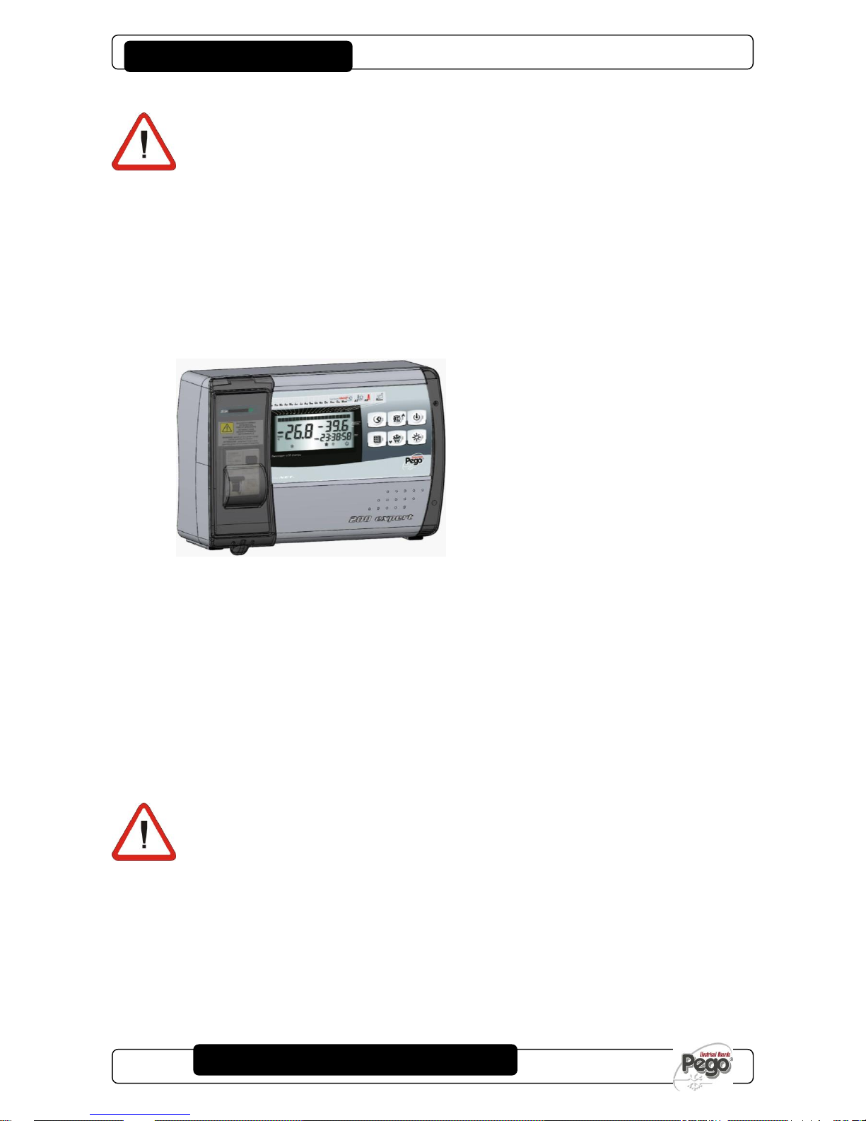
200
200
PLUS200 EXPERT
Gracias por haber elegido un cuadro eléctrico
PEGO.
Este manual suministra información detallada sobre la
instalación, el uso y el mantenimiento de los cuadros
eléctricos de la serie PLUS200 EXPERT y de las versiones
especiales. Nuestros productos están diseñados y
fabricados de acuerdo con las normas de seguridad
vigentes en el campo de uso específico de las
instalaciones de refrigeración y acondicionamiento. El uso
diverso se admite a condición de que se respeten las
condiciones de funcionamiento para las cuales el cuadro
ha sido diseñado y fabricado.
Antes de utilizar el cuadro es oportuno leer integralmente
este manual prestando especial atención a las partes
marcadas con la simbología descrita a continuación:
Thank you for choosing this PEGO electrical panel.
This manual gives detailed information on installation, use
and maintenance of PLUS200 EXPERT electrical
controllers panels and special versions. Our products are
designed and built in compliance with current standards in
the specific fields of refrigeration and conditioning
systems. Different usage is allowed as long as the
working conditions for which the panel has been designed
and built are complied with.
Before using the panel you should read all the contents of
this manual, paying special attention to parts highlighted
parts with the symbols described below:
Con este símbolo se indican notas concernientes las
operaciones de instalación, uso y mantenimiento.
This symbol is used to draw your attention to notes
concerning installation, use and maintenance operations
Este símbolo sirve para destacar notas de particular
importancia.
This symbol is used to highlight important notes
Este símbolo indica la prohibición de realizar la operación
indicada.
This symbol is used to indicate that the described task is
prohibited.
REV. 01/04

PLUS200 EXPERT
Pág. 3
MANUAL DE USO Y MANTENIMIENTO
USE AND MAINTENANCE MANUAL
Rev. 01-16
INTRODUCCIÓN
INTRODUCTION
Pág. 4
1.1
Generalidades
General
Pág. 5
1.2
Códigos de identificación de los productos
Product ID codes
Pág. 5
1.3
Dimensiones totales
Overall dimensions
Pág. 5
1.4
Datos de identificación
Identification data
INSTALACIÓN
INSTALLATION
Pág. 6
2.1
Advertencias generales para el instalador
Important information for the installer
Pág. 6
2.2
Contenido del paquete
Standard assembly kit
Pág. 7
2.3
Instalación del cuadro
Installing the unit
FUNCIONALIDAD
FUNCTIONS
Pág. 11
3.1
Funciones de la tarjeta PLUS200 EXPERT
PLUS200 EXPERT panel functions
CARACTERÍSTICAS TÉCNICAS
TECHNICAL CHARACTERISTICS
Pág. 12
4.1
Características técnicas
Technical characteristics
Pág. 13
4.2
Condiciones de garantía
Warranty
PROGRAMACIÓN DE DATOS
PARAMETER PROGRAMMING
Pág. 14
5.1
Descripción sectores LCD
Description of LCD areas
Pág. 15
5.2
Teclado frontal
Frontal keypad
Pág. 16
5.3
Combinación de teclas
Key combinations
Pág. 16
5.4
Slot secure digital
Secure digital slot
Pág. 17
5.5
Pantalla LED
LED display
Pág. 18
5.6
Generalidades
General features
Pág. 18
5.7
Simbología
Key to symbols
Pág. 18
5.8
Configuración y visualización del setpoint
Setting and displaying set points
Pág. 19
5.9
Programación de primer nivel
Level 1 programming
Pág. 19
5.10
Lista de las variables de primer nivel
List of Level 1 variables
Pág. 21
5.11
Programación de segundo nivel
Level 2 programming
Pág. 21
5.12
Lista de las variables de segundo nivel
List of Level 2 variables
Pág. 25
5.13
Registro de datos
Recording data
Pág. 25
5.14
Visualización de los datos registrados
Displaying recorded data
Pág. 26
5.15
Visualización de las alarmas
Displaying alarms
Pág. 26
5.16
Almacenar los datos en una tarjeta SD
Data backup on SD card
Pág. 28
5.17
Encendido del controlador electrónico
Switching on the electronic controller
Pág. 28
5.18
Condiciones de activación/desactivación del
Compressor activation/deactivation conditions
Pág. 28
5.19
Activación manual de la descongelación
Manual defrosting
Pág. 28
5.20
Descongelación con gas caliente
Hot gas defrosting
Pág. 28
5.21
Modificación de las configuraciones de fecha
Changing the time/date
Pág. 29
5.22
Función pump-down
Pump-down function
Pág. 29
5.23
Protección con contraseña
Password protection
TELENET
TELENET
Pág. 30
6.1
TeleNET
TeleNET
DIAGNÓSTICO
TROUBLESHOOTING
Pág. 31
7.1
Diagnóstico
Troubleshooting
MANTENIMIENTO
MAINTENANCE
Pág. 33
8.1
Normas generales de seguridad
General security rules
Pág. 34
8.2
Control periódico
Periodical check
Pág. 36
8.3
Recambios y accesorios
Spare parts and accessories
Pág. 36
8.4
Limpieza del cuadro
Cleaning the controller
Pág. 36
8.5
Eliminación
Disposal
ANEXOS
APPENDICES
Pág. 37
A.1
Declaración de conformidad CE
EC declaration of conformity
Pág. 38
A.2/A.3/A.4
Esquemas de conexión
Wiring diagrams
Pág. 41
A.5
Despiece
Exploded diagram and parts list
ÍNDICE / CONTENTS
CAP. 7
CAP. 6
CAP. 7
5
6
7
4
3 2 1
CAP. 7
8

PLUS200 EXPERT
Pág. 4
MANUAL DE USO Y MANTENIMIENTO
USE AND MAINTENANCE MANUAL
Rev. 01-16
GENERALIDADES’ – GENERAL
DESCRIPCIÓN:
El PLUS200 EXPERT es un cuadro de control para celdas
frigoríficas con compresor monofásico hasta 2HP que
posee la función Datalogger. El mismo es conforme con el
reglamento (CE) 37/2005 y la relativa norma En 12830,
con las directivas 89/108/CEE, 92/2/CEE y con los
decretos legislativos italianos n. 110 del 27/01/92 y n. 493
del 25/09/95 que obligan a registrar la temperatura de los
congelados y a conservar los relativos datos por al menos
un año.
El PLUS200 EXPERT permite la gestión completa de
todos los componentes presentes en una instalación
frigorífica, visualizar directamente en la pantalla los
registros de temperatura realizados y mediante una
tarjeta Secure Digital transferir los datos memorizados en
el instrumento al programa TeleNET con el cual
organizar, consultar e imprimir gráficos de forma muy
simple.
APLICACIONES:
- Gestión completa de instalaciones frigoríficas
monofásicas de hasta 2HP estáticas o ventiladas,
con descongelación por parada o eléctrica, con
parada del compresor directa o en pump-down
combinada con la función Datalogger.
- Gestión exclusiva de la unidad evaporante
monofásica con habilitación del solenoide freón o
de la unidad motocondensante remota combinada
con la función Datalogger.
CARACTERÍSTICAS PRINCIPALES:
- Gestión directa del compresor, de las resistencias
de descongelación, de los ventiladores del
evaporador, de la luz de la celda con salidas en
tensión conectables directamente a los varios
servicios.
- Función datalogger con registro de la temperatura
ambiente y de las relativas alarmas por 1 año.
Designación del instrumento: EN 12830, S, A, 1,
campo de medida: -45T+45 ºC
- Descarga de datos en la tarjeta de memoria
secure digital
- Circuito autónomo del datalogger como prescrito
por la normativa EN 12830
- Electrónica de control con amplia pantalla LCD
retroiluminada y teclado de uso fácil
- Visualización simultánea de la temperatura
ambiente, la temperatura del evaporador, el
calendario y el estado de la instalación en la
pantalla LCD
- Magnetotérmico diferencial integrado para la
protección y el seccionamiento de la unidad
frigorífica
- Relé auxiliar con activación configurable por
parámetro
- Posibilidad de descongelar en tiempo real
- RS485 para la conexión con la red de supervisión
industrial TeleNET
- Gestión de la temperatura con punto decimal
- Programa TeleNET-SD descargable gratuitamente
del sito internet www.pego.it para el archivo y la
consulta de los datos descargados con la secure
digital de los cuadros PLUS200 Expert.
DESCRIPTION:
The PLUS200 EXPERT is a control unit for refrigeration
rooms with single-phase compressor up to 2 HP. It
features the Datalogger function. It complies with EC
standard 37/2005 and the relative EN 12830 standard, EC
directives 89/108, 92/2 and Italian law decrees n.11 of
27/01/92 and n.493 of 25/09/95, which require that frozen
food temperatures be recorded and that such data be
stored for at least one year.
The PLUS200 EXPERT allows comprehensive
management of all the components on a refrigeration
system and shows temperature recordings directly on the
display; such recording are made by way of a Secure
Digital (SD) card and the data saved on the device can be
transferred on the TeleNET programme to organize,
consult and print graphics easily.
APPLICATIONS:
- Comprehensive management of single-phase
static or ventilated refrigeration systems up to 2
HP, with off-cycle or electrical defrosting and with
direct or pump-down compressor stop linked to
Datalogger function.
- Control of single-phase evaporator unit only with
freon solenoid consensus or remote condensing
unit consensus linked to Datalogger function.
MAIN CHARACTERISTICS:
- Direct control of compressor, defrosting
elements, evaporator fans, room light with
outputs directly connectable to the various units.
- Datalogger function with up to 1 year of cold
room temperature and relevant alarm recordings.
Instrument designation: EN 12830, S, A, 1,
measuring range: -45T +45 C°
- Data download into secure digital memory card
- Independent datalogger circuit as per EN 12830
- Control electronics with large backlit LCD display
and user-friendly keypad.
- Simultaneous display on the LCD of cold room
temperature, evaporator temperature, calendar
and system status.
- Magneto-thermal cut-out switch for isolation and
protection of refrigeration unit.
- Auxiliary relay with parameter-configured
activation.
- Defrosting can be carried out in real time clock
mode.
- RS485 for connection to the TeleNET industrial
supervision network
- Temperature control to 0.1 °C.
- The TeleNET-SD programme can be
downloaded free of charge from www.pego.it to
allow storage and consultation of data
downloaded with the secure digital card from
PLUS200 Expert panels.
INTRODUCCIÓN / INTRODUCTION
1 Introducción - Introduction
PLUS200 EXPERT
Pág. 5
MANUAL DE USO Y MANTENIMIENTO
USE AND MAINTENANCE MANUAL
Rev. 01-16
CÓDIGOS DE IDENTIFICACIÓN DE LOS PRODUCTOS - PRODUCT ID CODES
200P200EDL
PLUS200 EXPERT
Control y gestión de la celda con compresor
monofásico hasta 2HP estática o ventilada y
función Datalogger. (hasta 1 año de registro). Slot
Secure Digital de descarga de datos. Interruptor
magnetotérmico diferencial de protección general
16 A curva C Id=300 mA.
Salidas en tensión (230 V) excepto el contacto
Aux/All.
PLUS200 EXPERT
Control and management of cold rooms with singlephase compressor up to 2 HP, static or ventilated, and
Datalogger function (up to 1 year of recordings.
Secure Digital data download slot. General protection
magneto-thermal cut-out switch 16A, C curve,
Id=300mA.
Live outputs (230 V) excluding Aux/All contact.
200P200EDLCR
PLUS200 EXPERT CR
Control remoto para la habilitación del compresor, de
la descongelación, de los ventiladores a combinar con
el cuadro de potencia versión CR.
Control y gestión de la celda con compresor
monofásico hasta 2HP estática o ventilada y función
Datalogger. (hasta 1 año de registro). Slot Secure
Digital de descarga de datos.
Salidas con contactos libres.
PLUS200 EXPERT CR
Remote control for compressor, defrosting, fans
consensus to be connected to CR version power
board.
Cold room control and management with single-phase
compressor up to 2HP, static or ventilated, and
Datalogger function (up to 1 year of recordings.
Secure Digital data download slot.
Clean-contact outputs.
200P200EDLCR2
PLUS200 EXPERT CR + MAGN.
Control remoto para la habilitación del compresor, de
la descongelación, de los ventiladores a combinar con
el cuadro de potencia versión CR.
Control y gestión de la celda con compresor
monofásico hasta 2HP estática o ventilada y función
Datalogger. (hasta 1 año de registro). Slot Secure
Digital de descarga de datos. Interruptor
magnetotérmico diferencial de protección general
16 A curva C Id=300 mA.
Salidas con contactos libres.
PLUS200 EXPERT CR + MAGN.
Remote control for compressor, defrosting, fans
consensus to be connected to CR version power
board.
Cold room control and management with single-phase
compressor up to 2HP, static or ventilated, and
Datalogger function (up to 1 year of recordings.
Secure Digital data download slot. General protection
magneto-thermal cut-out switch 16A, C curve,
Id=300mA.
Clean-contact outputs.
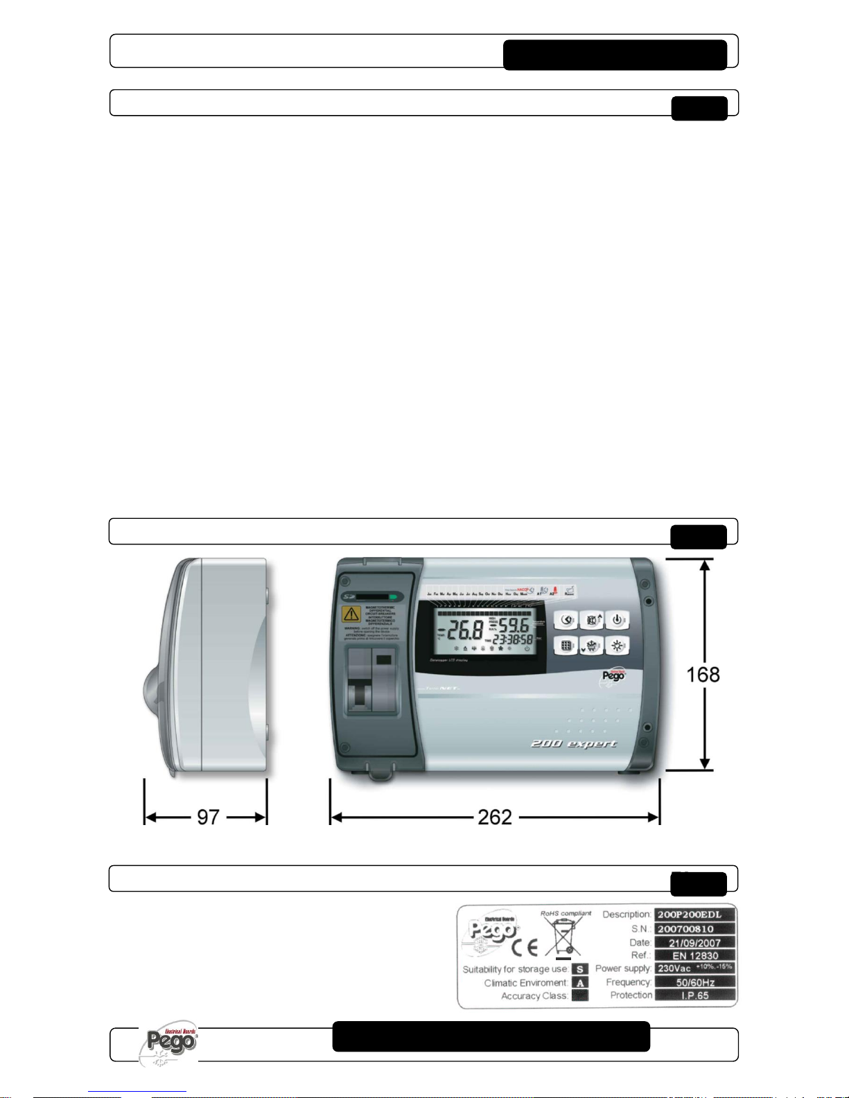
DIMENSIONES TOTALES - OVERALL DIMENSIONS
CÓDIGO DE IDENTIFICACIÓN DEL PRODUCTO - IDENTIFICATION DATA
El equipo descrito en el
presente manual tiene una placa
en el lado, con los datos de
identificación del mismo:
The device described in this
manual comes with a nameplate
attached to its side showing the
identification data of the device:
Dimensiones en
Dimensions (mm.)
1 Introducción - Introduction
1

PLUS200 EXPERT
Pág. 6
MANUAL DE USO Y MANTENIMIENTO
USE AND MAINTENANCE MANUAL
Rev. 01-16
ADVERTENCIAS PARA EL INSTALADOR - IMPORTANT INFORMATION FOR THE INSTALLER
- Instale el equipo en lugares que respeten el grado de
protección y trate de mantener la caja lo más íntegra
posible en el momento en que se realizan las
perforaciones para el alojamiento de los prensacables
y/o de los sujeta tubos.
- Evite usar cables multipolares en los que haya
conductores conectados a cargas inductivas y de
potencia y conductores de señal como sondas y
entradas digitales.
- Evite alojar cables de alimentación y cables de señal
(sondas y entradas digitales) en el mismo conducto.
- Reduzca lo más posible el largo de los cables de
conexión evitando que el cableado tome la forma
espiralada dañosa por posibles efectos inductivos
sobre la electrónica.
- Todos los conductores empleados en el cableado
deben ser oportunamente proporcionados para
soportar la carga que deben alimentar.
- Si es necesario prolongar las sondas es obligatorio
usar conductores con una sección adecuada y de
todas formas superior a 1 mm .
La prolongación o reducción de las sondas puede
alterar la calibración de fábrica; por lo tanto realice el
control y la calibración mediante un termómetro
probado y certificado ACCREDIA.
- Install the device in places where the protection rating
is observed and try not to damage the box when
drilling holes for wire/pipe seats.
- Do not use multi-polar cables in which there are wires
connected to inductive/power loads or signalling wires
(e.g. probes/sensors and digital inputs).
- Do not fit power supply wiring and signal wiring
(probes/sensors and digital inputs) in the same
raceways or ducts.
- Minimise the length of connector wires so that wiring
does not twist into a spiral shape as this could have
negative effects on the electronics.
- All wiring must be of a cross-section suitable for
relevant power levels.
- When it is necessary to make a probe/sensor
extension, the wires must have a cross-section of at
least 1 mm2. Extending or shortening the probes could
alter factory calibration; proceed with testing and
calibration by means of a ACCREDIA-tested and
certified thermometer.
CONTENIDO DEL PAQUETE - STANDARD ASSEMBLY KIT
El controlador electrónico PLUS200 EXPERT, para el
montaje y el uso cuenta con:
n.° 3 juntas de estanqueidad para colocar entre el
tornillo de fijación y el fondo de la caja;
n.° 1 Manual de uso;
n.° 1 sonda NTC 10K 1% negra, longitud =1,5 m;
n.° 1 sonda NTC 10K 1% gris, longitud =3 m;
n.° 1 sonda NTC 10K 1% amarilla, longitud =3 m;
n.° 1 CD-ROM programa TeleNET-SD;
n.° 1 guía sintética importación SD;
n.° 1 reporte de calibración.
PLUS200 EXPERT electronic controller for installing and
using, is equipped with:
N° 3 Seals, to be fitted between the fixing screws and
the box back panel.
N° 1 User’s manual.
N° 1 NTC 10K 1% probe black length 1.5 m
N° 1 NTC 10K 1% probe grey length 3 m
N° 1 NTC 10K 1% probe yellow length 3 m
N° 1 TeleNET-SD CD-ROM
N° 1 Syntethic guide for SD import
N° 1 Calibration report
INSTALACIÓN / INSTALLATION
2 - Instalación- Installation
PLUS200 EXPERT
Pág. 7
MANUAL DE USO Y MANTENIMIENTO
USE AND MAINTENANCE MANUAL
Rev. 01-16
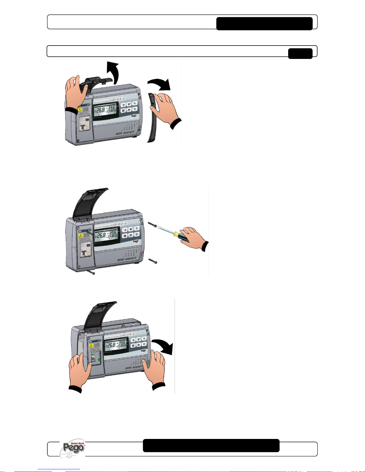
INSTALACIÓN DEL CUADRO - INSTALLING THE UNIT
Fig. 1:
Levante la puerta transparente de protección del
magnetotérmico diferencial y quite la cobertura
de los tornillos en el lado derecho.
Raise the transparent cover that shields the
magneto-thermal cut-out switch and remove the
screw cover on the right-hand side.
Fig. 2:
Desenrosque los 4 tornillos del frontal de la caja.
Undo the 4 fixing screws at the front of the box.
Fig. 3:
Abra el frontal de la caja levantándolo y haciendo
desplazar las dos bisagras hasta el final de
carrera.
Fleccione las bisagras y gire el frontal de 180 º
hacia abajo para acceder al interior del cuadro.
Open the front of the box, lift it and slide the two
hinges out as far as they will go. Bend the hinges
and rotate the front panel by 180° downward to
get access inside the panel
2 - Instalación- Installation
PLUS200 EXPERT
Pág. 8
MANUAL DE USO Y MANTENIMIENTO
USE AND MAINTENANCE MANUAL
Rev. 01-16
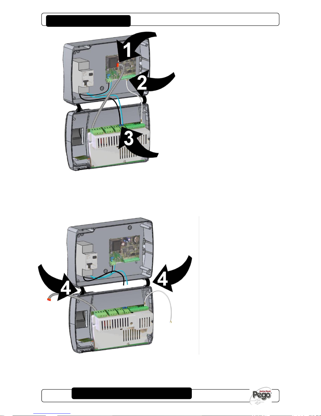
Fig. 4:
Desconecte el conector FLAT (1), el cable de
comunicación entre Recorder y Tarjeta (2) y los
cables de alimentación de la tarjeta (3).
Disconnect FLAT plug (1), communication cable
between Recorder and Card (2) and card power
supply wiring (3).
Fig. 5:
Ejerza una presión en los lados de cada bisagra
para extraerla de su alojamiento y quite
completamente el frontal.
Press on the sides of the hinges to remove them
from their seats and so remove the front panel
completely.
2 - Instalación- Installation

PLUS200 EXPERT
Pág. 9
MANUAL DE USO Y MANTENIMIENTO
USE AND MAINTENANCE MANUAL
Rev. 01-16
Fig. 6:
Utilizando los tres agujeros presentes, fije el
fondo de la caja con tres tornillos de longitud
adecuada en relación con el espesor de la pared
en la que se va a fijar el cuadro. Interponga una
arandela de goma (suministrada) entre cada
tornillo y el fondo de la caja.
Use the three existing holes to fix the box back
panel to the wall: use three screws of a length
suitable for the thickness of the wall to which the
panel will be attached. Fit a rubber washer
(supplied) between each screw and the box
backing.
Fig. 7:
Vuelva a enganchar el frontal al fondo de la caja
volviendo a introducir las bisagras en los
correspondientes alojamientos y fleccionándolas
gírelo todo de 180º hacia abajo para acceder a la
tarjeta electrónica.
Hook the frontal panel back up to the lower part
of the box by inserting the two hinges in their
seats and, bending them, rotate downwards 180°
to gain access to the electronic board.
2 - Instalación- Installation
PLUS200 EXPERT
Pág. 10
MANUAL DE USO Y MANTENIMIENTO
USE AND MAINTENANCE MANUAL
Rev. 01-16
Realice todas las conexiones eléctricas según los
esquemas adjuntos para el modelo
correspondiente (vea las relativas tablas en
ANEXOS). Para realizar correctamente las
conexiones eléctricas y mantener el grado de
protección de la caja se aconseja utilizar
prensacables y/o sujeta tubos apropiados para
apretar todos los cableados de forma estanca. Se
aconseja distribuir el paso de los conductores
dentro del cuadro lo más ordenadamente posible,
y sobre todo, alejar los conductores de potencia
de los de señal. Use eventuales abrazaderas de
sujeción.
Make all the electrical connections as illustrated
in the diagram for the corresponding model (see
relative table in APPENDICES).
To effect correct electrical connection and
maintain the protection rating, use appropriate
wire/raceway grips to ensure a good seal.
Route the wiring inside the unit in as tidy a
fashion as possible: be especially careful to keep
power wires away from signal wires. Use clips to
hold wires in place.
Fig. 8:
Vuelva a cerrar la tapa frontal, prestando
atención a que todos los cables estén dentro de
la caja y a que la junta de la caja esté colocada
correctamente en su alojamiento. Apriete la tapa
frontal con los 4 tornillos reutilizando las juntas
tóricas presentes en la ranura de cada tornillo.
Suminístrele corriente al cuadro y realice una
escrupulosa lectura/programación de todos los
parámetros configurados.
Close the front panel, making sure that all the
wires are inside the box and that the box seal sits
in its seat properly.
Tighten the front panel using the 4 screws,
making sure the O-rings on the head of each
screw are used.
Power up the panel and carry out thorough
reading/programming of all parameters.
Preste atención a no apretar excesivamente los
tornillos de cierre porque podrían deformar la caja
y alterar el funcionamiento correcto y el efecto
táctil del teclado del cuadro. Instale dispositivos
de protección de sobrecorrientes para
cortocircuitos en todas las cargas conectadas al
controlador electrónico ECP200, para evitar que
el dispositivo se dañe. Las operaciones de
intervención y/o mantenimiento se deben realizar
desconectando el cuadro de la alimentación
eléctrica y de todas las posibles cargas inductivas
y de potencia a las que resulta estar conectado.
De esta forma se garantiza la condición de
máxima seguridad para el operador.
Be careful not to over-tighten the closure screws
as this could warp the box and compromise
proper operation of the membrane-type keypad.
Install short-circuit overload safety devices on all
the power cables connected to the ECP200
EXPERT so as to prevent damage to the device.
Work and/or maintenance must ONLY be carried
out on the unit after disconnecting the panel from
the power supply and from any inductive/power
loads: doing so allows the worker to do his job in
complete safety.
2 - Instalación- Installation

PLUS200 EXPERT
Pág. 11
MANUAL DE USO Y MANTENIMIENTO
USE AND MAINTENANCE MANUAL
Rev. 01-16
FUNCIONES GESTIONADAS POR EL C.E. PLUS200 EXPERT – PLUS200 ESPERT PANEL FUNCTIONS
Visualización y regulación de la temperatura de la celda
con punto decimal
Display and adjustment of cold room temperature
accurate to 0.1 °C.
Visualización de la temperatura del evaporador
Display of evaporator temperature
Visualización de la temperatura recorder plus de
parámetro
(sonda di registro)
Display of recorder temperature from parameter
(datalogger probe)
Activación/desactivación del control instalación
System control activation/deactivation
Señalización de las alarmas de la instalación (error de
sonda, alarma de mínima y máxima temperatura,
protección del compresor, alarma operador en celda)
System warnings (probe/sensor errors, minimum and
maximum temperature warnings, compressor shutdown,
man in cold room alarm)
Gestión de los ventiladores del evaporador
Evaporator fans control
Gestión de la descongelación automática y manual
(estática, de resistencias, de inversión de ciclo)
Automatic and manual defrost (static, heating element,
cycle inversion)
Gestión y control directo de la unidad motocompresor
hasta 2HP con salidas en tensión conectables
directamente a los diferentes servicios (modelo PLUS200
EXPERT) o con contactos libres (modelo PLUS200
EXPERT CR)
Direct control of compressor unit up to 2 HP with live
outputs connectable directly to the various units (model
PLUS200 EXPERT) or with clean contacts (model
PLUS200 EXPERT CR)
Activación de la luz de la celda con una tecla en el cuadro
o mediante micro puerta
Room light, via panel key or door switch
Función Contraseña para la gestión de 4 niveles de
acceso a los parámetros del instrumento
Password function for management of 4 levels of access
to instrument parameters
Reloj para descongelar en tiempo real
Real time defrost clock
Relé alarma / auxiliar con activación configurable por
parámetro
Alarms / Auxiliary relay with activation configurable by
parameter
Registro de las temperaturas y alarmas de temperatura
con disponibilidad de los datos hasta un año (instrumento
conforme con la norma EN 12830)
Recording of temperatures and temperature alarms for up
to 1 year (instrument is EN 12830 compliant)
RS485 para la conexión con la red de monitorización /
supervisión TeleNET
RS485 for connection to TeleNET industrial supervision
network
Slot Secure Digital para descarga
Secure Digital data download slot
Interruptor magnetotérmico diferencial de protección
general 16 A curva C Id=300 mA (modelo PLUS200
EXPERT)
General protection magneto-thermal cut-out switch 16A, C
curve, Id=300mA. (PLUS200 EXPERT model)
FUNCIONALIDAD / FUNCTIONS
CAP. 3 - Funcionalidad / Functions
PLUS200 EXPERT
Pág. 12
MANUAL DE USO Y MANTENIMIENTO
USE AND MAINTENANCE MANUAL
Rev. 01-16
-
CARACTERÍSTICAS TÉCNICAS - TECHNICAL CHARACTERISTICS
(*)
200P200EDL: Salidas en tensión (230 V)
200P200EDLCR: Salidas con contactos
libres
200P200EDL: Live outputs (230V)
200P200EDLCR: Clean-contact outputs
(**)
solo en la versión 200P200EDL
only on the 200P200EDL version
Alimentación
Power supply
Tensión
Voltage
230 V~ (+ 10% -15%)
Frecuencia
Frequency
50 Hz / 60 Hz
Potencia máx. absorbida (solo controles
electrónicos)
Max power (only electronic controls)
~ 7 VA
Condiciones climáticas
Cold room conditions
Temperatura de trabajo
Working temperature
0T50 °C
Temperatura de almacenamiento
Storage temperature
-20T60 °C
Humedad relativa ambiente (no
Relative humidity (non condensing)
Inferior al 90% HR
Características generales
General characteristics
Tipo de sondas conectables
Type of sensors that can be connected
NTC 10K 1%
Resolución
Resolution
0,1 °C
Campo de medida
Read range
-45T45 °C
Clase de precisión
Accuracy class
1
Características función registro
Data recording characteristics
Número máximo de registros en la memoria
interna sin sobreescrituras
Maximum number of recordings on internal
memory without overwrite
75776
Protección eléctrica general
General electrical protection
Interruptor magnetotérmico
diferencial bipolar 16 A, curva C
Id=300 mA (**)
Bipolar magneto-thermal cut-out
switch 16A, C curve, Id=300mA
(**)
Entradas
Input
Entradas analógicas para sondas NTC
Analogue inputs for NTC probes
3
Entradas digitales configurables
Configurable digital inputs
3
Salidas
Output
Compresor
Compressor
1500 W (AC3) (*)
Resistencias
Elements
3000 W (AC1) (*)
Ventiladores
Fans
500 W (AC3) (*)
Luz de la celda
Room light
800 W (AC1) (*)
Alarma / Aux (contacto libre de tensión)
Alarm contact (non-powered contact)
100 W
Características dimensionales
Dimensional characteristics
Dimensiones
Dimensions
16.8x9.7x26.2 cm (HxPxL)
Características de aislamiento y mecánicas
Insulation / mechanical characteristics
Grado de protección de la caja
Box protection rating
IP65
Material de la caja
Box material
ABS autoextinguible
Tipo de aislamiento
Type of insulation
Clase II
Designación
Designation
referencia normativa
reference standards
EN 12830
adecuación
appropriateness
S (conservación / upkeep)
tipo de ambiente climático
type of ambient climate
A
Clase de precisión
accuracy class
1
Campo de medida
measurement range
°C
4 - Características técnicas-Technical characteristics
CARACTERÍSTICAS TÉCNICAS / TECHNICAL CHARACTERISTICS
PLUS200 EXPERT
Pág. 13
MANUAL DE USO Y MANTENIMIENTO
USE AND MAINTENANCE MANUAL
Rev. 01-16
Los controles electrónicos serie PLUS200 EXPERT
están cubiertos por garantía contra todos los
defectos de fabricación por 24 meses a partir de la
fecha indicada en el código de identificación del
producto.
PLUS 200 EXPERT control units are covered by a
24-month warranty against all manufacturing
defects as from the date indicated on the product
ID code.
En caso de defecto, el equipo se debe enviar con
un embalaje adecuado a nuestro Establecimiento o
Centro de asistencia autorizado.
In the event of a defect the product must be
appropriately packaged and sent to our factory or
any authorized Service Center.
El cliente tiene el derecho a la reparación del
equipo defectuoso que incluye la mano de obra y
las piezas de repuesto. Los gastos y los riesgos de
transporte son completamente a cargo del Cliente.
Customers are entitled to have defective products
repaired, spare parts and labour included.
Transport expenses and risk shall be met entirely
by the customer.
Las intervenciones realizadas bajo garantía no
extienden ni renuevan el vencimiento de esta.
Repairs carried out under warranty do not prolong
or renew the warranty expiration date.
La garantía se pierde por:
o daño o alteración debidos a incuria o
negligencia del usuario;
o comportamiento no conforme con las
prescripciones e instrucciones del fabricante;
o intervenciones de reparación realizadas por
personal no autorizado.
En estos casos todos los costes de reparación son
a cargo del cliente.
The Warranty does not cover:
o Damages resulting from tampering, impact or
improper installation.
o Behaviour inconsistent with Manufacturer’s
prescriptions and instructions.
o Damages caused by repairs made by
unauthorized persons.
In all such cases repair cost shall be charged to
the Customer in full.
El servicio de intervención en garantía se puede
rechazar cuando el equipo resulta modificado o
transformado.
Warranty cover may be refused if the device is
modified or changed.
El fabricante declina toda responsabilidad por
eventuales daños directos o indirectos a personas,
animales o cosas debidos al incumplimiento de
todas las disposiciones del manual de uso y, sobre
todo, de las advertencias sobre la instalación, el
uso y el mantenimiento del equipo.
The Manufacturer cannot be held liable for any
direct or indirect damages to animals, people or
things as a result of failure to observe all the
instructions/information in the user manual,
especially instructions regarding installation, use
and maintenance of the device.
En relación con lo que no se indica expresamente,
se aplican a la garantía las normas de ley en vigor y
en particular el art. 1512 C.C.
For all matters not expressly indicated, the
warranty is subject to the regulations contained in
the Italian Civil Code art. 1512.
En caso de controversia, se entiende como elegida
y reconocida por las partes, la competencia del
Tribunal de Rovigo.
The competent court for any controversies is
acknowledged to be the “Foro di Rovigo”.
PEGO S.r.l. declina toda responsabilidad por las
posibles imprecisiones contenidas en el presente
manual, si se deben a errores de impresión o
transcripción.
PEGO S.r.l. cannot be held liable for possible
errors or inaccuracies written in this manual as a
result of printing or transcription errors.
PEGO S.r.l. se reserva el derecho de aportar a sus
productos las modificaciones que retiene
necesarias o útiles sin perjudicar sus características
esenciales, y sin previo aviso.
PEGO S.r.l. reserves the right to modify its
products without prior notice as it deems
necessary without altering their main
characteristics.
Cada nueva versión de los manuales de los
productos PEGO sustituye todas las anteriores.
Each new release of a PEGO user manual
replaces previous ones.
4 - Características técnicas - Technical characteristics
CONDICIONES DE GARANTÍA - WARRANTY

PLUS200 EXPERT
Pág. 14
MANUAL DE USO Y MANTENIMIENTO
USE AND MAINTENANCE MANUAL
Rev. 01-16
DESCRIPCIÓN SECTORES LCD - DESCRIPTION OF LCD AREAS
ICONOS FECHADOR
Visualización del mes corriente (se quedan
encendidos también los meses anteriores) En modo
de visualización de las temperaturas registradas, se
queda encendido solo el mes de referencia (con UP
y DOWN se pueden recorrer los diferentes meses).
DATE ICONS
Display of current month (previous months also
remain on). In recorded temperature display mode,
only the reference month stays on (use UP and
DOWN to scroll the months).
ICONOS FASES DE BÚSQUEDA
Visualización de la fase de búsqueda, evidencia si
se está seleccionando el mes, el día o la hora
(encendido intermitente solo el de referencia)
SEARCH STAGE ICONS
Search phase display: highlights whether the month,
day or hour is being selected (relevant indicator
flashes).
ICONO HISTÓRICO DE LAS TEMPERATURAS Y
ALARMAS
Búsqueda de las temperaturas registradas con las
relativas alarmas
TEMPERATURE AND ALARM HISTORY ICON
Recorded temperatures search.
ICONO HISTÓRICO DE LAS ALARMAS
Búsqueda de las alarmas visualizadas
ALARM HISTORY ICON
Displayed alarms search.
ICONO ALARMA TEMPERATURA
Señalización de que la temperatura visualizada ha
dado una señal de alarma
TEMPERATURE ALARM ICON
Warning showing that displayed temperature has
generated an alarm.
ICONO RECORD
Visualización del registro en curso (int0).
Encendido está en fase de registro.
RECORD ICON
Data being recorded (int0). Comes on when data is
saved.
PROGRAMACIÓN DE DATOS / PARAMETER PROGRAMMING
5 - Programación de datos - Parameter programming
PLUS200 EXPERT
Pág. 15
MANUAL DE USO Y MANTENIMIENTO
USE AND MAINTENANCE MANUAL
Rev. 01-16
TECLADO FRONTAL - FRONTAL KEYPAD
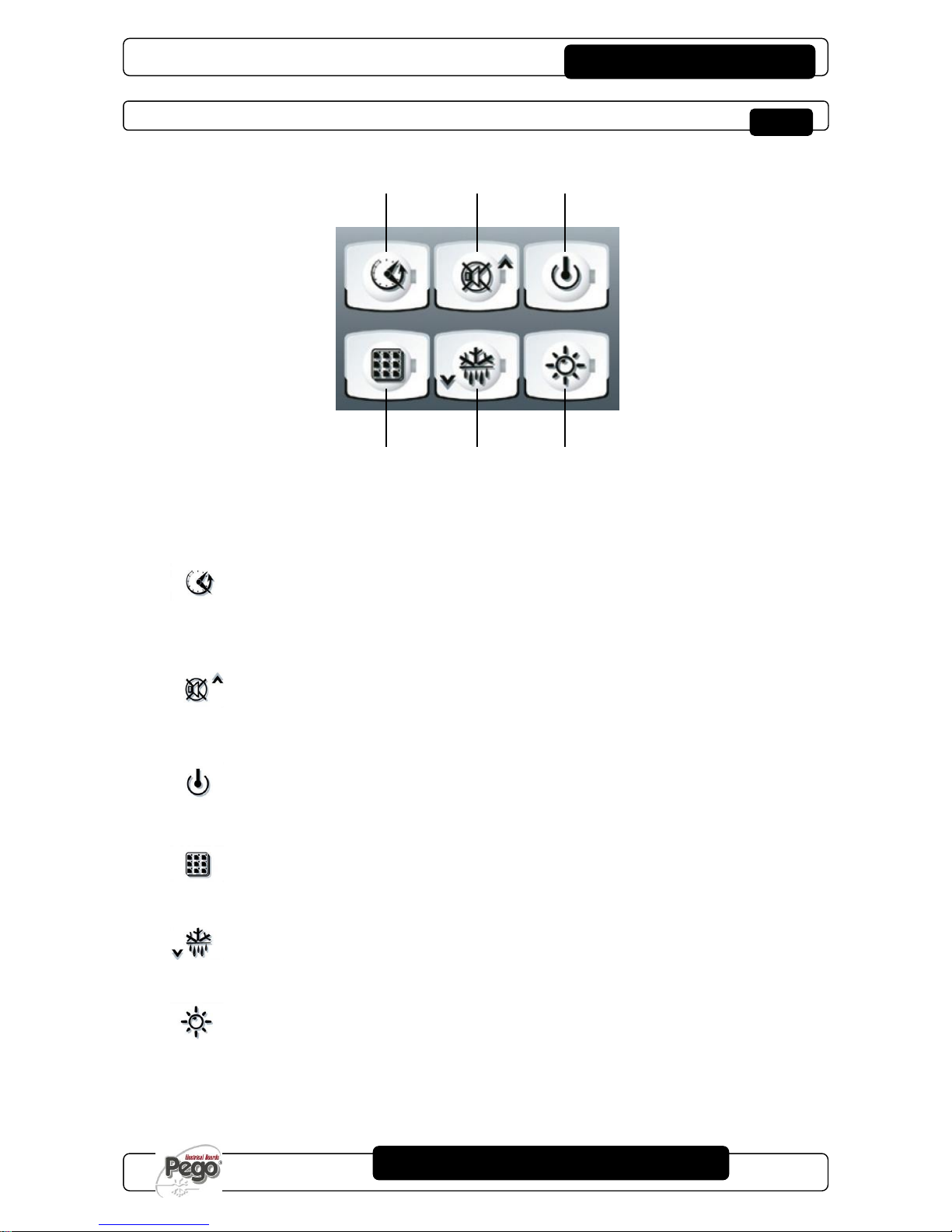
TECLA VISUALIZACIÓN DE DATOS
Si se pulsa instantáneamente muestra el n.º serial.
Si se pulsa durante 5 s entra en visualización
de datos registrados.
Si se pulsa durante 5 s junto con la tecla 4,
entra en almacenamiento de datos en la tarjeta
Secure Digital.
DATA DISPLAY KEY
If pressed momentarily it immediately shows the
serial number.
If pressed for 5 seconds saved data is displayed.
If pressed for 5 seconds, together with key 4, it
goes to data saving on Secure Digital card.
TECLA UP / DESACTIVACIÓN DEL
ZUMBADOR ALARMA
Si se pulsa durante 5 s junto con la tecla 1,
entra en visualización de alarmas registradas.
Si se pulsa durante una alarma silencia el
zumbador.
UP / ALARM BUZZER MUTE KEY
If pressed for 5 seconds, together with key 1,
displays recorded alarms.
If pressed during an alarm the buzzer is muted.
TECLA STAND BY
Si se pulsa, la instalación se detiene y la
temperatura ambiente parpadea (salidas
compresor, descongelación, ventiladores
desactivadas).
STAND BY KEY
If pressed the system stops and cold room
temperature flashes (compressor outputs,
defrosting, fans deactivated)
TECLA SET
Si se pulsa, visualiza el set de temperatura
ambiente y en combinación con las teclas 2 y 5,
lo configura.
SET KEY
If pressed the cold room temperature setting is
displayed; the setting is made in combination
with keys 2 and 5.
TECLA DOWN / DEFROST MANUAL
Si se pulsa durante 5 s y subsisten las
condiciones activa la descongelación.
DOWN / MANUAL DEFROST KEY
If pressed for 5 seconds and conditions are met
defrosting is activated.
TECLA LUZ DE LA CELDA
Activa y desactiva la luz de la celda.
ROOM LIGHT KEY
Switches room light on/off.
5 - Programación de datos - Parameter programming

PLUS200 EXPERT
Pág. 16
MANUAL DE USO Y MANTENIMIENTO
USE AND MAINTENANCE MANUAL
Rev. 01-16
COMBINACIÓN DE TECLAS – KEYS COMBO
+
HISTÓRICO DE LAS ALARMAS
REGISTRADAS
Si se pulsan durante 5 s se entra en
visualización de las alarmas registradas.
RECORDED ALARM HISTORY
If pressed for 5 seconds recorded alarms
are displayed.
+
ALMACENAMIENTO DE DATOS EN LA
TARJETA
Si se pulsa durante 5 se habilita el
almacenamiento de datos de la memoria interna
en la tarjeta . Cuando aparece la pregunta
SAvE no/YES seleccione YES con las teclas
() y () y confirme con la tecla 4 SET.
SAVING DATA ON CARD
If pressed for 5 seconds saving of data on
the internal memory of the card is
enabled When you see the question SAvE
no/YES select YES with keys 2 and 5 and
confirm saving with key 4.
+
PROGRAMACIÓN DE 1° NIVEL
Si se pulsan durante algunos segundos
permite acceder al menú programación de
primer nivel.
Si se pulsan durante algunos segundos
dentro de un menú, al salir del menú se
guardan las configuraciones realizadas.
LEVEL 1 PROGRAMMING
If pressed for a few seconds access to the
Level 1 programming menu is granted.
If pressed for a few seconds inside a
menu the effected settings are saved and
the user exits from the menu.
+
+
PROGRAMACIÓN DE 2° NIVEL
Si se pulsan durante algunos segundos
permiten acceder al menú programación
de segundo nivel.
LEVEL 2 PROGRAMMING
If pressed for a few seconds access to the
Level 2 programming menu is granted.
SLOT SECURE DIGITAL - SECURE DIGITAL SLOT
SLOT SECURE DIGITAL
Introduzca la flash card con el lado redondeado
por el lado derecho.
SECURE DIGITAL SLOT
Insert the flash card with the chamfered side on
the right.
INDICADOR DE ESTADO SECURE DIGITAL
Encendido fijo: Indica que la secure digital está
introducida.
Intermitente: Indica el almacenamiento de datos en
SECURE DIGITAL STATUS LIGHT
On continuously: indicates that secure digital card is
inserted.
Flashing: indicates saving is in progress.
FLASH CARD
Use modelos de con capacidad inferior a 2 GB
y con velocidad de 80x (Ultra-Speed) o 150x
(Extreme-Speed).
FLASH CARD
Use models of capacities no greater than 2 GB
and with speeds of 80x (Ultra-Speed) or 150x
(Extreme-Speed).
5 - Programación de datos - Parameter programming

PLUS200 EXPERT
Pág. 17
MANUAL DE USO Y MANTENIMIENTO
USE AND MAINTENANCE MANUAL
Rev. 01-16
PANTALLA LCD - LCD DISPLAY
PANTALLA PRINCIPAL
Valor de temperatura ambiente / Parámetros
MAIN DISPLAY
Cold room temperature / Parameters.
PANTALLA SECUNDARIA
Valor de temperatura del evaporador / Día del mes
corriente (vea la configuración del parámetro tEu del
1º nivel de programación) / Parámetros (en fase de
programación)
SECONDARY DISPLAY
Evaporator temperature value / Day of current month
(see tEu parameter setting of 1st programming level)
/ Parameters (in programming mode).
PANTALLA HORARIO
Horario / Fecha / Valores de los parámetros tiempo
TIME DISPLAY
Time / Date information.
ICONO PROGRAMACIÓN
Encendido fijo: Programación en curso.
PROGRAMMING ICON
On continuously: Programming in progress.
ICONO FRÍO
Encendido fijo: Llamada compresor
COLD ICON
On continuously: Compressor call
ICONO DESCONGELACIÓN
Encendido fijo: Descongelación en curso
Intermitente: Goteo en curso
DEFROSTING ICON
On continuously: Defrosting in progress.
Flashing: Drip in progress.
ICONO VENTILADORES
Encendido fijo: Ventiladores del evaporador en
funcionamiento
FANS ICON
On continuously: Evaporator fans working.
ICONO LUZ
Encendido fijo: luz de la celda activada
Intermitente: luz de la celda activada por la micro
puerta.
LIGHT ICON
On continuously: room light on.
Flashing: room light activated by door switch.
ICONO ALARMA
Intermitente: Alarma activa
ALARM ICON
Flashing: Alarm active.
ICONO STAND-BY
Intermitente: Instalación en stand-by (salidas para
el compresor, los ventiladores, la descongelación
desactivadas)
STAND-BY ICON
Flashing: Plant on stand-by (compressor, fan,
defrost outputs deactivated).
5 - Programación de datos - Parameter programming
PLUS200 EXPERT
Pág. 18
MANUAL DE USO Y MANTENIMIENTO
USE AND MAINTENANCE MANUAL
Rev. 01-16
GENERALIDADES - GENERAL FEATURES
Por razones de seguridad y de mayor practicidad para el
operador el sistema PLUS200 EXPERT prevé dos niveles
de programación; el primero, solo para la configuración de
los parámetros de SETPOINT modificables
frecuentemente y el segundo, para la programación y la
configuración de los parámetros generales relativos a los
varios modos de funcionamiento de la tarjeta.
Si se encuentra en programación en el primer nivel no se
puede acceder directamente al segundo nivel sino que es
necesario salir primero de la programación.
To enhance safety and simplify the operator’s work, the
PLUS200 EXPERT system has two programming levels;
the first level (Level 1) is used to configure the frequentlymodified SETPOINT parameters. The second
programming level (Level 2) is for general parameter
programming of the various controller work modes.
It is not possible to access Level 2 programming directly
from Level 1: you must exit the programming mode first.
SIMBOLOGÍA - KEY TO SYMBOLS
Por comodidad indicaremos con los símbolos:
• () la tecla UP que realiza las funciones
de aumento del valor y desactivación de la
alarma;
• () la tecla DOWN que realiza las funciones
de disminución del valor y forzamiento
de la descongelación
For purposes of practicality the following symbols are
used:
• () the UP key is used to increase
values and mute the alarm.
• () the DOWN key is used to decrease
values and force defrosting.
CONFIGURACIÓN Y VISUALIZACIÓN DEL SETPOINT - SETTING AND DISPLAYING THE SET
POINTS
1. Pulse la tecla SET para visualizar el valor de
SETPOINT corriente (temperatura).
2. Si mantiene pulsada la tecla SET y pulsa una de las
teclas () o () se modifica el valor de SETPOINT.
3. Suelte la tecla SET para regresar a la visualización
de la temperatura de la celda, las modificaciones
aportadas se memorizan automáticamente.
1. Press the SET key to display the current SETPOINT
(temperature)
2. Hold down the SET key and press the () or ()
keys to modify the SETPOINT.
3. Release the SET key to return to cold room
temperature display: the new setting will be saved
automatically.
5.8
5 - Programación de datos - Parameter programming
PLUS200 EXPERT
Pág. 19
MANUAL DE USO Y MANTENIMIENTO
USE AND MAINTENANCE MANUAL
Rev. 01-16
PROGRAMACIÓN DE 1° NIVEL (Nivel usuario) - LEVEL 1 PROGRAMMING (User level)
Para acceder al menú de configuración de primer nivel es
necesario:
1. Pulsar simultáneamente y mantener pulsados por
algunos segundos las teclas () y () hasta que
en la pantalla aparezca la primera variable de
programación;
2. Soltar las teclas () y ();
3. Con las teclas () o () seleccionar la variable que
hay que modificar;
4. Después de haber seleccionado la variable deseada
es posible:
Visualizar su configuración pulsando la tecla
SET;
Modificar su configuración manteniendo
pulsada la tecla SET y pulsando una de las
teclas () o ().
5. Al finalizar la programación de los valores de
configuración, para salir del menú pulse
simultáneamente y mantenga pulsadas durante
algunos segundos las teclas () y () hasta que
aparezca el valor de la temperatura de la celda.
6. Las modificaciones aportadas a las variables se
memorizan de manera automática cuando se sale del
menú de configuración.
To gain access to the Level 1 configuration menu proceed
as follows:
1. Press the () and () keys simultaneously and
keep them pressed for a few seconds until the first
programming variable appears on the display.
2. Release the () and () keys.
3. Select the variable to be modified using the () or
() key.
4. When the variable has been selected it is possible:
to display the setting by pressing SET.
to modify the setting by pressing the SET key
and the() or () keys.
5. When configuration values have been set you can
exit the menu by pressing the () and () keys
simultaneously for a few seconds until the cold room
temperature reappears.
6. The new settings are saved automatically when you
exit the configuration menu.
LISTA DE LAS VARIABLES DE 1° NIVEL (Nivel usuario) - LEVEL 1 PROGRAMMING (User level)
VARIABLES VARIABLES
SIGNIFICADO
VALORES MEANING
VALUE
DEFAULT
r0
Diferencial de temperatura referido
al SETPOINT principal
1 ÷ 10 °C
Temperature difference
compared to main SETPOINT.
1 - 10 °C
2°C
d0
Intervalo de descongelación
(horas)
00:00:00 ÷ 24:00:00
(0 ÷ 24 horas)
00:00:00 =
deshabilitado
Defrost interval (hours)
00:00:00 - 24:00:00
(0 - 24 hours)
00:00:00 = disabled
04:00:00
d2
Setpoint de fin de la
descongelación
La descongelación no se realiza si la
temperatura leída por la sonda de
descongelación es superior al valor
d2 (En caso de sonda averiada la
descongelación se realiza en
tiempo).
-35 ÷ 45 °C
End-of-defrost setpoint.
Defrost is not executed if the
temperature read by the defrost
sensor is greater than d2 (If the
sensor is faulty defrost is timed).
-35 - 45 °C
15°C
d3
Máxima duración de la
descongelación (minutos)
04:00:00 ÷ 00:01:00
(4 horas ÷ 1 min)
Max defrost duration (minutes)
04:00:00 - 00:01:00
(4 hours - 1 min)
00:25:00
5 - Programación de datos - Parameter programming

PLUS200 EXPERT
Pág. 20
MANUAL DE USO Y MANTENIMIENTO
USE AND MAINTENANCE MANUAL
Rev. 01-16
d7
Duración del goteo (minutos)
Al finalizar la descongelación el
compresor y los ventiladores se
detienen por el tiempo d7
configurado, el led de la
descongelación en el frontal del
cuadro parpadea.
00:00:00 ÷ 00:10:00
(0 ÷ 10 min)
00:00:00 =
deshabilitado
Drip duration (minutes)
At the end of defrost the
compressor and fans remain at
standstill for time d7, the defrost
LED on the front panel flashes.
00:00:00 - 00:10:00
(0 - 10 min)
00:00:00 = disabled
00:00:00
F5
Pausa de los ventiladores después
de la descongelación (minutos)
Permite mantener parados los
ventiladores por un tiempo F5
después del goteo. Este tiempo se
cuenta a partir del final del goteo. Si
no está configurado el goteo, al
finalizar la descongelación los
ventiladores entran directamente en
pausa.
00:00:00 ÷ 00:10:00
(0 ÷ 10 min)
00:00:00 =
deshabilitado
Fan pause after defrost (minutes).
Allows fans to be kept at standstill
for a time F5 after dripping. This
time begins at the end of dripping.
If no dripping has been set the fan
pause starts directly at the end of
defrost.
00:00:00 - 00:10:00
(0 - 10 min)
00:00:00 = disabled
0 min
A1
Alarma de mínima temperatura
Permite definir un valor de
temperatura mínima en el ambiente
que hay que refrigerar. Por debajo
del valor A1 se señala el estado de
alarma con el led de alarma
intermitente,
la temperatura aparece intermitente y
un zumbador interno señala la
anomalía acústicamente.
-45 ÷ A2 °C
Minimum temperature alarm
Allows user to define a minimum
temperature for the room being
refrigerated. Below value A1 an
alarm trips: the alarm LED flashes,
displayed temperature flashes and
the buzzer sounds to indicate the
problem.
-45 - A2 °C
-45°C
A2
Alarma de máxima temperatura
Permite definir un valor de
temperatura máxima en el ambiente
que hay que refrigerar. Por encima
del valor A2 se señala el estado de
alarma con el led de alarma
intermitente,
la temperatura aparece intermitente y
un zumbador interno señala la
anomalía acústicamente.
A1 ÷ 45 °C
Maximum temperature alarm
Allows user to define a maximum
temperature for the room being
refrigerated. Above value A2 an
alarm trips: the alarm LED flashes,
displayed temperature flashes and
the buzzer sounds to indicate the
problem.
A1 - 45 °C
+45°C
tEu
Visualización de la temperatura de
la sonda del evaporador / fecha
día corriente
0 = Visualiza el día
en la pantalla
LCD
1 = Visualiza la
temperatura del
evaporador en
la pantalla LCD
No visualiza
nada si dE =1
Evaporator sensor temperature /
day and date
0 = Day is shown
on LCD
display
1 = Evaporator
temperature is
shown on LCD
display.
If dE =1
nothing is
displayed
0
trE
Visualización de la temperatura
ambiente de la sonda de registro
datalogger
Indica la
temperatura de la
sonda de registro
datalogger (sonda
amarilla).
Displays datalogger probe cold
room temperature.
Indicates the
temperature of the
datalogger
recording probe
(yellow probe)
solo
lettura
Read
only
dFr
Habilitación de las
descongelaciones en tiempo real
Con d0=0 y dFr=1 es posible
configurar hasta 6 descongelaciones
en tiempo real en el curso de una
jornada mediante los parámetros
dF1…dF6.
0 = Deshabilitado
1 = Habilitado
Real time defrost enable
With d0=0 and dFr=1 it is possible
to set up to 6 real time defrosts
over the course of a day by using
parameters dF1…dF6
0 = Disabled
1 = Enabled
0
dF1
…
dF6
Programación de los horarios de
las descongelaciones
Se pueden programar hasta 6
horarios para las descongelaciones.
00:00:00 ÷ 23:50:00
Programming defrost times
It is possible to set up to 6 defrost
times
00:00:00 - 23:50:00
--

PLUS200 EXPERT
Pág. 21
MANUAL DE USO Y MANTENIMIENTO
USE AND MAINTENANCE MANUAL
Rev. 01-16
PROGRAMACIÓN DE 2° NIVEL (Nivel instalador) - LEVEL 2 PROGRAMMING (Installer level)
Para acceder al segundo nivel de programación pulse y
mantenga pulsadas las teclas UP (), DOWN () y la
tecla LUZ por algunos segundos.
Cuando aparece la primera variable de programación el
sistema pasa a stand-by automáticamente.
1. Con las teclas () o () seleccione la variable que
hay que modificar. Luego de haber seleccionado la
variable deseada es posible:
2. Visualizar su configuración pulsando la tecla SET;
3. Modificar su configuración manteniendo pulsada la
tecla SET y pulsando una de las teclas () o ).
4. Al finalizar la programación de los valores de
configuración, para salir del menú pulse
simultáneamente y mantenga pulsadas durante
algunos segundos las teclas () y () hasta que
aparezca el valor de la temperatura de la celda.
5. Las modificaciones aportadas a las variables se
memorizan de manera automática cuando se sale del
menú de configuración.
6. Pulse la tecla STAND-BY para habilitar el control
electrónico.
To access the second programming level press the UP
() and DOWN () keys and the LIGHT key
simultaneously for a few seconds.
When the first programming variable appears the system
automatically goes to stand-by.
1. Select the variable to be modified by pressing the UP
() and DOWN () keys. When the parameter has
been selected it is possible to:
2. View the setting by pressing the SET key.
3. Modify the setting by holding the SET key down and
pressing the () or () key.
4. When configuration settings have been completed
you can exit the menu by pressing the () and ()
keys simultaneously and keeping them pressed until
the temperature value reappears.
5. Changes are saved automatically when you exit the
configuration menu.
6. Press the STAND-BY key to enable electronic control.
LISTA DE LAS VARIABLES DE 2° NIVEL (Nivel instalador) - LIST OF LEVEL 2 VARIABLES (Installer level)
VARIABLES VARIABLES
SIGNIFICADO
VALORES MEANING
VALUE
DEFAULT
AC
Estado de entrada micro puerta
0 = Normalmente
abierto
1 = Normalmente
cerrado
Door switch status
0 = Normally open
1 = Normally closed
0
F3
Estado de los ventiladores con el
compresor apagado
0 = Ventiladores
en marcha
continua
1 = Los ventiladores
funcionan solo
con el
compresor en
funcionamiento
Fan status with compressor off
0 = Fans run
continuously
1 = Fans only run
when
compressor is
working
1
F4
Pausa de los ventiladores durante
la descongelación
0 = Los ventiladores
funcionan
durante la
descongelación
1 = Los ventiladores
no funcionan
durante la
descongelación
Fan pause during defrost
0 = Fans run during
defrost
1 = Fans do not run
during defrost
1
5 - Programación de datos - Parameter programming

PLUS200 EXPERT
Pág. 22
MANUAL DE USO Y MANTENIMIENTO
USE AND MAINTENANCE MANUAL
Rev. 01-16
dE
Presencia de la sonda
Si se desactiva la sonda del
evaporador, las descongelaciones se
realizan cíclicamente con un período
d0 y terminan cuando interviene un
dispositivo externo que cierra el
contacto de descongelación remota o
con el vencimiento del tiempo d3.
0 = Sonda del
evaporador
presente
1 = Sonda del
evaporador
ausente
Sensor presence
If the evaporator sensor is
disabled defrosts are carried out
cyclically with period d0: defrosting
ends when an external device trips
and closes the remote defrost
contact or when time d3 expires.
0 = Evaporator
sensor present
1 = No evaporator
sensor
0
dC
Estado de entrada de la
descongelación remota
0 = NA
1 = NC
Remote defrost input status.
0 = NO
1 = NC
0 = NO
d1
Tipo de descongelación, de
inversión de ciclo (con gas caliente)
o de resistencia.
1 = Con gas caliente
0 = De resistencia
Defrost type, cycle inversion (hot
gas) or with heater elements.
1 = Hot gas
0 = Element
0
Ald
Tiempo de retraso de la
señalización y visualización de la
alarma de mínima o máxima
temperatura
04:00:00 ÷ 00:01:00
(4 horas ÷ 1 min)
Minimum and maximum
temperature signalling and alarm
display delay
04:00:00 - 00:01:00
(4 hours - 1 min)
02:00:00
C1
Tiempo mínimo entre el apagado y el
sucesivo encendido del compresor
00:15:00 ÷ 00:00:00
(15 ÷ 0 minutos)
00:00:00 =
deshabilitado
Minimum time between shutdown
and subsequent switching on of
the compressor.
00:05:00 - 00:00:00
(15 - 0 minutes)
00:00:00 = disabled
00:00:00
CAL
Corrección del valor sonda
ambiente
-10…+10 °C
Cold room sensor value
correction.
-10…+10 °C
0 °C
Pc
Estado del contacto de protección
del compresor
0 = NA
1 = NC
Compressor protection contact
status.
0 = NO
1 = NC
0 = NO
doC
Tiempo de guardia del compresor
para micro puerta, cuando se abre
el micro de la puerta los ventiladores
del evaporador se apagan, el
compresor sigue funcionando aún
por un tiempo doC, y después se
apaga.
00:05:00 ÷ 00:00:00
(5 ÷ 0 minutos)
00:00:00 =
deshabilitado
Compressor safety time for
door switch: when the door is
opened the evaporator fans shut
down and the compressor will
continue working for time doC,
after which it will shut down.
00:05:00 - 00:00:00
(5 - 0 minutes)
00:00:00 = disabled
00:00:00
tdo
Tiempo para reactivar el
compresor después de la apertura
de la puerta. Cuando se abre el
micro de la puerta y después del
tiempo tdo se restablece el
funcionamiento normal del control
dando la señalización de alarma de
puerta abierta (Ed).
Con tdo=00:00:00 el parámetro está
deshabilitado.
04:00:00 ÷ 00:00:00
(4 horas ÷ 0 min)
00:00:00 =
deshabilitado
Compressor restart time after
door opening. when the door is
opened and after tdo time, it’s
setted back the normal functioning
giving door open alarm (Ed)
With tdo=00:00:00 the parameter
is disabled.
04:00:00 - 00:00:00
(4 hours - 0 min)
00:00:00 = disabled
00:00:00
Fst
TEMPERATURA de bloqueo de los
VENTILADORES
Los ventiladores se quedan parados
si el valor de temperatura leído por la
sonda del evaporador es superior al
valor de este parámetro.
-45…+45 °C
FAN shutdown TEMPERATURE
The fans will stop if the
temperature value read by the
evaporator sensor is higher than
this value.
-45…+45°C
+45 °C
Fd
Diferencial para Fst
0…+10 °C
Fst differential
0…+10°C
+2 °C
tA
Conmutación de estado relé de
alarma NA – NC
0= Excita en
presencia de
alarma
1= Desexcita en
presencia de
alarma
NO – NC alarm relay switching
0 = Activates when
alarm is on
1 = Deactivates
when alarm is
on
1
5 - Programación de datos - Parameter programming
PLUS200 EXPERT
Pág. 23
MANUAL DE USO Y MANTENIMIENTO
USE AND MAINTENANCE MANUAL
Rev. 01-16
in2
Configuración alarma operador en
celda
Selección de la entrada INP2 en la
tarjeta como fin de la descongelación
remota (solo con dE=0) o como
alarma de presencia operador en
celda (contacto NC)
Si AU = 4, el INP2 se convierte en la
entrada presostato de pump-down.
0 = Fin de la
descongelación
remota
1 = Alarma operador
en celda
Si AU = 4, el INP2
se vuelve el
presostato de
pump-down
Man in cold room alarm
Select input INP2 on the board as
end of remote defrost (only with
dE=0) or as man in cold room
(contact NC).
If AU = 4 INP2 will become the
pump-down pressure switch input.
0 = Remote defrost
end
1 = Man in room
alarm
If AU = 4 INP2
becomes pumpdown pressure
switch
0
LSE
Valor mínimo que se le puede
atribuir al setpoint
-45 ÷ HSE °C
Minimum value attributable to
setpoint.
-45 - HSE °C
-45°C
HSE
Valor máximo que se le puede
atribuir al setpoint
+45 ÷ HSE °C
Maximum value attributable to
setpoint.
+45 - HSE °C
+45°C
AU
Gestión del relé alarma/auxiliar
0 = Relé alarma
1 = Contacto para
mando
resistencia
cárter (relé AUX
cerrado con
salida del
compresor no
activa)
2 = Relé auxiliar
automático
gestionado por
el set de
temperatura StA
con diferencial 2
ºC
3 = Relé
deshabilitado
4 = Función pump-
down
5 = contacto libre
llamada unidad
motocondensant
e (relé AUX
cerrado con
salida del
compresor
activa)
Auxiliary/alarm relay control.
0 = Alarms relay.
1 = Contact for
casing element
control (AUX
relay closed with
compressor
output inactive).
2 = Automatic
auxiliary relay
managed by di
temperature
setpoint StA
with differential
2°C.
3 = Relay disabled.
4 = Pump-down
function. (pumpdown pressure
switch on INP2)
5 = clean contact
condenser unit
call (AUX relay
closed with
compressor
output active).
0
StA
Set temperatura para relé auxiliar
+45 ÷ -45 °C
Temp. setting for aux. relay.
+45 ÷ -45 °C
0 °C
P1
Contraseña: tipo de protección
(activa cuando PA es diferente de 0)
0 = Visualiza solo el
setpoint
1= Visualiza el
setpoint, acceso
a las teclas luz y
AUX
2= Bloquea el
acceso en
programación
3= Bloquea el
acceso en
program. de
segundo nivel
Password type of protection.
(Active when PA is not equal 0).
0 = Only display set
point.
1= Display set
point, AUX, light
access.
2= Access in
programming
not permitted.
3= Access in
second level
programming
not permitted.
3
PA
Contraseña
(vea P1 para el tipo de protección)
0...999
0 = Función
desactivada
Password.
(see P1 for the type of protection).
0...999
0 = not active
0
5 - Programación de datos - Parameter programming

PLUS200 EXPERT
Pág. 24
MANUAL DE USO Y MANTENIMIENTO
USE AND MAINTENANCE MANUAL
Rev. 01-16
Enr
Habilitación de la tarjeta Recorder
Plus (Si Enr=0 en la pantalla
desaparecen el fechador y no es
posible realizar los registros y las
descongelaciones en tiempo real)
0 = Deshabilitado
1 = Habilitado
Recorder Plus card enable (If
Enr=0 the calendar on the display
vanishes and recordings and real
time clock defrosts are not
possible).
0 = Disabled
1 = Enabled
1
rel
Versión del software
Indica la versión del software de la
tarjeta PLUS200 y de la RECORDER
PLUS si está instalada.
## = versión de la
tarjeta PLUS200
rEC ## = versión
de la tarjeta
Recorder Plus.
Software release
Indicates the software version of
the PLUS200 card and the
RECORDER PLUS if installed.
## = PLUS200
card release.
rEC ## = Recorder
Plus card release.
sola
lettura
read
only
Ad
Dirección de red para la conexión al
sistema de supervisión TeleNET
0 ÷ 31
Network address for connection
to the TeleNET supervision
system.
0 – 31
0
int
Intervalo de registro temperaturas,
configuración del intervalo de tiempo
entre un registro y el sucesivo
00:60:00 ÷ 00:00:00
(60 ÷ 0 minutos)
si int = 0 registro de
la temperatura
deshabilitado
Temperature recording interval:
sets the interval between one
recording and the next.
00:60:00 - 00:00:00
(60 - 0 minutes)
if int =0 no temp.
recordings made
00:00:00
dMY
Configuración del mes, día, año
(Ver 5.21 para la modificación)
dd-mm-aa
Month day, year setting
(See 5.21 for editing)
dd-mm-yy
-
hMS
Configuración del reloj
(Ver 5.21 para la modificación)
Hora- min-s
Clock setting
(See 5.21 for editing)
Hour- Min - Sec
-
5 - Programación de datos - Parameter programming

PLUS200 EXPERT
Pág. 25
MANUAL DE USO Y MANTENIMIENTO
USE AND MAINTENANCE MANUAL
Rev. 01-16
REGISTRO DE DATOS - RECORDING DATA
Para comenzar a registrar configure
int0
To start recording data set int0
Los registros se realizan en los intervalos establecidos
por el parámetro int.
Las informaciones que hay que registrar son:
Temperatura ambiente
Alarma de mín. o máx. temperatura
Con la anticipación de fecha y hora se borran los datos
sucesivos a la nueva fecha configurada.
Nota:
Configure int > 7 minutos para obtener los registros
de temperatura de un año.
Data recordings are made at intervals established by the
int. parameter.
The following information is recorded:
Cold room temperature.
Min or max temperature alarms
Bringing the date or time forwards will cancel any data
recorded after the new date/time.
Note:
For ensure one year data recording set int > 7 min.
VISUALIZACIÓN DE LOS DATOS REGISTRADOS - DISPLAYING RECORDED DATA
Para visualizar los datos es necesario, mediante el
teclado frontal que se muestra en el apdo. 5.2,:
1. Pulsar la tecla durante 5 s. Comienza a
parpadear el sector del mes.
2. Con las teclas UP () y DOWN () seleccionar el
mes.
3. Pulsar la tecla para confirmar el mes. El sector
día comienza a parpadear.
4. Con las teclas () y () seleccionar el día.
5. Pulsar la tecla para confirmar el día.
6. A este punto se visualiza la primera temperatura
registrada del día seleccionado.
7. Con la tecla () y () se pueden recorrer los
registros de temperaturas. Si un valor registrado ha
producido una alarma de mínima o de máxima
temperatura (variables con los parámetros A1 y A2
del 1º nivel de programación), se enciende el sector
A2 de la serigrafía. Si en la fecha seleccionada no
hay datos registrados, la pantalla lcd visualiza la
sucesiva temperatura útil.
8. Pulse la tecla durante 5 s para regresar a la
visualización normal.
To display the data it is – via the keypad on the front panel
illustrated in section 5.2 – necessary to:
1. Press key for 5 seconds. The month field starts
flashing.
2. Use the UP () and DOWN () keys to select the
month.
3. Press key to confirm the month. The day field
starts flashing.
4. Use the () and () keys to select the day.
5. Press key to confirm the day.
6. At this point the first temperature recording of the
selected day is displayed.
7. Use the () and () keys to scroll the temperature
recordings. If a recorded value has caused a
minimum or maximum temperature alarm (variables
with Level 1 programming parameters A1 and A2) the
A2 sector lights up. If no recorded data is available for
the selected day, the LCD display shows the next
temperature recording.
8. Press key for 5 seconds to return to the
standard display mode.
5 - Programación de datos - Parameter programming

PLUS200 EXPERT
Pág. 26
MANUAL DE USO Y MANTENIMIENTO
USE AND MAINTENANCE MANUAL
Rev. 01-16
VISUALIZACIÓN DE LAS ALARMAS - DISPLAYING ALARMS
Para visualizar las alarmas registradas es necesario,
mediante el teclado frontal que se muestra en el apdo.
5.2, :
1. Pulsar la tecla y la tecla
simultáneamente durante 5 s. El sector A1 de la
pantalla LCD comienza a parpadear.
2. Seleccionar el mes y el día como en la visualización
de los datos. A este punto se visualiza la primera
alarma registrada del día seleccionado.
3. Con la tecla () y () se pueden recorrer los
registros de alarmas. Si en la fecha seleccionada no
hay datos registrados, la pantalla lcd visualiza la
sucesiva alarma útil.
4. Pulse la tecla 1 durante 5 s para regresar a la
visualización normal.
To display alarm recordings it is – via the keypad on the
front panel illustrated in section 5.2 – necessary to:
1. Press key and the key simultaneously
for 5 seconds. The A1 field on the LCD display will
start flashing.
2. Select month and day as described in 5.12
(displaying recorded data). At this point the first
recorded alarm of the selected day is displayed.
3. Use the () and () keys to scroll the alarm
recordings. If no recorded alarms are available for the
selected day, the LCD display will show the next
alarm recording.
4. Press key 1 for 5 seconds to return to the standard
display mode.
ALMACENAMIENTO DE DATOS EN LA TARJETA SD – SAVING DATA ON THE SD CARD
Mediante el programa TeleNET es posible archivar,
consultar, visualizar gráficos e imprimir de forma simple y
rápida los datos descargados con la tarjeta de memoria
de los cuadros PLUS200 Expert.
Para el almacenamiento de los datos de la memoria
interna en la tarjeta es necesario:
1. Usar modelos de con capacidad inferior a 2
GB y con velocidad de 80x (Ultra-Speed) o 150x
(Extreme-Speed). La tarjeta se debe formatear
con FAT16.
2. Introduzca la tarjeta de memoria en el slot
en el frente del cuadro (Vea el capítulo 5.4
relativo al slot secure digital).
3. Pulse la tecla y la tecla
simultáneamente durante 5 s.
4. Cuando aparece la pregunta SAvE no/YES,
seleccione YES con las teclas () y () y
confirme el almacenamiento con la tecla .
5. Durante todo el almacenamiento el mensaje
SAvE y el indicador de estado de la secure
digital parpadean.
6. Al finalizar el almacenamiento se emite una
breve señal sonora y aparece el mensaje donE.
7. En caso de error relativo a la memoria se
emite una señal sonora larga y parpadea el
mensaje Err Sd con uno de los códigos de error
indicados a continuación:
It is, via the TeleNET programme, easily and quickly
possible to store, consult, display graphs and print data
downloaded with the card from PLUS200 Expert
devices.
To save data from the internal memory on the card it
is necessary to:
1. Use models with a capacity of no more than
2 GB and speeds of 80x (Ultra-Speed) or 150x
(Extreme-Speed). The card must be formatted
with FAT16.
2. Insert the memory card in the slot on the
front of the panel (see chapter 5.4 on the secure
digital slot).
3. Press the key and the key
simultaneously for 5 sec.
4. When the question SAvE no/YES appears
select YES with the () and () keys and
confirm saving with the key .
5. When saving is in progress the legend SAvE and
the secure digital status light flash.
6. When saving is over a short beep is emitted and
the legend done appears.
7. In the event of a card memory fault a long
beep is emitted and the legend Err Sd flashes
with one of the following error codes:
5 - Programación de datos - Parameter programming

PLUS200 EXPERT
Pág. 27
MANUAL DE USO Y MANTENIMIENTO
USE AND MAINTENANCE MANUAL
Rev. 01-16
1 - error primera parte inicialización SD
2 - error segunda parte inicialización SD
3 - error respuesta SD después de la
lectura/escritura de datos
4 - error de lectura de datos de SD
5 - error de escritura de datos en SD
6 - archivo system incompatible (no es FAT16)
7 - espacio insuficiente en la SD para el archivo
a guardar
8 - no hay entradas libres en la directory
9 - SD card no presente
10 - SD card protegida contra la escritura
11 - se alcanzó el número máximo de progresivo
999
En caso de error en el almacenamiento de datos
es necesario eliminar la causa y repetir la
operación.
8. Quite la del cuadro e introdúzcala en el
lector del ordenador.
9. Use la función Importar automático del TeleNET
per una simple importación de los datos.
Consulte el manual del TeleNET para una mayor
comprensión de las funciones y opciones disponibles
como la importación de los datos, la consulta de los
registros y de las alarmas, los gráficos personalizables, la
identificación del instrumento unívoca.
1 – SD initialisation first part error
2 - SD initialisation second part error
3 - SD reply error after data read/write
4 – data read error from SD
5 – data write error on SD
6 - file system incompatible (not FAT16)
7 – insufficient space on SD for file to be saved
8 - no entries free in directory
9 - SD card not present
10 - SD card write-protected
11 – maximum progressive number of 999
reached
In the event of a data save error it will be
necessary to remove the cause and repeat the
task.
8. Remove the from the panel and insert it in
the computer reader.
9. Use the automatic import function of TeleNET
for simple data import.
For further information on the available functions and
options such as data import, consulting recordings and
alarms, personalising graphics, identification of a specific
instrument and so on, refer to the TeleNET manual.
5 - Programación de datos - Parameter programming

PLUS200 EXPERT
Pág. 28
MANUAL DE USO Y MANTENIMIENTO
USE AND MAINTENANCE MANUAL
Rev. 01-16
ENCENDIDO DEL CONTROLADOR - SWITCHING ON
Después de haber realizado el cableado completo del
controlador electrónico, suministre tensión de 230 Vac. El
cuadro eléctrico emite inmediatamente un sonido durante
algunos segundos y simultáneamente en la pantalla LCD
se quedan encendidos todos los segmentos y símbolos.
After wiring the electronic controller correctly, power up at
230 V AC; the display panel will immediately emit a beep
and all the fields and symbols on the LCD display will
come on for a few seconds.
CONDICIONES DE ACTIVACIÓN / DESACTIVACIÓN DEL COMPRESOR
COMPRESSOR ACTIVATION/DEACTIVATION CONDITIONS
El controlador PLUS200 EXPERT DL
activa el mando del compresor cuando la temperatura
ambiente supera el valor de set configurado más el
diferencial (r0); desactiva el compresor cuando la
temperatura ambiente es inferior al valor de set
configurado.
The PLUS200 EXPERT DL activates the compressor
when cold room temperature exceeds setting+differential
(r0); it deactivates the compressor when cold room
temperature is lower than the setting.
ACTIVACIÓN MANUAL DE LA DESCONGELACIÓN - MANUAL DEFROST
Para activar la descongelación pulse la tecla
correspondiente, de esta manera se activa el relé
de las resistencias. La descongelación no se activa si la
temperatura configurada de fin de la descongelación (d2)
es inferior a la temperatura medida por la sonda del
evaporador. La descongelación se concluye cuando se
alcanza la temperatura de fin de la descongelación (d2) o
por la duración máxima de la descongelación (d3).
To defrost just press the dedicated key to activate
the element relay. Defrosting will not take place if the endof-defrost temperature setting (d2) is lower than the
temperature detected by the evaporator sensor.
Defrosting ends when the end-of-defrost temperature (d2)
or maximum defrost time (d3) is reached.
DESCONGELACIÓN CON GAS CALIENTE - HOT GAS DEFROSTING
Configure el parámetro d1=1 para la gestión de la
descongelación de inversión de ciclo.
Durante toda la fase de descongelación se activan el relé
del compresor y el relé de la descongelación (defrost).
Para la gestión correcta de la instalación el instalador
debe utilizar la salida defrost que debe permitir la apertura
de la electroválvula de inversión de ciclo y el cierre de la
electroválvula líquida.
Para las instalaciones de capilar (sin válvula termostática) es
suficiente accionar la electroválvula de inversión de ciclo
utilizando el mando del relé de descongelación (defrost).
Set parameter d1 =1 to defrost in cycle inversion control
mode.
The compressor relay and defrost relay are activated
throughout the defrost phase.
To ensure proper control of the system the installer must
use the defrost output: this must allow opening of the
cycle inversion solenoid valve and closure of the liquid
solenoid valve.
For capillary systems (without thermostat valve) it is only
necessary to control the cycle inversion solenoid valve via
the defrost relay control.
MODIFICACIÓN DE LAS CONFIGURACIONES DE FECHA Y HORA - CHANGING
THE TIME/DATE
Para modificar las configuraciones de fecha y hora hay
que cambiar simplemente el valor dMY y hMS
configurado siguiendo el procedimiento de
configuraciones de los parámetros descrito en el apdo.
5.9 del presente manual (programación de 2° nivel).
La modificación se debe realizar con el parámetro int=0.
Si se anticipa la fecha, se pierden los datos
registrados desde ese período.
Date and time are modified by varying the relevant
settings (dMY and hMS) as per the procedure described
in section 5.9 of this manual.
Modifications must be made with int=0.
Bringing the date forwards results in loss of any data
recorded after that date.
5.18
- Programación de datos - Parameter programming
5.21
PLUS200 EXPERT
Pág. 29
MANUAL DE USO Y MANTENIMIENTO
USE AND MAINTENANCE MANUAL
Rev. 01-16
FUNCIÓN PUMP DOWN - PUMP DOWN FUNCTION
Si se configura el parámetro AU=4 se activa el
funcionamiento de parada del compresor en pump down.
La entrada digital INP-2 se vuelve entrada del presostato
de trabajo y gestiona directamente la salida del
compresor. El relé AUX se vuelve la llamada solenoide
evaporador y lo gestiona la llamada de frío del termostato.
Pump down function is activated when parameter AU=4
(only for version with AUX/Alarm relay).
Connect pump down pressure switch on the digital input
INP-2 . The compressor is directly controlled by pressure
switch.
Connect evaporator solenoid valve on the AUX relay. The
solenoid is controlled directly by thermostat.
FUNCIÓN CONTRASEÑA - PASSWORD FUNCTION
La función contraseña se activa configurando un valor
diferente de 0 para el parámetro PA. Vea el parámetro P1
para los diferentes niveles de protección.
La protección se habilita automáticamente después de
alrededor de 2 minutos de inactividad en el teclado.
En la pantalla aparece la cifra 000. Use las teclas () y
() para modificar el número y la tecla SET para
confirmarlo.
Si se olvida la contraseña use el número universal 100.
When parameter PA is setting with value different to 0 the
protection function is activated.
See parameter P1 for the different protection.
When PA is setting the protection start after two minutes
of inactivity. On display appear 000. With () e ()
keys modify the number, with set key confirm it.
Use universal number 100 if you don’t remember the
password.
5 - Programación de datos - Parameter programming
PLUS200 EXPERT
Pág. 30
MANUAL DE USO Y MANTENIMIENTO
USE AND MAINTENANCE MANUAL
Rev. 01-16
SISTEMA DE MONITORIZACIÓN/SUPERVISIÓN - MONITORING/SUPERVISION SYSTEM
Para conectar el PLUS200EXPERT al sistema de
monitorización y supervisión TeleNET realice las
siguientes operaciones:
1. Asigne una dirección de red unívoca mediante la
variable de 2° nivel Ad.
2. Asegúrese de que los puentes J1, J2 y J3 en la
tarjeta RECORDER PLUS estén puenteados
entre 1 y 2 (configuración de fábrica).
3. Los bornes de la conexión TeleNET son el
6=RS-485(A) y el 7=RS-485(B) en la tarjeta
RECORDER PLUS.
4. Respete la identificación (A) y (B) de la línea RS485 recordando que en la interfaz TWRS485 el
borne 3 = (A) y 4 = (B).
5. No realice las conexiones de estrella en la línea
RS485.
A continuación se muestra la conexión típica de un
PLUS200EXPERT DL en una red TeleNET.
To connect the PLUS200EXPERT to the TeleNET
monitoring and supervision system proceed as follows:
1. Assign a unique network address by means of
Level 2 variable Ad.
2. Make sure that jumpers J1, J2, J3 on the
RECORDER PLUS card are bridged between 1
and 2 (factory setting).
3. The TeleNET connection terminals are
6=RS-485(A) and 7=RS-485(B) on the
RECORDER PLUS card.
4. Observe identification (A) and (B) of the RS-485
line; remember that on the TWRS485 interface
terminal 3 = (A) and 4=(B).
5. Do not make star connections on the RS485 line.
The standard connection of a PLUS200EXPERT on a
TeleNET network is illustrated below
TELENET - TELENET
6 - TeleNET
PLUS200 EXPERT
Pág. 31
MANUAL DE USO Y MANTENIMIENTO
USE AND MAINTENANCE MANUAL
Rev. 01-16
DIAGNÓSTICO - TROUBLESHOOTING
El sistema PLUS200 EXPERT DL en caso de eventuales
anomalías avisa al operador mediante códigos de alarma
visualizados en la pantalla y una señal acústica emitida
por un zumbador interno en la consola operativa. Si se
produce una condición de alarma, en la pantalla se
visualiza uno de los siguientes mensajes:
In the event of any anomalies the PLUS200 EXPERT DL
system warns the operator by displaying alarm codes and
sounding the warning buzzer inside the control panel. If an
alarm is tripped the display will show one of the following
messages.
CÓD. ALARMA VARIABLES
POSIBLE
CAUSA
OPERACIÓN
QUE HAY QUE
REALIZAR
POSSIBLE
CAUSE SOLUTION
E0
Anomalía funcional de la
sonda ambiente
Controle el estado de la sonda
ambiente. Si el problema
persiste sustituya la sonda.
Cold room probe fault
Check cold room probe. If
problems persists replace it.
E1
Anomalía funcional de la
sonda de descongelación
(En este caso, si se
realizan
descongelaciones estas
tendrán una duración
igual al tiempo d3)
Compruebe el estado de la
sonda de descongelación. Si el
problema persiste sustituya la
sonda.
Faulty operation of
defrost probe
(in this case any defrosts
will last a time equal to
d3)
Check defrost probe. If
problems persists replace it..
E2
Alarma eeprom
Se detectó un error en la
memoria EEPROM.
(Todas las salidas están
desactivadas excepto las
de alarma)
Apague y vuelva a encender el
equipo.
Eeprom alarm
An EEPROM memory fault
has been detected.
(Outputs are all
deactivated except the
alarm output)
Switch unit off and then back
on
E3
Anomalía funcional de la
sonda RECORDER PLUS
Compruebe el estado de la
sonda recorder. Si el problema
persiste sustituya la sonda.
RECORDER PLUS probe
fault
Check recorder probe. If
problems persists replace it..
E5
Alarma de escritura de
datos; el control no está
memorizando
correctamente los datos
detectados.
Contacte con el servicio de
asistencia técnica.
Data write alarm;
controller is not saving
detected data correctly.
Contact technical assistance
service
E6
Alarma de batería
descargada; el control
funciona por otros 20
días y sucesivamente, si
la alimentación del
cuadro falta, se pierde la
configuración horaria (no
los datos registrados
antes).
Sustituya la batería.
Alarm battery flat;
controller will function at
least another 20 days,
after which a power
failure will result in the
loss of the time/date
settings (but not
previously recorded data)
Change battery
7 - Diagnóstico - Troubleshooting
DIAGNÓSTICO - TROUBLESHOOTING
PLUS200 EXPERT
Pág. 32
MANUAL DE USO Y MANTENIMIENTO
USE AND MAINTENANCE MANUAL
Rev. 01-16
E8
Alarma de presencia
operador en celda
Se pulsó el botón de
alarma operador dentro de
la celda para señalar una
situación de peligro.
Rearme el botón dentro de la
celda.
Man in cold room alarm
The ‘man in cold room’
alarm pushbutton has
been pressed to indicate
a dangerous situation
Reset the pushbutton inside the
cold room
En
Ausencia de conexión
tarjeta PLUS200 y tarjeta
RECORDER PLUS
Controle las conexiones entre
la tarjeta PLUS200 y la tarjeta
REC PLUS.
Si el problema persiste
contacte con el servicio de
asistencia técnica
No connection between
PLUS200 and RECORDER
PLUS card,
Check connections between
the Plus 200 and the
RECORDER PLUS card.
If the problem persists contact
the technical assistance
service.
Ec
Activación de la
protección del compresor
(por ej. protección térmica
o presostato de máx.)
(Todas las salidas están
desactivadas excepto la
de alarma, si está
presente)
Controle el estado del
compresor.
Controle la absorción del
compresor.
Si el problema persiste
contacte con el servicio de
asistencia técnica.
Compressor protection
tripped (e.g. overheat
protection or max
pressure switch.)
(Outputs are all
deactivated except the
alarm, if present)
Check compressor status.
Check compressor absorption.
If the problem persists contact
the technical assistance
service
Ed
Alarma de puerta abierta. A
la abertura del microporta y
a pasado el tiempo tdo es
restablecido el
funcionamiento normal del
control dando la señal de
alarma de puerta abierta
(Ed).
Averiguar el cierre de la puerta.
Compruebe las conexiones
eléctricas del interruptor de la
puerta
Si el problema persiste contacte
con el servicio de asistencia
técnica
Open door Alarm. When the
door is opened and after tdo
time, it’s setted back the
normal functioning giving
door open alarm (Ed)
Check door switch status.
Check door switch connections.
If the problem persists contact
the technical assistance service.
Pantalla blinking
Alarma de temperatura
mínima o máxima
En el ambiente se alcanzó
una temperatura superior
o inferior a la configurada
para la alarma de mínima o
máxima temperatura (vea
las variables A1 y A2, nivel
de rogramación usuario).
Compruebe el estado del
compresor.
La sonda no mide la
temperatura correctamente o el
mando de parada/marcha del
compresor no funciona.
Si el problema persiste
contacte con el servicio de
asistencia técnica.
Minimum or maximum
temperature alarm.
A temperature higher or
lower that that set for the
min. or max. alarm has
been reached. (See
variables A1 and A2, user
programming level)
Check compressor status.
The probe does not detect
temperature correctly or the
compressor stop/run command
does not function.
If the problem persists contact
the technical assistance
service
7 - Diagnóstico - Troubleshooting
PLUS200 EXPERT
Pág. 33
MANUAL DE USO Y MANTENIMIENTO
USE AND MAINTENANCE MANUAL
Rev. 01-16
NORMAS GENERALES DE SEGURIDAD - GENERAL SECURITY RULES
Cualquier tipo de mantenimiento lo debe realizar
exclusivamente personal técnico especializado.
For any type of maintenance, it must be
exclusively executed by skilled technical staff.
En caso de avería o mantenimiento en la
instalación eléctrica, antes de realizar cualquier
control, quítele la corriente al cuadro poniendo el
interruptor general de alimentación en la posición
de apertura (O). Antes de realizar cualquier
operación controle que no haya corriente con un
Tester. Si algún elemento del cuadro eléctrico
resulta estar defectuoso sustitúyalo
exclusivamente con piezas originales.
In case of break down or maintenance to the
electrical system, before proceeding please cut
off voltage to the panel placing general power
supply switch on open position (O). Check the
absence of voltage with a tester before doing any
operation.
Each element of the panel, if defective, must be
replaced only with original spare parts.
Si la intervención tiene que ver con partes externas
del cuadro, realice las siguientes operaciones:
Seccione la alimentación del cuadro
permanentemente y de forma segura de
la siguiente manera:
1) Ponga el interruptor general del
PLUS200ESPERT en OFF y bloquéelo
en esa posición usando un bloqueo
mecánico (accesorio Pego
ACC5ST3801) y poniéndole un candado.
2) Seccione la alimentación anterior del
cuadro en forma permanente
poniéndole un candado en OFF.
Ponga carteles para indicar que la
máquina está en mantenimiento.
Antes de realizar las operaciones de
mantenimiento tome las siguientes medidas
de seguridad:
El cuadro eléctrico no debe tener corriente.
Impida la presencia de personal no
autorizado en el área de intervención.
Coloque específicos carteles para
señalizar "Máquina en mantenimiento".
Use ropa de trabajo (monos, guantes,
zapatos, gorro) adecuada y que no
tenga partes libres.
No use prendas que puedan quedar
atrapadas en partes sobresalientes del
cuadro.
Tenga a disposición medios para la
prevención de accidentes y
herramientas adecuadas para las
operaciones.
Las herramientas se deben limpiar y
desengrasar bien.
Tenga a disposición la documentación
técnica necesaria para realizar la
intervención de mantenimiento (esquemas
eléctricos, tablas, dibujos, etc.).
Al finalizar las operaciones de mantenimiento
quite todos los materiales residuales y limpie bien
el cuadro.
If the intervention is on external parts of panel
follow the next steps:
Switch off safely the panel power supply
in one of the following ways:
1) Put 300 Expert main switch on OFF
position and block it with a mechanical
block (Pego accessories ACC5ST3801)
and then using a padlock.
2) Cut off power supply upstream the panel
permanently, using a padlock (on OFF
position).
Place signals indicating maintenaince in
progress.
Before proceeding with maintenance
operations please follow these security
prescriptions:
The electrical panel must be without
voltage.
Prevent the presence of unauthorized
staff around the intervention area.
Positioning of suitable notices to signal
"Device under maintenance".
Wear suitable and without free
appendixes work cloths (overalls,
gloves, shoes, headgears).
Remove if worn, every object which can
get entangled in any part of the panel.
Suitable tools for the maintenance
operations must be at disposal.
Tools must be correctly cleaned and
greased.
Necessary technical documentation to
execute maintenance intervention must
be at disposal (wiring diagrams, tables,
drawings, etcc….)
At the end of the maintenance operations please
remove all the residual materials and make a
careful cleaning inside the panel.
Se prohíbe terminantemente colocar partes
adicionales dentro del cuadro eléctrico.
It’s absolutely forbidden to accomodate additional
parts inside the panel.
MANTENIMIENTO / MAINTENANCE
8 - Mantenimiento - Maintenance

PLUS200 EXPERT
Pág. 34
MANUAL DE USO Y MANTENIMIENTO
USE AND MAINTENANCE MANUAL
Rev. 01-16
CONTROL PERIÓDICO - PERIODICAL CHECK
El es probado y regulado en la fábrica come certificado en
la relación de calibratión adjunta.
Como establecido por la UNI EN12830 y en conformidad
con lo previsto por la UNI EN13486 cuando el Datalogger
presente en los cuadros serie PLUS200 EXPERT está en
funcionamiento se debe controlar periódicamente para
garantizar la fiabilidad de los registros.
La verificación es necesario, aun cuando la temperatura
de funcionamiento difiere significativamente de la prueba
notificarse en el relación de calibratión.
El control recomendado es anual y se puede realizar de
las siguientes formas:
En un centro homologado para la calibración de los
instrumentos: centros ACCREDIA para Italia
(www.accredia.it); para los demás países europeos
consulte el sitio con la lista de los centros autorizados
para el control de los instrumentos de medida del
país en cuestión.
Por la comparación directa usando un dispositivo de
medida, controlado periódicamente con multímetro y
termómetro probados y certificados ACCREDIA.
RESULTADOS DEL CONTROL
El Datalogger presente en los cuadros serie PLUS200
EXPERT tiene una clase de precisión 1 por eso:
Si la diferencia entre el valor medido por el Datalogger y
el de referencia está entre ± 1 °C el resultado del control
es POSITIVO.
Si la diferencia entre el valor medido por el Datalogger y
el de referencia es superior a +1 °C o inferior a -1 º el
resultado del control es NEGATIVO.
Todos los resultados del control se deben anotar y
guardar.
Si el control da un resultado negativo se puede probar a
sustituir la sonda amarilla conectada al Datalogger
(RECORDER PLUS).
Si el control del conjunto Datalogger y nueva sonda aún
es negativo, hay que restituir la tarjeta RECORDER PLUS
y la sonda amarilla de registro del instrumento a un centro
de asistencia autorizado PEGO para una nueva
calibración. Alternativamente el personale experto puede
proceder a la regla del instrumento in loco haciendo el
confronto directo con el reproductor digital y la sonda de
muestro: los dos tienen la relación de calibración
ACCREDIA.
.
La tarjeta RECORDER PLUS se puede quitar sin
comprometer el funcionamiento de la celda (excepto las
descongelaciones en tiempo real y la función datalogger)
porque las funciones básicas de control son gestionadas
autónomamente por la tarjeta PLUS200.
La operación la debe realizar exclusivamente personal
técnico especializado.
Siga atentamente las instrucciones que se muestran a
continuación.
Almacene los datos de seguridad en la memoria SD
como se indica en el capítulo 5.16.
Cambie la configuración de la variable de 2º nivel Enr
poniéndola de 1 a 0 (se deshabilita la tarjeta
RECORDER PLUS datalogger is tested and calibrated in
our factory as attested by "calibration reports" attached in
this box.
When it's working, anyway, it is necessary a periodic
verification to grant the reliability of registration provided
by UNI EN12830 standard and accordingly with UNI
EN13486. This verification is necessary even if the
temperature used is far different from that tested and
reported in the certificate of calibration.
Audit is recommended every year and could be done as
follows:
In an accredited center for instruments calibration:
ACCREDIA centers for Italy (www.accredia.it); for
other european countries please search the site with
list of accredited laboratories for measuring
instruments verification of your nation.
As direct comparision using a measuring instruments,
periodically tested with multimeter and thermometer
tested and certified by ACCREDIA.
AUDIT RESULTS.
Datalogger contained in PLUS200 EXPERT series panel
has an accuracy class level 1 so:
If the difference between Datalogger measured value and
the reference measure is comprized into ± 1 °C
verification has POSITIVE result.
If the difference between Datalogger measured value and
the reference measure is more than +1°C or less than 1°C verification has NEGATIVE result.
All the verification results must be booked and retained.
If the verification has negative result please try to
substitute the yellow probe connected to Datalogger
(RECORDER PLUS).
If Datalogger and new probe verification fail again please
send back the RECORDER PLUS card and the yellow
registration probe to a PEGO authorized service center for
a brand new calibration. As an alternative, it is also
possible to proceed with the regulation of the instrument in
loco with expert techniciens via direct confrontation with
digital reader and sample probe with a valid ACCREDIA
certificate of calibration.
RECORDER PLUS card can be removed without altering
cold room functioning (except rel time clock defrosting and
datalogger function) because the control functions are
made autonomously by PLUS200 card.
This operation must be done exclusively by qualified and
experienced personel.
Please follow carefully the instructions below.
Make a data backup on the SD card as indicated in
chapter 5.16.
Set 2nd level parameter Enr = 0 (it disables the
RECORDER PLUS card) as indicated in chapter
5.11.
CAP. 6 - Diagnóstico
8 - Mantenimiento - Maintenance

PLUS200 EXPERT
Pág. 35
MANUAL DE USO Y MANTENIMIENTO
USE AND MAINTENANCE MANUAL
Rev. 01-16
RECORDER. PLUS) como se indica en el capítulo 5.11.
A partir de este momento el RECORDER PLUS está
deshabilitado y no se pueden realizar más los
registros y las descongelaciones en tiempo real.
Después de salir de la programación en la pantalla
aparece el mensaje "no rec".
Apague el cuadro mediante el interruptor general a
bordo del mismo o quitando la tensión anterior.
Desconecte y aísle los cables de alimentación (1) de
la tarjeta RECORDER PLUS.
Desconecte el conector rojo (2) del cable FLAT
presente en la tarjeta RECORDER PLUS.
Desconecte el cable de conexión entre RECORDER
PLUS y PLUS200 (3) del lado tarjeta PLUS200.
Desconecte la sonda amarilla (4) de la tarjeta
RECORDER PLUS.
Actúe sobre los dos tornillos de fijación (5) para quitar
completamente la tarjeta RECORDER PLUS.
Vuelva a cerrar y suministre corriente al cuadro para
restablecer el funcionamiento de la celda.
Envíe el registrador RECORDER PLUS y la sonda
amarilla de registro bien embalados a un centro de
asistencia autorizado PEGO para la calibración.
Cuando vuelva a tener la tarjeta RECORDER PLUS y la
relativa sonda CALIBRADA siga las instrucciones que se
muestran arriba pero con orden inverso para volverlas a
introducir y poner en funcionamiento en el cuadro
eléctrico.
Antes de volver a suministrar corriente al cuadro
asegúrese de que las conexiones respeten el esquema
que se muestra en el anexo A2 para cuadros código
200P200EDL o en el anexo A3 para cuadros código
200P200EDLCR.
From this moment the RECORDER PLUS is disabled
and recording and real time clock defrost are not
possible anymore. Exiting from programming menu
the display will show “no rec”.
Shut down the panel using the general main switch
on board or cutting voltage supply upstream.
Disconnect and isolate supply wires (1) from
RECORDER PLUS card.
Disconnect red plug (2) on FLAT cable existing on
RECORDER PLUS card.
Disconnect on PLUS200 card side the connection
cable between RECORDER PLUS and PLUS200 (3).
Disconnect yellow probe (4) on RECORDER PLUS
card.
Act on the two fixing screws (5) to completely remove
RECORDER PLUS card.
Close and turn on the panel to reset cold room
functioning.
Please send back with adequate packaging the
RECORDER CARD and yellow registration probe to a
PEGO authorized service center for the calibration.
When you receive back RECORDER PLUS card and the
CALIBRATED probe follow the above mentioned
instructions in the reversed order for the reinsertion and
turning on of the electrical panel.
Before turning on the panel, get sure the connections are
made according to the wiring diagram in A2 appendix for
panels code 200P200EDL or A3 appendix for panels code
200P200EDLCR.
8 - Mantenimiento - Maintenance

PLUS200 EXPERT
Pág. 36
MANUAL DE USO Y MANTENIMIENTO
USE AND MAINTENANCE MANUAL
Rev. 01-16
RECAMBIOS Y ACCESORIOS - SPARE PARTS AND ACCESSORIES
Recambios y accesorios para el cuadro cód. 200P200EDL
Spare parts and accessories for 200P200EDL
DESCRIPCIÓN
DESCRIPTION
PEGO CÓD.
TARJETA RECAMBIO PLUS200-1 OUTPUT 230 V
PLUS200-1 ELECTRONIC CARD
WITH OUTPUT 230V
200SCHP200-1
TARJETA RECAMBIO RECPLUS (DATALOGGER)
+ SONDA CERTIFICADA (AMARILLA)
RECPLUS ELECTRONIC CARD FOR
DATALOGGING + CERTYFIED PROBE (YELLOW)
200SCHRECPLUS
MAGNETOTÉRMICO DIFERENCIAL
1P+N, 16 A CURVA C, Id=300 mA
BIPOLAR MAGNETO-THERMAL CUT-OUT
SWITCH 16A, C CURVE, Id=300mA
MTE5SU165316
TARJETA DE MEMORIA
MEMORY CARD
ACCSD1GB
BLOQUEO MECÁNICO PARA INTERRUPTOR
GENERAL (SIEMENS)
MECHANICAL BLOCK FOR GENERAL MAIN
SWITCH (SIEMENS)
ACC5ST3801
Recambios y accesorios para el cuadro cód. 200P200EDLCR
Spare parts and accessories for 200P200EDLCR
DESCRIPCIÓN
DESCRIPTION
PEGO CÓD.
TARJETA RECAMBIO PLUS200 CONTACTOS
LIBRES
PLUS200 ELECTRONIC CARD WITH FREE
CONTACT VOLTAGE
200SCHP200
TARJETA RECAMBIO RECPLUS (DATALOGGER)
+ SONDA CERTIFICADA (AMARILLA)
RECPLUS ELECTRONIC CARD FOR
DATALOGGING + CERTYFIED PROBE (YELLOW)
200SCHRECPLUS
LECTOR USB PARA TARJETAS DE MEMORIA
USB MEMORY CARD READER
ACCUSBSD
TARJETA DE MEMORIA
MEMORY CARD
ACCSD1GB
Las partes de recambio y los accesorios se
deben solicitar al propio revendedor.
Spare parts must be requested to your distributor.
LIMPIEZA DEL CUADRO - CLEANING THE CONTROLLER
Para la limpieza externa del cuadro use exclusivamente
detergentes neutros y agua.
Use only neutral detergents and water for the external
clenanng of the controller
ELIMINACIÓN - DISPOSAL
El cuadro PLUS 200 EXPERT está compuesto por plástico,
cables, circuito impreso y componentes electrónicos; por esta
razón no se debe dispersar en el ambiente.
Todas estas partes se deben eliminar según las
normativas locales en materia de eliminación.
The PLUS 200 EXPERT is composed by plastic, cables,
printed circuit and electrical components; for this reason it
has not to be disposal in the environment.
All these parts shuld be disposed of according to local
standards on waste disposal.
CAP. 6 - Diagnóstico
8 - Mantenimiento - Maintenance
CAP. 6 - Diagnóstico
8 - Mantenimiento - Maintenance
CAP. 6 - Diagnóstico
8 - Mantenimiento - Maintenance

PLUS200 EXPERT
Pág. 37
MANUAL DE USO Y MANTENIMIENTO
USE AND MAINTENANCE MANUAL
Rev. 01-16
DECLARACIÓN DE CONFORMIDAD CE - EC declaration of conformity
FABRICANTE:
NAME OF THE PRODUCT:
PEGO S.r.l. Via Piacentina, 6/b 45030 Occhiobello (RO) – Italia –
Tel. (+39) 0425 762906 Fax. (+39) 0425 762905
DENOMINACIÓN DEL PRODUCTO:
NAME OF THE PRODUCT:
MOD.:
200P200EDL (PLUS200 EXPERT DL)
MOD.:
200P200EDLCR (PLUS200 EXPERT DL CR)
MOD.:
200P200EDLCR2 (PLUS200 EXPERT DL CR + MAGN.)
EL PRODUCTO CUMPLE LAS SIGUIENTES DIRECTIVAS CE:
THE PRODUCT IS IN CONFORMITY WITH THE REQUIREMENTS OF THE FOLLOWING EUROPEAN DIRECTIVES:
Directiva de baja tensión (LVD): 2014/35/UE
Low voltage directive (LVD): 2014/35/EU
Directiva EMC: 2014/30/UE
Electromagnetic compatibility (EMC): 2014/30/EU
LA CONFORMIDAD PRESCRITA POR LAS DIRECTIVAS ESTÁ GARANTIZADA POR EL CUMPLIMIENTO A
TODOS LOS EFECTOS DE LAS SIGUIENTES NORMAS (comprese tutte le modifiche):
THE CONFORMITY WITH THE REQUIREMENTS OF THIS DIRECTIVE IS TESTIFIED BY COMPLETE ADHERENCE
TO THE FOLLOWING STANDARDS (including all amendments):
Normas armonizadas: EN 61326-1:2013 +A1+A2+A3, EN 12830:1999, EN 13485:2001, EN 13486:2001,
EN 61000-6–1:2007, EN 61000-6–3:2007 EN 60730-1:2011, EN 60730-2-9:2010
European standards: EN 61326-1:2013 +A1+A2+A3, EN 12830:1999, EN 13485:2001, EN 13486:2001,
EN 61000-6–1:2007, EN 61000-6–3:2007 EN 60730-1:2011, EN 60730-2-9:2010
IL PRODOTTO E’ COSTITUITO PER ESSERE INCORPORATO IN UNA MACCHINA O PER ESSERE ASSEMBLATO
CON ALTRI MACCHINARI PER COSTITUIRE UNA MACCHINA CONSIDERATE DALLA DIRETTIVA: 2006/42/CE
“Direttiva Macchine”.
THE PRODUCT HAS BEEN MANUFACTURED TO BE INCLUDED IN A MACHINE OR TO BE ASSEMBLED
TOGETHER WITH OTHER MACHINERY TO COMPLETE A MACHINE ACCORDING TO DIRECTIVE: EC/2006/42
“Machinery Directive”.
Occhiobello (RO), 01/04/2016
CAP. 6 - Diagnóstico
Anexos / Appendices
ANEXOS / APPENDICES
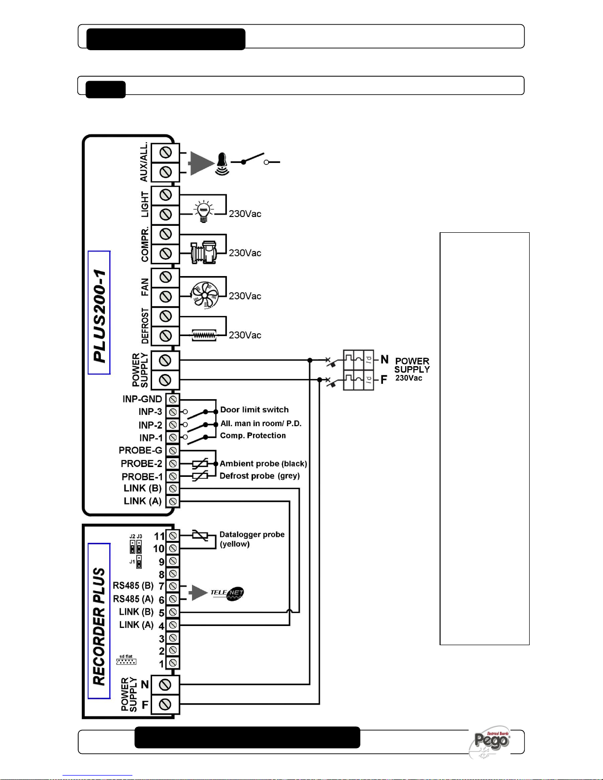
PLUS200 EXPERT
Pág. 38
MANUAL DE USO Y MANTENIMIENTO
USE AND MAINTENANCE MANUAL
Rev. 01-16
ESQUEMA DE CONEXIÓN 200P200EDL / 200P200EDL WIRING DIAGRAM
Salidas en tensión (230 V) excepto el contacto Aux/All.
Live outputs (230 V) excluding Aux/All contact.
Anexos / Appendices
PLUS200 EXPERT
cód.: 200P200EDL
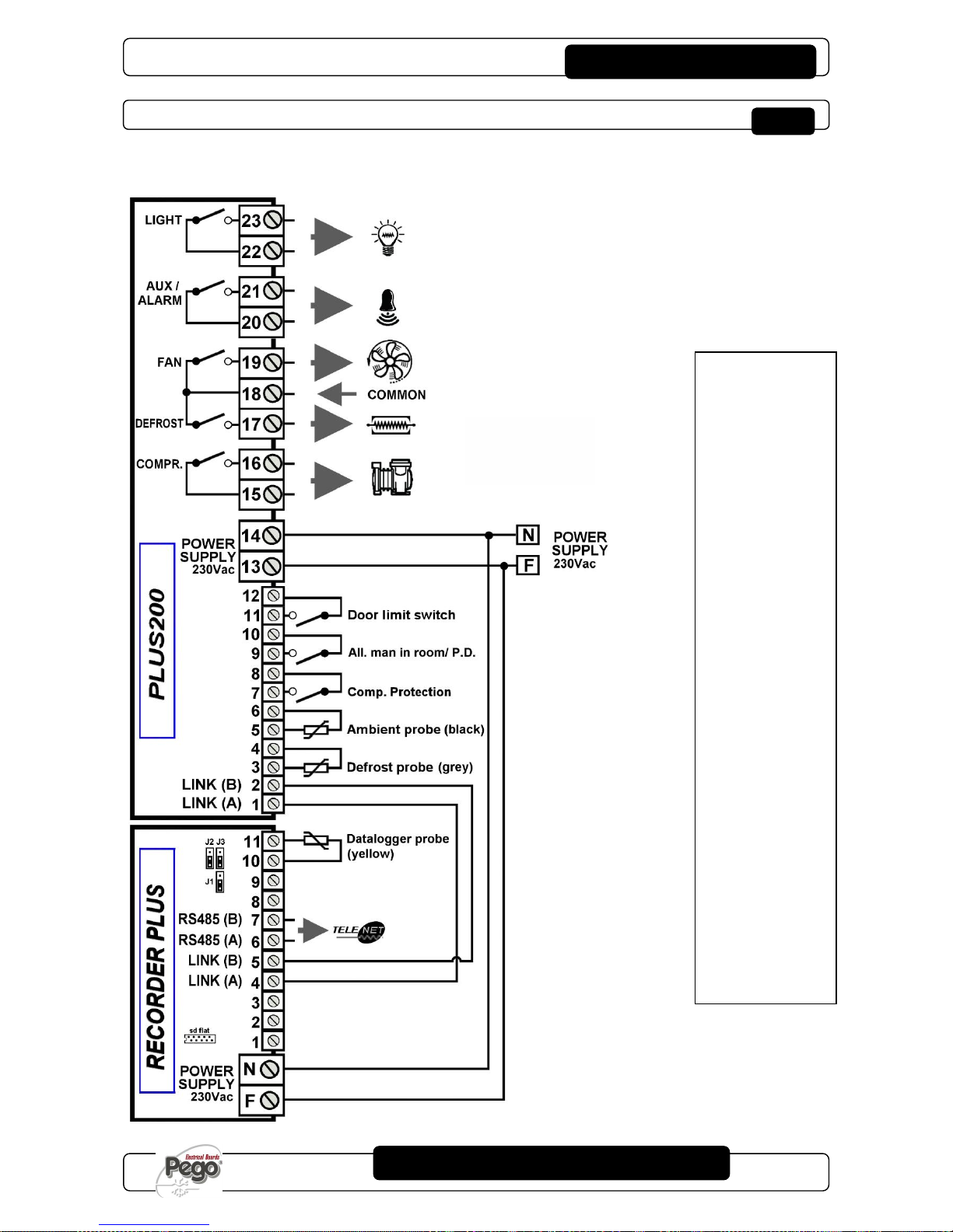
PLUS200 EXPERT
Pág. 39
MANUAL DE USO Y MANTENIMIENTO
USE AND MAINTENANCE MANUAL
Rev. 01-16
ESQUEMA DE CONEXIÓN 200P200EDLCR / 200P200EDL WIRING DIAGRAM
Salidas de contactos libres (contactos libres de tensión)
Clean-contact outputs. (non-powered contact)
PLUS200 EXPERT CR
cód.: 200P200EDLCR
Anexos / Appendices

PLUS200 EXPERT
Pág. 40
MANUAL DE USO Y MANTENIMIENTO
USE AND MAINTENANCE MANUAL
Rev. 01-16
ESQUEMA DE CONEXIÓN 200P200EDLCR2 / 200P200EDLCR2 WIRING DIAGRAM
Salidas de contactos libres (contactos libres de tensión)
Clean-contact outputs. (non-powered contact)
Anexos / Appendices
PLUS200 EXPERT CR2
code: 200P200EDLCR2
PLUS200 EXPERT
Pág. 41
MANUAL DE USO Y MANTENIMIENTO
USE AND MAINTENANCE MANUAL
Rev. 01-16
DESPIECE / EXPLODED DIAGRAM AND PARTS LIST
LEYENDA / KEY
REF.
DESCRIPCIÓN
DESCRIPTION
1
CAJA POSTERIOR DE ABS
BOX REAR IN ABS
2
CAJA FRONTAL DE ABS
BOX FRONT IN ABS
3
TAPA FRONTAL DE
POLICARBONATO TRANSPARENTE
FRONT COVER IN TRANSPARENT
POLYCARBONATE
4
BISAGRAS DE APERTURA CAJA FRONTAL
BOX FRONT OPENING HINGE
5
TORNILLOS DE CIERRE DE LA CAJA
BOX CLOSURE SCREWS
6
TORNILLOS DE FIJACIÓN DE LAS TARJETAS
BOARD FIXING SCREWS
7
MAGNETOTÉRMICO DIFERENCIAL DE
PROTECCIÓN / SECCIONAMIENTO POTENCIA
MAGNETO-THERMAL CUT-OUT / POWER
BREAKER
8
TARJETA CPU PLUS200
CPU BOARD
9
COBERTURA DE POLICARBONATO PARA
TORNILLOS
POLYCARBONATE SCREW COVER
10
BORNE PARA LAS CONEXIONES DE PUESTA A
TIERRA
TERMINAL FOR EARTH CONNECTIONS
11
TARJETA RECORDER PLUS
RECORDER PLUS BOARD
12
SLOT PARA CARD SECURE DIGITAL
SECURE DIGITAL SLOT
13
COBERTURA DE LA TARJETA ELECTRÓNICA
ELECTRONIC CARD COVER
Anexos / Appendices
PLUS200 EXPERT
Pág. 42
MANUAL DE USO Y MANTENIMIENTO
USE AND MAINTENANCE MANUAL
Rev. 01-16
NOTAS

PLUS200 EXPERT
Pág. 43
MANUAL DE USO Y MANTENIMIENTO
USE AND MAINTENANCE MANUAL
Rev. 01-16
NOTAS

PLUS200 EXPERT
Pág. 44
MANUAL DE USO Y MANTENIMIENTO
USE AND MAINTENANCE MANUAL
Rev. 01-16
PEGO S.r.l.
Via Piacentina 6/b
45030 OCCHIOBELLO –ROVIGOTel.: 0425 762906
Fax: 0425 762905
www.pego.it
e-mail: info@pego.it
Distribuidor / Dealer:
 Loading...