


REV. 01/04
User and maintenance manual
ELECTRICAL BOARDS FOR REFRIGERATING INSTALLATIONS
READ AND KEEP
REV. 01-19
ENG
VISION TOUCH PAN
ENGLISH
Rel. Software: VT_PAN_2_0_0_3

VISION TOUCH PAN
Pag. 2
USER AND MAINTENANCE MANUAL
Rev. 01-19
Thank you for choosing PEGO'S VISION TOUCH PAN controller.
Reading this manual thoroughly will guide you through proper installation and better use of
the various features. We therefore recommend keeping this manual near the controller to
make use of it during the device installation, configuration and use.
Waste disposal guidelines:
The Vision Touch controller consists of glass parts, plastic parts and metal parts.
With reference to the Directive 2012/19/UE of the European Parliament and of the Council
of 4 July 2012 and related national legislation, please note that:
A. There is the obligation not to dispose of WEEE as urban waste and to perform
separate collection of this waste.
B. Public or private waste collection facilities foreseen by local laws must be used to
dispose of the materials. It is also possible to give the device back to the distributor
at the end of its life when purchasing a new one.
C. This equipment can contain dangerous substances: improper use or incorrect waste
disposal could have negative effects on human health and on the environment.
D. The symbol (crossed-out waste bin on wheels) applied to the pack, product
and instructions indicates that the appliance was placed on the market after August
13, 2005, and must be disposed of separately.
E. In case of abusive disposal of electrical and electronic waste, there are sanctions
established by local standards in force concerning waste disposal.

VISION TOUCH PAN
Pag. 3
USER AND MAINTENANCE MANUAL
Rev. 01-19
INTRODUCTION
Page 5 1.1 General information
Page 6 1.2 Product identification codes
Page 7 1.3 Overall dimensions
Page 7 1.4 Identification data
Page 8 1.5 Technical features
INSTALLATION
Page 9 2.1 General rules for the installer
Page 9 2.2 Standard equipment for assembly and use
Page 10 2.3 Installation and assembly
ELECTRICAL CONNECTIONS
Page 12 3.1 Console / 100N MASTER3 power supply and connection
Page 14 3.2 Connection of digital outputs on 100N MASTER3
Page 15 3.3 Connection of digital inputs on 100N MASTER3
Page 16 3.4 Connection of analogue inputs on 100N MASTER3
Page 17 3.5 Connection of analogue outputs on 100N MASTER3
Page 17 3.6 Ethernet connection on Vision Touch
Page 18 3.7 Connection to RS-485 for TeleNET or Modbus- RTU
SWITCHING ON
Page 19 4.1 Commissioning
Page 20 4.2 Switch-on controller
USER INTERFACE
Page 21 5.1 Console functional zones
Page 22 5.2 Main display
Page 22 5.3 Status bar
Page 23 5.4 Button bar
Page 25 5.5 Gesture
HOME PAGES
Page 29 6.1 Manual mode: Selects manual mode and Temperature/Humidity Management
Page 32 6.2 Manual mode: Modify the Temperature/Humidity setpoint and fan speed
Page 34 6.3 Automatic programs Display, create, start and edit.
Page 36 6.4 Automatic programs: Description of the Program Steps
Page 37 6.5 Automatic programs: Add/Edit Program Steps
Page 44 6.6 Automatic programs: Automatic cycle
ACCESS LEVELS
Page 47 7.1 Access levels to parameters (User / installer)
Page 47 7.2 Lock screen and User / installer login
CHAPTER 1
CONTENTS
CHAPTER 2
CHAPTER 3
CHAPTER 4
CHAPTER 5
CHAPTER 6
CHAPTER 7

VISION TOUCH PAN
Pag. 4
USER AND MAINTENANCE MANUAL
Rev. 01-19
PARAMETERS
Page 48 8.1 Access to the “Parameters” menu
Page 49 8.2 Description of parameters setting page
Page 50 8.3 Parameters menu items list
Page 52 - 8.3.1 Process adjustment
Page 53 - 8.3.2 Defrost cycles
Page 55 - 8.3.3 Ventilation
Page 56 - 8.3.4 Air change
Page 56 - 8.3.5 Configure PAN
Page 57 - 8.3.6 Machine protection
Page 58 - 8.3.7 Probes calibration
Page 58 - 8.3.8 Configuration RS458
Page 59 - 8.3.9 Web server
Page 63 - 8.3.10 Mail
Page 64 - 8.3.11 PEGO humidifier
Page 65 - 8.3.12 Language
Page 66 - 8.3.13 Date and time
Page 67 - 8.3.14 General settings
Page 68 - 8.3.15 Software
Page 69 - 8.3.16 Info
Page 70 - 8.3.17 Password
Page 72 - 8.3.18 Test center
Page 76 - 8.3.19 Configure I/O
Page 81 - 8.3.20 I/O status
PROGRAM MANAGEMENT
Page 82 9.1 Program Management
DIAGNOSTICS
Page 83 10.1 Diagnostics
Page 85 10.2 Alarms management
Page 86 10.3 Pop-up management
WEB
SERVER
Page 87 11.1 Installation
Page 89 11.2 Web interface: user access
Page 90 11.3 Web interface: pages
OPERATION
Page 98 12.1 Cold/hot: preservation of ambient temperature
Page 99 12.2 Humidify/dehumidification: preservation of ambient humidity
Page 100 12.3 0-10V Proportional Humidifier management
Page 100 12.4 New software features
APPENDICES
Page 101 A.1 EU Declaration of Conformity
Page 102 A.2 Warranty terms
CHAPTER 8
CHAPTER 10
CHAPTER 12
CHAPTER 9
CHAPTER 11

VISION TOUCH PAN
Pag. 5
USER AND MAINTENANCE MANUAL
Rev. 01-19
GENERAL INFORMATION
DESCRIPTION:
VISION TOUCH PAN enables advanced control of retarding cells, cabinets or counters
with temperature and humidity control.
The system consists of the 100N MASTER3 unit, on which all the electrical connections
are made, and the VISION TOUCH PAN control console, equipped with 7'' TFT display
with capacitive touch screen combined with a highly advanced software and a highly user
friendly interface that allows easy use.
APPLICATIONS:
- Retarding cabinets, counters and cells for industrial and in-store bakeries and
confectioneries.
- Replacing other retarding controls on existing systems.
TECHNICAL SPECIFICATIONS FOR RETARDING:
- Hot manual mode (leavening)
- Cold manual mode (accumulation)
- Manages automatic retarding programs that can be customised, consisting of a
maximum of 9 steps that can be set (2 accumulation phases, 3 preservation phases, 3
leavening phases and 1 resting phase); the following is possible for each phase:
Enable its operation (with the exception of Preservation phase 3 that is always present);
Set the functions enabled in the phase (Cold , Hot , Humidify and Dehumidify );
Phase duration, Temperature setpoint and Humidity setpoint;
Select the evaporator fan speed and continuous fan forcing;
Switch to enable temperature threshold management, below which humidity control is
inhibited;
Switch to enable defrosting for the accumulation and preservation phases. (At the
beginning of the leavening phase, a defrosting phase is launched, if enabled, and this is
then inhibited during the leavening and resting phases);
Switch to enable the gradual increase to reach the Temperature setpoint (only for the
leavening phases).
- Possibility of enabling a warning for the end of program and oven advance ignition
command.
- Store up to 12 programs in the internal memory with the option of exporting them to a
USB or microSD.
- Diagram of the program in execution with progress display (completed phases, phases
in progress and phases yet to be executed) and a representation of the set values and
of all the remaining times.
- Temperature adjustment range: -45°C/+99°C; humidity adjustment range: 0-100 R.H.%
CHAPTER 1: INTRODUCTION
CHAP. 1 - Introduction

VISION TOUCH PAN
Pag. 6
USER AND MAINTENANCE MANUAL
Rev. 01-19
GENERAL CHARACTERISTICS OF THE CONTROLLER:
- 7'' TFT display with high resolution (800x480 WVGA), LED backlighting and capacitive
touch screen.
- Front with 1,1 mm chemically treated glass.
- Ability to reverse the viewing angle of the display to ensure the possibility of mounting
at any height.
- Devices: USB 2.0, microSD, RS485.
- Acoustic signals.
- IP65 frontal protection.
- High quality design and icons.
- Touch screen interface with gestures, for an even more intuitive control.
- Clock and calendar (RTC).
- Password function.
- Multilingual.
- Customizable user parameter menu (unused features can be hidden, simplifying the
menu).
- Contextual help in the parameter configuration menu.
- Software updating from microSD or USB.
- Ability to export and import parameters on USB or microSD media.
- Alarm history combined with popup warning messages.
- Advanced HACCP function with detailed memory of temperature / humidity alarms
triggered.
- "Test center" mode to check, in a simple and intuitive way, all the digital and analogical
inputs/outputs.
- RS485 serial connection with TeleNET or Modbus protocol which can be selected in
the parameters.
- Web server: control the Vision Touch from web browsers (controlled access).
- Proportional humidifier control with 0-10V analogue output.
- Automatic sending of e-mail in case of alarm.
PRODUCT IDENTIFICATION CODES
200VT100PAN1 - TOUCH electronic controller for retarding cells. It has
a stylish 7'' TFT display with capacitive touch screen
combined with a highly advanced software and a
highly user friendly interface that allows for easy use.
- 5m telephone cord included.
- 2 NTC probes (1x1.5 m + 1x3 m) included.
Humidity probe is separate.

VISION TOUCH PAN
Pag. 7
USER AND MAINTENANCE MANUAL
Rev. 01-19
OVERALL DIMENSIONS
Dimensions in mm:
IDENTIFICATION DATA
The device described in this manual has, on the side of 100N MASTER3 and on the back
of the VISION TOUCH PAN console, a plate bearing its identification data:
• Name of Manufacturer
• Code of the device
• Serial number of the device
• Date of manufacture
VISION TOUCH
100N MASTER3

VISION TOUCH PAN
Pag. 8
USER AND MAINTENANCE MANUAL
Rev. 01-19
TECHNICAL FEATURES
Power supply
Voltage
110 - 230 V~ 10% 50/60Hz
Max power consumption (electronic controller only)
~ 15 VA
Climatic conditions
Operating temperature
-5 ÷ +50°C
Storage temperature
-10 ÷ +70°C
Relative ambient humidity
Less than 90% RH
General features
Type of connectable probes (temperature)
NTC 10K 1%
Resolution (ambient temperature)
0.1 °C.
Precision of probe detection (ambient temperature)
± 0,5 °C
Reading range
-45 ÷ +99 °C
Humidity probe
analogue input 4-20 mA
Precision of humidity probe detection
see humidity probe features
Range of humidity probe detection
0-99 rH%
Output features
Description
Relay installed
Features of output board
Notes
Output 3-4
(30A AC1 relay)
30A 240V~ (AC1)
10A 240V~ (AC3) (2HP)
(100000 cycles)
All the outputs are
voltage-free
contacts
11 outputs from 5 to 26
(see connections diagram)
(16A AC1 relay)
16A 240V~ (AC1)
3A 240V~ (AC3)
Dimensional features
Dimensions 100N MASTER3
121.50 mm x 71 mm x 175 mm (HxDxL)
Dimensions VISION TOUCH PAN
151 mm x 44 mm x 191 mm (HxDxL)
Insulation and mechanical properties
Degree of protection of display
IP65
Material of box
Self-extinguishing ABS

VISION TOUCH PAN
Pag. 9
USER AND MAINTENANCE MANUAL
Rev. 01-19
GENERAL RULES FOR THE INSTALLER
1. If the program is used in applications with the risk of harming persons, machines or
materials, it must be coupled with auxiliary alarm devices.
2. The programmer must NOT be installed in environments with dangerous atmospheres
(flammable or explosive); it can only be connected to elements which operate in this
atmosphere by means of appropriate and suitable types of interface compliant with
safety standards in force.
3. Install the appliance in places which respect the degree of protection.
4. Avoid using multi-pole cables with conductors connected to inductive and power
conductors and signal conductors like probes and digital inputs.
5. Avoid housing power cables in the same conduits as signal cables (probes, digital or
analogue inputs, communication cables).
6. Minimize the length of the connecting cables to prevent these from coiling up and
adversely affecting the electronics through induction.
7. All the conductors of the cables must be of an appropriate size to withstand the required
load.
8. Place a general protection fuse upstream the electronic controller.
9. Provide a two-phase disconnecting switch compliant with foreseen safety requirements
(CE marked) to shut off the power supply upstream the controller. The switch must be
placed in the immediate vicinity of the regulator and must be easily reachable by the
operator.
10. Should the length of the probes need to be extended, it is necessary to use conductors
with an appropriate cross-section and however no less than 1mm². Extension or
shortening of the probes may alter the factory settings; use an external thermometer,
therefore, for testing and calibration.
11. When using the console at low temperatures there could be a visible slow down in the
response from the display; this can be considered normal.
STANDARD EQUIPMENT FOR ASSEMBLY AND USE
The VISION TOUCH PAN electronic controller is provided with the following for assembly
and use:
• 2 temperature probes;
• 1 plug telephone cable (5m);
• 1 user quick guide;
• 1 Vision Touch PAN (200VTOUCHPAN) console;
• 4 media for Vision Touch console;
• N° 1 100N MASTER3 (200100NMSTH3);
CHAPTER 2: INSTALLATION

VISION TOUCH PAN
Pag. 10
USER AND MAINTENANCE MANUAL
Rev. 01-19
INSTALLATION AND ASSEMBLY
Fig. 1: Install the 100N MASTER3
module on the DIN guide and
close the bottom clamps to hold
it in place.
Fig. 2: VISION TOUCH console drilling
template.
Fig. 3: Configure properly the side switch
(if present) to reverse the viewing
angle of the display. This allows you
to mount the VISION TOUCH at any
height.
When mounted in the low position,
rotate the display by 180 ° in order
to have the signal leds at the top.
177mm
136mm

VISION TOUCH PAN
Pag. 11
USER AND MAINTENANCE MANUAL
Rev. 01-19
Fig. 4: Fasten the VISION TOUCH console
by means of the four media to be
inserted in their specific seats.
Tighten each screw until the entire
border front of the console rests on
the panel.

VISION TOUCH PAN
Pag. 12
USER AND MAINTENANCE MANUAL
Rev. 01-19
Following are the electrical connections of the controller divided by type. The
configurations of the inputs and outputs shown below are set by default but can be
changed to suit your needs. The connection between the console and 100N MASTER3
has two possible variants based on the distance between the two components.
POWER SUPPLY AND CONNECTION CONSOLE / 100N MASTER3
1) Connection between the console and 100N MASTER3 with distance within
10m:
CHAPTER 3: ELECTRICAL CONNECTIONS
Power
supply
Connect the ground to the GND
terminal of M2 in the console
(functional ground).
This connection helps to limit the
effects of the electromagnetic
noise on the control system.
The earth connection must be
made in a manner consistent with
applicable regulations.
Connect the power to terminals 1
and 2 of 100N MASTER3.
Switching power supply:
115÷230Vac ±10% 50/60Hz
Demand: 20 VA max.
Use the supplied telephone cord
and connect the 8-pin Plugs to
J1in the console and to J1 in the
100N MASTER3 (it includes
communication and power).
Power
supply

VISION TOUCH PAN
Pag. 13
USER AND MAINTENANCE MANUAL
Rev. 01-19
2) Connection between the console and 100N MASTER3 with distance within
500m:
Power
supply
Connect the ground to the GND
terminal of M2 in the console
(functional ground).
This connection helps to limit the
effects of the electromagnetic
noise on the control system. The
ground connection must be made
in a manner consistent with
applicable regulations.
Connect the power to terminals 1
and 2 of 100N MASTER3.
Switching power supply:
115÷230Vac ±10% 50/60 Hz
Demand: 20 VA max.
Connect terminal (-) of M1 in the
console to terminal 45 of 100N
MASTER3 and term (+) of M1 in
the console to terminal 46 of
100N MASTER3.
Avoid coupling with power cables.
Connect terminal (1) of M2 in the
console to terminal 37 of 100N
MASTER3 and term (B) of M2 in
the console to terminal 38 of
100N MASTER3.
Connect the braid of the shielded
cable to the (GND) terminal of
M2in the console.
Use twisted cable suitable for the
transmission of RS485 signals
with minimum section of 0.5mm2
(e.g. Belden 8762 cable). Avoid
coupling with power cables.

VISION TOUCH PAN
Pag. 14
USER AND MAINTENANCE MANUAL
Rev. 01-19
DIGITAL OUTPUT CONNECTION ON 100N MASTER3
PIN
TERMINALS
DIGITAL
OUTPUT
DEFAULT SETTINGS
DIGITAL OUTPUTS
RELAY OUTPUT FEATURES
(Voltage-free contacts)
3-4
DO1
2 = Cold
(contact N.O)
Relay 30A 240V~ (AC1)
10A 240V~ (AC3) (2HP)
5-6
DO2
1 = Hot
(contact N.O)
Relay 16A 240V~ (AC1)
3A 240V~ (AC3)
7-8
DO3
3 = Fans high speed
(contact N.O)
Relay 16A 240V~ (AC1)
3A 240V~ (AC3)
9-10
DO4
4 = Fans low speed
(contact N.O)
Relay 16A 240V~ (AC1)
3A 240V~ (AC3)
11-12
DO5
5 = Humidify
(contact N.O)
Relay 16A 240V~ (AC1)
3A 240V~ (AC3)
13-14
DO6
6 = Dehumidify
(contact N.O)
Relay 16A 240V~ (AC1)
3A 240V~ (AC3)
15-16
DO7
7 = Light
(contact N.O)
Relay 16A 240V~ (AC1)
3A 240V~ (AC3)
25-26
DO8
8 = Air renewal
(contact N.O)
Relay 16A 240V~ (AC1)
3A 240V~ (AC3)
23-24
DO9
11 = Oven advance ignition
(contact N.O)
Relay 16A 240V~ (AC1)
3A 240V~ (AC3)
21-22
DO10
9 = Defrosting
(contact N.O)
Relay 16A 240V~ (AC1)
3A 240V~ (AC3)
19-20
DO11
10 = End recipe
(contact N.O)
Relay 16A 240V~ (AC1)
3A 240V~ (AC3)
17-18
DO12
12 = Alarm
(contact N.O)
Relay 16A 240V~ (AC1)
3A 240V~ (AC3)
POSSIBLE CONFIGURATIONS
DIGITAL OUTPUTS DO1÷DO12
Access menu:
Parameters > Configure I/O > Digital outputs
0 = Disabled
1 = Hot
2 = Cold
3 = Fan high speed
4 = Fan low speed
5 = Humidification
6 = Dehumidification
7 = Light
8 = Air Renewal
9 = Defrosting
10 = End recipe
11 = Oven advance ignition
12 = Alarm (only DO12)
Positive values = Contact N.O.
Negative values = Contact N.C.

VISION TOUCH PAN
Pag. 15
USER AND MAINTENANCE MANUAL
Rev. 01-19
DIGITAL INPUT CONNECTION ON 100N MASTER3
PIN
TERMINALS
DIGITAL
INPUT
DEFAULT SETTINGS DIGITAL INPUTS
(Use voltage-free contacts)
47-59
DI1
1 = Door switch (function Not active with contact N.O.)
48-59
DI2
2 = Alarm (function Not active with contact N.O.)
49-59
DI3
3 = Stand-by from remote (function Not active with contact N.O.)
50-59
DI4
4 = Disable hot (function Not active with contact N.O.)
51-59
DI5
5 = Disable humidity (function Not active with contact N.O.)
52-59
DI6
6 = Compressor protection (function Not active with contact N.O.)
53-59
DI7
7 = Humidifier alarm (function Not active with contact N.O.)
54-59
DI8
8 = Fans protection (function Not active with contact N.O.)
55-59
DI9
9 = Generic Warning 1 (function Not active with contact N.O.)
56-59
DI10
10 = Generic Warning 2 (function Not active with contact N.O.)
57-59
DI11
12 = High pressure (function Not active with contact N.O.)
58-59
DI12
13 = Low pressure (function Not active with contact N.O.)
POSSIBLE CONFIGURATIONS
DIGITAL INPUTS DI1÷DI12
Access menu:
Parameters > Configure I/O > Digital inputs
0 = Disabled
1 = Door switch
2 = Alarm
3 = Stand-by
4 = Disable hot
5 = Disable humidity
6 = Compressor protection
7 = Humidifier alarm
8 = Fans protection
9 = Generic Warning 1
10 = Generic Warning 2
11 = Generic Warning 3
12 = High pressure
13 = Low pressure
Positive values = Contact N.O.
Negative values = Contact N.C.

VISION TOUCH PAN
Pag. 16
USER AND MAINTENANCE MANUAL
Rev. 01-19
ANALOGUE INPUT CONNECTION ON 100N MASTER3
PIN
TERMINALS
DESCRIPT.
TERMINALS
TYPE OF
SIGNAL
ANALOGUE
INPUT
DEFAULT SETTINGS
ANALOGUE INPUTS
DEFAULT
SETTINGS BRIDGES
ON 100N MASTER3
27
RH
4-20mA
AI1
3 = Ambient humidity
probe
J11=2-3
J12=1-2
J13= open
28
V+
29
NTC
AI2
1 = Ambient temp.
J21=1-2
J22=2-3
J13= open
30 31
NTC
AI3
2 = Evaporator temp.
J31=1-2
J32=2-3
J33= open
32 33
NTC
AI4
0 = Disabled
J41=1-2
J42=2-3
J43= open
34 35
NTC
AI5
0 = Disabled
J51=1-2
J52=2-3
J53= open
36
POSSIBLE CONFIGURATIONS
ANALOGUE INPUTS AI1÷ AI5
Access menu:
Parameters >Configure I/O >Analogue inputs
0 = Disabled
1 = Ambient temperature (NTC)
2 = Evaporator temperature (NTC)
3 = Ambient humidity probe (4-20mA)
The selection of the desired function for each
analogue input is done by the configuration of the
dedicated parameter in the “ Parameters > Configure
I/O > analogue inputs” menu combined with the
correct setting of the Hardware configuration jumpers
on the 100N-MASTER3 under the removable front
cover (see the side image).
In particular, the configuration is as follows:
For NTC probes : J*1=1-2, J*2=2-3, J*3=open
For 4-20mA probes : J*1=2-3, J*2=1-2, J*3=open
*= number analogue input

VISION TOUCH PAN
Pag. 17
USER AND MAINTENANCE MANUAL
Rev. 01-19
ANALOGUE OUTPUT CONNECTION ON 100N MASTER3
PIN
TERMINALS
DESCRIPT.
TERMINALS
TYPE OF
SIGNAL
ANALOGUE
OUTPUT
DEFAULT SETTINGS
ANALOGUE OUTPUTS
41
Ref.
0-10V
AO1
1 = Speed of the evaporator fans
44
Gnd
42
Ref.
0-10V
AO2
0 = Disabled
44
Gnd
43
Ref.
0-10V
AO3
0 = Disabled
44
Gnd
ETHERNET CONNECTION ON VISION TOUCH
POSSIBLE CONFIGURATIONS
ANALOGUE OUTPUTS AO1÷ AO3
Access menu:
Parameters >Configure I/O >analogue outputs
0 = Disabled
1 = Speed of the evaporator fans
2 = Humidifier regulation
Connect the Ethernet cable with
RJ45 connector to the J3 input of the
Vision Touch console. Connect the
other end of the cable to the existing
LAN or to the PC.

VISION TOUCH PAN
Pag. 18
USER AND MAINTENANCE MANUAL
Rev. 01-19
CONNECTION TO RS-485 FOR TELENET OR MODBUS-RTU
1) Example of connection between the console and the Modbus line:
It is recommended to connect a resistance equal to 120 between A and B at the
beginning and end of the line in case of communication problems.
For a correct functioning the MASTER has to have a RS485 polarized.
Connect the earth to the GND
terminal of M3 in the console
(functional earth). This connection
helps to limit the effects of the
electromagnetic noise on the
control system.
The ground connection must be
made in a manner consistent with
applicable regulations.
Connect the terminal (A) of M3 in
the console to signal A of the
Modbus line and the terminal (B)
of M3 in the console to signal B of
the Modbus line. Connect the
braid of the shielded cable to the
terminal (GND) of M3 in the
console.
Use twisted cable suitable for the
transmission of RS485 signals with
minimum section of 0.5mm2 (e.g.
Belden 8762 cable).
Avoid coupling with power cables.

VISION TOUCH PAN
Pag. 19
USER AND MAINTENANCE MANUAL
Rev. 01-19
COMMISSIONING
When the controller is switched on for the first time, the "Language Selection" and "time
and date setting" pages of the system are displayed to facilitate the user in starting up the
controller. These settings can even be modified further on by means of the "Language"
and "Date and time" items within the "Parameters" menu.
CHAPTER 4: SWITCHING ON
Confirm the
settings by
pressing the
confirmation
button
Set the
language by
pressing these
buttons
Confirm the
settings by
pressing the
confirmation
Set the date
and time
by scrolling
your finger
over the digits
from the top
downwards
Automatic date
and time
synchronization
via the Web
(required ethernet
connection)

VISION TOUCH PAN
Pag. 20
USER AND MAINTENANCE MANUAL
Rev. 01-19
SWITCH-ON CONTROLLER
Every time the controller is switched on, an information pop-up is displayed with the
starting date and time, requesting the user to acquire the information by pressing "OK".
This allows to verify the return from an electrical blackout.
The start-up event is also memorized inside the "alarms" menu to make it possible to verify
this information over time.
Device power on
Begin: 18-12-2012 13:45:24
Information
acquisition
button
Controller
starting date
and time

VISION TOUCH PAN
Pag. 21
USER AND MAINTENANCE MANUAL
Rev. 01-19
This section illustrates the features and instructions for using the display, the light
indicators and the buttons making up the user interface of the VISION TOUCH PAN, and
therefore represent an essential requirement to correctly program and configure the
controller.
CONSOLE FUNCTIONAL ZONES
The display is divided into 3 main parts:
• Main display: interactively displays the various home pages and menu items.
• Status bar: it is divided into 3 parts and displays the following data:
- on the left: running status and name of program in progress.
- in the middle: description of current visualization of main display.
- on the right: current date/time, presence of USB key, or access as installer.
• Button bar: views the main operating buttons and their status.
At the bottom in the middle there are two LEDs:
Green LED: Flashing = controller in stand-by / On fixed = Controller powered
Red LED: Flashing = controller in Alarm
REV. 01/04
CHAPTER 5: USER INTERFACE
Main display
Status bar
Button bar
Indicator
LEDs

VISION TOUCH PAN
Pag. 22
USER AND MAINTENANCE MANUAL
Rev. 01-19
MAIN DISPLAY
The section of the main display views the work and setting pages based on the position
(for example Home, Configuration, phase). A detailed description of the various pages will
be made further on in this manual.
STATUS BAR
The Status Bar is in the lower part of the display (above the Button Bar, if applicable) and
displays some important information relating to the status of the device, such as the name
of the recipe in progress and the description of the currently displayed page. It is always
present except when, in some rare cases, it is temporarily hidden to fully exploit the
display.
Description of
current page, its
position and
total n. of
present pages.
Status (running
or stopped )
and name of
program in
progress.
USB Presence
Icon, SD
presence Icon,
User logged as
installer.
Current
date and time.

VISION TOUCH PAN
Pag. 23
USER AND MAINTENANCE MANUAL
Rev. 01-19
BUTTON BAR
The Button Bar is at the bottom of the display and views the main operating buttons and
their status. It is always present except when, in some rare cases, it is temporarily hidden
to fully exploit the display.
The buttons can have different shapes but always include an icon, a description and a
colour identifying the status.
In particular, the colour code of the buttons is the following:
BLUE:
Button which can be enabled
GREY:
Button not active (Disabled)
GREEN:
Button function activated or Confirmation button
YELLOW:
Cancel button
RED:
Alarm triggered indication or File elimination button
ORANGE:
Indication of alarm no longer triggered but yet to be acquired
Some buttons have delayed activation to avoid unintentional commands (see standby for
example). When pressed the progressive colour change is viewed until the function is
activated.

VISION TOUCH PAN
Pag. 24
USER AND MAINTENANCE MANUAL
Rev. 01-19
Description of buttons in Button Bar:
BACK:
Inside a menu or level: Go back to previous level or menu.
In a HOME page: Go back to the previous Home page.
If held for longer than 3 seconds: Go back to HOME1 page
PARAMETERS: Enter the parameter setting menu
ALARMS: Enter the alarm log menu
Red: Alarm triggered
Orange: Alarm over but yet to be acquired
Blue: No Alarm triggered or to be acquired
If the alarm log menu contains only items already acquired (shown in black) a waste bin will
appear inside this button indicating the possibility of cancelling the entire log.
HELP: Access the Help page that contains all the information about the
manufacturer/installer of the instrument. The data on this page may be modified by a user
who is logged in as an installer.
MANUAL AIR RENEWAL: Activates a manual air renewal or deactivates an automatic or
manual one in progress. (delayed start)
Green: Air renewal active
Blue: Air renewal not active
MANUAL DEFROST: Activates a manual defrost or deactivates an automatic or manual one
in progress. (delayed start)
Green: Defrost output active
Blue: Defrost output not active
MANUAL CELL LIGHT BUTTON: Manually activates/deactivates the cell light.
Green: Light active
Blue: Light not active
Flashing light icon: Indicates the forced activation of the light from the digital input of the door
switch open. With the open door digital input, the manual cell light, defrost, recovery and air
cycle buttons are deactivated.
STANDBY BUTTON: Activates/deactivates the standby status (delayed start)
Green: Standby active (System OFF)
Blue: Standby not active (System ON)
During standby, the program in progress keeps the count of the remaining time.
PROGRAM MANAGEMENT MANAGER BUTTON:
(Present in the Extended Button bar)
Once this is pressed, the program management screen appears, which allows data to be
imported from or exported to a USB or SD card.
EXTENDED BUTTON BAR OPENING BUTTON:
Opens or closes the EXTENDED BUTTON BAR that allows access to additional buttons.
Luce
Standby
Sbrina.
Allarmi
Indietro
Parametri
Manager
Help
Ric. aria

VISION TOUCH PAN
Pag. 25
USER AND MAINTENANCE MANUAL
Rev. 01-19
GESTURE
The Vision Touch, aside from normal pressing of keys, on some pages supports gestures
which allow the user a more natural and therefore simpler interaction.
Change Home Page: On one Home page, move your finger to the left or to the right to
pass from one Home page to the next one or to the previous one.
Note: it is also possible to move inside the Home pages by pressing the Back button.
The middle of the status bar has the description of the page currently displayed.
Change Page of a table or parameter list: Move your finger up or down to pass to the
next or previous data page.
The middle of the status bar has the description of the page currently displayed, its
position and the total number of pages displayable
Description of
current page,
its position
and total n. of
present pages
Description of
current page, its
position and
total n. of
present pages

VISION TOUCH PAN
Pag. 26
USER AND MAINTENANCE MANUAL
Rev. 01-19
Change parameters with roll selection: Move your finger up or down by one roll to
change its value. (Suggestion: move your finger starting from the outside of the roll and
pass through it completely).
If the value you are trying to set is not allowed and is not included in the range of the
variables, the background of the roll will turn red for an instant indicating that the action is
not allowed.
Changing parameters with a switch: Move your finger to the right or to the left to
activate or deactivate a switch.
Selection of parameters with Flags: press the flag to change the status or to select one
of the possible options.

VISION TOUCH PAN
Pag. 27
USER AND MAINTENANCE MANUAL
Rev. 01-19
"Edit" mode in Home 1 and 2 pages: When you are on one of the Home pages, touch
the screen at a point which is not a button for more than three straight seconds to enter
edit mode of the page itself. To exit this mode, press the "Back" button or wait for the
automatic exit after one minute of inactivity.
Edit Home 1 Page, Change Set Point with Wheel: Once you have entered edit mode on
Home 1, it is possible to change the humidity and temperature Set Points currently in use.
The variations are temporary and do not alter the preset program. Turn clockwise to
increase or anti-clockwise to decrease the value of the Wheel of the Set Point to be
modified or else act on the plus or minus buttons. Then confirm the new values by
pressing the green confirmation button.

VISION TOUCH PAN
Pag. 28
USER AND MAINTENANCE MANUAL
Rev. 01-19
The "Home" pages are the main interface of the controller from whence it is possible to
access the mostly used features. They are divided as follows:
MANUAL MODE (HOT OR COLD)
Display/modify the temperature and humidity
setpoints, modify the fan speed and select the
manual mode.
AUTOMATIC PROGRAMS
Complete management of programs (Recipes):
Display, create, edit, delete and load.
CURRENT PROGRAM (GRAPH)
Display program progress, modify the
temperature and humidity setpoints and view the
complete configuration of the current program.
CURRENT PROGRAM (SETPOINT)
Display/modify the temperature and humidity
setpoints and modify the fan speed of the current
phase.
CHAPTER 6: HOME PAGES

VISION TOUCH PAN
Pag. 29
USER AND MAINTENANCE MANUAL
Rev. 01-19
MANUAL MODE - Select the manual mode, Temperature/Humidity Management
The "MANUAL MODE" page allows the manual mode that is to be used (hot/cold) to be
selected, the Temperature and Humidity settings to be displayed and modified and access
to the recipes page by pressing the Select Program button.
• When in visualization, it is divided into 4 main sections:
• Buttons to select the manual mode.
• Temperature adjustment dial.
• Humidity adjustment dial.
• Multifunction data visualization dial.
• Button to access the automatic programs page.
Buttons to select the manual mode:
Cold manual mode. (button with delayed activation)
By activating this mode, the temperature setpoint in the StF
variable is first loaded. Only the cold call is controlled according to
the set temperature; the programmed defrost cycles are
performed if configured via the parameters. Nor the humidity or
the hot call is controlled in this mode.
Hot manual mode. (button with delayed activation)
By activating this mode, the temperature and humidity setpoints in
the StC and SUC variables are first loaded. The hot/cold calls are
controlled according to the set temperature and the humidification
/ dehumidification requests are controlled according to the set
humidity. The defrosting cycles are not controlled.
Temperature
Adjustment dial
Humidity
Adjustment dial
Buttons to select
the manual mode
Button to access
the automatic programs page
Multifunction data
visualization dial

VISION TOUCH PAN
Pag. 30
USER AND MAINTENANCE MANUAL
Rev. 01-19
Temperature adjustment dial: Displays all that regards temperature adjustment, in
particular:
• The temperature set point (can be modified by pressing the dial for 3 seconds).
• Adjustment probe temperature measurement.
• The status of the call (Cold / Hot / No call).
Humidity adjustment dial: Displays all that regards humidity adjustment, in particular:
• The humidity set point (can be modified by pressing the dial for 3 seconds).
• Adjustment probe humidity measurement.
• The status of the call (Humidify / Dehumidify / No call).
CHANGED
Status of call:
Cold Call
Hot Call
No Call
Adjustment probe
temperature
Temperature
Set Point
Temperature Set-Point
Bar-graph
Temperature value
Bar-graph
Notice of Set-point
changed
CHANGED
Status of the call:
Dehumidify Call
Humidify Call
No Call
Adjustment probe
humidity measurement
Humidity
Set Point
Humidity Set Point
Bar-graph
Humidity value
Bar-graph
Notice of Set-point
changed

VISION TOUCH PAN
Pag. 31
USER AND MAINTENANCE MANUAL
Rev. 01-19
Multifunction data visualization dial: it consists of two parts which, when touched,
cyclically alternate the data displayed. The following are the various screens and their
related meanings. Note: Some data is only viewed if the relative function is enabled in the
configuration parameters.
DIGITAL OUTPUT 1 STATUS
(Always visible)
Cold
Flashing= Standby
Dehumidify
for cold
Hot
Defrost
Flashing= Dripping
Humidify
Fans
low speed
Flashing= Standby
Dehumidify
separate
Fans
high speed
Flashing= Standby
Dehumidify
for heat
Fans
with 0-10V output
0-10V
DIGITAL OUTPUT 2 STATUS
(Always visible)
Light
Flashing= door switch
Stand-by
DIGITAL INPUT 1 STATUS
(Always visible)
Disable heat
remotely
Generic alarm
remotely
Disable humidity
remotely
Compressor
protection
Standby
remotely
Humidifier alarm
Door switch
Fans protection
DIGITAL INPUT 2 STATUS
(Always visible)
Generic Warning 1
Generic Warning 2
Generic Warning 3
EVAPORATOR TEMP. PROBE
MEASUREMENT / % HUMIDIFIER 0-10V
VALUE (visible if enabled)
This dial is only viewed if the variable “Parameters >
Defrosts > dE Evaporator probe enabled = 1” and if the
related analogue input is set.
% Humidifier 0-10V value:
This dial is only viewed if the related analogue output is set.

VISION TOUCH PAN
Pag. 32
USER AND MAINTENANCE MANUAL
Rev. 01-19
MANUAL MODE – Modify the Temperature/Humidity setpoint, the fan speed
“Modify setpoint” mode on the MANUAL MODE page:
Touch one of the adjustment dials on the screen (Temperature or humidity) for more than
three consecutive seconds.
Once you have entered the edit mode, it is possible to change the humidity and
temperature Set Points currently in use by rotating the Wheel clockwise to increase or anticlockwise to decrease the value of the Set Point to be modified. Otherwise you can press
the plus and minus buttons. Then confirm the new values by pressing the green "Confirm"
button or by pressing "Cancel" to go back to the display screen.
To exit this mode, you can also press the "Back" button or wait for the automatic exit after
one minute of inactivity.

VISION TOUCH PAN
Pag. 33
USER AND MAINTENANCE MANUAL
Rev. 01-19
Evaporator fan speed selection buttons:
Evaporator fans high speed.
Evaporator fans low speed.
Evaporator fans with 0-10V output.
This button is only displayed if the EFa parameter = 1.
Press + or - to increase or decrease the evaporator fan speed.
100 %
Evaporator fan speed
selection buttons

VISION TOUCH PAN
Pag. 34
USER AND MAINTENANCE MANUAL
Rev. 01-19
AUTOMATIC PROGRAMS – Display, create, start and edit.
Button to access the automatic programs display page:
Program selection:
Press this button to enter the automatic program
management and display page.
The "Program list" allows complete management of the programs (Recipes): view the list,
create, edit, delete and start the program.
The page is split into 2 main sections:
• Edit/start bar of an existing program.
• Bar to create a new program.
The controller will display the "Manual mode" page when the "Back" button is pressed or
automatically after one minute of inactivity.
Program
Edit / start bar
of an existing program
Bar to create
a new program
Navigation buttons to move
from one page to another of
the program list

VISION TOUCH PAN
Pag. 35
USER AND MAINTENANCE MANUAL
Rev. 01-19
Bar to create a new program: Allows a new program to be created; once pressed, it
prompts to enter the name using the keyboard and then the configuration of the phases
and the general settings.
The phase setting pages of a new program are the same as those used to Modify a
program. The internal memory can store up to 12 programs.
Edit/start bar of a program: Displays the name and the icon that identifies the program
and the preset time of the prepared product. There are also 2 buttons to:
• Start the program.
• Edit the program.
If the "Edit prepared product now" option has been enabled from the "Parameters >
Password > Configure user functions" menu, the following settings page will be displayed
every time a program is launched, through which the end time and date of the leavening
phase is set.
Button to create a new program
Preset day and time for the prepared
product
Program identification
icon
Program name
Program Edit button
Start program
Hour of prepared product.
Day of prepared product.

VISION TOUCH PAN
Pag. 36
USER AND MAINTENANCE MANUAL
Rev. 01-19
AUTOMATIC PROGRAMS - description of the Program Phases
There can be up to 9 phases in a program, split as follows:
- Accumulation 1 (Pre-cooling/chilling) [-18°C/-10°C]:
In this phase, the temperature is brought to a very low value to prepare the cell for the
product to be inserted. The cold accumulation reached allows the leavening process of
the food to be stopped immediately when entered.
- Accumulation 2 (stabilisation) [-6°C/-4°C]:
In this phase, a negative temperature is maintained in order to block the leavening
process and allow the core of the product to cool.
- Preservation 1, 2 and 3 (Preservation) [-2°C/+5°C and 70/80RH%]:
In these phases, the temperature is increased and the humidity is controlled to reach a
level that allows the product to be maintained as at the beginning of the leavening
phase. Preservation phase 3 is distinguished from the other 2 as it cannot be excluded
and its duration is automatically calculated to obtain the prepared product (the end of
program) on the date and at the time set by the operator.
- Leavening 1, 2 and 3 (Return, Pre-leavening, Leavening) [+8/+28°C and 75/85RH%]:
These steps allow the product to warm up gradually in order to leaven.
The product is ready to be cooked at the end of these phases. (End of program).
- Rest (Delayed baking) [+12/+14°C and 75/80RH%]:
This phase can be used once the product is completely leavened and baking is to be
delayed while maintaining the correct state of preservation.
Hereunder is the suggested default creation of a new program:
The created programs can be highly personalised and the following can be enabled for
each phase:
- Enable its operation (with the exception of Preservation phase 3 that is always present);
- set the functions enabled in the phase (Cold , Hot , Humidify and Dehumidify );
- Phase duration, Temperature setpoint and Humidity setpoint;
- Select the evaporator fan speed and continuous fan forcing;
- Switch to enable temperature threshold management, below which humidity control is
inhibited;
- Switch to enable defrosting for the accumulation and preservation phases. (At the
beginning of the leavening phase, a defrosting phase is launched, if enabled, and this is
then inhibited during the leavening and resting phases);
- Gradual increase to reach the Temperature setpoint (only for the leavening phases).
/ / /
/
Phase
Phase
Phase
Phase
/
Phase
Phase
Phase
Phase
-10.0°C
-5.0°C
+2.0°C
+2.0°C
+2.0°C
+10.0°C
+14.0°C
+27.0°C
+12.0°C
/ / 70RH%
70RH%
70RH%
80RH%
80RH%
80RH%
80RH%
1 hour
4 hours
1 hour
1 hour
automatic
2 hours
2 hours
2 hours
4 hours
Accumulati
on
1
Accumula
tion
2
Preservation
1
Preservation
2
Preservation
3
Leavening
1
Leavening
2
Leavening
3
Rest
PROGRAM END
Program duration time
PROGRAM START

VISION TOUCH PAN
Pag. 37
USER AND MAINTENANCE MANUAL
Rev. 01-19
AUTOMATIC PROGRAMS - Add/Edit Program Phases
The button appears when the program is stopped and the PROGRAM LIST is accessed.
Edit program:
Enters the program edit page.
Enabling the single phases.
Change the generic settings of
the program.
Change the settings of the enabled phases.
Edit

VISION TOUCH PAN
Pag. 38
USER AND MAINTENANCE MANUAL
Rev. 01-19
The buttons appear when the edit page of a recipe is accessed. These are overlapped
with the CONFIRM and CANCEL buttons if at least one configuration of the program is
edited.
Delete program.
Deletes the program from the memory of the device.
Copy program.
After having entered a new name, it saves a copy of the selected program.
By pressing the button on the left of the program icon at the top of the summary bar,
you enter the following program options configuration page.
General option configuration page of program 1/3:
The prepared product settings page is also available when the PLAY button is pressed to
start the program, if the 'Edit prepared product now' function is enabled, which can be
selected from the "Password" => "Configure user functions" submenu (installer login
required).
Cancella
Copia
Program generic settings.
Hour of prepared product.
Day of prepared product.

VISION TOUCH PAN
Pag. 39
USER AND MAINTENANCE MANUAL
Rev. 01-19
General option configuration page of program 2/3:
Note:
The automatic program is completed when all accumulation, preservation and leavening
phases have been performed, excluding the rest phase.
Notice (popup) at program end:
The user is informed of the end of a program
by means of a notice Pop-up.
(Press OK to acquire the message)
Switch on relay at program end:
A specific relay is activated when the program end notice pop-up is
present. By pressing OK in the Pop-up, the relay de-energises
and the pop-up closes.
Select icon:
This button accesses the database of
icons that can be used to identify a
program.

VISION TOUCH PAN
Pag. 40
USER AND MAINTENANCE MANUAL
Rev. 01-19
General option configuration page of program 3/3:
Defrosting when leavening begins:
if enabled, a defrosting process is performed at the beginning of
the leavening phase.
Oven advance ignition:
the switch enables the oven advance ignition control.
Configures the advance ignition (hours and minutes)
of the oven with respect to the end of the recipe.
If the “oven advance ignition” relay is enabled, it
will energise for 10 seconds.

VISION TOUCH PAN
Pag. 41
USER AND MAINTENANCE MANUAL
Rev. 01-19
Press the button in the bottom left corner of each phase to access the phase
configuration page.
Phase configuration page 1/2:
The following functions can be enabled in all the phases:
Hot
Cold
Humidify
Dehumidify
The Defrosting function can also be enabled in the ACCUMULATION and
PRESERVATION phases. Defrosting cannot be enabled in the other phases.
Confirm and cancel
modifications buttons
Name of
the selected phase
Phase period
(hh:mm)
Temperature
Set point (°C)
Humidity
Set point (%RH)
Buttons for moving between
configuration pages
Active functions
in this phase

VISION TOUCH PAN
Pag. 42
USER AND MAINTENANCE MANUAL
Rev. 01-19
Phase configuration page 2/2:
Temperature threshold
for humidity control:
enables the humidity control only
when the room temperature
exceeds this threshold. Disable
the switch to continuously control
the humidity.
The window will not be visible if
the humidify and dehumidify
functions are disabled during this
phase.
Evaporator fan speed selection in
selected phase.
If the 0-10V output is selected for fan speed
regulation (parameter EFa=1 in the Ventilation
menu present in the parameters) there is a
speed selection roll instead of these two flags
(20-100%)
Fans:
Fan start-up mode control.

VISION TOUCH PAN
Pag. 43
USER AND MAINTENANCE MANUAL
Rev. 01-19
Phase configuration page 3/3 (only for leavening):
An additional configuration page is present during the leavening phases, on which the
gradual setpoint increase function can be enabled for a temperature ramp to be obtained.
With this function active, the phase duration time becomes the time required to reach the
set temperature.
This function is useful to standardise the leavening process of products of different size
and type. It can be used to configure a leavening phase as a ‘wake up’ phase with the
"Varied progressive temp." option enabled and then a leavening phase that will maintain
the product at the leavening temperature for as long as is required.
When the "Varied progressive temperature" function is enabled, the set value appears
between the > < symbols under the setpoint, which changes progressively. If (CH) appears
at its side, it indicates the manual change in the setpoint with respect to the setting in the
program.
Set temperature
(°C)
Setpoint in
progress
Return Phase
Leavening Phase

VISION TOUCH PAN
Pag. 44
USER AND MAINTENANCE MANUAL
Rev. 01-19
AUTOMATIC PROGRAMS - Automatic cycle
The "automatic cycle" is displayed automatically after a program is started, if the prepared
product time is correct. At the end of the program or when the STOP button is pressed, the
"Manual mode" screen is automatically displayed.
The page is split into 2 main sections:
• Progress of the program: this section contains the progress graph of the temperature
setpoints; the phases that have already been performed and the current one are
coloured, whereas the ones left are in grey. The icon, name and time and date of the
prepared product are also indicated.
• Summary bar of the current phase: the current phase is indicated by an arrow.
Stop program:
Ends the current program and returns to the "Manual status" page.
Stop
Progress of the program.
Summary bar of the current phase:
contains the measured temperature and humidity values, the setpoints, the remaining time for the
current phase to end and the STOP button to stop the program. "CHANGED" appears if the current
values of the setpoints are different from those set in the program.

VISION TOUCH PAN
Pag. 45
USER AND MAINTENANCE MANUAL
Rev. 01-19
Summary bar of the current phase:
Tap the summary bar of the current phase to access the temperature and humidity
setpoint page.
"Edit setpoints" mode on the CURRENT PROGRAM (SETPOINT) page:
Touch one of the adjustment dials on the screen (temperature or humidity) for more than
three consecutive seconds. ''CHANGED'' appears in the dials if the current values of the
setpoints are different from those set in the program.
Press the "Graph" or "Back" button to return to the graph of the current program.
"Program configuration" mode on the CURRENT PROGRAM page:
Tap on the progress of the current program for more than three consecutive seconds.

VISION TOUCH PAN
Pag. 46
USER AND MAINTENANCE MANUAL
Rev. 01-19
At this point a graph with the trends of the temperature and humidity setpoints set in each
phase of the program will be displayed. It is possible to view the complete configuration of
a phase (and modify the setpoints, if the user is enabled), by pressing the button.
To exit this mode, you can press the "Back" button or wait for the automatic exit after one
minute of inactivity.

VISION TOUCH PAN
Pag. 47
USER AND MAINTENANCE MANUAL
Rev. 01-19
Access levels to parameters (User/ installer)
The controller has two access levels to the parameters and to the functions: “User” and
“Installer”. The default setting is User that has a parameter menu that can be customised
by the installer. Installer access is by logging in from the « Parameters > Password >
installer login » menu and inserting the assigned password.
PASSWORD SET BY DEFAULT:
Installer Password : 0100
The user logged in as installer is indicated on the Status bar with an open lock. Logout is
performed automatically after one minute of inactivity or manually from the « Parameters >
Password > Installer Logout» menu.
Lock screen and User / Installer login
If the « Lock screen with password » function is activated, access as an installer or as a
user is based on the entered password while the screen unlocks.
PASSWORDS SET BY DEFAULT:
User Password : 0200
Installer Password : 0100
CHAPTER 7: ACCESS LEVELS
Screen for entering access
password
By pressing the Unlock button, you reach the Password entry display to
unlock the screen.
Locked screen display
positioned in Button bar.
Open lock icon: User logged in as installer.

VISION TOUCH PAN
Pag. 48
USER AND MAINTENANCE MANUAL
Rev. 01-19
Access to Parameters menu
Press the "Parameters" button in the Button Bar to access the control parameters setting
menu.
PARAMETERS:
Enters the parameter setting menu
Each item of the parameters menu gathers a list of variables specific for the function
described in the menu and in some cases a further submenu.
The items present in the main branch are all displayed if you are logged in as "Installer",
while the items displayed under "User" depends on the configuration set in "parameters >
configure user level menu" visible only if logged in as Installer.
Parametri
CHAPTER 8: PARAMETERS
General settings
Date and time
Software
Info
Password
Test center
Defrost
Process regulation
Fans
Air change
Configure PAN
Machine protection
Communication RS485
Probes calibration
Web server
PEGO Humidifier
Language
Mail
I/O configure
I/O status

VISION TOUCH PAN
Pag. 49
USER AND MAINTENANCE MANUAL
Rev. 01-19
Description of parameter setting page
Press the "Parameters" button in the Button Bar to access the controller parameters
setting menu. Each sub-menu contains the name of the variables that can be set, a brief
description in the selected language and the currently set value.
Press the name of the variable to be set to access the relative modification page.
Detailed description, indicating
the range of values that the
parameter can take on
Modifiable parameter value.
In the event
of incorrect setting,
the error is signalled
Variable
name
d4 Defrost interval
d5 Maximum length of defrost
d6 End of defrost setpoint
d7 Dripping duration
dF1 Defrost times programming
dF2 Defrost times programming
Current value
Variable name
Variable description

VISION TOUCH PAN
Pag. 50
USER AND MAINTENANCE MANUAL
Rev. 01-19
List of parameter menu items
Listed below is the complete list of items displayed in the “Parameters” menu:
Nome
Symbol
General description
Chapter
Process
regulation
General process parameters
(differential and neutral area settings)
8.3.1
Defrosts
Defrosting, dripping, evaporator presence settings
8.3.2
Fans
Fans activation and relative speed settings, 0-10 V
outlet setting
8.3.3
Air change
Air change time setting (up to 6)
8.3.4
Configure PAN
PAN mode setting
(Humidification/dehumidification management)
8.3.5
Machine
protection
System protection parameters: compressor
management, limits for set-points, dehumidification
limit time
8.3.6
Probe
calibration
Correction of temperature/humidity probes, etc.
values
8.3.7
RS485
communication
Configuration of RS485 serial communication
8.3.8
Web server
Configurazione Web server
8.3.9
Mail
E-mail configuration
8.3.10
PEGO
humidifier
Enabling communication with a PEGO humidifier
8.3.11
Language
Control unit language setting
8.3.12
Date and time
Date and time settings
(not accessible while a program is running)
8.3.13
General settings
Contrast, brightness and sound alarms setting
8.3.14

VISION TOUCH PAN
Pag. 51
USER AND MAINTENANCE MANUAL
Rev. 01-19
Software
Management of control software reset and update,
device parameters export/import from USB/SD
8.3.15
Info
VISION TOUCH PAN device information
(software version, memory occupied)
8.3.16
Password
Management of protection level:
user/installer access, menu configuration
8.3.17
Test center
Digital/analogue inputs/outputs test, touchscreen
interface operation test
8.3.18
Configure I/O
Configuration of functions associated to
digital/analogue inputs/outputs
8.3.19
I/O Status
Verify the status of the digital and analogue
inputs/outputs
8.3.20

VISION TOUCH PAN
Pag. 52
USER AND MAINTENANCE MANUAL
Rev. 01-19
Process adjustment
“Process adjustment” allows setting the differentials and the temperature and humidity
neutral area of the PAN.
The “Process adjustment” menu can be accessed from the main Configuration page
(“Parameters” Button). The display of this item can be set in the “Password” sub-menu =>
“Configure user level menu” and by selecting the “Process adjustment” item (installer login
required).
VARIABLES
MEANING
VALUES
DEFAULT
dtC
HOT temperature differential with reference to main SET-
POINT. It is expressed in absolute value and it defines the
temperature hysteresis for HOT referred to the temperature
SET-POINT.
(dnC+0,2) ÷ 10,0 °C
2,0 °C
dtF
COLD temperature differential with reference to main
SET-POINT. It is expressed in absolute value and it defines
the temperature hysteresis for COLD referred to the
temperature SET-POINT.
(dnF+0,2) ÷ 10,0 °C
2,0 °C
dnC
Neutral hot zone Neutral temperature zone refers to the
main setpoint. Hot and cold are not activated in a neutral
zone. It refers to the lower part (hot) in relation to the
temperature setpoint.
0,0 ÷ (dtC-0,2) °C
0,0 °C
dnF
Neutral cold zone Neutral temperature zone refers to the
main setpoint. Cold and hot are not activated in a neutral
zone. It refers to the upper part (cold) in relation to the
temperature setpoint.
0,0 ÷ (dtF-0,2) °C
0,0 °C
dUU
HUMIDIFICATION differential with reference to humidity
SET-POINT. It is expressed in absolute value and it defines
the humidification hysteresis referred to the humidity SETPOINT.
(dnU+1) ÷ 10 rH%
5 rH%
dUd
DEHUMIDIFICATION differential with reference to humidity
SET-POINT. It is expressed in absolute value and it defines
the dehumidification hysteresis referred to the humidity SETPOINT.
(dnd+1) ÷ 10 rH%
5 rH%
dnU
NEUTRAL humidification zone with reference to the main
SETPOINT. Humidification and dehumidification are not
activated in a neutral zone. This includes the lower part
(humidification) in relation to the humidity SETPOINT.
0 ÷ (dUU-1) rH%
0 rH%
dnd
NEUTRAL dehumidification zone with reference to the
main SETPOINT. Humidification and dehumidification are
not activated in a neutral zone. This includes the upper part
(dehumidification) in relation to the humidity SETPOINT.
0 ÷ (dUd-1) rH%
0 rH%
StC
Temperature setpoint (hot manual mode)
When you activate the "hot manual mode", this value is
loaded into the temperature setpoint.
LSh ÷ HSh °C
27,0 °C
SUC
Humidity setpoint (hot manual mode)
When you activate the "hot manual mode", this value is
loaded into the humidity setpoint.
0 ÷ 100 rH%
80 rH%
StF
Temperature setpoint (cold manual mode)
When you activate the "cold manual mode", this value is
loaded into the temperature setpoint.
LSc ÷ HSc °C
-5,0 °C
Process regulation

VISION TOUCH PAN
Pag. 53
USER AND MAINTENANCE MANUAL
Rev. 01-19
Defrosts
Defrosts are managed with the parameters d4, d5, d6, d7, F5 which define their intervals,
the maximum duration, the defrost end temperature, dripping and fan stopping. To switch
defrost on manually, just press the “Defrost” button. Defrosting will not be activated if the
defrost end temperature (d6) is set lower than the temperature detected by the evaporator
probe. Defrosting will end when the defrost end temperature (d6) or the maximum defrost
period (d5) is reached.
The “Defrost cycles” menu can be accessed from the main Configuration page
(“Parameters” Button). The display of this item can be set in the “Password” sub-menu =>
“Configure user level menu” and by selecting the “Defrosting cycles” item (installer login
required).
Hot gas defrost
Set parameter d1 = 1 or 2 for managing cycle inversion defrosting.
The compressor relay and the defrosting relay are activated for the entire defrosting
phase.
If d1=2, the defrosting outlet stays active during the dripping stage to manage the bowl
resistances.
VARIABLES
MEANING
VALUES
DEFAULT
d4
Defrost interval (hours).
If d4=ON one must set the cyclic defrosting interval.
1 ÷ 24 ore
OFF
d5
Maximum defrost period (minutes)
1 ÷ 60 min
10 min
d6
Defrost end Set-point.
Defrosting is not carried out if the temperature
detected by the defrost probe is higher than the
value d6 (If the probe is faulty, the frosting is timed).
-35 ÷ 45 °C
15°C
d7
Dripping period (minutes)
At the end of defrosting, the compressor and fans
remain stopped for the set time d7, the defrost icon
flashes.
0 ÷ 10 min
0 min
dE
Evaporator probe exclusion
0 = probe absent
1 = probe present
1
d1
Type of defrost
Cycle inversion (hot gas) or resistance. With hot gas
the compressor output is also activated.
0 = resistance
1 = hot gas (defrosting outlet
off during dripping)
2 = hot gas (defrosting outlet
on during dripping, to
manage bowl resistances)
0
d9
Enabling defrosting in the cold manual mode
0 = disabled
1 = enabled
1
Defrost

VISION TOUCH PAN
Pag. 54
USER AND MAINTENANCE MANUAL
Rev. 01-19
For the correct management of the plant, it will be the responsibility of the installer to use
the defrost output, that must allow the opening of the cycle inversion electrovalve and the
closing of the liquid electrovalve.
For the capillary plants (without thermostatic valve) it is sufficient to control the cycle
inversion electrovalve using the defrosting relay control.
Ventilation
The parameters of the Ventilation menu allow to set the management of the fans in the
various operating modes. The “Ventilation” menu can be accessed from the main
Configuration page (“Parameters” Button). The display of this item can be set in the
“Password” sub-menu => “Configure user level menu” and by selecting the “Ventilation”
item (installer login required).
VARIABLES
MEANING
VALUES
DEFAULT
F5
Fan pause after defrost (minutes)
Allows to keep the fans stopped for a time F5 after dripping.
This time starts counting from the end of dripping. If dripping is
not set, at the end of defrost the fans pause immediately.
0 ÷ 10 min
0 min
F3c
Fan status when cold, hot, humidification and
dehumidification are stopped (Cold manual mode)
0 = Fans running
constantly
1 = Fans off if cold, hot,
humidification and
dehumidification off
1
F3h
Fan status when cold, hot, humidification and
dehumidification are stopped (Hot manual mode)
0 = Fans running
constantly
1 = Fans off if cold, hot,
humidification and
dehumidification off
0
F4
Fan pause during defrost
0 = Fans running during
defrost
1 = Fans not running
during defrost
1
F6
Evaporator fans activation for air circulation.
The fans are activated for a time defined by F7 if they were
not switched on for the time F6.
If the time of activation coincides with the defrost phase, it
waits for the end of defrost.
The fan speed (high/low) is the same as that selected for the
phase in progress.
OFF / 1 ÷ 240 min
OFF
F7
Evaporator fans activation period for air circulation.
Time fans running for air circulation (F6).
0 ÷ 240 sec
10 sec
F8
Fan speed. The value of this variable changes based on the
setting made in the last phase of a program carried out.
0 = High speed
1 = Low speed
0
EFa
Enables 0-10V output for fan speed control
The digital outputs high and low fan speed becomes the
enable. (Them Turned on if the 0-10V output higher than 0V)
0 = disabled
1 = enabled
0
Fs
Fan speed (percentage) when EFa=1.
The value of this variable changes based on the setting made
in the last phase of a program carried out.
20 ÷ 100 %
100%
Fans

VISION TOUCH PAN
Pag. 55
USER AND MAINTENANCE MANUAL
Rev. 01-19
Fst
FAN blocking TEMPERATURE
The fans do not switch on if the value of the temperature read
by the evaporator probe is higher than the value of this
parameter. The block is deactivated when the evaporator probe
is disabled or presents an error, in hot manual mode, when
recipe in progress in phases other than accumulation and
preservation.
-45,0 ÷ 99,0 °C
+99,0 °C
Fd
Differential for Fst
1,0 ÷ 10,0°C
2,0 °C
Fdo
Fan off delay after deactivating the hot output. It has priority
over standby, switch-port and defrost.
0 ÷ 600 sec
0 sec

VISION TOUCH PAN
Pag. 56
USER AND MAINTENANCE MANUAL
Rev. 01-19
Air change
The air changes can be enabled with parameter rA. Cyclical air exchange cycles, which
can be set using the rA parameter, can be performed. The duration of the air change is
defined by parameter drA. During air change, hot, cold, humidity and dehumidification do
not activate. It is possible, at any time, to force an air change with the “Air cycle” button.
The “Air change” menu can be accessed from the main Configuration page (“Parameters”
Button). The display of this item can be set in the “Password” sub-menu => “Configure
user level menu” and by selecting the “Air change” item (installer login required).
Configure PAN
“Configure PAN” allows to select which functions of the PAN control unit are enabled; it
particularly allows the humidity and heat control to be enabled/disabled.
The “Configure PAN” menu can be accessed from the main Configuration page
(“Parameters” Button). The display of this item can be set in the “Password” sub-menu =>
“Configure user level menu” and by selecting the “Configure PAN” item (installer login
required).
VARIABLES
MEANING
VALUES
DEFAULT
drA
Air change period.
1 ÷ 10 min
6
rA
Air change interval
00:01 ÷ 24:00
OFF
VARIABLES
MEANING
VALUES
DEFAULT
dEU
Dehumidification mode selection.
Separate dehumidification calls hot and
cold only for temperature.
0 = cooling
1 = heating
2 = separate dehumidification
3 = separate dehumidification and
active when cold output is off
0
EnU
Humidification enabling
0 = disabled 1 = enabled
1
End
Dehumidification enabling
0 = disabled 1 = enabled
1
EnH
Hot enabling
0 = hot disabled 1 = hot enabled
1
EnC
Cold enabling
0 = cold disabled 1 = cold enabled
1
Hr
Humidity management
Hr = 0 humidity management
disabled.
The humidity probe can be connected
without error on the display.
Hr = 1 humidity management enabled.
1
HmV
Minimum value of the humidifier
regulation analogue output.
0 ÷ +99 Rh%
20 Rh%
Air change
Configure PAN

VISION TOUCH PAN
Pag. 57
USER AND MAINTENANCE MANUAL
Rev. 01-19
Machine protection
“Machine protection” contains the safety parameters to manage the system. One can set
the minimum interval between compressor activations, the dehumidification limit time and
which action must be performed in the event the dehumidification limit time Timeout
intervenes.
The “Machine protection” menu can be accessed from the main Configuration page
(“Parameters” Button). The display of this item can be set in the “Password” sub-menu =>
“Configure user level menu” and by selecting the “Machine protection” item (installer login
required).
VARIABLES
MEANING
VALUES
DEFAULT
C1
Minimum time between shutdown and subsequent switchon of compressor. It also stops the fans if they are not active
for other functions.
0...15 min
0
LSh
Minimum value that can be attributed to the hot manual
mode temperature setpoint
-45,0 ÷ HSh °C
-45,0°C
HSh
Maximum value that can be attributed to the hot manual
mode temperature setpoint
LSh ÷ +99,0 °C
+99,0°C
LSc
Minimum value that can be attributed to the cold manual
mode temperature setpoint
-45,0 ÷ HSc °C
-45,0°C
HSc
Maximum value that can be attributed to the cold manual
mode temperature setpoint
LSc ÷ +99,0 °C
+99,0°C
btF
Temperature differential with reference to Set-point for COLD
BLOCK.
This is the SET-btF limit below which the cold and
dehumidification call relays are disabled.
The block function remains active until the set-point is reached.
OFF / 1 ÷ 20 °C
OFF
btC
Temperature differential with reference to Set-point for HOT
BLOCK.
This is the SET-btF limit below which the hot, humidification and
dehumidification call relays are disabled.
The block function remains active until the set-point is reached.
OFF / 1 ÷ 20 °C
OFF
dEt
DEHUMIDIFICATION time limit.
The Ed alarm is triggered if the dehumidification request is not
met (SET humidity reached) within the time (dEt). The count
starts at each new dehumidification demand.
OFF / 1 ÷ 240 min
OFF
Lt1
Minimum setpoint (accumulation)
-45,0 ÷ Ht1 °C
-20,0 °C
Ht1
Maximum setpoint (accumulation)
Lt1 ÷ 99,0 °C
0,0 °C
Lt2
Minimum setpoint (preservation)
-45,0 ÷ Ht2 °C
-15,0 °C
Ht2
Maximum setpoint (preservation)
Lt2 ÷ 99,0 °C
20,0 °C
Lt3
Minimum setpoint (leavening)
-45,0 ÷ Ht3 °C
10,0 °C
Ht3
Maximum setpoint (leavening)
Lt3 ÷ 99,0 °C
99,0 °C
Lt4
Minimum setpoint (rest)
-45,0 ÷ Ht4 °C
0,0 °C
Ht4
Maximum setpoint (rest)
Lt4 ÷ 99,0 °C
99,0 °C
Machine protection

VISION TOUCH PAN
Pag. 58
USER AND MAINTENANCE MANUAL
Rev. 01-19
Probe calibration
The “Probes calibration” menu allows to correct the value measured by the room/outside
temperature and humidity probes and to correct the value measured by the evaporator
probe. The menu can be accessed from the main Configuration page (“Parameters”
Button). The display of this item can be set in the “Password” sub-menu => “Configure
user level menu” and by selecting the “Probes calibration” item (installer login required).
RS485 communication
The “RS485 communication” menu allows to set the serial communication configuration.
The menu can be accessed from the main Configuration page (“Parameters” Button). The
display of this item can be set in the “Password” sub-menu => “Configure user level menu”
and by selecting the “RS485 communication” item (installer login required).
In the event of Ser=0 (Telenet), the Vision Touch responds as a TWMT instrument (room
temperature probe measurement) to address Ad and as a TWMUR instrument (room
humidity probe measurement) to address Ad+1.
VARIABLES
MEANING
VALUES
DEFAULT
Ad
Network address for connection to TeleNET or
Modbus supervision system.
0 ÷ 31 (Ser=0)
1 ÷ 247 (Ser=1)
1
Ser
RS-485 communication protocol
0 = TeleNET protocol
1 = Modbus-RTU protocol
0 ÷ 1
0
Bdr
Modbus baudrate
0 = 300 baud 5 = 9600 baud
1 = 600 baud 6 = 14400 baud
2 = 1200 baud 7 = 19200 baud
3 = 2400 baud 8 = 38400 baud
4 = 4800 baud
0 ÷ 10
5
Prt
Modbus parity control configuration.
0 = none parity
1 = even parity
2 = odd parity
0 ÷ 2
0
VARIABLES
MEANING
VALUES
DEFAULT
Cat
Ambient probe value correction
-10,0 ÷ +10,0 °C
0,0
CaU
Humidity probe value correction
-20 ÷ +20 Rh%
0
CaE
Evaporator probe value correction
-10,0 ÷ +10,0 °C
0,0
Probe calibration
RS485 communication

VISION TOUCH PAN
Pag. 59
USER AND MAINTENANCE MANUAL
Rev. 01-19
Web server
The "Web server" menu allows setting the Web server configuration. This menu is
accessible from the Main Configuration page (“Parameters” Button). The visibility of this
item can be set in the submenu "Password" => “Configure user level menu” and by
selecting the “Web server” item (installer login required)..
Web server
Settings
User name
Command enable
Info
Setting up your username for login
from the web
Basic configuration of Web server
(IP, Netmask, Gateway, DHCP)
Enable the change of parameters /
controls from web
“Info” checks the current Web
server setting (IP, MAC, etc.)

VISION TOUCH PAN
Pag. 60
USER AND MAINTENANCE MANUAL
Rev. 01-19
Settings page
- DHCP: enable / disable configuration request to the DHCP server. If enabled, the IP
address associated with Vision Touch is assigned by the DHCP server (if it is present on
the local network). If no assignment is made, the touch maintains the default configuration:
IP: 169.254.254.1 Gateway: 0.0.0.0
Netmask: 255.255.0.0 Port: 80
To check the configuration assigned by DHCP, see the "Info" page in the “Web server”
menu.
- Configure IP address / Netmask / Gateway: allow the setting of IP address / Netmask /
Gateway if DHCP is not used (for example in static IP setting).
- Configure Port: allows you to change the access port of the Web Server. In case of
connection of multiple Vision Touch on the same local network, set the NAT of the router
by associating local IP/port with public IP/port.
Warning: changing the port requires restarting the Vision Touch.
Example:
Enable / disable DHCP
Configure IP address
Configure Netmask
Configure Gateway
Changes are applied when the
“Confirm” button is pressed
ROUTER
(NAT)
Vision Touch 1
192.168.0.10
Port 80
Vision Touch 2
192.168.0.11
Port 8081
WEB
request:
http://94.138.43.134:8081/
Configure Port

VISION TOUCH PAN
Pag. 61
USER AND MAINTENANCE MANUAL
Rev. 01-19
The page “User name” allows configuring the Username to be used during login on the
Vision touch Web page (the password coincides with the Vision Touch Installer password).
Browser Web
Username Web
(default: adminlogin)
Password
(default: 100)

VISION TOUCH PAN
Pag. 62
USER AND MAINTENANCE MANUAL
Rev. 01-19
- Command enable page
The Wce parameter allows enabling or disabling commands and edits parameters from the
Web page, regardless of the type of user (user or admin) that accesses the Web page.
- Info page
The "Info Page" allows checking the current Web configuration of the Vision Touch PAN.
DHCP: DHCP assignment status
Host: name used in the web browser address bar (linked to the serial number)
IP / Netmask / Gateway: current configuration (set either locally or by DHCP)
MAC: unique physical address associated with Vision Touch
User name: Web user name
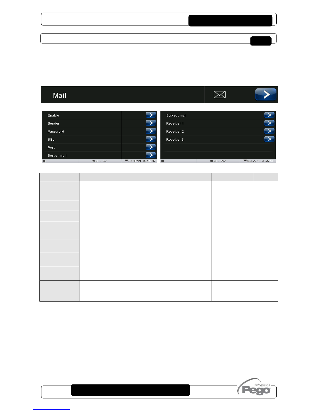
VISION TOUCH PAN
Pag. 63
USER AND MAINTENANCE MANUAL
Rev. 01-19
Mail
The “Mail” menu allows setting the alarm mail configuration. The menu can be accessed
from the main Configuration page (“Parameters” Button). The display of this item can be
set in the “Password” sub-menu => “Configure user level menu” and by selecting the “Mail”
item (installer login required).
VARIABLES
MEANING
VALUES
DEFAULT
Enable
Enable sending of mails in case of alarm. If configured as
“Test Mail” it sends a test mail to all recipients.
0=Disabled
1=Enabled
2=Test mail
0
Sender
Sender e-mail configuration (e.g. xxxxx@yyy.zz)
Text
Password
Sender e-mail password configuration
Text
SSL
Enable secure communication with the mail server
0= Disabled
1 = Enabled
1
Port
Mail port number (e.g. port 465 for SSL connection, port 25
for non-SSL connection.)
0 … 999
465
Server mail
Outgoing mail server (e.g. smtp.xxx.zz)
Text
Subject mail
Subject of mails (e.g. Cold room 1)
Text
Receiver 1
Receiver 2
Receiver 3
E-mail receivers (xxxxx@yyy.zz).
The alarm e-mail will be sent to all receivers.
Text
The Vision Touch sends an e-mail when an alarm occurs and when the alarm returns. The
email contains the following information:
- Alarm code and description
- date and time when the alarm started
- duration of the alarm (in case of alarm end email).

VISION TOUCH PAN
Pag. 64
USER AND MAINTENANCE MANUAL
Rev. 01-19
PEGO humidifier
CONNECTION
PIN TERMINALS (100NMASTER)
PIN TERMINALS (EASYSTEAM)
37
32
38
31
ENABLING
STATUS
PARAMETERS
PEGO humidifier
Enabling
Status
Parameters
Summary page of the status of inputs/outputs
of the humidifier.
The humidifier can be set to standby or the water can be
forced to drain on this page.
Enables communication with the PEGO humidifier.
Verify that jumper J2 inside the 100N MASTER is open and that the
humidifier has address Ad = 1.
Access to the read/edit
functions of the main
parameters

VISION TOUCH PAN
Pag. 65
USER AND MAINTENANCE MANUAL
Rev. 01-19
Language
The “Language” menu allows to change the control unit language. The menu can be
accessed from the main Configuration page (“Parameters” Button). The display of this item
can be set in the “Password” sub-menu => “Configure user level menu” and by selecting
the “Language” item (installer login required).
Language

VISION TOUCH PAN
Pag. 66
USER AND MAINTENANCE MANUAL
Rev. 01-19
Date and time
The “Date and time” menu allows to change the clock settings. One cannot access this
page while a program is running. The “Date and time” menu can be accessed from the
main Configuration page (“Parameters” Button). The display of this item can be set in the
“Password” sub-menu => “Configure user level menu” and by selecting the “Date and
time” item (installer login required).
If automatic synchronization via the Web is active, the control connects to an external
service that automatically determines the correct time zone and sets the date and time
considering any summer / winter time. The status of the last synchronization attempt
(referred to as "Last update") can be:
- None: no attempt to synchronize (for example at first power up);
- Error: the last synchronization attempt was not successful and therefore the control
keeps the date and time settings previously set;
- dd/mm/yyyy hh:mm:ss: date and time of the last synchronization correctly performed.
Date and time
Automatic date
and time
synchronization
via the Web
(required ethernet
connection)
Time settings
(hour : minute)
Date settings
Confirm
date and time
settings

VISION TOUCH PAN
Pag. 67
USER AND MAINTENANCE MANUAL
Rev. 01-19
General settings
The “General settings” menu allows to change the screen contrast, the brightness when
the screen is locked, the activation of the sound alarms and the activation of the
screensaver. “General settings” can be accessed from the main Configuration page
(“Parameters” Button). The display of this item can be set in the “Password” sub-menu =>
“Configure user level menu” and by selecting the “General settings” item (installer login
required).
We recommend setting the brightness to the minimum in order to maximize the display's
lifetime.
General settings
Lighting
when the
screen is
locked
Sound
On / Off
Screen
contrast
Contrast
Brightness
Screensaver
On / Off

VISION TOUCH PAN
Pag. 68
USER AND MAINTENANCE MANUAL
Rev. 01-19
Software
The “Software” menu allows to perform maintenance on the device software. The menu
can be accessed from the main Configuration page (“Parameters” Button). The display of
this item can be set in the “Password” sub-menu => “Configure user level menu” and by
selecting the “Software” item (installer login required).
Software updating procedure:
- Copy the update file "VT_PAN_#_#_#_#.pego" (the symbols # represent the progress
of the version) to an empty USB pen drive. Only the update file must be present in the
pen drive.
- Insert the USB pen drive in the USB1 port of the controller (the symbol of USB
inserted and acknowledged appears on the status bar).
- Press the "Update software" button.
- The device proceeds to update autonomously, performing the following steps (the
operation requires a few minutes): it exports the programs and configurations (if
applicable) > it deletes the internal memory and installs new software > it restores the
programs and configurations (if applicable) > it restarts the VISION TOUCH PAN.
Software
Aggiorna software
Ripristino valori di fabbrica
Clona configurazione macchina
Ripara EEPROM
Restore all default settings.
The execution of the program in progress is interrupted but the stored
programs are not deleted.
Exporting/importing the parameters
configuration from USB / SD
Repairing errors in the internal
memory of the control unit

VISION TOUCH PAN
Pag. 69
USER AND MAINTENANCE MANUAL
Rev. 01-19
ATTENTION: during the entire installation phase the controller must be kept powered
and the USB key must be left inserted. Failure to comply with this requirement could
entail PEGO S.r.l. having to restore the software.
The update finishes as soon as the controller goes back to the "HOME1" screen; at this
point you can remove the USB key and resume normal use.
The new Software version can be checked in the "Parameters" > "Info" menu under
"Application Version".
Info
The “Info” menu contains information relating to the software version installed and other
information about the device. The menu can be accessed from the main Configuration
page (“Parameters” Button).
Info

VISION TOUCH PAN
Pag. 70
USER AND MAINTENANCE MANUAL
Rev. 01-19
Password
The “Password” menu allows to manage the device protection level, giving the user
permission to access only certain functions and parameters. The menu can be accessed
from the main Configuration page (“Parameters” Button).
The “Password” menu has a different appearance for the user and for the installer: the
installer can select which items of the parameters menu are displayed to the user and
which actions can be performed by the latter.
- User Password Page
Display locked with password
Maintenance login
User screen lock password setting
Password entry
to access the installer level
(Default password: 0100)
Password

VISION TOUCH PAN
Pag. 71
USER AND MAINTENANCE MANUAL
Rev. 01-19
- Installer Password Page
Display locked with password
Maintenance logout
Configure user level menu
Configure user functions
Change maintenance password
Exit from installer mode
Selection of configuration menu
elements visible by the user
Installer password setting
Selection of actions that can be
performed by the user
- Modify setpoint
- Modify recipe
- Recipe manager
- Air change function
- Defrost function
- Alarms acknowledge
- Modify product ready time

VISION TOUCH PAN
Pag. 72
USER AND MAINTENANCE MANUAL
Rev. 01-19
Test center
The “Test centre” allows to verify the proper operation of the inputs/outputs of the 100N
MASTER3 connected to the VISION TOUCH PAN. One can also verify the operation of
the touchscreen sensors.
The “Test centre” function is reserved to expert users.
Pego S.r.l. disclaims any liability for damage to the system
due to improper use of this function.
The “Test centre” menu can be accessed from the main Configuration page (“Parameters”
Button). The display of this item can be set in the “Password” sub-menu => “Configure
user level menu” and by selecting the “Test centre” item (installer login required).
Test center
Test digital outputs
Test digital inputs
Test analogue outputs
Test analogue inputs
Touch coordinates
Verify touch sensors

VISION TOUCH PAN
Pag. 73
USER AND MAINTENANCE MANUAL
Rev. 01-19
- Digital outputs test
The “Digital outputs test” allows to manually force the digital outputs of the connected
100N MASTER3. Access to this menu put the control unit in “Stand by”: the time progress
of an ongoing program is not altered but all output functions are disabled.
The function associated to each digital output can be set in “Parameters” => “Configure
I/O” => “Digital outputs”.
- Digital inputs test
The “Digital inputs test” allows to verify the correct acquisition of the digital inputs of the
connected 100N MASTER3. The function associated to each digital input can be set in
“Parameters” => “Configure I/O” => “Digital inputs”.
Press to enable / disable
a digital output
Connection
terminals
Output function
(can be set)

VISION TOUCH PAN
Pag. 74
USER AND MAINTENANCE MANUAL
Rev. 01-19
- Analogue outputs test
The “Analogue outputs test” allows to manually force the analogue outputs of the
connected 100N MASTER3, by setting the values manually between 0 and 10V. Access to
this menu put the control unit in “Stand by”: the time progress of an ongoing program is not
altered but all output functions are disabled.
The function associated to each digital output can be set in “Parameters” => “Configure
I/O” => “Analogue outputs”.
Connection
terminals
Output description
Increase (+) / Decrease (-) the
value of an analogue output
In presence of
an active digital input
the indicator light turns green
Connection
terminals
Input function
(can be set)

VISION TOUCH PAN
Pag. 75
USER AND MAINTENANCE MANUAL
Rev. 01-19
- Analogue inputs test
The “Analogue inputs test” allows to verify the correct acquisition of the analogue inputs
(probes) of the connected 100N MASTER3. The function associated to each digital output
can be set in “Parameters” => “Configure I/O” => “Analogue inputs”
Acquired
value
Input
description
Input name
and probe type
Connection
terminals

VISION TOUCH PAN
Pag. 76
USER AND MAINTENANCE MANUAL
Rev. 01-19
Configure I/O
“Configure I/O” allows to set the function associated to each input/output of the connected
100N MASTER3.
The “Configure I/O” function is reserved to expert users.
Pego S.r.l. disclaims any liability for damage to the system
due to improper use of this function.
The “Configure I/O” menu can be accessed from the main Configuration page
(“Parameters” Button). The display of this item can be set in the “Password” sub-menu =>
“Configure user level menu” and by selecting the “Configure I/O” item (installer login
required).
Configure I/O
Digital outputs
Digital inputs
Analogue outputs
Analogue inputs

VISION TOUCH PAN
Pag. 77
USER AND MAINTENANCE MANUAL
Rev. 01-19
- Digital outputs
“Digital outputs” allows to change the function associated to each digital output of the
connected 100N MASTER3. The modification of an output puts the control unit in “Stand
by”. In the event a function is not associated to at least one output, the eventual call from
the control unit will not activate any digital output (only the status icon will be activated to
indicate a call).
Digital output identification
Modification of the function
associated to the digital output
Associated function icon
Connection terminals

VISION TOUCH PAN
Pag. 78
USER AND MAINTENANCE MANUAL
Rev. 01-19
- Digital inputs
“Digital inputs” allows to modify the function associated to each digital input of the
connected 100N MASTER3. The modification of an input puts the control unit in “Stand
by”.
Digital input identification
Modification of the function
associated to the digital input
Associated function icon
Connection terminals
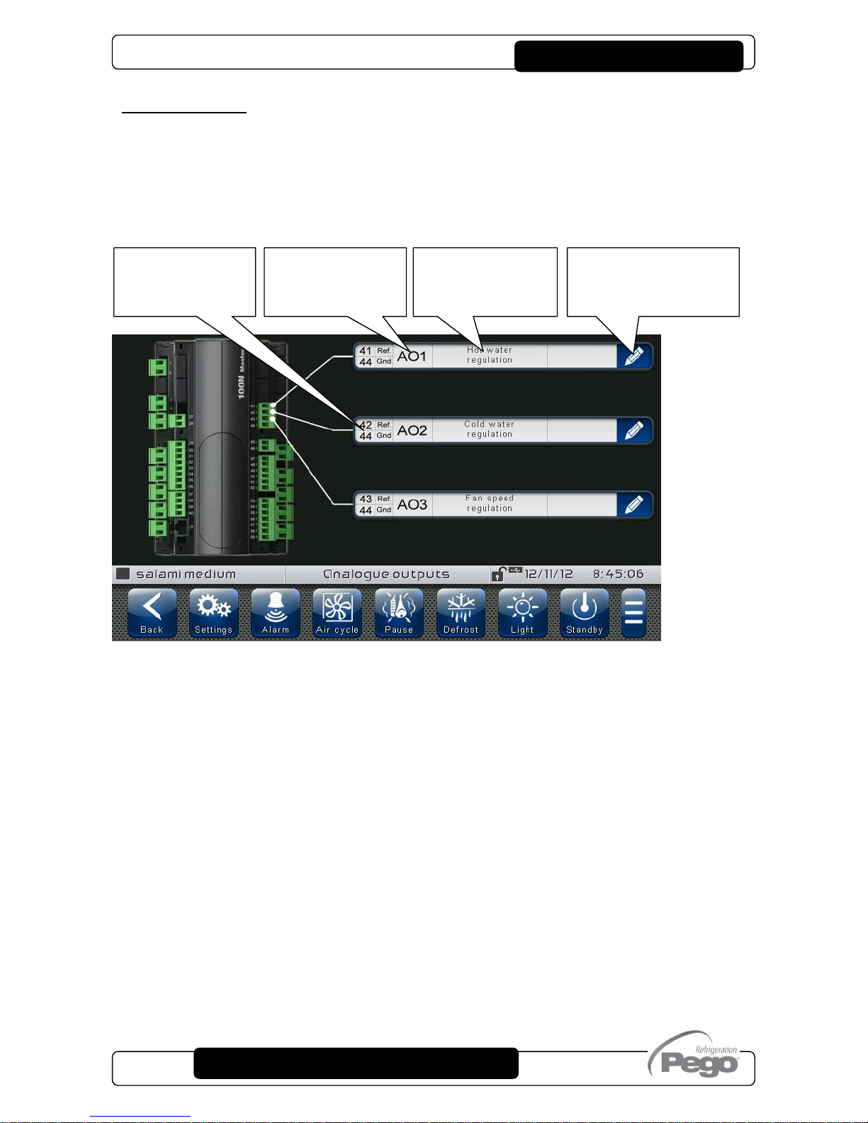
VISION TOUCH PAN
Pag. 79
USER AND MAINTENANCE MANUAL
Rev. 01-19
- Analogue outputs
“Analogue outputs” allows to change the function associated to each analogue output of
the connected 100N MASTER3. The modification of an output puts the control unit in
“Stand by”. In the event a function is not associated to at least one output, the eventual call
from the control unit will not activate any analogue output (only the status icon will be
activated to indicate a call).
Modification of the
function associated
to the analogue
Connection
terminals
Analogue
output
identification
Associated
function
description

VISION TOUCH PAN
Pag. 80
USER AND MAINTENANCE MANUAL
Rev. 01-19
- Analogue inputs
“Analogue inputs” allows to modify the function associated to each analogue input of the
connected 100N MASTER3. The modification of an input puts the control unit in “Stand
by”. In the event of an incorrect association between a probe and a function, the alarm is
signalled (Ec1 ÷ Ec9).
Modification of the
function associated to
the analogue input
Associated
function
description
Analogue
input
identification
Connection
terminals

VISION TOUCH PAN
Pag. 81
USER AND MAINTENANCE MANUAL
Rev. 01-19
I/O status
“I/O Status” allows the status of each input/output of the connected 100N MASTER3 to be
displayed.
The “I/O Status” menu can be accessed from the main Configuration page (“Parameters”
Button). The display of this item can be set in the “Password” sub-menu => “Configure
user level menu” and by selecting the “I/O Status” item (installer login required).
DIGITAL OUTPUTS
DIGITAL INPUTS
ANALOGUE OUTPUTS
ANALOGUE INPUTS
I/O status
Digital outputs status
Digital inputs status
Analogue outputs status
Analogue inputs status

VISION TOUCH PAN
Pag. 82
USER AND MAINTENANCE MANUAL
Rev. 01-19
Program management
PROGRAM MANAGEMENT MANAGER BUTTON:
(Present in the Extended Button bar)
Once this is pressed, the program management screen appears, which allows data to be
imported from or exported to a USB or SD card.
The “Program management” menu allows programs saved on the device to be
imported/exported. This menu can be accessed via the "Manager" button on the Extended
button bar. The display of this item can be set in the “Password” sub-menu => “Configure
user functions” and by selecting the “Recipe Manager” item (installer login required).
Manager
CHAPTER 9: PROGRAM MANAGEMENT
It imports programs from a USB external
memory unit loading them in the internal
memory of the controller
Inside the menu:
= Import from USB
N.B. Make sure that the USB memory unit is inserted
It imports programs from an SD external
memory unit loading them in the internal
memory of the controller
Inside the menu:
= Import from SD
N.B. Make sure that the SD memory unit is inserted
Export programs from internal memory of
the controller to the external USB memory
unit
Inside the menu:
= Export to USB
N.B. Make sure that the USB memory unit is inserted
It exports programs from internal memory
of the controller to the external SD
memory unit
Inside the menu:
= Export to SD
N.B. Make sure that the SD memory unit is inserted

VISION TOUCH PAN
Pag. 83
USER AND MAINTENANCE MANUAL
Rev. 01-19
DIAGNOSTICS
If any faults occur, the 200VTOUCHPAN controller informs the operator, by means of alarm
codes visualised on the display (via pop-up or on the ‘Alarms’ page) and an acoustic signal emitted
by a buzzer inside the operating Console (if enabled). One of the following messages appears on
the screen when an alarm condition occurs:
ALARM
CODE
POSSIBLE CAUSE
SOLUTION
E0
EEPROM Vision Touch alarm
Switch the appliance off and back on.
Select 'Repair EEPROM’ in the
'Software' menu.
If the problem persists, contact the
technical assistance service.
E0m
EEPROM 100N MASTER alarm
Switch the appliance off and back on.
If the problem persists, contact the
technical assistance service.
E1
Probe connected to channel 1 functional fault
Check the probe status.
Verify that its configuration is correct in
the "Configure I/O>Analogue Inputs"
menu.
E2
Probe connected to channel 2 functional fault
Check the probe status.
Verify that its configuration is correct in
the "Configure I/O>Analogue Inputs"
menu.
E3
Probe connected to channel 3 functional fault
Check the probe status.
Verify that its configuration is correct in
the "Configure I/O>Analogue Inputs"
menu.
E4
Probe connected to channel 4 functional fault
Check the probe status.
Verify that its configuration is correct in
the "Configure I/O>Analogue Inputs"
menu.
E5
Probe connected to channel 5 functional fault
Check the probe status.
Verify that its configuration is correct in
the "Configure I/O>Analogue Inputs"
menu.
Eg
General alarm (e.g. Thermal protection or max
pressure switch)
(The outputs are all disabled apart from the alarm
output, if present)
Check compressor absorption.
If the problem persists, contact the
technical assistance service.
Ec
Compressor protection alarm
(The compressor output is disabled)
Check compressor absorption.
If the problem persists, contact the
technical assistance service.
EU
Humidifier alarm
(The humidifier output is disabled)
Check the humidifier status.
If the problem persists, contact the
technical assistance service.
EF
Fans protection
(The fans output is disabled)
Check the fans status.
If the problem persists, contact the
technical assistance service.
CHAPTER 10: DIAGNOSTICS

VISION TOUCH PAN
Pag. 84
USER AND MAINTENANCE MANUAL
Rev. 01-19
En
No connection between Console and MASTER
board.
Check the connection between the two
units.
If the problem persists, contact the
technical assistance service.
EnI
MASTER board initialisation error.
Check the connection between the two
units.
Switch the Vision Touch off and on
again.
If the problem persists, contact the
technical assistance service.
Ed
Dehumidification timeout
The dehumidification output has remained active for a
longer time than the variable dEt.
Check the dehumidifier status.
Increase the set time limit in the
parameter dEt (‘Machine protection'
menu).
Ec1
Configuration Error
Room Temperature probe
Check the configuration of the analogue
inputs
Ec2
Configuration Error
Evaporator Temperature probe
Check the configuration of the analogue
inputs
Check enabling of the evaporator probe
Ec3
Configuration Error
Room Humidity probe
Check the configuration of the analogue
inputs
Check enabling of humidity
management
Ep
Recipe programming error (incorrect time of the
prepared product)
Change the time of the prepared
product
Ag1
General alarm 1 from digital input
Verify the digital input configured as
'Generic warning 1'
Ag2
General alarm 2 from digital input
Verify the digital input configured as
'Generic warning 2'
Ag3
General alarm 3 from digital input
Verify the digital input configured as
'Generic warning 3'
Edi
Digital input configuration error during an import or
update configuration.
Check the configuration of the digital
input
Reconfigure the input disabled
Edo
Digital output configuration error during an import
or update configuration.
Check the configuration of the digital
output
Reconfigure the output disabled
Eai
Analogue input configuration error during an
import or update configuration.
Check the configuration of the analogue
input
Reconfigure the input disabled
Eao
Analogue output configuration error during an
import or update configuration.
Check the configuration of the analogue
output
Reconfigure the output disabled
EPH
High pressure general alarm
(The compressor output is disabled)
Check the refrigerant circuit
If the problem persists, contact the
technical assistance service
EPL
Low pressure general alarm
(The compressor output is disabled)
Check the refrigerant circuit
If the problem persists, contact the
technical assistance service

VISION TOUCH PAN
Pag. 85
USER AND MAINTENANCE MANUAL
Rev. 01-19
Alarms management
By pressing the “Alarms” button one accesses the relative management page that contains
the log relating to the last 30 alarms detected. The alarms can take on different colours:
- RED ALARM: indicates an alarm in progress, not solved.
- ORANGE ALARM: when a red alarm is cleared because the cause is solved, it turns
orange and becomes an alarm to be acquired. If all alarms are cleared the “Alarm” button
turns orange.
- SOLVED ALARM: the acquired alarm is no longer coloured and it stays stored in alarms
management.
RED
ALARM
Solve the
cause
ORANGE
ALARM
Alarm cleared.
Press the alarm
to acquire it
ALARM
SOLVED
Alarm cleared
and acquired
by the user
E-MAIL
SENT
If emails are
enabled, it
indicates the
attempt to
send an email
related to the
alarm
Alarm code
(see Diagnostics)
Alarm description
Date and time
the alarm situation started
Alarm situation
duration
Alarm status
(in progress | cleared | solved)
Alarms list deletion
(button present only if all alarms have been solved)

VISION TOUCH PAN
Pag. 86
USER AND MAINTENANCE MANUAL
Rev. 01-19
Pop-up management
Pop-ups are elements that appear on the screen in order to call the user's attention to
particular situations that may occur during the normal use of the VISION TOUCH PAN
control unit.
RED POP-UP
It may indicate:
- activated alarm warning
- the action that one is about to perform is critical
and irreversible. Pay particular care when
confirming the operation.
YELLOW POP-UP
The operation one is about to perform is critical.
A confirmation is required.
GREEN POP-UP
Device warnings.
It may indicate the completion of a program in
progress
BLUE POP-UP
Device start-up
(date and time are stored in alarms
management)

VISION TOUCH PAN
Pag. 87
USER AND MAINTENANCE MANUAL
Rev. 01-19
INSTALLATION
The Web configuration of the Vision Touch PAN depends on the type of connection.
- Direct connection to the PC
The network card of the computer must be configured in order to have the assignment of
the DHCP address activated. In this case, the Vision Touch PAN and the computer, finding
no DHCP server, will take the default IP addresses previewed for the class of addressing
169.254.xxx.xxx. In order to connect to the device, it will be necessary to open up a
browser page and digit in the address bar the following order:
http://hostname/ where hostname = unique
identifier linked to the serial number present in
the info page (Take look at “Info Page”, chap.
8.3.9).
or
http://169.254.254.1/ (IP default address of the Vision Touch)
CHAPTER 11: WEB SERVER

VISION TOUCH PAN
Pag. 88
USER AND MAINTENANCE MANUAL
Rev. 01-19
- LAN Connection
If connected to a LAN where a DHCP server is present (and the DHCP solicitude is
enabled on the Vision Touch, look at chap. 8.3.9), the Vision Touch will acquire a free IP
address. In this case it is possible to consult the IP address acquired through the “Info
Page” that you find in the “Web server” menu of the Vision Touch.
If the DHCP is not present, Vision Touch maintains the IP address set in the configuration
of the parameters.
Pay attention: in this case, IP conflicts with other devices connected to the LAN could be
possible.
In order to connect to the Vision Touch, i twill be necessary to connect your own device to
the same net, in DHCP mode, or with compatible static IP, open up a browser and digit in
the address bar the following order:
http://hostname/ where hostname = unique
identifier linked to the serial number present in the
info page (look at “Info Page”, chap. 8.3.9).
or
http://XXX.XXX.XXX.XXX/ (Vision Touch IP address, look at “Info Page”, chap. 8.3.9)
NOTE: The Host name of the Vision Touch is a unique reference linked to the serial
number. So that it is possible to connect different Vision Touch devices using the same
LAN net, setting distinct IP addresses in case that a DHCP server is not available.
For if you desire to join the Vision Touch from the web browser, it is sufficient to write in
the address bar:
http://vt_xxxxxxxxxx/
Where xxxxxxxxxx = serial number of the device

VISION TOUCH PAN
Pag. 89
USER AND MAINTENANCE MANUAL
Rev. 01-19
WEB INTERFACE: USER ACCESS
The access to the Web page of the Vision Touch is subject to the access control through
Username and Password.
It is possible to access to the Web pages of the Vision Touch in other two modes:
- basic user: inserting in the “Username” field the user Name set in the “Web server” menu
of the Vision Touch (page “Username”), you log in with the same permits that the basic
user has on the Vision Touch. The installer, inhibiting the functions or the access to the
parameters to the local user, also blocks the access to such features to the basic user who
logs in through the Web page.
- admin user: inserting in the “Username” field the user Name set in the “Web server”
menu of the Vision Touch (page “Username”), and in the “Password” field, the installer
password of the Vision Touch (the one used in the Password menu in order to access as
installer) you log in with the same permits that the installer has on the Vision Touch. So, it
is possible to edit the parameters and access to all the functions (if the Wce parameter
supports the remote command, look at chap. 8.3.9).
Installer login (admin)
User login (basic user)

VISION TOUCH PAN
Pag. 90
USER AND MAINTENANCE MANUAL
Rev. 01-19
WEB INTERFACE: PAGES
The web interface counts with some fixed sections:
On the left: browsing menu of the pages.
At the top: name of the page, serial number and kind of connected user.
On the right: content of the page.
- Homepage
Warning signal
- red: red flag alarm
- grey: no alarm
Loaded program
stopped program
running program
Buttons
- green background: active function
- blue background: inactive function
- grey background: inactive and
inactivable function (basic user)
Current temperature
(and temperature set point)
Current humidity
(and humidity set point)
Browsing menu
of the pages
Kind of access
(admin or basic user)
Current page
Logout
Logs the user out
and brings him back
to the login page

VISION TOUCH PAN
Pag. 91
USER AND MAINTENANCE MANUAL
Rev. 01-19
- PEGO Humidifier
The “Humidifier PEGO” page is visible only if the humidifier is enabled (EUm=1).
The “Stand-by” and “Discharge” buttons are disabled if web commands are disabled
(Wce=0 in Webserver menù) or if the user is not enabled.
Forcing manual
discharge humidifier
Humidifier
(steam present with active
steam production)
Humidifier’s
outputs
Humidifier’s digital
inputs
Stand-by Humififier

VISION TOUCH PAN
Pag. 92
USER AND MAINTENANCE MANUAL
Rev. 01-19
- I/O (Inputs / Outputs)
Input / Output Clamp
PIN on the 100N
MASTER
Input / Output
description (digital or
analogical)
Input / Output status
If digital:
- green: active input / output
- grey: inactive input / output
If analogical:
You visualize the analogical input /

VISION TOUCH PAN
Pag. 93
USER AND MAINTENANCE MANUAL
Rev. 01-19
- Alarms
In the “Alarms” page are visualized all the red falg alarms and those which have
intervened, such as they are memorized in the Alarms page of the Vision Touch (look at
chap. 10.2, Alarm Gesture).
The background color is indicative for the type of alarm:
- Red background: red flag alarm (the starting instant is indicated).
- Yellow background: annulled alarm (the starting instant and the duration are indicated).
- White background: alarm annulled and acquired on the Vision Touch.
NOTE: one cannot proceed to the acquisition of the alarms using the Web page.
Alarm code
Description and
duration of the alarm

VISION TOUCH PAN
Pag. 94
USER AND MAINTENANCE MANUAL
Rev. 01-19
- Controls => Program
In the "Program" page, it is possible to select, start and stop the execution of the programs
saved in the memory of the Vision Touch. The "Play" and "Stop" buttons can be disabled
with Wce parameter.
When manual mode is active, the "Program" page shows the programs list.
By pressing the "Play" button, if the user is enabled (or is an administrator), the product
ready setting page is showed. Pressing "Play", the program is started (after the
consistency check of the planned schedule).
Program name
Settings for product
ready time (changeble)
Start program
Increase / decrease
product ready time
Product ready day selection
(12h/24h/48h/72h)
Play the program

VISION TOUCH PAN
Pag. 95
USER AND MAINTENANCE MANUAL
Rev. 01-19
If the scheduled ready product time is not compatible with the program length, the recipe
programming error is activated.
When a program is running, the following page is showed:
Note: it is possible to deactivate the phase display by clicking on the phases name in the
legend.
Info about product ready time
and current time
Program name
Stop the program
Current temperature
(black triangle)
Steps performed or in progress
(full color)
Next steps
(Transparent)

VISION TOUCH PAN
Pag. 96
USER AND MAINTENANCE MANUAL
Rev. 01-19
- Controls => Parameters
Parameters menu
Click on the indicator in order to
visualize the list of the
parameters.
Parameters menu hidden to the basic user (configuration in
the Password menu on the Vision Touch)
Note: the admin user always has access to the complete list of
the menu.
Current temperature
Current humidity
Phases list
Temperature / humidity setpoint
Phase deadline

VISION TOUCH PAN
Pag. 97
USER AND MAINTENANCE MANUAL
Rev. 01-19
- Info
Parameter code
Parameter description
Current value
Increase or decrease
the value

VISION TOUCH PAN
Pag. 98
USER AND MAINTENANCE MANUAL
Rev. 01-19
COLD/HOT: PRESERVATION OF AMBIENT TEMPERATURE
The cold and hot call is managed in neutral area depending on the set temperature
setpoint (“Set Temp” label in “Home 1”) and to the temperature differentials (parameters
dtC and dtF in “Parameters > Process regulation”). The cold is activated upon exceeding
of set + dtF and remains active until set is achieved (with dnF=0). The hot is activated
below set - dtC and remains active until set is achieved (with dnC=0). It is possible to set a
"dead area" with parameters dtn that deactivates hot and cold when the temperature is
between SET-dnC and SET+dnF.
Parameter C1 (in “Parameters > Machine protection introduces a delay between a switchoff and the subsequent re-activation of the cold. Hot can be deactivated with parameter
EnH in “Parameters > Configure PAN” (EnH=0 disables the hot relay in all conditions).
Cold can be deactivated with parameter EnC in “Parameters > Configure PAN” (EnC=0
disables the cold relay in all conditions).
CHAPTER 12: OPERATION
°C
COLD CALL
HOT CALL
On Cold
Off Cold
Dead area
Off Hot
On Hot
(Set Temp)+dtF
(Set Temp)+dnF
(Set Temp)-dnC
(Set Temp)-dtC
(Set Temp)

VISION TOUCH PAN
Pag. 99
USER AND MAINTENANCE MANUAL
Rev. 01-19
HUMIDIFICATION/DEHUMIDIFICATION: PRESERVATION OF AMBIENT HUMIDITY
The humidity and the dehumidification call is managed in neutral area depending on the
set humidity setpoint (“Set RH%” label in “Home 1”) and to the humidity differentials
(parameters dUU and dUd in “Parameters > Process regulation”). Dehumidification is
activated upon exceeding of set + dUd and remains active until set is achieved (with
dnd=0). Humidification is activated below set - dUU and remains active until set is
achieved (with dnU=0).
It is possible to set a "dead area" with parameters dnd and dnU that deactivates
humidification and dehumidification when humidity is between SET-dnU and SET+dnd.
The humidity management can be excluded with parameter Hr in “Parameters > Configure
PAN”. Dehumidification only can be excluded with parameter End.
Humidification only can be excluded with parameter EnU.
There are four dehumidification methods (parameter dEU in “Parameters > Configure
PAN”):
0. Dehumidifies with the cold (the cold is called to dehumidify, the hot is added only to
maintain ambient temperature)
1. Dehumidifies with the hot (the hot is called to dehumidify, the cold is added only to
maintain ambient temperature)
2. Separate dehumidification (only the dehumidification output activates but hot and cold
are not called)
3. Dehumidification separate and working with cold off (separate dehumidification that
is activated only if a cold call is not in progress)
It is possible to give a maximum time for the dehumidification phase (parameter dEt in
“Parameters > Machine protection”) by signalling an alarm.
DEHUMIDIFY
CALL
HUMIDIFY
CALL
On Dehumidify
Off Dehumidify
Dead area
Off Humidify
On Humidify
(Set RH%)+dUd
(Set RH%)+dnd
(Set RH%)-dnU
(Set RH%)-dUU
(Set RH%)

VISION TOUCH PAN
Pag. 100
USER AND MAINTENANCE MANUAL
Rev. 01-19
0-10V PROPORTIONAL HUMIDIFIER MANAGEMENT
Configure an analogue output (AO1, AO2 or AO3) as "Humidifier control" to activate the
proportional 0-10V management of the humidifier. In this case the analogue output 0-10V
varies proportionally to the ambient humidity as shown in the following graph, where:
Setpoint = Ambient humidity Set – dnU parameter
Differ. = dUU parameter
HmV = minimum value of 0-10V humidifier output
NEW SOFTWARE FEATURES
Rel. 2.0.5.1
- Screensaver function.
Rel. 2.0.10.1
- Added two digital input's configurations for high and low pressure.
- New high and low pressure alarms (EPH, EPL).
-
Rel. 2.0.0.2
- Added Web server.
- Added parameters F3h e F3c for fan management in hot/cold manual mode.
- Added parameter Fdo for fan off delay after deactivating the hot output.
- Added the possibility to modify the temperature / humidity setpoints of the recipe in
progress, if the user is enabled.
Rel. 2.0.1.2
- Humidifier regulation with 0-10V output and HmV parameter added.
- Added automatic time synchronization via the Web.
Rel. 2.0.0.3
- Automatic sending of e-mail in case of alarm.
 Loading...