

Page 1
Cisco Systems, Inc.
1
2
283688
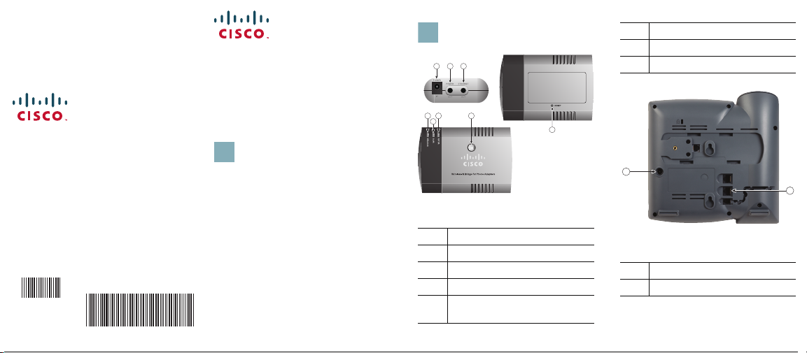
1 2 3
4
5678
www.cisco.com
Small Business Support
www.cisco.com/go/sbsc
Cisco and the Cisco Logo are trademarks of Cisco
Systems, Inc. and/or its affiliates in the U.S. and other
countries. A listing of Cisco's trademarks can be found at
www.cisco.com/go/trademarks. Third party
trademarks mentioned are the property of their
respective owners. The use of the word partner does not
imply a partnership relationship between Cisco and any
other company. (1005R)
Copyright © 2011 Cisco Systems, Inc. All rights
reserved.
Printed in China PRC
78-20173-01
78-20173-01
Quick Start Guide
Configuring the Wireless-N
Bridge for Phone Adapters
6WLAN LED
7WPS LED
8System LED
Cisco Small Business
WBPN Wireless-N Bridge for
Phone Adapters
Before You Begin
Before you begin the installation,
make sure that you have the
following equipment and
information:
• Power Supply for your Small
Business IP Phone (not included)
• PC to use the web-based
system management tools to
configure the WBPN (required if
you are not using Wi-Fi
Protected Setup)
WBPN Connections
1 Power adapter port
2WBPN power cable
3Network cable
4 Reset button
5Wi-Fi Protected Setup
(WPS) button
1
2
283689
Phone Connections
1 Power adapter port
2 Ethernet port
Page 2

Connecting the WBPN
3
If your wireless device supports
Wi-Fi Protected Setup (WPS), you
can connect the WBPN to the
phone and use WPS to connect
the phone your network. If you do
not use WPS, you must connect
the WBPN to a PC and use a web
browser to configure it. See the
User Guide located on Cisco.com
for more information. (For the
location, see the Where to Go
from Here section.)
1 If the IP phone power adapter is
connected to your IP phone,
disconnect it.
2 Unplug the IP phone power
adapter from the power source.
3 Connect the WBPN power
cable to the power port on the
IP phone (labeled #1 in the
“Phone Connections”
graphic).
4 Connect the network cable
from the WBPN to the Ethernet
port on the IP phone (labeled #2
in the “Phone Connections”
graphic).
5 Connect the IP phone power
adapter to the power port on
the WBPN (labeled #1 in the
“WBPN Connections”
graphic).
6 (Optional) Place the WBPN
inside the hollow desktop
phone stand. See the User
Guide for more information.
7 Plug the IP phone power
adapter into the power source.
Using the WPS Push Button
Method
1 After all connections are made
and devices are powered on,
press the WPS button on your
wireless device.
2 Press the WPS button on the
WBPN. The WPS LED on the
WBPN flashes blue during the
discovery period.
3 After the WBPN establishes a
connection to the wireless
device, the WPS LED displays
solid blue, and the WLAN LED
will display either solid green or
flashing green, depending on
network activity.
Using the WPS PIN Method
1 Connect the WBPN and power
on all devices as previously
described.
2 On the bottom of the WBPN
unit, locate the label and make
note of the PIN. The PIN is a
unique numeric code printed on
the label.
3 Connect to your wireless
device’s web interface using a
web browser. Your computer
must be connected to your
wireless network.
4 In your router or device’s WPS
menu, enter the WBPN’s PIN into
the field that allows you to set
up wireless devices using a PIN.
5 Save your changes. The device
should automatically connect to
the WBPN. After the WBPN
establishes a connection to the
wireless device, the WPS LED
displays solid blue, and the
WLAN LED will display either
solid green or flashing green,
depending on network activity.
Where to Go from Here
Cisco Small Business Support
Community:
www.cisco.com/go/ smallbizsuppor t
Phone Support Contacts:
www.cisco.com/support
Product Documentation:
www.cisco.com/go/smallbizphones
Click on the “Voice Gateways and
Accessories” tab.
Cisco Small Business Home:
www.cisco.com/smb
Page 3

Federal Communication
Commission Interference
Statement
This device complies with Part 15 of
the FCC Rules. Operation is subject to
the following two conditions: (1) This
device may not cause harmful
interference, and (2) this device must
accept any interference received,
including int erference that m ay cause
undesired operation.
This equipment has been tested and
found to comply with the limits for a
Class B digital device, pursuant to
Part 15 of the FCC Rules. These
limits are designed to provide
reasonable protection against harmful
interference in a residential installation.
This equipment generates, uses and
can radiate radio frequency energy
and, if not installed and used in
accordance with the instructions, may
cause harmful interference to radio
communications. However, there is
no guarantee that interference will not
occur in a particular installation. If
this equipment does cause harmful
interference to radio or television
reception, which can be determined by
turning the equipment off and on, the
user is encouraged to try to corre ct the
interference by one of the following
measures:
- Reorient or relocate the
receiving antenna.
- Increase the separation between
the equipment and receiver.
- Connect the equipment into an
outlet on a circuit different from
that to which the receiver is
connected.
- Consult the dealer or an
experienced radio/TV technician
for help.
FCC Caution: Any changes or
modifications not expressly approved
by the party responsible for
compliance could void the user's
authority to operate this equipment.
This transmitter must not be
co-located or operating in conjunction
with any other antenna or transmitter.
Radiation Exposure Statement:
This equipment complies with FCC
radiation exposure limits set forth for
an uncontrolled environment. This
equipment should be installed and
operated with minimum distance 20cm
between the radiator & your body.
 Loading...