

Page 1

Mainboard User Guide
IPPSB-DB
Page 2

2
IPPSB-DB Mainboard User Guide
Contents
Contents ....................................................................................2
Introduction ...............................................................................3
Hardware Specications ..........................................................4
Mainboard Layout .....................................................................5
Top view ....................................................................................................... 5
Components ................................................................................................. 6
Selectors ...................................................................................7
Clear CMOS selector (A20/Pitch 2.54mm) ................................................. 7
Intel Management Engine selector (A29/Pitch 2.54mm) .......................... 7
Connectors ................................................................................8
2.5” HDD connector (A1/Pitch 1.27mm) .................................................... 8
ODD Power connector (A2/Pitch 2.0mm) .................................................. 8
SATA HDD Power connector (A3/Pitch 2.0mm) ........................................ 9
SATA connector (A4 and A33/Pitch 1.27mm) ............................................ 9
CPU fan2 connector (A5/Pitch 1.25mm) .................................................. 10
System fan connector (A6/Pitch 1.25mm) ............................................... 10
Panel inverter connector (A7/Pitch 2.0mm) .............................................11
LVDS connector (A9/Pitch 1.0mm) ...........................................................11
Power button/Power LED/Volume control connector
(A10/Pitch 1.0mm) ..................................................................................... 12
EDID connector (A12/Pitch 1.25mm) ....................................................... 12
Webcam+DMIC connector (A13/Pitch 1.0mm) ........................................ 13
Wireless slot (A16/Pitch 0.8mm) .............................................................. 14
LCD mode switch/HD LED/Brightness control connector
(A18/Pitch 1.0mm) ..................................................................................... 15
Card Reader (A19) ..................................................................................... 15
Speaker connector (A23/Pitch 1.25mm) .................................................. 16
RF connector (A24/Pitch 1.5mm) ............................................................. 16
IR connector (A25/Pitch 1.25mm) ............................................................ 17
TV tuner slot (A26/Pitch 0.8mm) .............................................................. 18
Low Pin Count connector (for Debug Card) (A28/Pitch 0.5mm) .......... 19
Page 3

IPPSB-DB Mainboard User Guide 3
“This is the optimally designed mainboard for All-In-One devices which
supports 6 USB ports, VGA Input, Mic input, Audio output, LAN (RJ-45) port,
Memory card reader, 2.5”/3.5” HDD SATA port, ODD SATA port, Webcam,
Speakers, TV tuner, WLAN, RF, IR. The mainboard has a layout specialized
for thermal design and ID structure.”
Introduction
Page 4
4
IPPSB-DB Mainboard User Guide
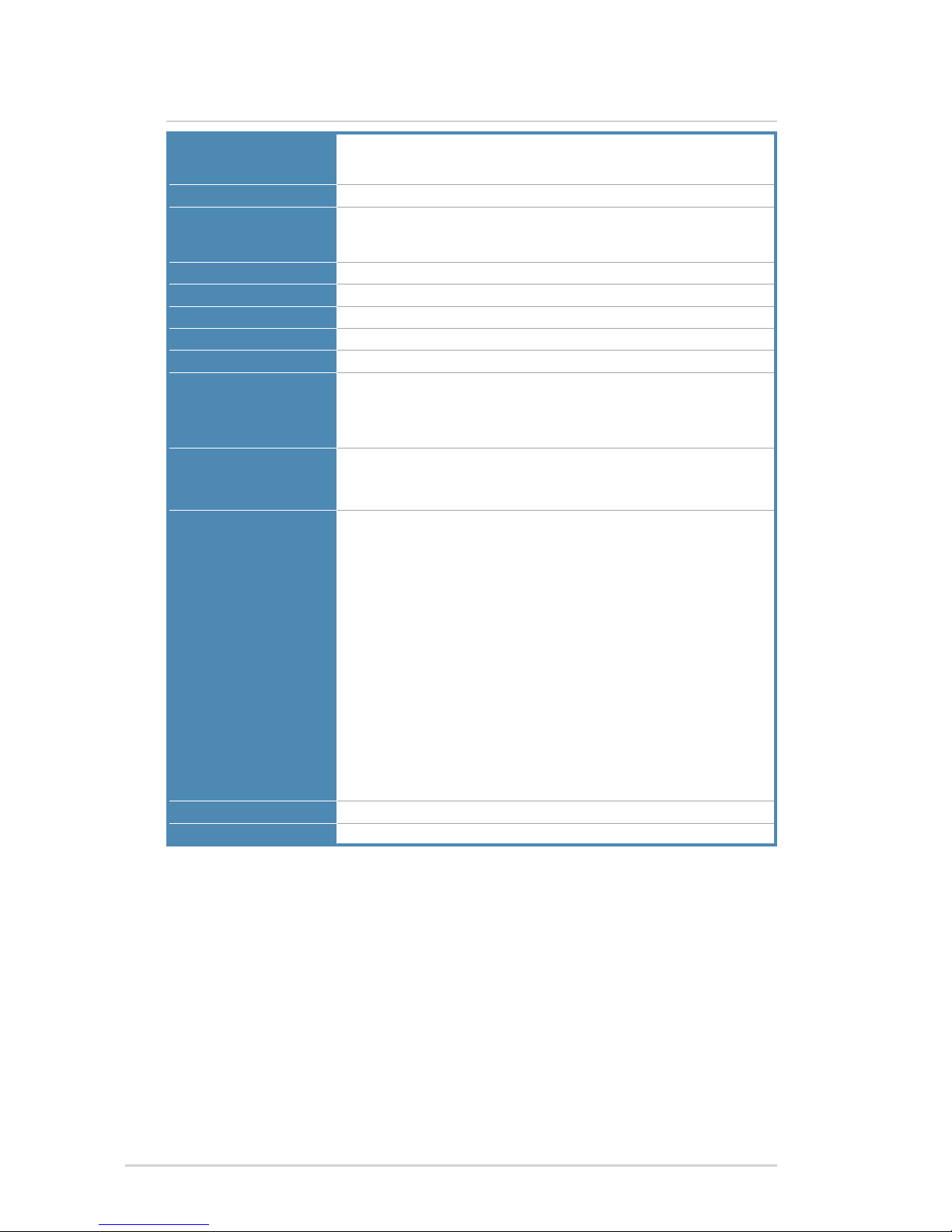
Hardware Specications
CPU
Socket : Intel Socket 1155
Supports : Sandy bridge
TDP : 65W
Chipset
South Bridge : Intel H61
Memory
Dual Channel, 2 slots, Non-ECC, Unbuffered,
204 pin DDR3 SODIMM, Max. 16GB
Types: 1066/PC3-8500, 1333/PC3-10600
Storage
3x SATA ports, SATA300/150
LAN
Gigabit : Realtek RTL8111E-VL
USB
6x USB ports (2x ports convertible to USB 3.0)
Graphics
Integrated Graphics
Audio
Realtek ALC663 (2-channel)
Rear panel I/O ports
1x ATX power port
1x LAN (RJ-45) port
1x Line_out port (convertible to HDMI Out port)
1x Display (VGA In) port
4x USB 2.0 ports
Side panel I/O ports
2x Audio jacks (2-channel)
1x USB 2.0 port (convertible to USB 3.0)
1x USB 2.0 port (convertible to USB 3.0)
1x Card reader port
Internal connectors
1x 2.5” HDD connector (A1/Pitch 1.27mm)
1x ODD Power connector (A2/Pitch 2.0mm) (5V) for slim-ODD or 2.5” HDD
1x SATA HDD Power connector (A3/Pitch 2.0mm) (5V/12V) for 3.5” HDD
2x SATA connectors (A4 and A33/Pitch 1.27mm)
1x CPU fan2 connectors (A5/Pitch 1.25mm) (12V)
1x System fan connector (A6/Pitch 1.25mm) (12V)
1x Panel inverter connector (A7/Pitch 2.0mm)
1x LVDS connector (A9/Pitch 1.0mm)
1x Power button/Power LED/Volume control connector (A10/Pitch 1.0mm)
1x EDID connector (A12/Pitch 1.25mm)
1x Webcam + DMIC connector (A13/Pitch 1.0mm)
1x Wireless slot (A16/Pitch 0.8mm)
1x LCD mode/HD LED/Brightness control connector (A18/Pitch 1.0mm)
1x Card Reader (A19)
1x Speaker connector (A23/Pitch 1.25mm)
1x RF connector (A24/Pitch 1.5mm)
1x IR connector (A25/Pitch 1.25mm)
1x TV tuner slot (A26/Pitch 0.8mm)
1x Low Pin Count connector (for Debug Card) (A28/Pitch 0.5mm)
BIOS
AMI 32Mb (SPI)
Form factor
Proprietary, 7.90 inches x 9.05 inches
Page 5
IPPSB-DB Mainboard User Guide 5
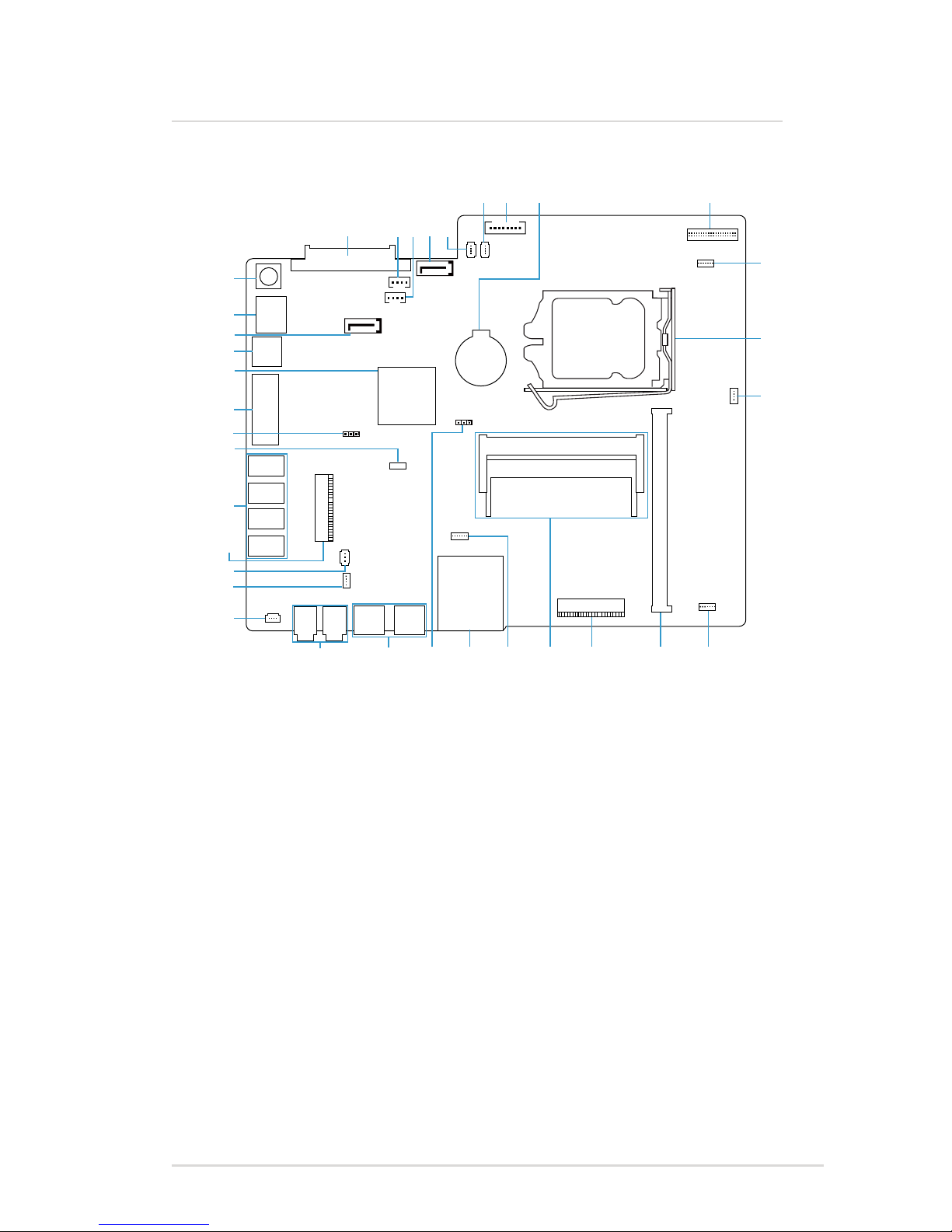
Mainboard Layout
Top view
A1 A2 A3 A4 A5
A7A6 A8 A9
A11
A10
A12
A13A14A16A17
(USB3.0
optional)
A18A19A20A21A22
A24
A23
A25
A26
A27
A28
A29
A30
A32
A31
A33
A34
A35
(HDMI
optional)
Page 6

6
IPPSB-DB Mainboard User Guide
Components
Mainboard Layout
*These components do not have pin denitions shown in this document.
No. Name No. Name No. Name
A1
2.5” HDD
connector
A13
Webcam+DMIC
connector
A26
TV tuner slot
A2
ODD Power
connector
A14*
Mini PCI-E slot
(x16)
A27*
USB 2.0 ports
A3
SATA HDD
Power
connector
A16
Wireless slot
A28
Low Pin Count
connector
(for Debug Card)
A4
SATA connector
A17*
Memory
sockets
A29
Intel
Management
Engine selector
A5
CPU fan2
connector
A18
LCD mode
switch/HD LED/
Brightness
control connector
A30*
VGA In port
A6
System fan
connector
A19
Card reader
A31*
Intel Platform
Controller Hub
A7
Panel inverter
connector
A20
Clear CMOS
selector
A32*
Line_out port
(convertible to
HDMI Out port)
A8*
Battery
A21*
USB 2.0 ports
(convertible to
USB 3.0 ports)
A33
SATA connector
A9
LVDS connector
A22*
Audio jacks
A34*
LAN (RJ-45)
port
A10
Power button/
Power LED/
Volume control
connector
A23
Speaker
connector
A35*
ATX power port
A11*
Intel Socket 1155
CPU Socket
A24
RF connector
A12
EDID
connector
A25
IR connector
Page 7

IPPSB-DB Mainboard User Guide 7
Selectors
Settings:
[2-3] Normal [1-2] Flash override
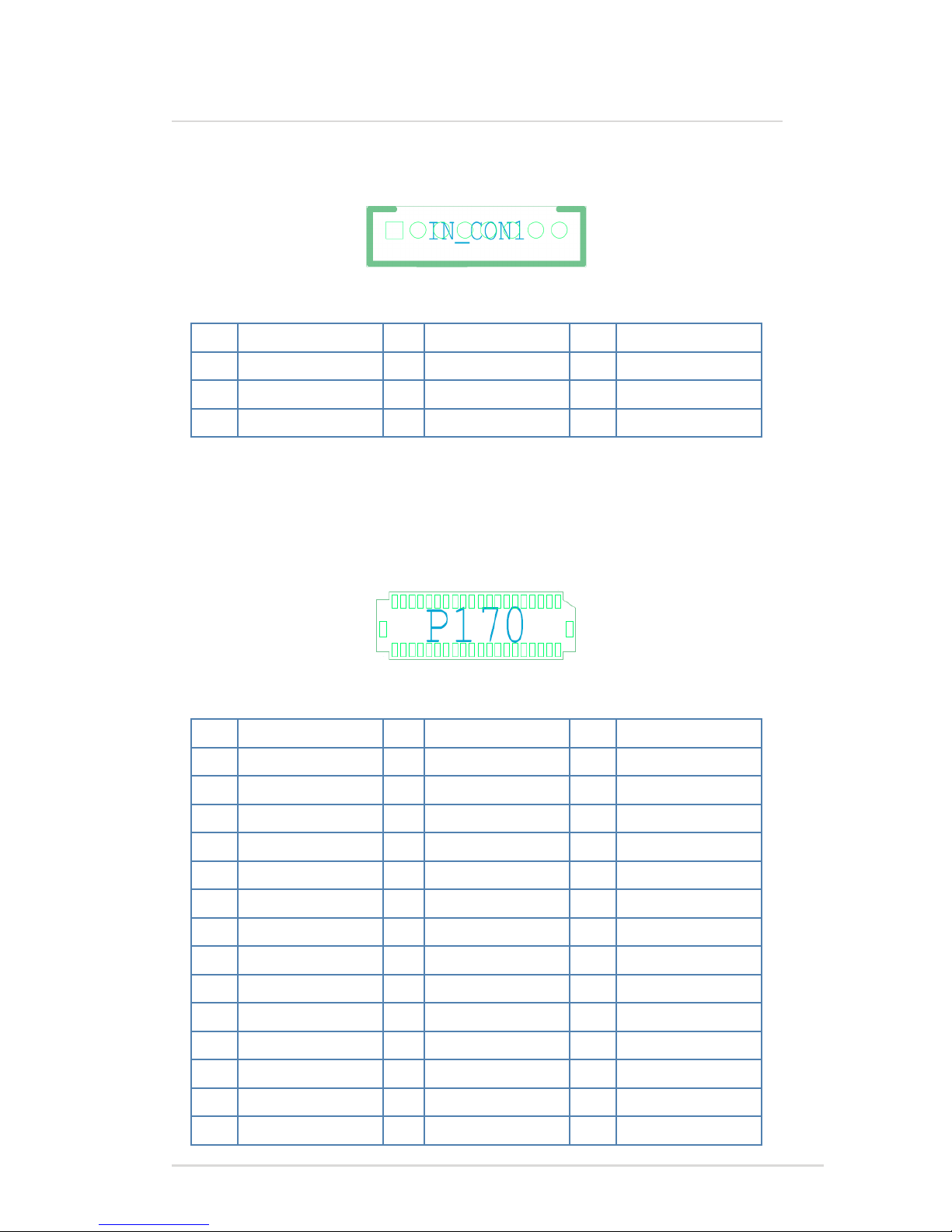
Intel Management Engine selector (A29/Pitch 2.54mm)
Pin Signal Name Pin Signal Name
1 HDA_SDO 3 NC
2 +3P3VSB
Settings:
[1-2] Normal [2-3] Clear CMOS
Clear CMOS selector (A20/Pitch 2.54mm)
Pin Signal Name Pin Signal Name
1 N/C 3 GND
2 RTC_RST#
Page 8

8
IPPSB-DB Mainboard User Guide
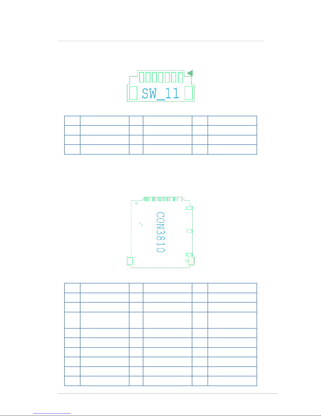
2.5” HDD connector (A1/Pitch 1.27mm)
Pin Signal Name Pin Signal Name Pin Signal Name
1 GND 10 +3P3V 19 GND
2 SATA_TXP0_C 11 GND 20 +12V
3 SATA_TXN0_C 12 GND 21 +12V
4 GND 13 GND 22 +12V
5 SATA_RXN0_C 14 +5V 23
6 SATA_RXP0_C 15 +5V 24
7 GND 16 +5V 25
8 +3P3V 17 GND 26
9 +3P3V 18 GND
ODD Power connector (A2/Pitch 2.0mm)
Connectors
Pin Signal Name Pin Signal Name
1 +5V 3 GND
2 +5V 4 GND
Page 9

IPPSB-DB Mainboard User Guide 9
Connectors
SATA connector (A4 and A33/Pitch 1.27mm)
SATA HDD Power connector (A3/Pitch 2.0mm)
Pin Signal Name Pin Signal Name
1 +5V 3 GND
2 GND 4 +12V
Pin Signal Name Pin Signal Name Pin Signal Name
1 GND 4 GND 7 GND
2 SATA_TXP1 5 SATA_RXN1 8 NC
3 SATA_TXN1 6 SATA_RXP1 9 NC
Page 10

10
IPPSB-DB Mainboard User Guide
Connectors
System fan connector (A6/Pitch 1.25mm)
Pin Signal Name Pin Signal Name
1 GND 3 System_FAN_TACH
2 +12V 4 System_FAN_PWM
Pin Signal Name Pin Signal Name
1 GND 3 CPU_FAN_TACH
2 +12V 4 CPU_FAN_PWM
CPU fan2 connector (A5/Pitch 1.25mm)
Page 11
IPPSB-DB Mainboard User Guide 11
Connectors
Panel inverter connector (A7/Pitch 2.0mm)
LVDS connector (A9/Pitch 1.0mm)
Pin Signal Name Pin Signal Name Pin Signal Name
1 +19VSB 4 GND 7 INV_ADJUST
2 +19VSB 5 GND 8 INV_ENABLE
3 +19VSB 6 GND 9
Pin Signal Name Pin Signal Name Pin Signal Name
1 GND 15 L1_TX2+_NB_C 29 L1_TX0-_NB_C
2 GND 16 L2_TX2+_NB_C 30 L2_TX0-_NB_C
3 L1_TX3+_NB_C 17 L1_TX2-_NB_C 31 GND
4 L2_TX3+_NB_C 18 L2_TX2-_NB_C 32 GND
5 L1_TX3-_NB_C 19 GND 33 NC
6 L2_TX3-_NB_C 20 GND 34 NC
7 GND 21 L1_TX1+_NB_C 35 +5VSB
8 GND 22 L2_TX1+_NB_C 36 +5VSB
9 L1_TXC+_NB_C 23 L1_TX1-_NB_C 37 +5VSB
10 L2_TXC+_NB_C 24 L2_TX1-_NB_C 38 +5VSB
11 L1_TXC-_NB_C 25 GND 39 +5VSB
12 L2_TXC-_NB_C 26 GND 40 +5VSB
13 GND 27 L1_TX0+_NB_C 41 GND
14 GND 28 L2_TX0+_NB_C 42 GND
Page 12

12
IPPSB-DB Mainboard User Guide
Connectors Connectors
Power button/Power LED/Volume control connector (A10/Pitch 1.0mm)
EDID connector (A12/Pitch 1.25mm)
Pin Signal Name Pin Signal Name Pin Signal Name
1 FP_LED+ 4 PWRBTN# 7 GND
2 FP_LED- 5 VOLUME_UP 8 GND
3 +12V 6 VOLUME_DN 9 GND
Pin Signal Name Pin Signal Name
1 DATA 3 GND
2 CLK 4 PWR +5V
Page 13

IPPSB-DB Mainboard User Guide 13
Webcam+DMIC connector (A13/Pitch 1.0mm)
Pin Signal Name Pin Signal Name Pin Signal Name
1 USB PWR +5V 4 GND 7 DMIC_CLK
2 USBP 10-- 5 GND 8 +3P3VSB
3 USBP 10+ 6 DMIC_DATA
Page 14

14
IPPSB-DB Mainboard User Guide
Connectors Connectors
Wireless slot (A16/Pitch 0.8mm)
Pin Signal Name Pin Signal Name Pin Signal Name
1 WAKE# 20 +3.3V 39 +3.3V
2 +3.3V 21 GND 40 GND
3 NC 22 PCIE_RST1# 41 +3.3V
4 GND 23 PE1_RXN0_WLAN 42
5 NC 24 +3.3V 43 GND
6 +1.5V 25 PE1_RXP0_WLAN 44 NC
7 NC 26 GND 45 NC
8 NC 27 GND 46 NC
9 GND 28 +1.5V 47 NC
10 NC 29 GND 48 +1.5V
11 CLK_PCIE_
WLAN#
30 SMB_CLK_S 49 NC
12 NC 31 PE1_TXN0_WLAN 50 GND
13 CLK_PCIE_WLAN 32 SMB_DATA_S 51 NC
14 NC 33 PE1_TXP0_WLAN 52 +3.3V
15 GND 34 GND 53 GND
16 NC 35 GND 54 GND
17 NC 36 HUB_USBN1_BT 55 NC
18 GND 37 GND 56 NC
19 NC 38 HUB_USBP1_BT
Page 15
IPPSB-DB Mainboard User Guide 15
Card Reader (A19)
LCD mode switch/HD LED/Brightness control connector (A18/Pitch
1.0mm)
Pin Signal Name Pin Signal Name Pin Signal Name
1 HDD_LED+ 4 MODE 7 GND
2 HDD_LED- 5 BRIGHT_UP 8 GND
3 +12V 6 BRIGHT_DOWN 9 GND
Pin Signal Name Pin Signal Name Pin Signal Name
1 DATA2 10 DATA2 19 DATA1
2 GND 11 CARD_3V3_CON 20 SD_CD#
3 DATA3 12 DATA0 21 GND
4 +3V 13 DATA1 22 SD_WP
5 MS_CLK 14 SD_CLK 23 GND
6 SD_CMD 15 MS_BS 24 GND
7 DATA3 16 GND 25 NC
8 MS_INS# 17 GND 26 NC
9 GND 18 DATA0
Page 16

16
IPPSB-DB Mainboard User Guide
Connectors Connectors
RF connector (A24/Pitch 1.5mm)
Speaker connector (A23/Pitch 1.25mm)
Pin Signal Name Pin Signal Name
1 +5V_DUAL_USB 3 HUB_USBP4_RF
2 HUB_USBN4_RF 4 GND
Pin Signal Name Pin Signal Name Pin Signal Name
1 SPKR _OUT_R- 3 SPKR_OUT_L- 5 GND
2 SPKR _OUT_R+ 4 SPKR_OUT_L+ 6 GND
Page 17

IPPSB-DB Mainboard User Guide 17
IR connector (A25/Pitch 1.25mm)
Pin Signal Name Pin Signal Name Pin Signal Name
1 RX_NR# 3 +5VSB 5 GND
2 GND 4 GND
Page 18

18
IPPSB-DB Mainboard User Guide
Connectors Connectors
TV tuner slot (A26/Pitch 0.8mm)
Pin Signal Name Pin Signal Name Pin Signal Name
1 WAKE# 20 +3V 39 +3.3VSB
2 +3V 21 GND 40 GND
3 NC 22 PCIE_RST1# 41 +3.3VSB
4 GND 23 PE1_RXN1_TV 42 NC
5 NC 24 +3V 43 GND
6 +1.5V 25 PE1_RXP1_TV 44 NC
7 NC 26 GND 45 NC
8 NC 27 GND 46 NC
9 GND 28 +1.5V 47 NC
10 NC 29 GND 48 +1.5V
11 CLK_PCIE_TV# 30 SMB_CLK_S 49 NC
12 NC 31 PE1_TXN1_TV 50 GND
13 CLK_PCIE_TV 32 SMB_DATA_S 51 NC
14 NC 33 PE1_TXP1_TV 52 +3V
15 GND 34 GND 53 GND
16 NC 35 GND 54 GND
17 NC 36 NC 55 NC
18 GND 37 GND 56 NC
19 NC 38 NC
Page 19

IPPSB-DB Mainboard User Guide 19
Low Pin Count connector (for Debug Card) (A28/Pitch 0.5mm)
Pin Signal Name Pin Signal Name Pin Signal Name
1 +3P3VSB 5 NC 9 GND
2 LAD0 6 LAD2 10 LFRAME#
3 +3P3VSB 7 NC 11 GND
4 LAD1 8 LAD3 12 CK_33M_DEBUG
 Loading...