

Page 1

Dell Rugged Extreme 14-7404
Regulatory Model: P45G
Regulatory Type:P45G001
RFID Model: DWRFID1302
Setup And Features Information
Page 2

Notes, Cautions, and Warnings
NOTE: A NOTE indicates important information that helps you make better use of your computer.
CAUTION: A CAUTION indicates either potential damage to hardware or loss of data and tells you
how to avoid the problem.
WARNING: A WARNING indicates a potential for property damage, personal injury, or death.
© 2013 Dell Inc. All Rights Reserved.
Trademarks used in this text: Dell™, the Dell logo, Dell Boomi™, Dell Precision™ , OptiPlex™, Latitude™, PowerEdge™,
PowerVault™, PowerConnect™, OpenManage™, EqualLogic™, Compellent™, KACE™, FlexAddress™, Force10™, Venue
and Vostro™ are trademarks of Dell Inc. Intel®, Pentium®, Xeon®, Core® and Celeron® are registered trademarks of
Intel Corporation in the U.S. and other countries. AMD® is a registered trademark and AMD Opteron™, AMD Phenom
and AMD Sempron™ are trademarks of Advanced Micro Devices, Inc. Microsoft®, Windows®, Windows Server®,
Internet Explorer®, MS-DOS®, Windows Vista® and Active Directory® are either trademarks or registered trademarks of
Microsoft Corporation in the United States and/or other countries. Red Hat® and Red Hat® Enterprise Linux® are
registered trademarks of Red Hat, Inc. in the United States and/or other countries. Novell® and SUSE® are registered
trademarks of Novell Inc. in the United States and other countries. Oracle® is a registered trademark of Oracle
Corporation and/or its affiliates. Citrix®, Xen®, XenServer® and XenMotion® are either registered trademarks or
trademarks of Citrix Systems, Inc. in the United States and/or other countries. VMware®, vMotion®, vCenter®,
vCenter SRM™ and vSphere® are registered trademarks or trademarks of VMware, Inc. in the United States or other
countries. IBM® is a registered trademark of International Business Machines Corporation.
2014 -01
Rev. A00
™
™
Page 3

Contents
1 Front and Back View.................................................................................................5
2 Quick Setup................................................................................................................ 7
3 Removing and Installing Components................................................................9
Removing the Battery..........................................................................................................................10
Installing the Battery............................................................................................................................10
Removing the Hard Drive.................................................................................................................... 11
Installing the Hard Drive...................................................................................................................... 11
Opening The Press-Latch doors.........................................................................................................12
Closing The Press-Latch doors...........................................................................................................12
Opening The Slide-Latch doors..........................................................................................................12
Closing The Slide-Latch doors............................................................................................................12
4 Smart Cards.............................................................................................................. 13
5 Specifications...........................................................................................................15
6 Information para NOM (únicamente para México)........................................ 21
7 Finding More Information and Resources........................................................23
8 Contacting Dell.......................................................................................................25
Page 4

4
Page 5
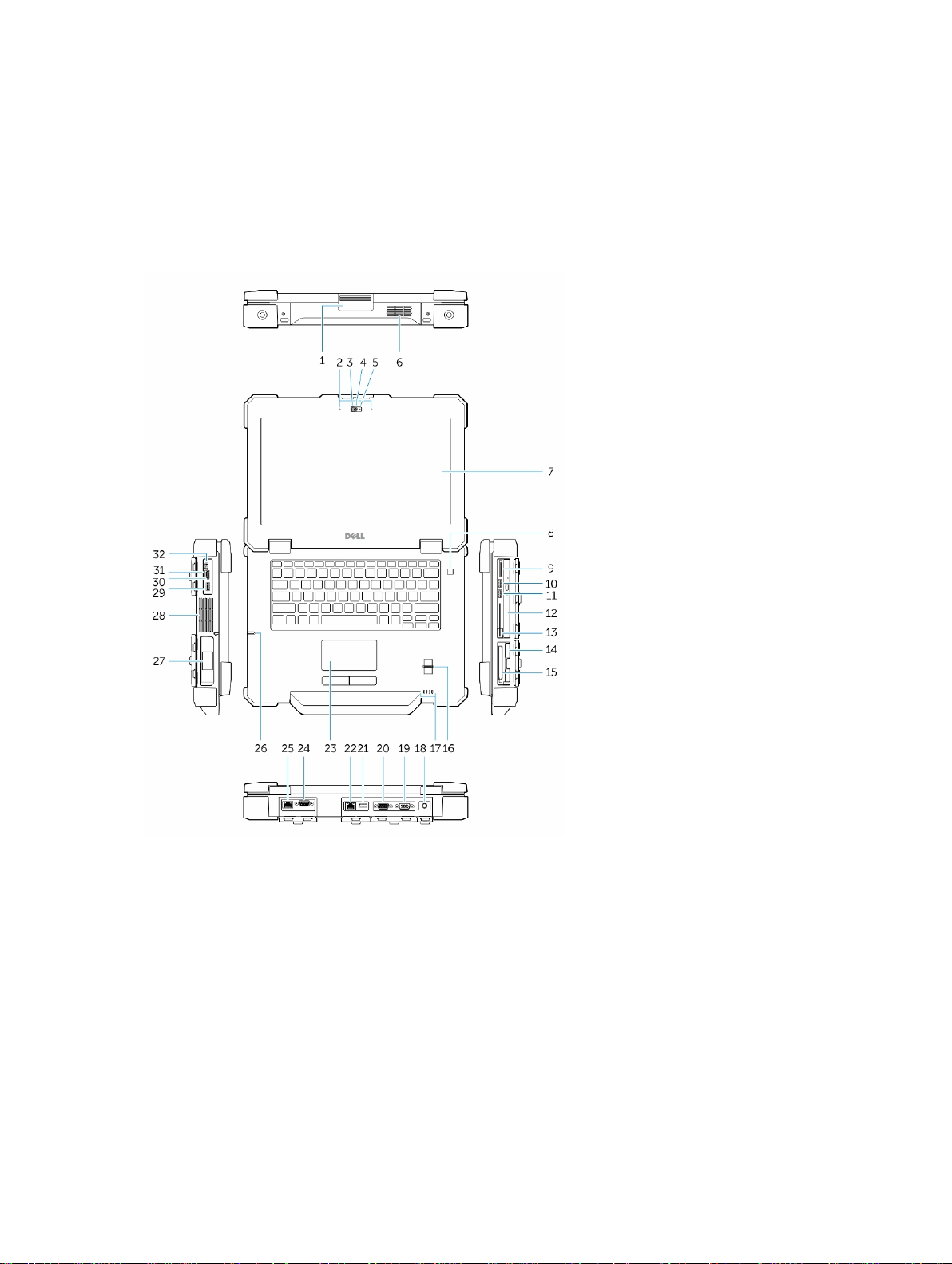
Front and Back View
1
Figure 1. Front view
1. Display latch 2. Microphone
3. Privacy shutter 4. Camera (optional)
5. Camera status light 6. Speaker
7. Outdoor readable display/touchscreen
(optional)
9. Memory-card reader 10. USB 2.0 Connector
11. USB 3.0 Connector 12. Optical drive
13. Secure-card reader 14. Hard disk
15. PC/Express Card Reader 16. Finger Print Reader
17. Status Lights 18. Power Connector
8. Power button
5
Page 6
19. VGA Connector 20. Serial Connector
21. USB 2.0 Connector 22. Network Connector
23. Touch pad 24. Serial Connector
25. Network Connector 26. Stylus
27. Battery 28. Sealed thermal chamber
29. USB 3.0 connector with PowerShare 30. HDMI Connector
31. SIM card connector 32. Audio connector
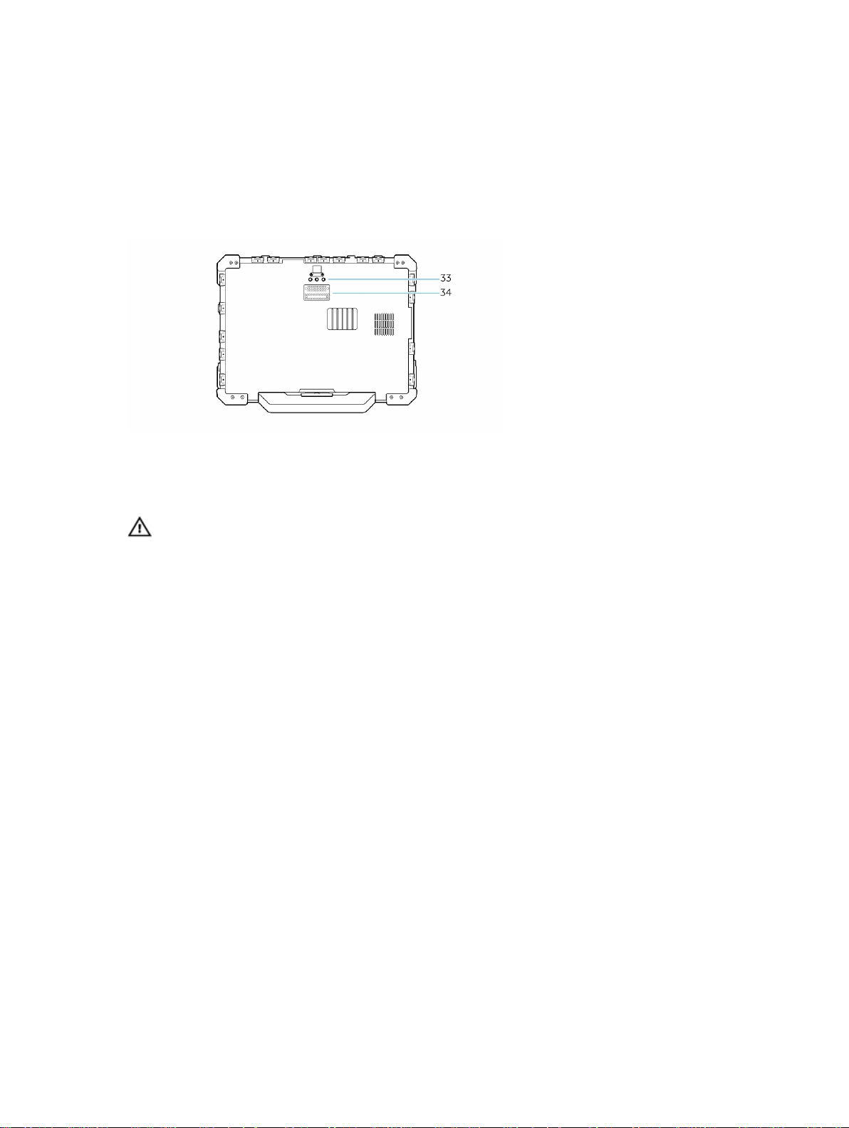
Figure 2. Bottom view
• 33 Radio frequency pass-through connectors
• 34 Docking device connector
WARNING: Do not block, push objects into, or allow dust to accumulate in the air vents. Do not
store your Dell computer in a low-airflow environment, such as a closed briefcase, while it is
running. Restricting the airflow can damage the computer or cause a fire. The computer turns on
the fan when the computer gets hot. Fan noise is normal and does not indicate a problem with
the fan or the computer.
6
Page 7
2
Quick Setup
WARNING: Before you begin any of the procedures in this section, read the safety information
that shipped with your computer. For additional best practices information, see www.dell.com/
regulatory_compliance
WARNING: The AC adapter works with electrical outlets worldwide. However, power connectors
and power strips vary among countries. Using an incompatible cable or improperly connecting
the cable to the power strip or electrical outlet may cause fire or equipment damage.
CAUTION: When you disconnect the AC adapter cable from the computer, grasp the connector,
not the cable itself, and pull firmly but gently to avoid damaging the cable. When you wrap the
AC adapter cable, ensure that you follow the angle of the connector on the AC adapter to avoid
damaging the cable.
NOTE: Some devices may not be included if you did not order them.
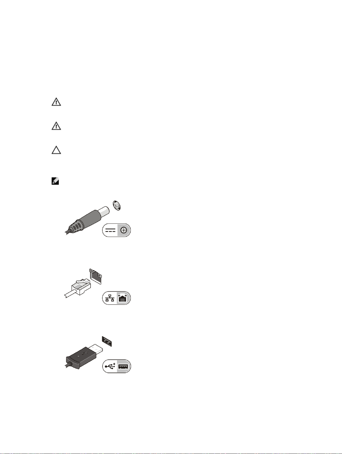
1. Connect the AC adapter to the AC adapter connector on the computer and to the electrical outlet.
Figure 3. AC Adapter
2. Connect the network cable (optional).
Figure 4. Network Connector
3. Connect USB devices, such as a mouse or keyboard (optional).
Figure 5. USB Connector
7
Page 8
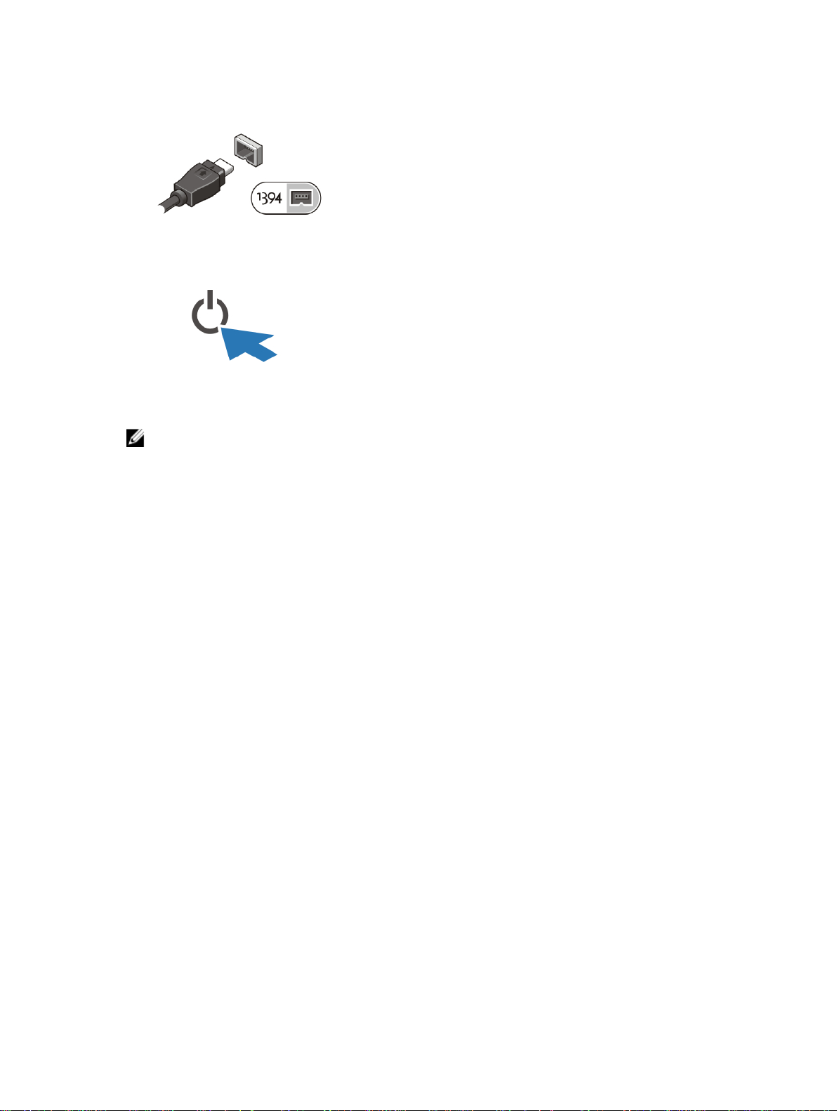
4. Connect IEEE 1394 devices, such as a 1394 hard drive (optional).
Figure 6. 1394 Connector
5. Open the computer display and press the power button to turn on the computer.
Figure 7. Power Button
NOTE: It is recommended that you turn on and shut down your computer at least once before you
install any cards or connect the computer to a docking device or other external device, such as a
printer.
8
Page 9

Removing and Installing Components
This section provides detailed information on how to remove or install the components from your
computer.
3
9
Page 10

Removing the Battery
1. WARNING: Not for use in hazardous locations. See installation instructions.
WARNING: Using an incompatible battery may increase the risk of fire or explosion. Replace
the battery only with a compatible battery purchased from Dell. The battery is designed to
work with your Dell computer. Do not use a battery from other computers with your
computer.
WARNING: Before removing or replacing the battery, turn off the computer, disconnect the
AC adapter from the electrical outlet and the computer, disconnect the modem from the wall
connector and computer, and remove any other external cables from the computer.
WARNING: To prevent ignition in a hazardous atmosphere, batteries must only be changed
or charged in an area known to be non-hazardous.
WARNING: Utilisation d'une batterie non compatible peut accroître le risquevd'incendie ou
d'explosion. Cet ordinateur ne doit utiliser qu'une batterie achetée chez Dell. Nevpas utiliser
les batteries des autres ordinateurs.
WARNING: Avant de retirer la batterie, arrêtez l'ordinateur, et retirez les câbles externes (y
compris l'adaptateur secteur).
WARNING: ll y a danger d’explosion s’il y a remplacement incorrect de la batterie. Remplacer
uniquement ave une batterue due mere type ou d’un type equivalent recommande par le
constructeur. Mettre au rebut les batteries usagees confromement aux instructions du
fabricant.
Perform the following steps to open the battery door latch:
a) Slide the battery latch door to the left and then push it in a downward direction .
b) The door can now be opened by sliding the latch towards the rear of the computer, and rotating
the door in a downward direction.
2. Perform the following steps to remove the battery :
a) Slide the battery release latch to the right to unlock it.
b) Pull the battery outwards and remove it from the computer.
Installing the Battery
1. Slide the battery into its slot until it clicks into place.
2. Rotate the battery door back into its closed position and press until you can hear it click in place.
3. Engage the lock by pushing to the right until the lock symbol is visible.
10
Page 11

Removing the Hard Drive
1. Perform the following steps:
a) To open the hard drive latch door, push the lock button to the right first and then in a downward
direction.
b) Open the hard drive latch door by pushing the latch towards the rear of the computer.
2. Perform the following steps to remove the hard drive :
a) Slide the hard drive release latch to the left.
b) Pull the hard drive outwards and remove it from the computer.
Installing the Hard Drive
1. Push the hard drive into its compartment until its snaps in place.
2. Rotate the door back towards the computer and press until it is in a closed position.
11
Page 12

Opening The Press-Latch doors
There are three press-latch doors. Two on the back and one on the right side panel. Follow the steps
below to open the press-latch doors :
a) Push the slide-lock to the left (the latch is locked when slid to the right).
b) The door can now be opened by pressing down on the latch and pulling the door in a direction
away from the computer.
Closing The Press-Latch doors
Follow the steps below to close the press-latch doors :
a) Rotate the door back towards the computer and press until it is in a closed position.
b) Engage the lock by pushing to the right until the lock symbol is visible.
Opening The Slide-Latch doors
There are three slide-latch doors. Two on the left and one on the right side panel. Follow the steps
below to open the press-latch doors :
a) Push the slide-latch in (the latch is locked when slid outward from the computer).
b) The door can now be opened by sliding the latch towards the rear of the computer, and rotating
the door in a downward direction.
Closing The Slide-Latch doors
Follow the steps below to close the slide-latch doors :
a) Rotate the door back into its closed position and press until you can hear it click in place.
12
Page 13

4
Contactless Smart Cards — These cards do not require any physical contact with the reader. The
chip communicates with the card reader through RFID (DWRFID1302) induction technology.
Smart Cards
There are two main types of Smart or Common Access Cards (CAC):
1. Enclosed Smart Cards — These cards have a contact area with many gold plated connection pads.
When inserted into a card reader, the information from the chip can be read and written
The Smart Card can be fully inserted, allowing the protective hinged door to be closed. Insert the
card into the smart card slot with the gold contact pad facing upward and pointing toward the smart
card slot. Slide the card into the slot until it is fully seated in its connector.
2.
These cards require only close proximity to an antenna of a card reader to complete transactions.
13
Page 14

14
Page 15

Specifications
NOTE: Offerings may vary by region. For more information regarding the configuration of your
computer, click Start (Start icon) → Help and Support, and then select the option to view
information about your computer.
Table 1. System Information
Feature Specification
Chipset Intel Mobile Express Series 6 chipset
DRAM bus width 64-bit
Flash EPROM SPI 32Mbits
PCIe Gen1 bus 100 MHz
Table 2. Processor
Feature Specification
5
Types
L3 cache up to 6 MB
External bus frequency 1333 MHz
Table 3. Memory
Feature Specification
Memory connector two SODIMM slots
Memory capacity 2 GB, 4 GB, or 8 GB
Memory type DDR3 SDRAM 1600 Mhz
Minimum memory 2 GB
Maximum memory 16 GB
Table 4. Audio
Feature Specification
Type four-channel high definition audio
Controller IDT 92HD90
• Intel Core i3 series
• Intel Core i5 series
• Intel Core i7 series
15
Page 16

Feature Specification
Stereo conversion 24-bit (analog-to-digital and digital-to-analog)
Interface:
Internal high definition audio
External microphone-in/stereo headphones/external speakers
connector
Speakers one
Internal speaker amplifier 1W (RMS)
Volume controls Volume Up/Volume Down buttons
CAUTION: Adjustment of volume control, as well as the equalizer in the operating system and/or
equalizer software, to other settings than the center position may increase the earphones and/or
headphones output and cause hearing damage or loss.
Table 5. Video
Feature Specification
Type integrated on system board
Controller Nvidia GeForce (N14M-GE) Discrete Graphics Card, 2 GB
Graphics
Table 6. Communications
Feature Specification
Network adapter 10/100/1000 Mb/s Ethernet (RJ-45)
Wireless
• Internal wireless local area network (WLAN)
Bluetooth
Table 7. Ports and Connectors
Feature Specification
Audio (optional) one microphone/stereo headphone/speakers connector
Video
• one 15-pin VGA connector
• 19-pin HDMI connector
Network adapter one RJ-45 connector
USB 2.0 one 4–pin USB 2.0–compliant connector
USB 3.0 one 4-pin USB 3.0-compliant connector with PowerShare
Memory card reader one 8-in-1 memory card reader
Serial two DB9 pin serial connectors
16
Page 17

Feature Specification
Docking port one
Subscriber Identity Module (SIM) port one
Table 8. Display
Feature Specification
Type white Light Emitting Diode (WLED) display
Size 14.0 inches
Dimensions:
Height 190.00 mm (7.48 inches)
Width 323.5 mm (12.59 inches)
Diagonal 375.2 mm (14.77 inches)
Active area (X/Y) 309.4 mm x 173.95 mm
Maximum resolution
• 1366 x 768 pixels
• 1920 x 1080 pixels
Maximum Brightness 630 nits
Operating angle 0° (closed) to 180°
Refresh rate 60 Hz
Minimum Viewing angles:
Horizontal
• +/- 70° for HD
• +/- 70° for FHD
Vertical
• +10°/-30° for HD
• +/-50° for FHD
Pixel pitch 0.2265 mm
Table 9. Keyboard
Feature Specification
Number of keys United States: 86 keys, United Kingdom: 87 keys, Brazil:
87 keys, and Japan: 90 keys
Layout QWERTY/AZERTY/Kanji
Table 10. Touchpad
Feature Specification
Active Area:
X-axis 91 mm (3.58 inches)
17
Page 18

Feature Specification
Y-axis 51 mm (2.00 inches)
Table 11. Battery
Feature Specification
Type 6–cell or 9–cell “smart” lithium ion
Dimensions:
Height 21 mm (0.82 inches)
Width 166.9 mm (6.57 inches)
Depth 80 mm (3.14 inches)
Weight 6–cell : 365.5 g (0.80 lbs) ; 9–cell : 520 g (1.14 lbs)
Voltage 14.8 VDC
Temperature range:
Operating -29°C to 63°C ( to –20°F to145°F )
Non-Operating –51°C to 71 °C (–60 °F to 160 °F)
NOTE: The battery pack is capable of safely
withstanding the above storage temperatures with
100% charge.
NOTE: The battery pack is also capable of
withstanding storage temperatures from –20 °C to
+60 °C with no degradation in its performance.
Coin-cell battery 3 V CR2032 lithium coin cell
Table 12. AC Adapter
Type 65 W/90 W
Input voltage 100 VAC to 240 VAC
Input current (maximum) 1.7 A/2.5 A
Input frequency 50 Hz to 60 Hz
Output power 65 W/90 W
Output current 3.34 A/4.62 A(continuous)
Rated output voltage 19.5 +/– 1.0 VDC
Temperature range:
Operating 0 °C to 40 °C (32 °F to 104 °F)
Non-Operating –40 °C to 70 °C (–40 °F to 158 °F)
18
Page 19

Table 13. Auto-air Adapter
Type 90 W
Input voltage 11 VDC to 16 VDC
Input current (maximum) 9.0 A
Output power 90 W
Output current 4.86 A(continuous)
Rated output voltage 19.5 +/– 1.0 VDC
Temperature range:
Operating 0 °C to 35 °C (32 °F to 95°F)
Table 14. Physical
Feature Specification
Height 51.5 mm (2.02 inches)
Width 356.1 mm (14.01 inches)
Depth 247.5 mm (9.74 inches)
Weight 8.4 lbs (3.81 kg)
Table 15. Environmental
Feature Specification
Temperature:
Operating –29 °C to 63 °C (32 °F to 95 °F)
Storage –40 °C to 65 °C (–40 °F to 149 °F)
Relative humidity (maximum):
Operating 10 % to 90 % (non condensing)
Storage 5 % to 95 % (non condensing)
Altitude (maximum):
Operating –15.24 m to 3048 (–50 ft to 10,000 ft ft)
Non-Operating –15.24 m to 10,668 m (–50 ft to 35,000 ft)
Airborne contaminant level G1 as defined by ISA-71.04–1985
19
Page 20

20
Page 21

6
Information para NOM (únicamente para
México)
The following information is provided on the device described in this document in compliance with the
requirements of the official Mexican standards (NOM).
Voltaje de alimentación
Frecuencia 50 Hz – 60 Hz
Consumo eléctrico 1,7 A/2,5 A
Voltaje de salida 19,50 V de CC
Intensidad de salida 3,34 A/4,62 A
100 VAC – 240 VAC
21
Page 22

22
Page 23

Finding More Information and Resources
See the safety and regulatory documents that shipped with your computer and the regulatory
compliance website at www.dell.com/regulatory_compliance for more information on:
• Safety best practices
• Regulatory certification
• Ergonomics
See www.dell.com for additional information on:
• Warranty
• Terms and Conditions (U.S. only)
• End User License Agreement
Additional information on your product is available at www.dell.com/support/manuals
7
23
Page 24

24
Page 25

8
Contacting Dell
NOTE: If you do not have an active Internet connection, you can find contact information on your
purchase invoice, packing slip, bill, or Dell product catalog.
Dell provides several online and telephone-based support and service options. Availability varies by
country and product, and some services may not be available in your area. To contact Dell for sales,
technical support, or customer service issues:
1. Visit dell.com/support
2. Select your support category.
3. Verify your country or region in the Choose a Country/Region drop-down menu at the top of page.
4. Select the appropriate service or support link based on your need.
25
 Loading...