

Page 1

OL-30545-01
Cisco Model DPC3829 and
DPC3829M DO CSI S 3.0 8x4
Wireless Residential Gateway
User Guide
Page 2

Please R ead
Important
Please read this entire guide. If this guide provides installation or operation
instructions, give particular attention to all safety statements included in this guide.
Page 3

Notices
T rademark Acknowledgm ents
Cisco and the Cisco logo are trademarks or registered trademarks of Cisco and/or its
affiliates in the U.S. and other countries. To view a list of Cisco trademarks, go to this
URL: www.cisco.com/go/trademarks. DOCSIS is a registered trademark of Cable
Television Laboratories, Inc., and PacketCable is a trademark of Cable Television
Laboratories, Inc. The Wi-Fi Protected Setup mark is a mark of the Wi-Fi Alliance.
Wi-Fi Protected Setup is a trademark of the Wi-Fi Alliance.
Other third party trademarks mentioned are the property of their respective owners.
The use of the word partner does not imply a partnership relationship between
Cisco and any other company. (1110R)
Publication Disclaimer
Cisco Systems, Inc. assumes no responsibility for errors or omissions that may
app ea r in this publication. We reserve the right to change this publication at any
time without notice. This document is not to be const rued as conferring by
implication, estoppel, or otherwise any license or right under any copyright or
pat ent , whether or not the use of any information in this document employs an
invention claimed in any existing or later issued patent.
Disclaimer
The maximum performance for wireless is derived from IEEE Standard 802.11
specifications. Actual performance can vary, including lower wireless network
ca pacity, data t hroughput rate, range and coverage. Performance depends on ma ny
factors, conditions and variables, including distance from the access point, volume of
network traffic, building materials and construction, operating system used, mix of
wireless products used, interference and other adverse conditions.
Software and Firmware Use
The software described in this document is protected by copyright law and
furnished to you under a licens e agreement. You may only use or copy this softwa re
in accordance with the terms of your license agreement.
The firmware in this equipment is protected by copyright law. You may only use the
firmware in the equipment in which it is provided. Any reproduction or distribution
of this firmware, or any portion of it, without our express written consent is
prohibited.
Page 4

Copyright
© 2013 Cisco Systems, Inc. All rights reserved. Printed in the United States of
America.
Information in this publication is subject to cha nge without notice. No part of this
publication may be reproduced or transmitted in any form, by photocopy,
microfilm, xerography, or any other means, or incorporated into any information
retrieval system, electronic or mechanical, for any purpose, without the express
permission of Cisco Systems, Inc.
Page 5

OL-30545-01 iii
Contents
IMPORTANT SAFETY INSTRUCTIONS vii
United States FCC Com pl iance xi
Chap ter 1 Introducing the DOCSIS Wireless Residential Gat ew ay 1
Introduction ......................................................................................................................... 2
What's In th e Carto n? .......................................................................................................... 3
Front Panel Description ...................................................................................................... 4
Back Panel Desc ription ....................................................................................................... 6
Chapter 2 Installing the DOCSIS Wireless Residential Gateway 9
Installation P reparations ................................................................................................... 10
Install the Wir el ess Res idential Gateway ........................................................................ 15
Cha pt er 3 Oper ati o n of F ront Pan el Indicators 17
Initial Power Up, Calibration, and Registration (AC Power Appli ed).......................... 18
Normal Op era tio ns (AC Pow er Applied) ....................................................................... 20
Special Co nditio ns ............................................................................................................. 21
Chapter 4 Tr oub leshoo tin g th e DOCS IS Wire les s R esid en t ial
Gateway 23
Fre que nt ly Ask ed Questions ............................................................................................ 24
Common Troubleshooting Issues .................................................................................... 29
Tips for Improv ed Performa nce ....................................................................................... 30
Chapter 5 Customer Infor mation 31
Index 33
Page 6
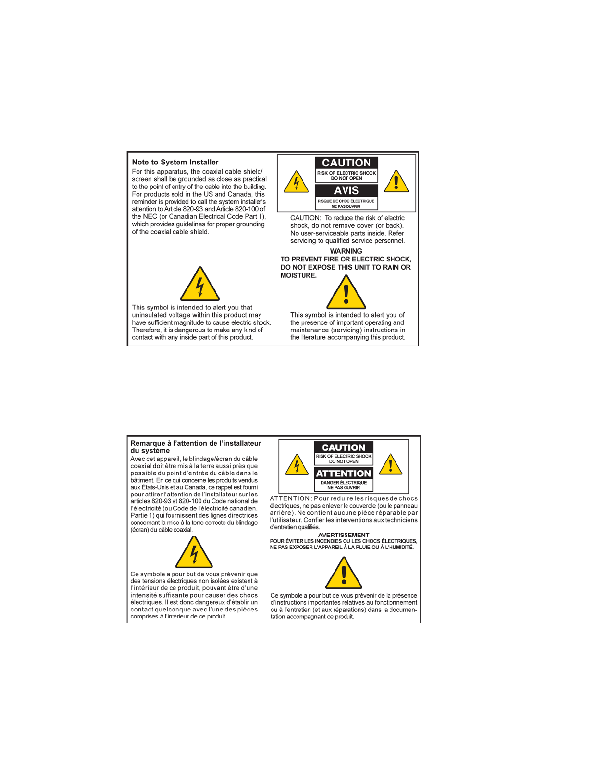
Notice to Installer s
The servicing instructions in this notice are for use by qualified service personnel only. To r ed uce the
ri sk of electric shock, do not perform any servicing other than tha t contained in the operating
instructions, unless you are qualified to do so.
Notice à l’atten t ion des installateurs d e réseaux câblés
Les instructions relatives aux interventi ons d’entreti en, fournies dans l a présente notice, s’ adressent
exclusivement au personnel technique quali fi é. Pour réduir e les risques de chocs électr iques, n’effectuer
aucune interventi on autr e que celles d écri tes dans le mod e d 'emploi et les instructions relatives au
foncti onnement, à moins que vous ne soyez quali fi é pour ce fai re.
Page 7
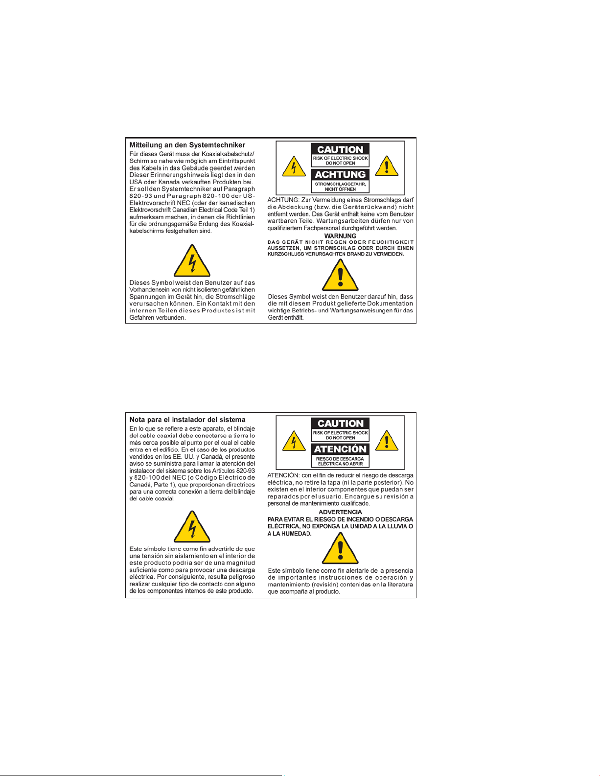
Mitteilung für CA TV -Techniker
Die in dieser Mitteilung aufgeführten Wartungsanweisungen sind ausschließlich für qualifiziertes
Fachper sonal bestimmt. Um d ie Gefahr eines el ektrischen Schlags z u r eduzier en, sollten Si e keine
Wartungsarbeiten durchführen, die nicht ausdr ückl ich in d er B edienungsanl eitung aufgeführt sind,
außer Sie sind zur Durchführung solcher Arbeiten qualifiziert.
Aviso a los instaladores de sistem as CATV
Las instr ucciones d e repara ción contenida s en el presente aviso s on pa ra uso exclusivo por par te d e
pers ona l de ma nteni miento cua lificado. Con el fin de red uci r el r iesgo de d esca rga el éctrica, no reali ce
ninguna otra operación de reparación distinta a la s conteni das en la s instrucciones de funcionamiento, a
menos que posea la cualificación necesaria para hacerlo.
20080814_Installer820_Intl
Page 8

IMPORTANT SAFETY INSTRUCTIONS
OL-30545-01 vii
IMPORTANT SAFETY INSTRUCTIONS
1)
Read these ins tr uctions.
4)
Follow all instructions.
5)
Do not use this apparatus near water.
l near any heat sources such as radiators, heat registers, stoves, or other
10)
Protect the power cord from being walked on or pinched particularly at plugs,
12)
Use only with the cart, stand, tripod, bracket, or table specified by the manufacturer,
apparatus has been exposed to rain or moisture, does not operate normally, or has
WARNING: A void e lectric shock a nd fire hazard! If this pr oduct connects to coa x ial
2) Keep these i nstructi ons.
3) Heed all warnings.
6) Clean only with dr y cloth.
7) Do not block a ny ventilation openings. Install in a ccorda nce with the ma nufacturer's
instructions.
8) Do not insta l
apparatus (including amplifiers) that produce heat.
9) Do not d efeat the safety pur pose of the pol ariz ed or ground ing-type plug. A
polarized plug has two blades with one wider than the other . A ground ing-type
plug has two blades and a third grounding prong. The wide blade or the third
prong are provided for your safety. If the provided plug does not fit into your
outl et, consult an electrician for repla cement of the obsolete outlet.
convenience recepta cl es, and the point w her e they exi t from the a pparatus.
11) Only use a ttachments/a ccessories specified by the ma nufa cturer .
or sold with the apparatus. When a cart is used, use caution when moving the
cart/apparatus combination to avoid injury from tip-over.
13) Unplug this apparatus during lightning storms or when unused for long periods of
time.
14) Refer a ll servicing to qual ified service personnel. Servicing is required when the
apparatus has been damaged in any way, such as a power-suppl y cord or plug is
damaged, liquid has been spilled or objects have fal len into the appar a tus, the
been d ropped.
P ower Source W arni ng
A label on this product indicates the correct power source for this product. Operate this product only
from a n electri ca l outl et w i th the vol tage and frequency i ndicated on the product l abel. If you are
uncertain of the type of power supply to your home or business, consult your service provider or your
local power company.
The AC inlet on the unit must remain accessible and operable at all times.
Ground the Product
cable wiring, be sure the cable system is grounded (earthed). Grounding p rovides
some protection against voltage surge s and b uilt-up static charges.
Page 9

IMPORTANT SAFETY INSTRUCTIONS
viii OL-30545-01
WARNING: Avoid e lec tr i c shoc k and fir e haz a r d! Do not overload AC p ower/ma ins,
outlets, extension cords, or integral convenience receptacles. For products that require
P rotect the P roduct from Lightni ng
In add ition to di sconnecti ng the AC power from the wa ll outlet, di sconnect the signal inputs.
Verify th e Power Source from the On/Off Power Light
When the on/off power light is not illumina ted , the a ppar atus may still be connected to the power
source. The li ght may go out when the a pparatus is turned off, r ega r dles s of w hether i t i s still plugged
into an AC power source.
Eliminate AC Power/Mains Overloads
battery power or other power sources to operate them, refer to the operating
instr uctions f or those p roducts.
Provide V entilation and Select a Location
Remove all packaging material before applying power to the product.
Do not place this apparatus on a bed, sofa, rug, or similar surface.
Do not place this apparatus on an unstable surface.
Do not insta ll this a ppar atus in an enclosure, such as a bookcase or r ack, unless the installation
provi d es proper ventilation.
Do not place entertainment devices (such as VCRs or DVDs), lamps, books, vases with liquids, or
other objects on top of this product.
Do not block ventilation openings.
Opera ting E nvi ronm ent
This product is designed for operation indoors with a temperature range from 32° to 104° F (0° to 40°C).
Each product should have adequate spacing on all sides so that the cooling air vents on the chassis are
not blocked.
Page 10

IMPORTANT SAFETY INSTRUCTIONS
OL-30545-01 ix
P rotect from E xpos ure to Moisture and Fore ign O bject s
WARNI NG: Avoid electr ic shock and fire hazard! Do not expose this product to
WARNING: Avoid ele ctr ic shock a nd f ire ha z a r d! Unp lug this p r oduct before cleaning.
Do not use a liquid cleaner or an aerosol cleaner. Do not use a magnetic/static cleaning
WARNING: A void e lectric shock a nd fire hazard! Neve r p ush ob jects through the
WARNING: Avoid e lec tr i c shoc k! Do not open the cover of this p r oduct. Op e ning or
dripping or splashing liq uids, rain, or moisture. Objects filled with liquids, such as
vases, should not be placed on this apparatus.
device (dust re mover ) to clea n this product.
op e nings in this product. For eign obje cts can cause electrical shor ts that can re sult in
electric shock or fire.
Service Warnin gs
removing the cover may e xp ose you to dangerous voltage s. If you open the cover, your
warranty will be void. This product contains no user-serviceable parts.
Check Product Safety
Upon completion of any service or r epair s to this product, the ser vi ce technician must perfor m safety
checks to determine that this product is in proper operating condition.
P rotect the P roduct W hen Movi ng It
Alwa ys d isconnect the power source w hen moving the appara tus or connecti ng or disconnecting
cabl es.
Page 11

United Sta te s FCC Complianc e
OL-30545-01 xi
United S tates FCC Compliance
Any changes or modifications not expressly approved by the party responsible for compliance could
void the user’s authority to operate this equipment.
This device has been tested and found to comply with the limits for a Class B digital device,
pursuant to part 15 of the FCC Rules. These limits are designed to provide reasonable
protection against such interference in a residential installation. This equipment generates,
uses, and can radiate radio frequency energy. If not installed and used in accordance with the
instructions, it may cause harmful interference to radio communications. However, there is
no guarantee that interference will not occur in a particular installation. If this equipment
does cause harmful interference to radio or television reception, which can be determined by
turning the equipment OFF and ON, the user is encouraged to try to correct the interference
by one or more of the followin g measures:
Reorient or relocate the receiving antenna.
Increase the separation between the equipment and receiver.
Connect the equipment into an outlet on a circuit different from that to which the
receiver is connected.
Consult the service provider or an experienced radio/television technician for help.
Any chang es or modifications not e xpre ssly approved by Cisco Systems, Inc. , could void the
user's authority to operate the equipment.
The information shown in the FCC Declaration of Conformity paragraph below is a
requirement of the FCC and is intended to supply you with information regarding the FCC
approval of this device. The phone numbers listed are for FCC-related questions only and not
intended for questions regarding the connection or operation for this device. Please contact your
service provider for any questions you may have regarding the operation or installation of this device.
De cla ration of Conform it y
This device complies with Part 15 of FCC
Rules. Operation is subject to the following
two condition s: 1) the dev ice may not cause
harmful interference, and 2) the device must
accept any interference received, including
interference that may cause undesired
operation.
DOCSIS Wireless Residential Gateway
Model(s): DPC3829 DPC3829M
Manufactured by:
Cisco Systems, Inc.
5030 Sugarloaf Parkway
Lawrenceville, Georgia 30044 USA
Canada EMI R egulation
This Class B digital apparatus complies with Canadian ICES-003.
Cet appareil numérique de la class B est conforme à la norme NMB-003 du Canada.
Page 12

United Sta te s FCC Complianc e
x ii OL-30545-01
RF Exposure Statements
Note: This device and it's antennas(s) must not be co-located or operating in conjunction with any other
antenna or transmitter except in accordance with FCC multi-transmitter product procedures.
This equipment should be installed and operated with a minimum
distance of 7.9 inches (20 cm) between the radiator and your body. For products available in
the USA/Canada market, only channels 1-11 can be operated. The selection of other channels
is not possible.
US
This system has been evaluated for RF exposure for humans in reference to ANSI C 95.1
(American National Standards Institute) limits. The evaluation was based in accordance with
FCC OET Bulletin 65C rev 01.01 in compliance with Part 2.1091 and Part 15.27. The minimum
separation distance from the antenna to general bystander is 7.9 inches (20 cm) to maintain
compliance.
Canada
This system has been evaluated for RF exposure for humans in reference to Canada Health
Code 6 (2009) limits. The evaluation was based on evaluation per RSS-102 Rev 4. The
minimum separation distance from the antenna to general bystander is 7.9 inches (20 cm) to
maintain compliance.
20100527 FCC DSL_Domest ic
Page 13
United States FCC Compliance
OL-30545-01 xiii
National Restrictions
This product is for in door use only .
USA/Canada
This system has been evaluated for RS-210. When operating this system, adhere to the
following requirements:
When operating in the band 5150-5250 MHz, the device is only for indoor use to reduce
the potential for harmful interference to co-channel mobile satellite systems.
The maximum antenna gain permitted for devices in the bands 5250-5350 MHz and 5470-
5725 MHz shall comply with the EIRP limit.
The maximum antenna gain permitted for devices in the band 5725-5825 MHz shall
comply with the EIRP limits specified for point-to-point and non point-to-point
operation as appropriate.
Users should also be advised that high-power radars are allocated as primary users (i.e.
priority users) of the bands 5250-5350 MHz and 5650-5850 MHz and that these radars
could cause interference and/or damage to LE-LAN devices.
Operation in the 5600- 5650 MHz band in the US is not permitted at this time to avoid
interference with Terminal Doppler Weather Radar systems operated by the FAA. This
requirement is applicable to systems installed indoors or outdoors. Note: Industry
Canada also restricts operation of this band per RSS-210. Systems being installed
outdoors are subject to the following restrictions:
a Systems must be professionally installed by trained qualified engineer or technicians.
b Systems must be installed per the recommended guidelines in the installation guide
for the outdoor systems.
c The use of non-approved Cisco antennas or unauthorized modifications could affe ct
the operation of the system and result in interference to the TDWR and as such the
operator could be held liable for such interference.
Page 14
United Sta te s FCC Complianc e
x iv OL-30545-01
Ce système a été évalué pour les normes radioélectriques RS-210. Lorsque vous exploitez ce
système, respectez les exigences listées ci-dessous.
Quand l'appareil est exploité dans la bande 5150-5250 MHz, il peut uniquement être
utilisé à l'intérieur pour réduire le risque de brouillage préjudiciable qui pourrait affecter
les systèmes satellites portables sur la même voie.
Le gain d'antenne maximal permis dans le cas des appareils utilisant les bandes 5250-
5350 MHz et 5470-5725 MHz doit être conforme à la limite PIRE (EIRP).
Le gain d'antenne maximal permis dans le cas des appareils utilisant la bande 5725-5825
MHz doit être conforme aux limites PIRE (EIRP) précisées pour les activités point à point
et non point à point, le cas échéant.
Les utilisateurs doivent aussi savoir que les radars haute puissance sont les utilisateurs
principaux (c.-à-d. les utilisateurs prioritaires) des bandes 5250-5350 MHz et 5650-5850
MHz et que ces appareils sont susceptibles de causer des parasites ou des dommages aux
dispositifs LE-LAN.
Le fonctionnement en 5600 - bande 5650 MHz aux Etats-Unis n'est pas autorisée à ce
moment pour éviter les interférences avec Doppler systèmes radar météorologiques
terminal exploité par la FAA. Cette exigence est applicable aux systèmes à l'intérieur ou à
l'extérieur installés. Note: Industrie Canada procède également à l'exploitation de cette
bande par RSS-210. Systèmes étant installés à l'extérieur sont soumis aux restrictions
suivantes:
a Les systèmes doivent être installés professionnellement par l'ingénieur ou technicien
formé et qualifié.
b Les systèmes doivent être installés selon les directives recommandées dans le guide
d'installation pour les systèmes extérieurs.
c L'utilisation d'antenne s non approuvée s par Cisco ou modification n on autorisée
pourrait affecter le fonctionnement du système et entraîner des interférences dans la
TDWR et en tant que telle l'opérateur peut être tenu pour responsable de cette
atteinte.
France
For 2.4 GHz, the output power is restricted to 10 mW EIRP when the product is used
outdoors in the band 2454 - 2483.5 MHz. There are no restrictions when used in other parts of
the 2.4 GHz band. Check http://www.arcep.fr/ for more details.
Pour la bande 2,4 GHz, la puissance est limitée à 10 mW en p.i.r.e. pour les équipements
utilisés en extérieur dans la bande 2454 - 2483,5 MHz. Il n'y a pas de restrictions pour des
utilisations dans d'autres parties de la bande 2,4 GHz. Consultez http://www.arcep.fr/ pour
de plus amples détails.
Italy
This product meets the National Radio Interface and the requirements specified in the
National Frequency Allocation Table for Italy. Unless this wireless LAN product is operating
within the boundaries of the owner's property, its use requires a “general authorization.”
Please check http://www.comuni cazioni.it/i t/ for more details.
Page 15

United Sta te s FCC Complianc e
OL-30545-01 xv
Questo prodotto è conforme alla specifiche di Interfaccia Radio Nazionali e rispetta il Piano
Nazionale di ripartizione delle frequenze in Italia. Se non viene installato all 'interno del
proprio fondo, l'utilizzo di prodotti Wireless LAN richiede una “Autorizzazione Generale”.
Consultare http://www.comuni cazioni.it/i t/ per maggiori dettagli.
Latvia
The outdoor usage of the 2.4 GHz band requires an authorization from the Electronic
Communications Office. Please check http://www.esd.lv for more details.
2,4 GHz frekvenču joslas izmantošanai ārpus telpām nepieciešama atļauja no Elektronisko
sakaru direkcijas. Vairāk informācijas: http://www.esd. lv.
Note: The regulatory limits for maximum output power are specified in EIRP. The EIRP level
of a device can be calculated by adding the gain of the antenna used (specified in dBi) to the
output power available at the connector (specified in dBm).
Antennas
Use only the antenna supplied with the product.
20110311_CE_Gateway
Page 16

OL-30545-01 1
1 Chapter 1
Int r oduci ng the D OC SI S
Wireless Resid ential G ateway
Purpose
This guide covers the following product models:
DPC3829 DOCSIS Wireless Residential Gateway
DPC3829M DOCSIS Wireless Residential Gateway
All features described in this guide are standard to these models of
residential ga teways unless otherwise noted. For the purpose of this
guide, whenever a feature or option applies to only a specific model,
the model number is specified. If a model number is not specified,
then the feature or option applies to both of the models.
Audience
This guide is written for the home subscriber.
Document Version
This is the first formal release of this document.
In Thi s Cha pte r
Introduction ..........................................................................................2
What's In th e Carto n? ...........................................................................3
Front Panel Description .......................................................................4
Back Panel Desc ription ........................................................................6
Page 17

Chapter 1 Introducing the DOCSIS Wireless Residential Gateway
2 OL-30545-01
Introduction
Your Wireless Residential Gatewa y meets industry standards for high-speed data
connect ivity. This residential gateway delivers data and wired (Ethernet) or wireless
gateway capabilities to connect a variety of devices in the home or small office and
support high-speed data access and cost-effective voice services, a ll in one device.
This guide provides procedures and recommendations for installing, operating, and
troubleshooting your residential gateway for high-speed Internet service. Contact
your service provider for more informa tion about subscribing t o these services.
Your new residential gateway offers the following outstanding benefits and features:
Compliant with DOCSIS 3.0, 2.0, and 1.x standards specifications to deliver
high-end performance and reliability
High performance broa dband Int ernet connectivit y to energize your online
experience
Four 1000/100/10BASE-T Ethernet ports to provide wired connectivity
802.11n Wireless Access Point
User configurable Parental Control blocks access to undesirable Internet sites
Advanced firewall technology deters hackers and protects the home network
from unauthorized access
Attractive compact design that allows for vertical, horizontal, or wall-mounted
operation
Color-coded interface ports and corresponding cables simplify installation and
setup
DOCSIS-5 compliant LED labeling and behavior provides a user and technician
friendly method to check operational status and act as a troubleshooting tool
Allows automatic software upgrades by your service provider
Page 18

What's In the Carton?
OL-30545-01 3
What's In the Carton?
When you receive your residential gateway, you should check the equipment and
accessories to verify that each item is in the carton and that each item is undamaged.
The carton contains the following items:
One DPC3829 or DPC3829M DOCSIS
Wireless Residential Gateway
One Et hernet cable ( May not be
provided with all products.)
One power ada pter (models requiring
external power supply)
One USB cable (Image may vary from
actual product. May not be provided
with all products.)
If any of these items are missing or damaged, please conta ct your service provider
for assistance.
Notes:
You need an optional cable signal splitter and additional standard RF coaxial
cables if you want to connect a VCR, a Digital Home Communications Terminal
(DHCT) or a set -top converter, or a TV to the same cable connection as your
residential ga teway.
If your product supports telephone service, cables, and other equipment needed
for telephone service must be purchased separately. Contact your service
provider to inquire about the equipment and cables you need for telephone
service.
Page 19

Chapter 1 Introducing the DOCSIS Wireless Residential Gateway
4 OL-30545-01
Front Panel Descriptio n
The front panel of your residential gateway provides LED status indicators that
indicate how well and at what state your residential gateway is operating. See
Operation of Front Panel Indicators (on page 17), for more information on front
panel LED stat us indicator functions.
1 POWER—ON, power is applied to the residential gateway.
2 DS—ON, the residential gateway is receiving data from the cable network.
3 US—ON, the residential gateway is sending data to the cable network.
4 ONLINE—ON, the residential gateway is registered on the network and fully
operational.
5 LINK —ON, the Ethernet connect ion is opera tional. BLINKING indicates that
data is being transferred over the Ethernet connection. OFF indicates that the
Et hernet connection is not connected or has been disabled by the user.
6 USB—ON, a device is connected to the USB port. BLINKING indicates that data
is being transferred over the USB connection.
7 WIRELESS ON/OFF (Optional)—Press this button to activate and turn on the
Wireless feature. This feature allows users to transfer data over the wireless
connect ion. When the WIRELESS indicator is ON, it indicates tha t the Wireless
Access Point is operational. BLINKING indicates that data is being transferred
over the wireless connection. OFF indica tes that the Wireless feature has been
disabled.
Page 20

Front Panel Description
OL-30545-01 5
8 WIRELESS SETUP—Press this button to activate the Wireless Setup feature.
This feature allows users to add new Wireless Protected Setup (WPS) complia nt
wireless clients to the home network. When the SETU P indicator is OFF (normal
condition), it indicates that the wireless setup is not active. BLINKING indicates
the user has activated wireless setup to add new wireless clients on the wireless
network.
Page 21

Chapter 1 Introducing the DOCSIS Wireless Residen t ial Gateway
6 OL-30545-01
Back Panel D escriptio n
The following illustration identifies the back panel components on the DPC3829
residential ga teways. Descriptions for each component follow the illustration.
Important: Do not connect your PC to both the Ethernet and USB ports at the same
time. Your residential gateway will not function properly if both the Ethernet and
USB ports are connected to your PC at the same time.
1 ON/OFF SWITCH (Provided only on products that carry the CE mark)—
Allows you to turn off the residential gateway without removing the power cord.
Tu rning the resident ia l gateway off using this switch ensures that the unit is
consu ming no energy.
2 POWER—Connects the residential gateway to the AC power adapter that is
provided with your residential gateway.
Important: Use only the power supply provided with your residential gateway.
3 USB (Optional for some models)—Connects to selected devices. For models that
support USB, the default is one USB port.
4 ETHERNET—Four RJ-45 Ethernet ports connect to the Ethernet port on your PC
or your home network.
5 CABLE—F-connector connect s to an active cable signal from your service
provider.
6 RESET—A momentary pressing (1-2 seconds) of this switch restarts (power
cycles ) the device. P ressing a nd holding the swit ch for more than ten seconds
first causes a reset-to-factory-default of all settings and then restarts (power
cycles) the device.
Page 22

Back Panel Descript ion
OL-30545-01 7
CAUTION:
instructed to do so by your service provider. Doing so may cause you to lose
The RESET button is for maintenance purposes only. Do not use unless
any settings you have selected.
7 MAC ADDRESS LABEL—Displays the CM a nd WAN MAC addresses for t he
residential ga teway
Page 23

OL-30545-01
2 Chapter 2
Installin g the DOCSIS Wireless
Residential Gateway
Install the Wir el ess Res idential Gateway .........................................15
Introduction
This chapter describes how to properly install the residential gateway
and t o connect the residential gateway to a computer and other
devices.
In Thi s Cha pte r
Installation P reparations ....................................................................10
8
Page 24

Chapter 2 Installing the DOCSIS Wireless Residen t ial Gateway
OL-30545-01
Installati on Prepara tio ns
Before installing the residential gateway, make sure that your system meets or
exceeds the requirements listed in this section. Also, make sure that you have
prepared your home and home devices as described in this section.
What Are the System Requirements for Internet Service?
To ensure that your residential gateway operates efficiently for high-speed Internet
service, you must have a n Internet-capable PC, Mac, or Internet a ppliance equipped
with an Ethernet port.
Note: You will also need an a ctive cable input line and an Internet connection.
What T ypes of Service Accounts Do I Need?
Depending upon the features your service provider offers, you may need to establish
one or both of the following accounts:
A high-speed Internet access account, if your residential gateway supports an
Internet connection
An account for telephone service, if your residential gateway supports digital
telephone service
Refer to one of the following topics to learn more about the types of service accounts
that you may need to establish.
High-Speed Internet Access Account
If you do not have a high-speed Internet access account, your service provider will
set up your account and become your Internet Service Provider (ISP). Internet access
enables you to send and receive e-mail, access the World Wide Web, and receive
other Internet services.
You will need to give your service provider information about the residential
gatewa y in order to use the high-speed internet feature that this product offers. Refer
to Information Your Service Provider Needs (on p age 11) to learn how to locate the
information your service provider needs to establish a high-speed Internet access
account for the residential gateway
If you ha ve an existing high-speed Internet access a ccount, you will need to give
your service provider the serial number and MAC address of the residential gateway
in order to use the high-speed internet feature that this product offers. Refer to
Information Your Service Provider Needs (on pa ge 11) to learn how to locate this
information.
9
Page 25

Insta llation Pre para tions
OL-30545-01
Information Your Serv ice Prov ider Needs
DPC3829M
You will need to give your service provider the following information, which is
printed on the bar code label attached to the device:
The Serial Number (S/N) of the residential gateway. The serial number consists
of a series of nine digits.
The Media Access Control (CM MAC) address of the residential gatewa y. The
CM MAC address consists of a series of 12 alphanumeric characters.
The Media Access Control (MAC) address of the residential gatewa y media
terminal adapter (MTA MAC). The MTA MAC address consists of a series of 12
alphanumeric chara cters.
The following illustration shows a typical bar coded label; the image may vary from
the label on the actual product.
Write down these numbers in the spaces provided:
Serial Number _______________________
CM MAC MAC Address ________________________
MTA MAC Address ________________________
I Already Hav e a High-Speed Internet Access Account
Where Is the Best Location for My W ireless Residential G ateway?
The ideal location for your residential gateway is where it has access to outlets and
other devices. Think about the layout of your home or office, and consult with your
service provider to select the best location for your residential gateway. Read this
user guide thoroughly before you decide where to place your residential gateway.
Consider these recommendations:
Choose a location close to your computer if you will also use the residential
10
Page 26

Chapter 2 Inst all ing the DOCS IS Wireless Residen t ial Gateway
OL-30545-01
gateway for high-speed Internet service.
Choose a location tha t is near an existing RF coaxia l connection to eliminate the
need for an additional RF coaxial outlet.
Choose a location that is relatively protected from accidental disturbance or
harm, such as a closet, basement, or other protected a rea.
Choose a location so that there is plenty of room to guide the cables away from
the residential gateway without straining or crimping them.
Choose a location that allows adequate ventilation around the residential
gateway.
How Do I Mount the Residential Gateway on a Wall? (Optional)
If you wish, you can mount the residential gat eway to a wall. This section describes
how to mount the residential gateway to a wall, and includes a list of equipment you
will need along with suggestions for choosing an appropriate place to mount t he
residential ga teway.
Se le c t an Appropriat e P la c e t o Mount t he Res ide ntial Gateway
You may mount the residential gateway to a wall that is made of cement, wood, or
drywall. When choosing an a ppropria te mounting p la ce, refer to the following
recommendations:
Ensure that the mounting locat ion is f ree of obstructions on all sides, and the
cables should be able to easily reach the residential gateway without strain.
Leave sufficient clearance between the bottom of the residential gateway and any
flooring or shelving underneath to allow access to cabling.
Allow enough slack in all cables so that the residential gateway can be removed
for any required maintenance without disconnecting the cables.
Choose a location that allows adequate ventilation around the residential
gateway.
Equipment Ne e de d
Verify that you ha ve the following items that you will need to mount the residential
gateway:
Two wall anchors for #8 x 1-inch screws
Two #8 x 1-inch pan head sheet metal screws
Drill with a 3/16-in. wood or masonry bit, as appropriate for the wall
composition
A copy of the wall-mounting illust ra tions shown on the following pages
11
Page 27

Insta llation Pre para tions
OL-30545-01
Locat ion a nd Dimens ions of t he Wa ll-Mount ing S lot s
The following illustration shows the location and dimensions of the wall-mounting
slots on the bottom of the residential gateway. Use this illustration as a guide for
mounting the residential gateway to the wall.
Note: Image not to scale.
Mounting the Re s ide nt ia l G a t e w a y on a Wa ll
1 Using a drill with a 3/16-inch bit, drill two holes at the sa me height and 4 inches
apa rt.
Note: The p receding gra phic illustrates t he locat ion of the mounting holes on the
back of the residential gateway.
2 Are you mounting the residential gateway into a drywall or concrete surface
where a wooden stud is available?
If yes, go to step 3.
If no, drive the anchor bolt s into the wa ll, and install the mounting screws
into the anchor bolts; leave a gap of about 1/4-inch between the screw head
and the wall. Then, go to step 4.
12
Page 28

Chapter 2 Inst all ing the DOCS IS Wireless Residen t ial Gateway
OL-30545-01
3 Install t he mou nting screws into the wall; leave a gap of about 1/4-inch between
the screw head and t he wall. Then, go to step 4.
4 Verify that no cables or wires are connected to the residential gateway.
5 Lift the residential gateway into position. Slip the large end of both mounting
slots (located in the back of the residentia l gateway) over the mounting screws,
and t hen slide the residentia l gateway down until the narrow end of the keyhole
slot contacts the screw shaft.
Important: Verify that the mounting screws securely support the residential
gatewa y before you release the unit.
13
Page 29

I n st all th e W irel ess Residen t ial Gateway
OL-30545-01
Install the Wireless R esidenti al G ateway
This section describes how to connect your residential gatewa y to support the
services that the residential gateway offers.
Connect the Wi reless Residential Gateway
The following ins talla tion procedure ensures proper setu p and configuration for the
residential ga teway.
1 Choose an appropriate and safe location to install the residential gateway (close
to a power source, an active cable connection, and your PC-if using high-speed
Internet). For assistance, go to Where Is the Best Location for My Wireless
Residential Gateway? (on p age 11).
WARNING:
To avoid personal injury, follow the installation instructions in the exact
order shown.
Wiring and connections must be properly insulated to prevent electrical
shock.
Disconnect power from the residential gateway before attempting to
connect to any device.
2 Power off your P C a nd other net working device; then, unplug them from the
power source.
3 Connect the active RF coaxia l cable from your service provider to the coa x
connector la beled CABLE on the back of the residential gateway.
Note: To connect a TV, DHCT, set-top, or VCR from the same cable connection,
you will need to install a cable signal splitter (not included). Always check with
your service provider before using a splitter as a splitter ma y degrade the s ignal.
4 Connect your PC to t he residentia l gateway using eit her of the following
connect ions:
Ethernet Connection: Locate the yellow Ethernet cable, connect one end of
the Et hernet cable to the Et hernet port on your PC, a nd connect the other end
to the yellow ETHERNET port on the back of the residentia l gateway.
Note: To install more Ethernet devices than ports provided on the residential
gatewa y, use an external mulit-port Ethernet switch(s).
Wireless: Make sure that your wireless device is powered up. You will need
to associate your wireless device with the wireless residential gateway once
the residential gateway is operational. Follow the directions provided for
your wireless device for associating with a wireless access point. If the
residential gateway has a WIRELESS ON/OFF button, make sure that
WIRELESS is enabled by confirming that the ON/OFF indicator is ON. If t he
indicator is OFF, press the ON/OFF button to enable the WIRELESS feature.
14
Page 30

Chapter 2 Inst all ing the DOCS IS Wireless Residen t ial Gateway
OL-30545-01
More information about the factory default configuration of your wireless
residential gateway can be found later in this guide in Configure Wireless
Settings.
5 Locate the AC power cord provided with your residentia l ga teway. Insert one
end of t he power cord into the AC connector on the back of the residential
gatewa y. Then, plug the AC power cord into an AC outlet to power-up the
residential gateway. The residential gateway will perform an automatic search to
locate a nd sign on to the broadband data net work. This p rocess ma y ta ke up t o 2 5 minutes. The residential gateway will be ready for use when the POWER, DS,
US, and ONLINE LEDs on the front panel of the residential gatewa y stop
blinking and rema in on continuously.
6 Plug in and power on your PC and ot her home network devices. The LINK LED
on the residential gatewa y corresponding to the connected devices should be on
or blinking.
7 Once your residential gateway is online, most Internet devices will have
immediate Internet access.
Note: If your PC does not have Internet access, refer to How Can I Make Sure
TCP/IP Is Configured Correctly on my PC? (see "How Do I Configure TCP/IP
Protocol?" on pa ge 24) for information on how to configure your PC for TCP/IP.
For Internet devices other than PCs, refer to the DHCP or IP Address
configuration section of t he User Guide or O perations Ma nual for those devices.
15
Page 31

OL-30545-01
3 Chapter 3
Oper ation of Front Panel
Indicators
Special Co nditio ns ..............................................................................21
Introduction
This section describes the behavior of the front p anel indicators when
the residential gateway is first powered up, during normal operations,
and in special conditions.
In Thi s Cha pte r
Initial Power Up, Calibration, and Registration (AC Power
Applied) ..............................................................................................18
Normal Op era tio ns (AC Pow er Applied) ........................................20
16
Page 32

Chapter 3 Operation of Front Panel Indicators
OL-30545-01
Initial Power Up, C alibratio n, and Registrat ion (A C
Registration
Front Panel
Self
Downstream
Downstream
Ranging
Requesting IP
Request High Speed
1
POWER
On
On
On
On
On
On 2 DS
On
Blin king
On
On
On
On
3
US
On
Off
Off
Blin king
On
On
4
ONLINE
On
Off
Off
Off
Off
Blin king
5
LINK
On
Off, On, or
Off, On, or
Off, On, or
Off, On, or
Off, On, or Blinking
6
USB
On
Off, On, or
On or Blinking
On or
On or Blinking
On or Blinking
7
WIRELESS
Off
On or Blinking
On or Blinking
On or
On or Blinking
On or Blinking
8
WIRELESS
Off
On or Blinking
On or Blinking
On or
On or Blinking
On or Blinking
Registration
(continued)
Front Panel
Data N etwork
1
POWER
On 2 DS
On 3 US
On 4 ONLINE
On
5
LINK
On
Power Applied)
The following chart illustrates the sequence of steps a nd the corresponding
app ea ra nce of the residential ga tewa y front pa nel LED status indica tors during
power up, calibration, and registration on the network when AC power is a pplied to
the residential gateway. Use this chart to troubleshoot the power up, calibration, and
registration process of your residential gateway.
Note: After the residential gateway completes Step 7 (Data Network Registration
Complete), the residential gateway proceeds immediately to Normal Operations. See
Normal Operations (AC Power Applied) (on page 20).
Front Pa nel LED Sta tus Indic ators Duri ng I nitia l P ow er Up, Ca libra tion, a nd
Part 1, High Speed Data Registration
Step: 1 2 3 4 5 6
Indicator
ON/ OFF
SETUP
Tes t
Scan
Blin king
Blin king
Signal Lock
Blin king
Blin king
Blin king
Blin king
Blin king
Address
Blin king
Front Pa nel LED Sta tus
Indic ators During Ini tial Power
Up, Cal ibra tion, and
High Spe ed Data Re gistra tion
Data Provisioning
File
Step: 7
Indicator
17
Registration
Complete
Page 33

Initial Power U p, Calibra tion, and Re gist r at ion ( AC Power A pplied)
OL-30545-01
6
USB
On or Blinking
7
WIRELESS
On or Blinking
8
WIRELESS
Off
ON/ OFF
SETUP
18
Page 34

Chapter 3 Operation of Front Panel Indicators
OL-30545-01
Norm al O per ation s ( A C P ow er Applied)
When wireless setup is active to add new wireless
The following chart illustrates the appearance of the residential gatewa y front pa nel
LED status indicators during normal operations when AC power is applied to the
gateway.
Front Panel LED Status Indicators During Normal Conditions
Fr ont Pa ne l Indicator Normal Ope ra tions
1
POWER On
2
DS On
3
US On
4
ONLINE On
5
LINK
6
USB
On - When a single device is connected to the Ethernet
port and no data is being sent to or from the residential
gateway
Blinks - When only one Ethernet device is connected and
data is being transferred between the consumer premise
equipment (CPE) and the wireless home gateway
Off - When no devices are connected to the Ethernet ports
On - When a single device is connected to the USB port
and no data is being sent to or from the modem
Blinks - When only one USB device is connected and data
is being transferred between the consumer premise
equipment (CPE) and the wireless home gateway
Off - When no devices are connected to the USB ports
7
8
WIRELESS
ON/OFF
WIRELESS
SETUP
On - When the wireless access point is enabled and
operational
Blinks - When data is being transferred between the CPE
and the wireless home gateway
Off - When the wireless access point is disabled by the
user
Off - When wireless setup is not active
Blinks -
clients on the wireless network
Note: In a ddition to the s tatus shown in the p revious table, s ome service providers
use color-coded LEDs to indicate detailed channel bonding and data link status. For
additional information about color-coded LEDs, check with your service provider.
19
Page 35

Special Conditions
OL-30545-01
Special C ondition s
The following cha rt describes the appearance of the residential gateway front panel
LED sta tus indicators during sp ecial conditions to show when you have been denied
network access.
Front Panel LED Status Indicators During Special Conditions
Fr ont Pa ne l Indicator Network Access Denied
1
POWER Slow Blinking
2
DS Slow Blinking
3
US Slow Blinking
4
ONLINE Slow Blinking
5
LINK Slow Blinking
(once per second)
(once per second)
(once per second)
(once per second)
(once per second)
6
USB Slow Blinking
(once per second)
7
8
WIRELESS
ON/OFF
WIRELESS
SETUP
Slow Blinking
(once per second)
Slow Blinking
(once per second)
20
Page 36

OL-30545-01
This chapter describes the most common issues that may occur after
4 Chapter 4
Troubleshooting t he DOCSIS
Wireless Resid ential G ateway
Tips for Improv ed Performa nce ........................................................30
Introduction
the residential gateway is installed and provides possible solutions
and tips for improved performance of the residential gateway.
In Thi s Cha pte r
Fre que nt ly Ask ed Questions .............................................................24
Common Troubleshooting Issues .....................................................29
21
Page 37

Chapter 4 Troub leshooti ng the DOCSIS Wirel ess R esident ial Gateway
OL-30545-01
Frequently Asked Q uestions
This section provides answers to common questions about the residential gateway.
How Do I Conf igure TC P /I P Protoc ol?
To configure TCP/IP protocol, you need to have an Ethernet Network Interface Card
(NIC) with TCP/IP communications protocol installed on your system. TCP/IP is a
communications protocol used to access the Internet. This sect ion cont ains
instructions for configuring TCP/ IP on your Internet devices to operate with the
residential gatewa y in Microsoft Windows or Macintosh environment s.
TCP/IP protocol in a Microsoft Windows environment is different for each
operating system. Follow the appropriate instructions in this section for your
operating system.
Configuring TCP/IP on Window s 7 Sy stems
1 Open Network Connections by clicking the Start button, and then clicking
Control Panel.
2 In the Search box, t ype adapter, and then, under Network and Sharing Center,
click View network connections.
3 Right-click the connection that you wa nt to change, and then click Properties. If
you are prompted for an administrator password or confirmation, type the
password or provide confirmation. The Local Area Connection Properties
window opens.
4 Click the Networking tab.
22
5 Under This connection uses the following items, click either Internet Protocol
Version 4 (TCP/IPv4) or Internet Protocol Version 6 (TCP/IPv6), and then click
Properties.
6 To specify IPv4 IP address settings, do one of the following:
To get IP settings automatically using DHCP, click Obtain an IP address
automatically, a nd then click OK.
To specify an IP address, click Use the following IP address, a nd then, in the
IP address, Subnet mask, a nd Default gateway boxes, type the IP address
settings.
7 To specify IPv6 IP address settings, do one of the following:
To get IP settings automatically using DHCP, click Obtain an IPv6 address
automatically, a nd then click OK.
To specify an IP address, click Use the following IPv6 address, and then, in
the IPv6 address, Subnet prefix length, and the Default gateway boxes, type
the IP address settings.
8 To specify DNS server address settings, do one of the following:
Page 38

Frequently Asked Questions
OL-30545-01
To get a DNS server address automatically using DHCP, click Obtain DNS
server address automatically, and then click OK.
To specify a DNS server address, click Use the following DNS server
addresses, and t hen, in the Preferred DNS server and Alternate DNS server
boxes, type the addresses of the primary and secondary D NS servers.
9 To cha nge advanced DNS, WINS, and IP settings, click Advanced.
10 When you a re finished, click OK.
11 Try to access the Internet. If you cannot access the Internet, contact your service
provider for further assistance.
Configuring TCP/IP on Windows XP Sy stems
1 Click Start, and depending on your Start menu set up, choose one of the
following options:
If you are using the Windows XP Default Start Menu, select Connect to,
choose Show all connections, and then go t o step 2.
If you are using the Windows XP Classic Start Menu, select Settings, choose
Network Connections, click Local Area Connection, and then go t o st ep 3.
2 Double-click the Local Area Connection icon in t he LAN or High-Speed Internet
section of t he Network Connections window.
3 Click Properties in the Loca l A rea Connection Status window.
4 Click Internet Protocol (TCP/IP), and then click Properties in the Local Area
Connect ion Properties window.
5 Select both Obtain an IP address automatically and Obtain DNS server address
automatically in the Internet Protocol (TCP/IP) Properties window, a nd t hen
click OK.
6 Click Yes to restart your computer when the Local Network window opens. The
computer restarts. The TCP/IP protocol is now configured on your PC, and your
Ethernet devices are ready for use.
7 Try to access the Internet. If you cannot access the Internet, contact your service
provider for further assistance.
Configuring TCP/IP on Macintosh Sy stems
1 Click the Apple icon in the upp er-left corner of the Finder. Scroll down t o
Control Panels, a nd then click TCP/IP.
2 Click Edit on the Finder at the top of the screen. Scroll down to the bottom of the
menu, and then click User Mode.
3 Click Advanced in the User Mode window, and then click OK.
4 Click the Up/Down selector arrows located to the right of the Connect Via
section of the TCP/I P window, and then click Using DHCP Server.
5 Click Options in the TCP/IP window, and then click Active in the TCP/IP
Options window.
23
Page 39

Chapter 4 Troub leshooti ng the DOCSIS Wirel ess R esident ial Gateway
OL-30545-01
Note: Make sure that the Load only when needed option is unch ecked .
6 Verify that the Use 802.3 option located in t he upper-right corner of the TCP/IP
window is unchecked. If there is a check mark in the opt ion, uncheck the option,
and t hen click Info in the lower-left corner.
7 Is there a Hardware Address listed in this window?
If yes, click OK. To close the TCP/IP Control Panel window, click File, a nd
then scroll down to click Close. You have completed this procedure.
If no, you must power off your Macintosh.
8 With the power off, simultaneously press and hold down the Command
(Apple), Option, P, a nd R keys on your keyboard. Keeping those keys pressed
down, power on you r Macintosh but do not release these keys until you hea r the
Apple chime at least three times, then release the keys and let the computer
restart.
9 When your computer fully reboots, repeat steps 1 through 7 to verify that all
TCP/IP settings are correct. If your computer still does not have a Hardware
Address, contact your authorized Apple dealer or Apple technical support center
for fu rther assistance.
How Do I Rene w the I P Addres s on My P C ?
If your PC cannot access the Internet after the residentia l gateway is online, it is
possible that your PC did not renew its IP address. Follow the appropriate
instructions in this section for your operat ing sys tem to renew the IP address on
your PC.
Renew ing the IP Address on Windows 7 Sy stems
1 Click the Windows Start button.
2 Type cmd in the Search box. The cmd window opens.
3 Type ipconfig /renew and press Enter to renew the IP address of the computer.
Renew ing the IP Address on Windows XP Sy stems
1 Click Start, a nd then click Run. The Run window opens.
2 Type cmd in the Open field and click OK. A window with a command prompt
opens.
3 Type ipconfig /release at the C:/ prompt and press Enter. The system releases
the IP address.
4 Type ipconfig /renew at the C:/ prompt and press Enter. The system displays a
new IP address.
5 Click the X in the upper-right corner of the window t o close the Command
Prompt window. You have completed this procedure.
Note: If you cannot access the Internet, contact your service provider for further
assistance.
24
Page 40

Frequently Asked Questions
OL-30545-01
Renew ing the IP Address on Macintosh Sy stems
1 Close all open programs.
2 Open your Preferences folder.
3 Drag the tcp/ip preferences file to the Trash.
4 Close all open windows and emp ty the Trash.
5 Restart your computer.
6 As your computer starts, simultaneously press and hold down the Command
(Apple), Option, P, a nd R keys on your keyboard. Keeping those keys pressed
down, power on your Macintosh but do not release these keys until you hea r t he
Apple chime at least three times; then, release the keys and let the computer
restart.
7 When your computer fully reboots, click the Apple icon in t he u pper-left corner
of the Finder. Scroll down to Control Panels, a nd then click TCP/IP.
8 Click Edit on the Finder at the top of the screen. Scroll down to the bottom of the
menu, and then click User Mode.
9 Click Advanced in the User Mode window, and then click OK.
10 Click the Up/Down selector arrows loca ted to the right of the Connect Via
section of the TCP/I P window, and then click Using DHCP Server.
11 Click Options in the TCP/IP window, and then click Active in the TCP/IP
Options window.
Note: In some cases, the Load only when needed option does not appear. If it
appears, select the option. A check mark appears in the option.
12 Verify that the Use 802.3 option located in t he upper-right corner of the TCP/IP
window is not selected. If there is a check mark in the option, select the option to
clear the check mark, and then click Info in the lower-left corner.
13 Is there a Hardware Address listed in this window?
If yes, click OK. To close the TCP/IP Control Panel window, click File, a nd
then scroll down to click Close.
If no, repeat these instructions from step 6.
14 Reboot your computer.
What if I Don't Subscribe to Cable TV?
If cable TV is available in your area, data service may be made available with or
without subscribing to cable TV service. Contact your local service provider for
complete information on cable services, including high-speed Internet access.
25
Page 41

Chapter 4 Troub leshooti ng the DOCSIS Wirel ess R esident ial Gateway
OL-30545-01
How Do I A rrange f or Insta lla tion?
Call your service provider to inquire about professional installation. A professional
installation ensures proper cable connection to the residential gateway and to your
PC, and it ensures the proper configurat ion of all hardware and software settings.
Contact your service provider for more information about installation.
How Does the Wireless Residential Gateway Connect to My C omputer?
The residential gateway connects to the 10/100/1000BASE-T Ethernet port on your
PC. To use the Ethernet interface, Ethernet cards available from your local PC or
office supply retailer, or from you r service provider. For best performance over an
Et hernet connection, your PC should be equipped with a Giga bit Ethernet card.
Af ter My Wireless Residential Gateway Is Connected, How Do I Access the Internet?
Your local service provider becomes your Internet Service Provider (ISP). They offer
a wide range of services including e-mail, chat, news, and information services. Your
service provider will provide the software you will need.
Can I W atch TV and Surf the Internet at the Sam e Tim e?
Absolutely! If you subscribe to cable television service, you can watch TV and use
your residentia l ga teway at the same time by connecting your TV and your
residential gateway to the cable network using an optional cable signal splitter.
26
Page 42

Common Troubleshooting Issue s
OL-30545-01
Common Trouble shooting Issues
This section describes common problems and offers solutions.
I don't understand the front panel status indicators
See Operation of Front Panel Indicators (on page 17), for more detailed information
on front panel LED stat us indicator opera tion and function.
The Wi reless Residential Gateway does not register an E thernet connection
Try one of the following solutions:
Verify that your comput er ha s an Ethernet card and t hat the Ethernet driver
software is properly installed. If you purchase and install an Ethernet card,
follow the installation instructions very carefully.
Verify the status of the front panel status indicator lights.
The Wi reless Residential Gateway does not register an E thernet connec tion af ter connec ting to a hub
If you are connecting multiple PCs to the residential gateway, you should first
connect the residential gat eway to the uplink port of the hu b using the correct
crossover cable. The LINK LED of the hub will illuminate continuously.
The Wireless Residential Gateway does not register a cable conn ect io n
The residential gateway works wit h a sta ndard, 75-ohm, RF coaxial cable. If you are
using a different cable, your residential gateway will not function properly. Contact
your service provider to determine whether you are using the correct cable.
27
Page 43

Chapter 4 Trou b leshooti ng the DOCSIS Wirel ess R esident ial Gateway
OL-30545-01
Tips for Improved Performance
If your residential gateway does not perform as expected, the following tips may
help. If you need further assistance, contact your service provider.
Verify that the plug to your residential gatewa y AC power is properly inserted
into an electrical outlet.
Verify that your residential gateway AC power cord is not plugged into a n
electrical outlet that is controlled by a wall switch. If a wall switch controls the
electrical outlet, make sure the switch is in the ON position.
Verify that the ONLINE LED status indica t or on the front panel of your
residential ga teway is illuminated.
Verify that your cable service is active and that it supports two-way service.
Verify that all cables are properly connected, and that you are using the correct
cables.
If you are using the Ethernet connection, verify tha t your TCP/IP is properly
installed and configured.
Verify that you have called your service provider and given them the serial
number and MAC address of your residential gateway.
If you are using a cable signal splitter so that you can connect the residential
gateway to other devices, remove the splitter and reconnect the cables so that the
residential ga teway is connected directly to the cable input. If the residential
gatewa y now functions properly, the cable signal splitter may be defective and
ma y need to be replaced.
If you are connected to your PC with an Ethernet connection, your PC should be
equipped with a Gigabit Ethernet card for best performance.
28
Page 44

OL-30545-01
Introduction
5 Chapter 5
Customer Information
If you have technical questions, ca ll Cisco Services for assistance.
Follow the menu options to speak with a service engineer.
Access your company's extranet site to view or order additional
technical publications. For a ccessing inst ructions, contact the
representative who handles your account. Check your extranet site
often as the informa tion is updat ed frequently.
29
Page 45

OL-30545-01
Index
A
access ing the Internet • 28
accessories • 3
C
cable service • 27
connections
description of • 6
to compu ter • 28
E
Ethernet • 29
exposure to moisture • viii
F
features, pr o duct • 3
I
indicators
b eha vi or • 18, 20, 21
des cribed • 4
opera tion of • 17
installation
professional • 28
installation requirements
minimum system requirements • 10
ventilation • viii
Internet
how to access • 28
surfing while wa tch ing T V • 2 8
unable to access • 26
IP add res s, renew ing • 27
L
LED s • 4, 18, 20, 21
location
selecting • viii, 11
power swit c h • 6
pr oduct • 2
P
performance, tips to improve • 30
product
accessories • 3
features • 2
ov er v iew • 2
S
s afe ty ins tru c tions • vi i
gr ound product • vii i
system requirement s • 10
T
TCP/IP
configuring for Macintosh systems • 25
configuring for Windows XP • 25
troubleshooting • 23
U
u npac ki ng • 3
USB • 3, 28
V
ventilation requ irements • viii
Voice settings
LED s • 4, 18, 20, 21
W
wall mounting
instructions • 13
slots • 13
O
overview
30
Page 46

Ameri cas H eadquarters
http://www.cisco.com
This document includes various trademarks of Cisco Systems, Inc. Please see the Notices
Product and service availability are subject to change without notice.
© 2013 Cisco and/or its affiliates. All rights reserved.
Cisco Systems, Inc.
170 West Tasman Drive
San Jose, CA 95134-1706
USA
section of this document for a list of the Cisco Systems, Inc. trademarks used in this
document.
Tel: +1-408 526-4000
+1-800 553-6387
Fax: +1-408 527-0883
Octo ber 2013
Part Number OL-30545-01
 Loading...