

Page 1
INSTRUCTIONS
Cat.
No.
8119
A
October,
1981
WS4S
UT
- 1
iiMmr
Page 2
r -
,X
'
•-.'
^ -T
I'l
^•-
xt
-'j
•! ^ : •
.
Page 3
(i
i:i?)Cz
WS42/UTS
i
••
S
'X
«••••
BlSau-'^
Vcm<n\^i}^tz 2
ffiUWlt
3-Ka>««tSS®
—^'—Icov^T
^-•y-t
SiKiX-f
ttS!«ttl3®
—^'—O
t
ywy'f
x7
)S')«v>±(Oitg
ffliit#
-/i-
f-y
K5«ti|iitgr«ii!i!
^I)y
ycoiR
h o v Y 4
;5lJiiWS42l^fflmBJ?t=(Cat.
1
I
i
•H'llt
xtgy^E
No. 8115) ^
r'^i
</.:'$
••
v^„
t<
3
6-7
~5
fl
2
2
3
3
4
4
5
7
^'-coaiaijiKjrafiti
ttffl±(oaa:
*-e)'j®<7)i9a
Jt/X
fiy
fiy
ty
yu-y^
•
^/X
xiliiiiBF
XX
h a —? 11
xffiaffiffl
xft^fS:®
xcor&i-> 12
Xy>'^-
ii%ffii;y<-y(2)SSa
T^,18i)^r
T=ftWix. 13
^fL'i
EHrXi'-lrZiim^
mt<nfX^-tzXhmSi,
I)
^gcoawt
;
^-:S'-<ni^fRlYSM
English edition
starts
from
10-12
13-14
15-16
17^
page
9
9
10
10
12
12
17
13
15
16
21.
] —
Page 4
WS42/UT5
mt/c.
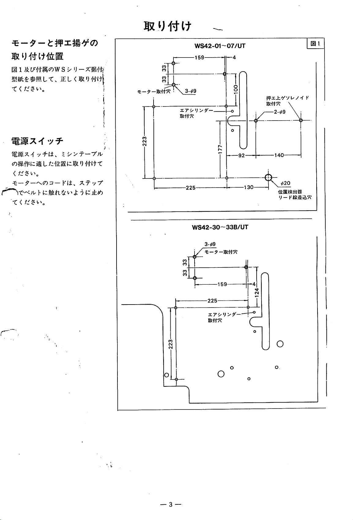
«ffi(7)jgv>3>
ifTlf^«-T-»l01iLii-o
sfeMij-av>«^-:>tt#,
oa>TV-('•••-*«#,
r-,
}i|ii(±,
n.m.9y
I-d-v-a',
u<ri^&.mw±,
ii±nc±ifT(ft:'»
^9<),
VV^*'±i")
ai".
^tih'^-'&v'V/^<n±
s+tswTf^oibn,
tt.
m^^litib
o
WS42/UT$
'j
-^a:c#w
to
^-;5'-(±.
i-Xi,
to
7J\0
WS42/UT=x>{i,
f^?ij:WS42-01X356/UT3
L
s 42 = X > tcj:o
-cM$
M<7)tl£/±®.CA'^0^CJ:oT.
i'>ymxK.'Y-i^t
T'E'iSJo
"Ct^TK
L ^"t"o
n-c
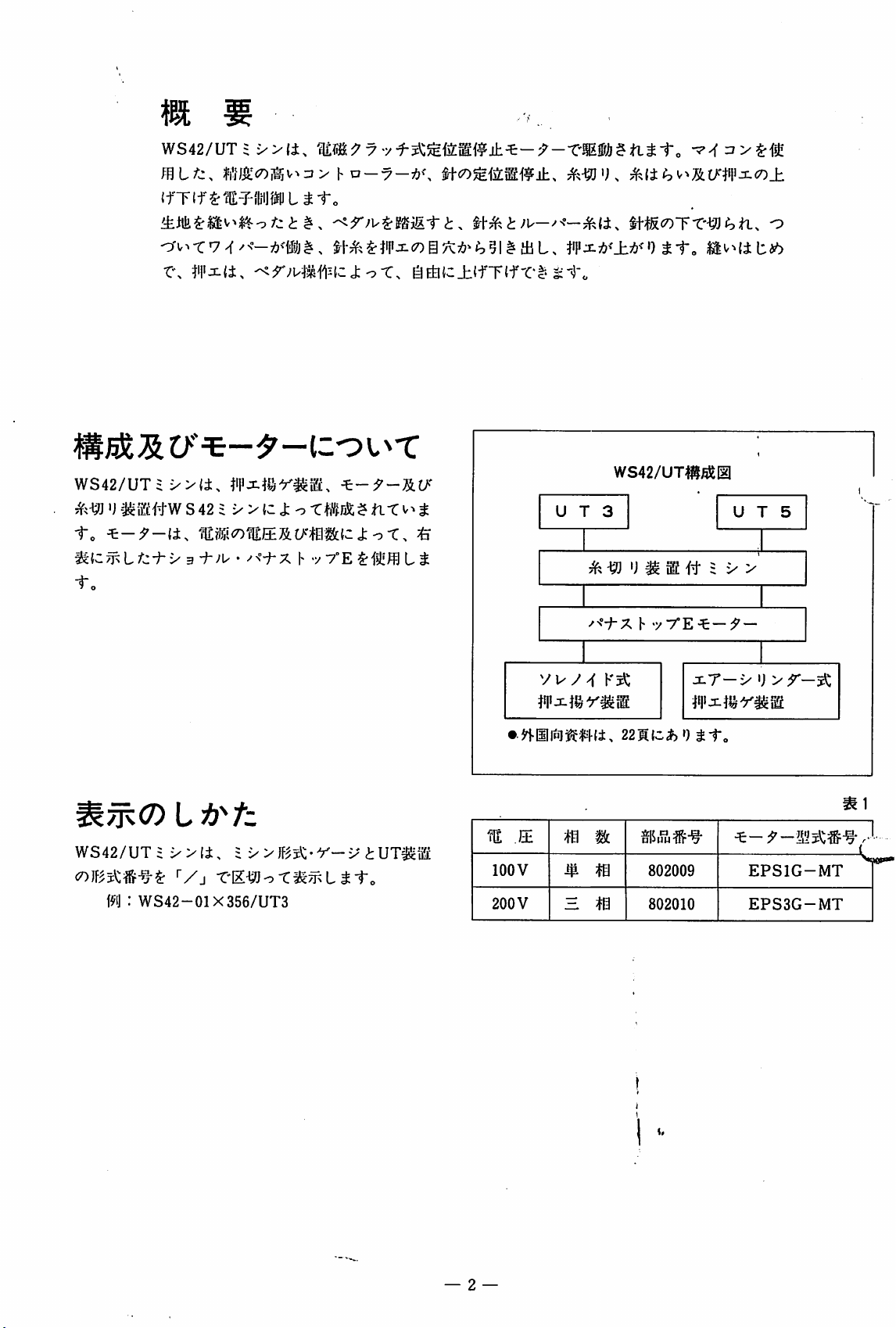
WS42/UT4#^Iil
t
U T 3
UTS
^
'J ^ = X >
h
m
lOOV
200
BE
V
vv-y
^
ffl %.
t0
H
•yT'E^—y
jiT-v
Wx-v^Ymm.
802009
802010
—
'j
>r-^
EPSIG-MT
EPS3G-MT
— 2 —
Page 5
0 1 &tA-#«cOW S xI)-XJEflv
MSft«•#ffiLT.
IE L < flit') Wl
®i
u
-rf
sTT
• \
It
WS42-01~07/UT
-159-
3-09
—^
-
1
r\
o
o
i'?j:±yvuy-f
K
<^PM¥iz
<
X <
-y
f-(i.
mifz
h
ic:fellah-4*
im
=X>T
(3M•)#{
Pit,
v-^J; n
—7';u
t r
T^f^V't
liZl±ib
•
®i#7v:
x7">'j>y-
|~o
—
2-09
G
-225-
WS42-30~33B/UT
3-09
s T
r>.
r«-
Nw/
92
-130 ^
6-
-140-
X «^20
'J -
K#j!^ii7C
+ T
-159-
r'^
-225-
u
xTv'j >^-—h®
o
O
O
— 3
Page 6
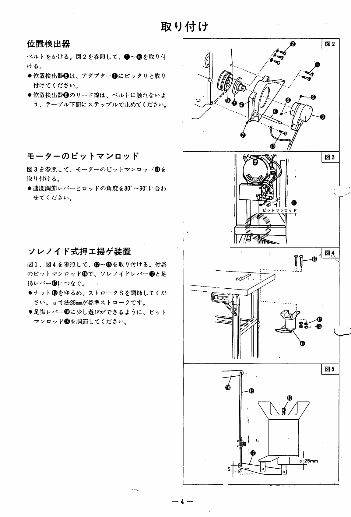
(t^o
Hifx
• \) -
9 > T
^ ^
0
3^#i!nLr,
ifstOfW^o
• a -y
•^X<
y
—7'>'uTM{-
fz^^\
uy-f
<
V^„
—(7)If
»yhvy
^-y-cotr-y
KHilfi.
X T
-^/u
••/
7°;uT'±i^'C
•
Kc7)^/g^80'-90'
h J:
<
»y
K
h-^>D-y
^•'o
@
K®^
111.
III4^#ML-C,
c7)try |- "7 > a v
®{co3i'<'o
• -h y X h a
$ a i>i25mra7!?^1l^i?iX h o - y
t
Jii!.jii
U/<-®lC'>L3it>"7(J^'T'^ ^
-7>a.y
K^T',
K®^ril.^0iiL-C<
y u / K u
—yS^:rD.^fiNLr
r'to
cfc-^{C,
—®tJE.
</c'
t'-y
h
r
7.
a:25mm
Page 7
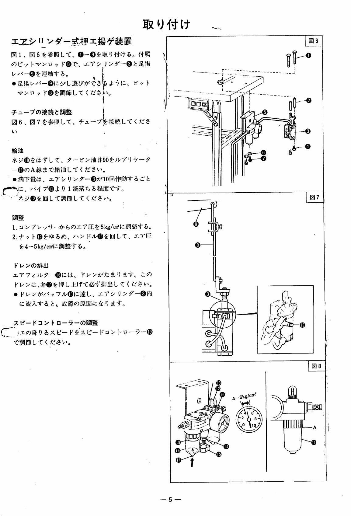
xx.*>
HI,
^0 f v
U/<—©$:
• J:
•7>oy
•f
a-7'roj55»tMS
H6.
v-k
$n/A
^^x®^(±TL-C.
—®£7)
•
?itiTl:li.
"
H6^#!fflLT.
iijiloi"
K®i^i^6DLT<
H7
4#!fflLt.
A^
j:.T
0~®SrllX')#lt2)o
KOT'.
^ o
JiT
X 'J > ^
+i-7"^«ML-C<
r^-b'^tilittgo^^urg
L*C<
/c'^
V
X 'J >
r-©;:?a0111Mfj1"
I
I
• >^x®^IllL-CHf«1r^iL-C</c'$v^„
HR
f-y
^ - b
p®
h
••^1
p
OV
1. 3 > 7°!^
2.-b-y
$"4~5kg/cirf(ClHl^Mi"-^o
K
^>'<7)^^itl
jiT7
Ku->
• Kw>-7!)<^<y
{cyj|£Ai"-5) 0
A
fcf-K
•ji(7)ll$•)^ X
•y't—5kg/cni'{:iK^i'i^i"-So
K>'U®^iniLT,
^
li.
#®^^'PL±ifT(Ci'-r
Vyu^tcjiL,
3 > h P
-7
h*—
Ku
—
K X b—
'-C'ML-C<
iTI±
^ 0
ii"o
p m L r < ^
^Tx
^i"o
K7>hcj
U
—7 —®
— 5 —
Page 8
T
ooo©
\
Page 9
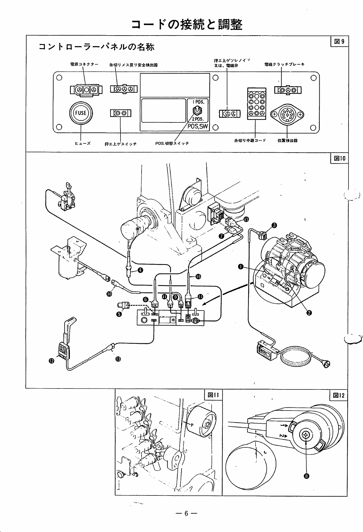
r/i"
• - K
wu
/w ^
±yw±uuX'^^k
h
a--7-<7)P0S.X-f
*b'yhL'Tia^'^'C
^$^¥11(1119-12)
1.^
—0©$:=J
—
"7—I
2.'n£Tl5iX^
tSo
ti'o
—
5/Ei®X^
Y^<^)zi
-y
^ zi y Y —
I
xylltiJl^^LiAtfo
1. t h W ^ :3
l/M
LL
/u"C<
L
^-e</;:'$
'y^(±.
^
'•2P0Sj{c
2.
=
-1^^
L r V^^ ^ t ^ fit
3. =
x>^«4'{c.
(±,
7V
—')
4.{|iW^SX>cl^{c7'i
^to
{|»M^os:fc(±,
l^li.
s^?.
m?)Jii$:-9Jo/::'). o/"c<h ^
t-±A.<^X'Z'BLM<
/j^Ao
5.mmmn^rx^-xymifzyii)j^.
^
—(C^Lii
> h ^
i^-(7y%J±^<m\\^tinmir6zt^'^n
X;^
—(±,
fjL'ffl
L^-<'^'C'<
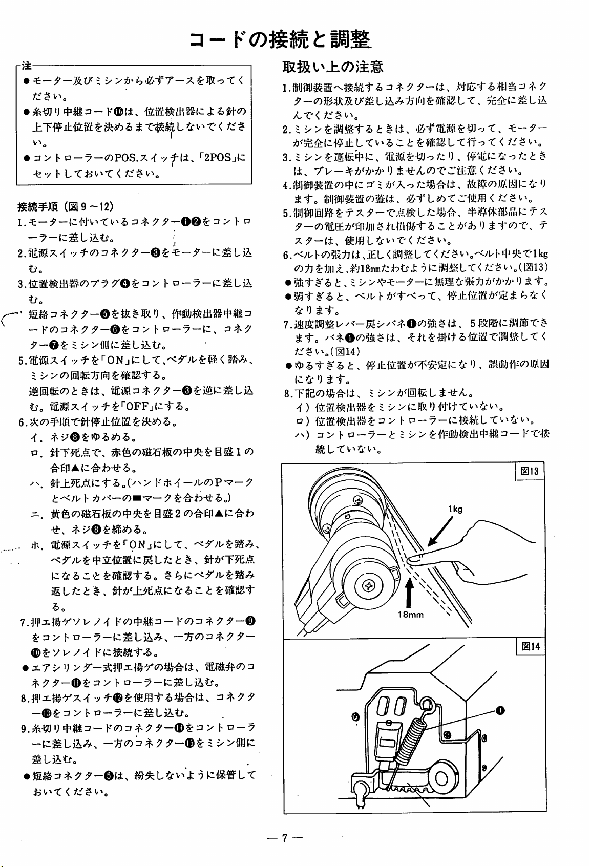
6.-<>'Uh<7)3g:tj(±,iEL < v^'<>'H^fh5li-C'lkg
X)
:l7^iJ
nx 18
mmb
O J;•)(C
X.
5c^uIILiA
L T^fo-r</i^ V^
¥?fi^i>iv}i^iSiiva^TX
ttcox\
L-C</.; $ VX„
• ililil-#'^t.a
•
?3^i"#'<i>
4-0
7.
tto
A:'^v>„(1114)
•
{-4
i h
^to
u-^<—
/<^xOc7)5iii$(i.
#±iim7!>^'¥^5£{3
0 ^ 1"o
T.
^<^x0(7)?jl5
^ {±, 5 {-
^ti^m'^hm^x'm^.Lxi
4
0.
;f>
y
r
(II13)
tto
»o^-<
tiii
X'^
')
tSo
6.
^k<n^mx%mi!LMm
-i.
^Yi\lAiz^b-±^o
^^.
i^•±MAiztho{^^>
t^ji'
•^i"x
Ti-x.
€7l^>x>f
•
jlTxU
y 7 y h o
F 7!7-'<—CO"*^— ^
>';^^-^^Tx•^ir^7)^#'^(±,
•yf-^^fOFFjCt'&o
Y7t-^^-}V<7^V'^-9
ho
•yf-^rrpNjtcLT.
—7—
^"ab^ho)
M#c7)3
-f)
D)
/n)
IkLT^^4v^o
h
D-7
S
x>(cIrxO'^t{t-t^^4v^„
I-l^-7-(-^^^ML-Cv^4v^
—^ i
/
®
18mm
KT'I^^
HIH
—®$:
9.:^-^
-{c^LjX;^.
ULiitfo
ij
u > h
a---7—Ic^Liitfo
Korr^xy
> h D
S
xvtJtc
—7
— 7 —
Page 10
• i
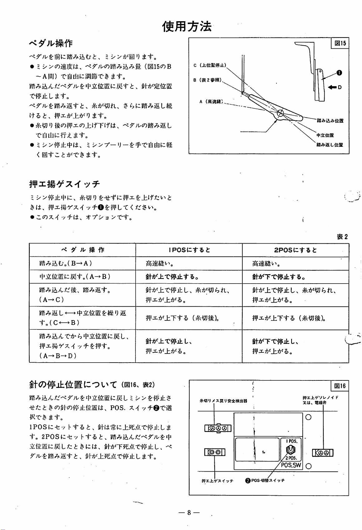
X>c7)ii;^(i.
-Aiaj)
-C'lEiEl:l{^»-C#^1-o
(I2115c7)B
c
(±<4afi9.it)
B
(a2
T'^ihL^to
• ')
=
#(i.
•
t^c7)#ji<7)±{fT(f(i>
<
HH"::
i-v(9jttc,
a:;&^"C# ^
}i|ii}Srx'f
Z<nxy(
y^li^
^ ^ flF
l^1'?^iAti'o(B->A)
t3m-^{cj^t„(A->B)
?b(c!?'§AiRL^L
^1-„
i"o
5-tt-ttcWiiS-±lffcv^i
•y^OS-}i|iL-C</^5v>o
+7"i-3>f1"„
iposcts
A
(iBi»«
a:
+2inaa
2P0Stctsa:
ttA^'Tt'^lSjhtSo
{A->C)
L ^ ') m.
to(C<-^B)
#i|lirx^
(A->B->D)
jt-feHlCOl^T
-yr/ja:
KT'#
IPOSC-bv
to
r;u^ifi^<^;fita:,
^ 1"„
2P0S{c-t-x
-y
t$:Wt„
Yt^t.
m'm-C±?E.^,ri2;?jl:L^
ht-2>a:.
m'±^z.^.X'W±Ltlro
POS.
(016^
X^vf-0-Cii
|llli7!?>'±A<^o
tfI'X7&<±Tt^
itA^'JiT^|!jhLs
«2)
m'±X'W±t.
W:sL^<±^<ho
iWTTi^±Ls
POS.SW
jZ.li.
L
@16
is^#
e pos<a®>i-f
— 8 —
Page 11
017
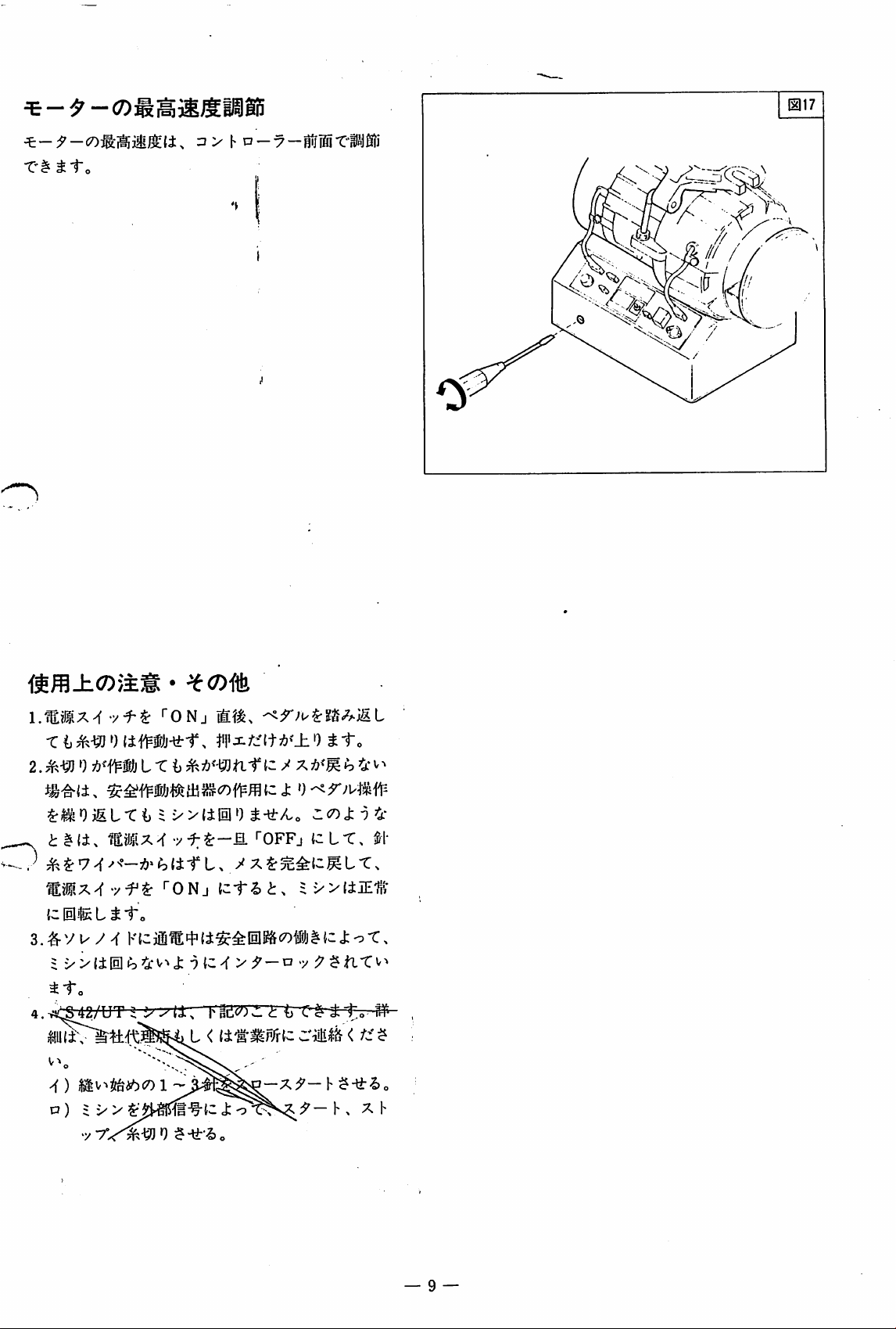
*C^^1"o
:3 > h a
—-7—
f"0Nj
0umj-^t.
2. 0 ^ b 4- V^
=
xXiPO
'tgn^^
""ONj
{cEliigLii-o
S.^Vu
4.v^^/Ur
|!UL
y ^
K{cjffi^4'(i^^0g&c7)f()j^{c
tto
^^^
U.
>() 1 h
D)
5 X > J: ^ — Vs X h
^-lirAo
^OFFj
{c1-|)
|'pi!</0^<L
<
(i's-^Rlrlc
^<^Xl^<s:
tcLT,
axXiMi-
{j
r^|&
tto
M-
j:o-C.
<
^-lir^o
•y7V^0
— 9 —
Page 12
y
^(Dm
r}±
•
3.-K^f1-:T-nKi!l.'.'f-C'^-&J:•?(C,;f>
:
'Mx>f
u/n'—0A»i^{±-f
•y^$:'"ONj{c
LTia
:^®liSJi (018-20)
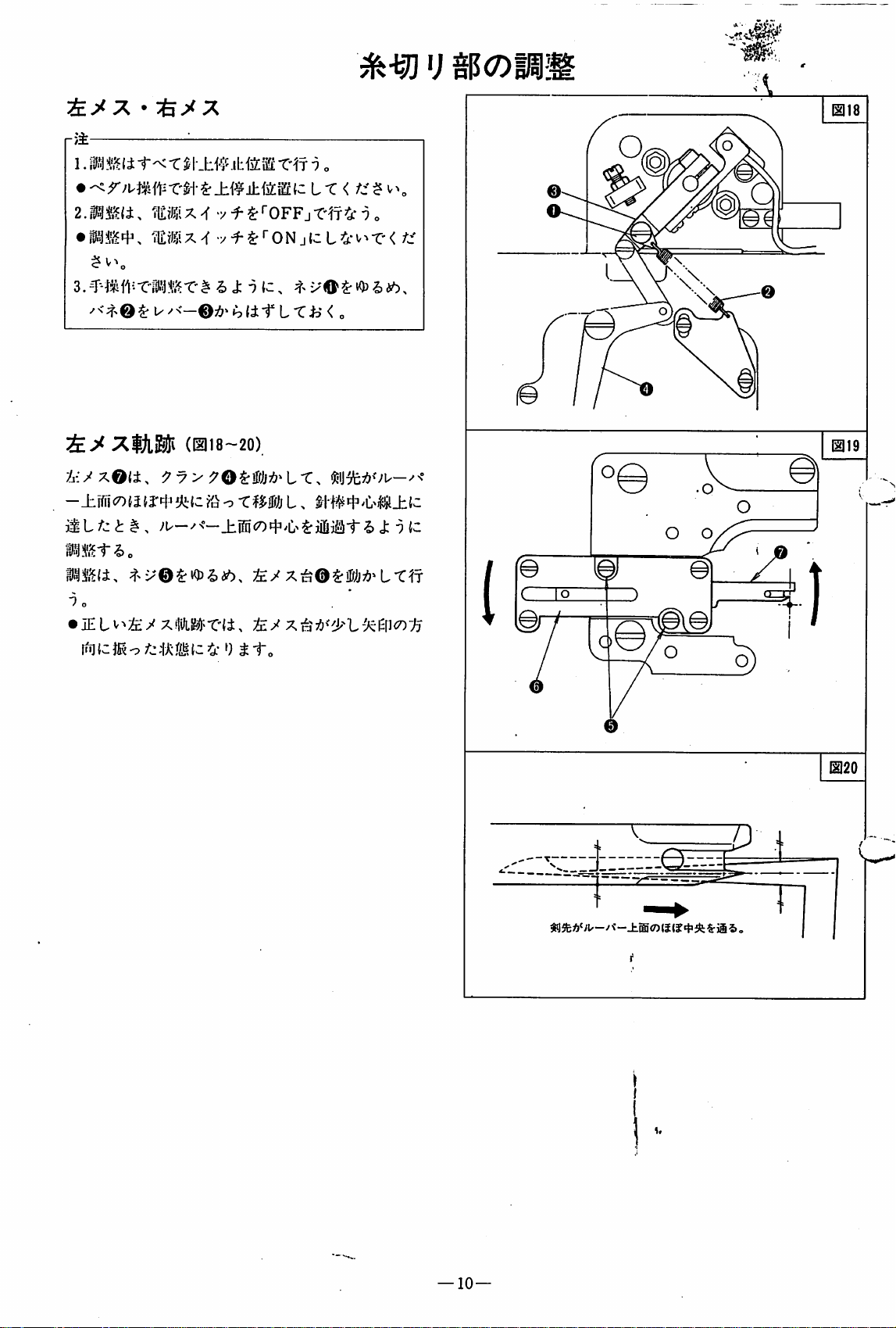
y_i:yx©(i.
Bnm.
"? o
•
JELv^^y
^y>^O^Wj^^LX.
-'u—cfc
xWTii^
:fe/
L^*v^-c<
< o
xi^j75<i:i'^L->cEn<7)">/j
/jf
"3(c
SPjft
—
10—
/"t-Ji®<7)(i{?«P»
^ii
5>
Page 13
h
p—
^
a
.SimCO
m^lts
•
^-'JOi:^h6bs—BLx-v7
•
U^<—Qtyy'7"/
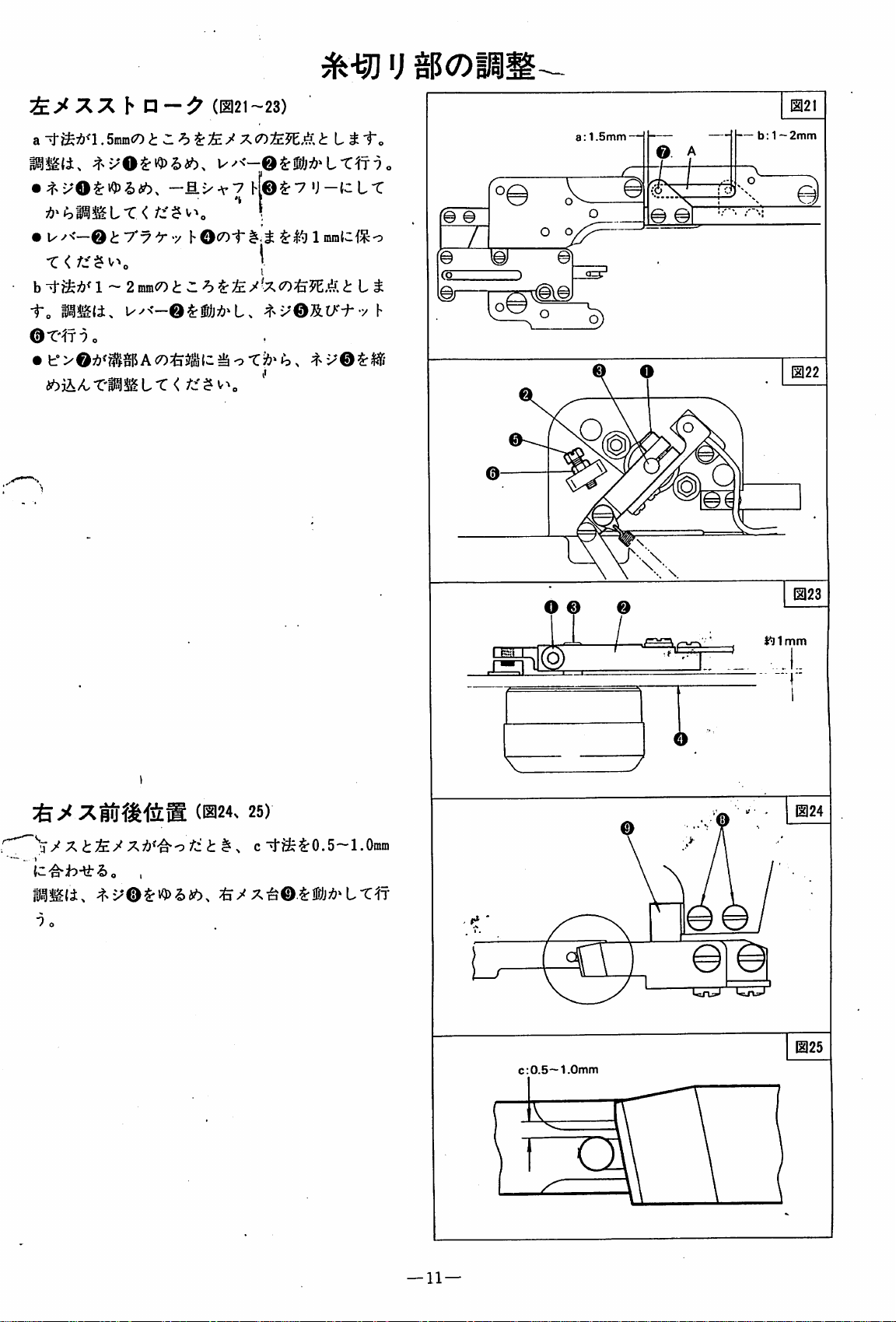
(021-23)
7s<r>tEM.^s
W^<-©^i/j:<>^Lr^T9c
tLtto
h,©^7'J—{cLT
1 inralcj^o
© 0
zz.
O o
a:
1.5mm-
o
iC
© A
fe(
© 0
—b:1
O
1121
~2mm
b
i'o
PiUli.
©T'It^o
1-2
mm<7)
^^
tLt
-t-x©5.t/-^-y
(s:
ler
h
o\
mi
a=r'
1123
O 0 ©
-'y'
xafrfi'feg
(024>
~\y'X^;£/X7'/'^o;^i<i:
1 o
25)
c
"vj-^i^:0.5-1.Omm
Ts-^O.^Wj^'LX^j
0.5~
c:
V
^ \
1124
^
1125
1.0mm
l\
—11—
Page 14

0.5mnn
^<h'r^^\zlEy»)
"^7
7M&±Wi::&:&7
>feV
X^j<lEVtA<r> ^ / X^jlr^}
(c
-2,
j: ^ 6 o
m%m.
X(D}^i^
<!:
^ 'J lif t
^ ^ ^0.5mra{C'^i^i"o 31, ^ /
A
?^[S
i B
UlUc
Injii,^
{c^^i-
{c »
cot
X(0
/ X ^
^ ,
JU-^LX\
&t^&th\
•^\
c7)iiz0j^jitiiLiiS
b-^J-ac^^^^.O.SramfC'g'h-yr-t
(i.
'^y
^<t-'I±::/joj!l.l^'^f(±,^^xO$rllltt:^To-t
^{cHlti,
pjzlait
l£yx^^
^<nmu^h7£yxm^.<mii>xi^z'Mti^mm
LX<
ffo'C<
t.
^<^^}±^<^A\<=a-
^T%^^
tto
01to
X
X ^<7£^z,'}f.<n t
<
<
i.
a
:0.5mm
b
:0.5mm
12-
Page 15

rii-
^30
itit-iaSSrL-Cv^Jto
r>±
'•
tfett"5)L.
!
1-.
Ic
-fe"yhi"^ o
-t?-
i
(B
u
[1132
yu/^Ku^^-
a^?£$:8.5mmlC,
0
~o.3mintc:^^j:9yyy^
'ho
^^'JO^^hibXXrio
±^ik-(n
$lil©<7)tljft h ^ 2 mrat^I'^bi"<>
0(7ym"ik<r>mn,^ <
ti^0i:^hibXXfi
if±MAX\
;^^A>f©<7)7fe^®7&^
±^©^7'y'^-•y
Ky^^—©^r-t
to
o
0^t)12.5minaJ^ J:
htO-f ^
y
7(-a
i-t
f]
o
.
0-
0~0.3mm
-0
0
mmtho
ti^0^^hib.
Xyx>/
\'0^W}^'LX
^T 7 o
— —
12.5mm
V"»o
—
13—
Page 16

C. ^
-^J-^ ^ L
i} 9 > :^;<50^^'^, a =^:-j30mra • b
mm
• d =^^16mra • e =jf:'l 0 ~ 1 mm(C'^i9-tf"'C <
|2134<7)
a • b♦c • d • e <50#
It
=|^13mni
to
• c
=15
©
^ n ^ ^
ij
9>4<Km}<^t
^ m
1.-H^.>'Mihm9yy
mS4<r>t1iZ^oSmmiZ^h-^X
I X
X <
2. ^r>^jO_hi®56> io ^
-c</;:$v^
e 0 ~ 1 mm(3'^i9-ti''C> a
TIto-C
c '
d(^^-mi:'^h-\tX
<
@^»c.
9cr)t'>0^'io.
9yy
mmt.
' O •
^^i^ib^^M^xXr-oXits
^;coMf({ciSL/::-^-&{c,
(b^^MibX^n^X
wm
0
t).
<
x©$r5ifea6t:^f
-C'l^3lOmra{C>^;b-y:
<
t h .
W.<L-C
^f^<^lil^tT^
<
<
o
b •
f
-14-
Page 17

use
r}±
^0.5min(C>^h-l^Ti>
r)±
EHt;^^-
•
<o
mmmu
A.EHrKO^:
;5'-0^EHtX;J'-O3
tho
2.AC100V<7)M»(cE
ULiA^.
(«#-t#73500l!-lOOVffl)
(M#-t#742095)'(i.
HtX:5'—9'0^
X^
•yf-0^fONj{c1-|,„
0 aoms,: ^
<o 1
-yta.
1
""pPFj
S
x>11^0=?
h©<50l-
SU^T'to
CtriJ
Rt/
0.5mm
0
f
/
-/=i^
[i37
AC100V
L ui:^
y > L T iD 0 . y u />fK u-
DM^
y > L T ^ v>
•wmTjsy y y\0-/}^.^M K
(•7;7';f>.y
iwm^^yyyo^<.^Mthmmx\
{C-b-yhi"
i.yy
y ^ Vu
mfTs y y
"2)
h©)
I
o
h-f:^'l>z^t'W)^-^fzf:fl.fX\
ro^'m
Z3^
—
15—
Page 18

—
t-ct
51
•/i
K { 6
MmiO#)!?,)
Rl/oy
m?D?:x^
r
"riD^^i"o
^ ^ ^*0.5rain{C'i^;b-li'Ti> < o
1.Wij#ittl4^$lii:3—
bto
Y
u-y-{z^l^tfztt.
v^^rONjtcLTHfnl^.^L^i-o
BCSVmfz^Mti^
K(7)=7;f.
rJ'
—-y
J; 1
2. T X h /<-(7)0jlllj^ Ijim=J— KCOrh
fllll
rXrJ'-li.OV^^LTiiO.
©
(-7
r 4"-y h©)^ b T ^ >C
5V(c=S.--g>o
^ "i'o
Vwy-fKw-^^-
lEclj
$ -It /-j
$
x>
hL
hO^oi"
rO^T
^^-(7)igjjl{C, 0
/-c'{tT\
© ©
0.5mm /
Ezn^
•fx^-:f}<5Vi:mn<LX^^6o
- ©
(-^r?>
•y h©)^ :^^4- ^^
3.il:4'^x©^iQ)'i)i?^,
•y
h©<7)r|>.i:.{C'^h-y:-7,„
T X ;7
i~ ^ o
4.
rX;J'-^<5
-/)>
0V ^ ^<i-irifiIS|T\ffiTi/j^^a'.^©^
4-^
••/YO^rhX-eilVjinfcT'^
vuy
>f
VU^--7,^
ifdj^-t^:
V^ , 5V
'fl^iffij'l^th^©(7)If>l!i^^^7'f.
6 /Ii'ltiiii < {c-fe y h
^
—
16—
Page 19

^ m
>f)
;fe/x^
V
x;&>'^t^{cT
M
it
^ ^ X ^
^L
h o
pmtiM
10~12M
IIH
m
±
tc
•bT)
tl
tj:
a)
;feryx3gto^':fe/x
O "C ^ O
ffl
2.;£y'
3.;^.-^
X;{?>';^x$:
Oil#. ^7!?^^-^{3lQ)|>^-C'V^
9 t <
tux
ho
x-^mw
L r
X^j!£-r^<Olz-t-y
^XCO'X'A.-/)^
lU±;£{ctU'i)J;9{c.
^•\tho
•
;fe/xxFD
;£
y XililLg^xT)#®!!!^ ^ 1" ^ o
— x>jiUU t L T <
x±Mi:
h
i^m.^
^ i t h
IX
Vtho
^ 1mm
•4^/7.^j'£{z
f -y ^ 'J
lOM
12H
12i'i
\m
12M
lOM
14K
X
1!)
4^
4.^y'Xc7)7r:^„
^ -y ^ t^'-o X
5.
Xi^itlX^^^j:^^
>f)
a)
1.;^.-^
t<^mi
d)
2.
3 > h D
—-7
—
;&y'X$r{lliE(J® < )1"'i)7!?\ Wraut
^^tho
^ t ^ 9 — L
mmu^^mxi±.
3 > h o
—-7
—
j^tfo
rrr??.txmt
h,
4
M.
7M
6 ~ 7 M
7M
—
17—
Page 20

/^
HI
(«iiS:^>4)
M ^
mmthM
m
UN
U 1
U
isb 1
tC
JU h
1 ^
tt
1 ^
iliiUT
t^
" S
(± a °
L'^
nbxf
•b}]
1.^^
2.>fj^
3.
4.T^^I'l'J^:^?^'IELvMlA{a:(c-fe-/ h ^
2. u ^ ^ ^ co^< ^^0
X^<^-C7)y<;f>Hl7:j<5jfiV»„
T
t7)
KJ)^LffI;
;l'L-Cv^4'V^o
l> L T
?!;<TJEii
L t ^^1) 0
-g)
0
;&y
V
x/<^^^iELv^iiic{c-b.y
'''^•t-^l±$:3i}{
T:^;<7)»^
i"'5
-2)
i?i>ifl;t:< 1"-&0
T^.1>I'^^IEL<
Or
ho
„
-t-y
i
ht^o
'irho
h L
12M
12K
14M
13H
14M
1
17M
'
12H
H
W 2
ts 2
13
tV
^
J:.
b
S
m m
m
m K
^ b
4^
7.
iV
0
^ (7>
v.^
Si
7&^'
o
3.j:.T-)±7:>^'^iiLLTv^^„
4.
'I'lLfll^^f-
5.1'l'i|v)rt
2.Vu/-(
3.71^/^
<7)
i(i „
u > h n
Vm)]UXUM^H^o
Ki
=»>
h 0 — 7 —
—7—^<7)1^^
^(7)
^•^i^^Wiib^iDiro
mizvt-ox.
^T—^Mho
mm-fho
sLr~-}±{Y-i^f±)^
{C-^:b-lf"'5>o
lEK^f^-tho
LLlt'^i^o'Cx
yu-y-f
Ellllc^'^^o
lEK^mtho
i ~
1
Skg/citf
17M
5K
5K
6~7K
17M
6~7H
1
1. rj > h D
2.
y u / ^ K
—7—(7)7f:^„
r? > h D
y
u-yy
—7—^:^1^'
-ho
1.
S
1. ^
t>
<7)hIC'Ii^^J^o
^iEL<-t-y
hi
'ho
^ 4
^A °
y 1/ y ^ K
yu-yy
18—
3.
13M
Page 21

ItL<(±x
111 7 i ;u
y-0}a»
yi>i9 - o
^AiSST'illfiLJ-»•
9-fi>•y(;>««r
i . -t- h
A'??
U<W<
•ft4/jrfin
/)'h>)t-to I
1 - 2
</:So„
7 1 n,
JRj'l-tf
yfli:1ffi7
9-It,
J-Co
< n
9-<nmf!^iUr
P9
9(0(2)fli;Sr:fft!ii:.j|<ii
i
(3)
7 ^
9-f
7'Srft|$^S-tt4/-»b!|s«pU
9 -f i V
T'UWmtOtt^lJWSrlfltt
S
l»o
i/i.
7 9
7-f-•7-U-#;i.f,qai3f;4f-Ci
A -
X-Cft
V'Attfi-1
</iS
l»o
ft
C/»fliSlll(Sni«01
L ft
1>T</icf
ftCf.
mSEHTiftcSfe^liJMwWteSrfrftiK
as u rA*^ ffiffl u
/MA'7-(iVri;j;<
B.
'e-h»Hirx!l27)J;AU»WL
SOo
WWHlitfiA-tUfjJffl
i»o
u r </is
t-ciaiffi
iftiauft
•
L T <
rfififll
v».
t
T <
i/i
l|iT
1
i-r.
(21 7 9 /
(. JKO/N'JU h
'{'7
7 V L
U
77
X7
9.\-sni!i=i'-yOi:,
'
i
101
/i
TO-r.
•V7-(150*)
h-C4.
[0.
STfttfi.
.-l-.
LS-J»R!v'T
fc]. y ^
(±«:i»/;!fc(SA«i»i(»ir'WsiK'vr
S
01.
8<rmill^i4\ir<
d).
mft:«5:ftl+Ti»fti»t-A-
- V
tl
IIIA'
z<n{ii.^ii'h,
K L./-iicffl(-.iW«5i'
797-f-7'77-7
i -
n,,
h
Oo
-f - >
T'fiSliaS/n/MSr'I'fiA-
7'ifSi:«ii<
liPL-7iir
PT*«.<
/:fl.Jli;Jc(nJ;••,
T <
-r-1}-9A'f
ifis#StAj(«llcf-
B.5f3t:Ayif>ii-i07.-f
O 4- -U -V
h.
il'7'9
X y V
</iJf
i»„
/iSi'c
-V/7)7-(
<
77.(
cf-tlS
< /•
x-
0).
li^.'I*.
L ffi-iyrt
<
^fliffliiw
> fR •. r
(h). 7 V •/ L S:
W is JR 0 . m (liM S:M trs L r < /_' &i >,.
l.l I- -0 - I- lu
li|.
IJcj.
frai
.y.-CX ,
lOOInKJ.
#9 il; Sr < •)iSL
A,.
rWiJIK
Tin
Ai^Ko
b L d- L
ajfti?MA'JJ-Cy4i»±M«A'.Hj<
h
A.A'iftillLfti,»l«ll-A'./,
0 i -Co
4 C i
10jS«Afft-t-
SrffiiS
t, T <
A-iFi'o
I-
/uA'lOlte
-f-j.-7-U(i|^4l!g5>7)tfS/1ifl1A'A7T
l»4To
4
faffP<AiSt'.
•
A:«
ft
C
(41
nrWllieoiiflft
7 7 7 -f- 7 .f V r A'MI
A'.® < ft o A: n
A'«<];
L J
-CtOT'-'Afeli^WlSSrA-WJ:
(;5:}ftt.T<
eaiizoj:
S:>P-Cfc57!lti|S7)oi»A:
A'HM
X7K»'<-
AiSi'o
ai;77
i -Co
/
«-KV7777
fc^«7)-C
v-cr^T
77-ffls-f-il'
t
Iti-
4 fc1?
n 4
»«flf
"i
/
cwd-M
X
9^
, +
-ryX
, h
m'i>*
7
SA
/*7y>7
;»:(;
7 7 •>'>
"fUltSSr'lli'tfcS,
t -Co
aiAfft
S
l»o
n«M
t"///?-
l/rLiWWWfc'JlflftL
9^y
-f-ffiPttfrSatS L T < Ai
7777-M
A I
fryK
7777797Vf
(DntiSi^ryj'J.
.
(2)i!li)fi:Stlt««'"'-J:
(3ma»'Hli3lcoikX<ny^'9
t-h
{4)4 UftW>4 y)(!iiifllUSa ft H L i -C.
ism
L t 'isiifflijsffi ft
(6)lttj8iftA/L.
{6y<rt\^M
:^T7>(Sftgftia*2L4-C.
>-»«6c;og(fe
0.
0.
7'i/>
hiS«iA'(;,'<r/Hi:'''CBISt7-'/>
ftlfi«[LTK4
0.
'<r.'H::'-^BBftl&!fl»'«imuttl}iiLTK4
laUftHLT.
0.
rrL«."<#'/i'-b>-V-f[|SftJR')
AifcA41-.
4_r
>wftWtil;?-«-i-C.
OifilftliiftHLl-C.
9 i ')
t"-?
7-ftHL4-C.
.hae«oifi>7)ii«fiT-aiAii;v
')a<«rMiftnL
7
Pa^-^^-fttA^
-<y^^i'-fei'-»CR»ftlBc')mL4-t-.
4i-.
4-C.
>1.L/.;iS»7)(«iJt-T-ai
4 -•)-,
hffitti
5 4:7>
Page 22

INTRODUCTION
This
manual
Mechanism
Forother
contains
usedonthe
instructions,
the
refer
opeialing
WS42/UT
to the
and
se-
machine.
WS42
vicing
instructionsofthe
instruction
manual
Thread
(Cat.No.8115).
Trimming
GENERAL
The
WS42/UT
motor.
trimming, thread wiping and foot lifting.
Pressing
under
Then
lifts.
The
the
the
needle plate.
the
wiper
The
presser
TABLE
COMPONENTS
IDENTIRCATION
WIRINGOFMOTOR
SETTING
INSTALLATION POSITIONS OF MOTOR AND
POWER SWITCH 23
SYNCHRONIZER 24
MOTOR
SOLENOID
AIR CYLINDER OPERATED
CORD CONNECTION AND ADJUSTMENTS
CAUTION
OPERATION
CAUTION
ADJUSTMENTS ON THREAD TRIMMING MECHANISM
LEFT
LEFT
LEFT
RIGHT
RIGHT
RIGHT
RIGHT
SOLENOID
ADJUSTMENTS
LOOPER
LOOPER
THREAD
THREAD
ADJUSTMENTS
ADJUSTMENTS
ADJUSTMENTS
TROUBLE
MAINTENANCE
PITMAN
OPERATED
KNIFE/RIGHT
KNIFE
KNIFE
KNIFE
KNIFE
AND
KNIFE
LEVER
THREAD
THREAD
WIPER
RELEASER
SHOOTING
DESCRIPTION
machineisdrivenbyan
microprocessor-based
pedal
backward
takes
out
foot
OF
CONTENTS
AND
MOTOR
FOR
ROD 24
KNIFE
MOTION
STROKE
POSITION
HEIGHT
LEFT
KNIFE
SPRING
SPRING
ON
THREAD
TAKEUP
RETAINER
FOR
SAFETY
WITH
WITH
AND
INSPECTION
at the end of
the
needle
canbemovedupor
220/380V
FOOT
AND BRUSHING
EH
ORDINARY
LIFTER
FOOT
"Back
and
ALIGNMENT
HANDLING
DETECTOR
TESTER
electromagnetic
precision
sewing
threads
downbypedal
LIFTER
controller
causesthe
from
the
FOOT
clutch
controls
presser
LIFTER 23
type
needle
looper
foot,
thread
and the
actionatthe
needle
positioning,
startof
~
forth" 31
MOTION
'• 32
PARTS
TESTER
OF
MOTOR
positioning
thread
to becut off
presser
foot
sevying.
PAGE
22
22
22
23-25
24
25
26-27
27
28
29
30-32
30
30
31
32
32
32
33-34
33
33
33
34
35-36
35
36
37-38
39
—21—
Page 23

COMPONENTS AND MOTOR
The
WS42/UT
and
WS42 machine equipped with
mechanism.
The
standard
suitable for
useaslistedinTable
machine consists of a foot lifter, motor
the
thread trimming
motorisPANA-STOP
the
voltage
and
1.
phase
E.
Various
are
provided for
motors
VOLTAGE
lOOV
200V
220/380V
415
V
220V
PHASE
1
3
3
3
I
PART
802009
802010
802011
802012
802013
NO.
PANASTOP E
EPSIG-MT
EPS3G-MT
EPS3G-MT 22P/380V
EPS3G-MT
EPSIG-MT
TYPE
lOOV
200V
415V
220V
Table
1
NO.
IDENTIFICATION
The
machine is shown by
and
the
UT
a slash
device
/.
Example : WS42-01x356/UT3.
UT
type
DEVICE
UT2
the
machine type, gauge
number.
Between
ORGANIZATION
UTS
Machine incorporating
PanastopEmotor
Solenoid
operated
foot
lifter
them
PLEASE
When
with
is
UTS
the
thread
Air-cylinder
operated
foot
lifter
NOTE:
using motors
the
sequence
CHART
trimming
Motors
Solenoid
operated
foot
other
chart
UT4
mechanism
other
lifter
than
Panastop
separately
than
Panastop
Air-cylinder
operated
foot
E, please proceed
available.
UT6
E
lifter
WIRING
FOR
When
For a 220V power supply, open Cover O and re
wireasshown.
shipped, this motor is wired for 380V.
OF
THE
220/380V(Part
MOTOR
N0.802011)
WIRING
FOR
220V
Green
i
BLACK
(for
—22—
LAMP)
12V
20W
WIRING FOR
(when
shipped)
BLACK
(for LAMP)
380V
12V
Green
20W
Page 24

SETTING
INSTALLATION
FOOT
LIFTER
POSITIONS
OF
MOTOR
AND
Refer to Fig. 1 and the supplied WS series pattern
paper,
correct
POWER
Install
and
install
positions.
SWITCH
the
power
the
motor
and
switchonthe
foot
lifterintheir
machine table in a
suitable position. Staple the motor cord so as to
keepitclearofthe
belt.
-rf-
WS42-01~07/UT
-159-
1
"TT
1
Motor
fixing
hole
3-09
Air-cylinder-
fixing
hole
o
o
G
Foot
solenoid
fixing
Flg.l
lifter
hole
225
WS42-30~33B/UT
3-09
Motor
fixing
-159-
-225-
Air
cylinder
fixing
hole
hole
92
-130
^ "
-140-
(k-
\
020
Synchronizer
lead
cord
inserting
hole
c
O
o
O
—
23-
Page 25

SETTING
SYNCHRONIZER
Put
on the drive belt. Refer to Fig. 2, and
parts O —
®.
• Synchronizer O and Adaptor O should be fixed
firmly.
• Staple the lead cord of Synchronizer O onto the
table to
keep
it free from
the
drive belt.
attach
MOTOR
Refer to Fig. 3, and install
•
Set
SOLENOID
Refer to Figs. 1 and 4, and install parts ® to
Connect
with
PITMAN
the
Solenoid
Pitman
speed
regulating lever
OPERATED
Rod
ROD
the
FOOT
Lever(Dand
®.
motor pitman rod
and
rodatSO'QO".
LIFTER
Foot
Lift
Lever
®.
• Loosen Nut and adjust the stroke S. Setting
distance "a" to 25mm provides standard stroke.
•
Adjust
has
Pitman
a little play.
Rod ® so
that
Foot Lift
Lever
®.
®
dD
T
—24—
a
:25mm
Page 26

SETTING
IAIR CYLINDER
OPERATED
FOOT
LIFTER
Refer to Figs. 1 and 6, and install parts O to
Connect Air Cylinder ©
with
the
•
Adjust
has
TUBE
supplied
Pitman
a little play.
CONNECTION
Pitman
Rod © so
Refer to Figs. 6 and 7, connect
and
Foot Lift Lever ©
Rod
0.
that
AND
ADJUSTMENTS
Tubes
Foot Lift
correctly.
0.
Lever
©
m
LUBRICATION
Remove
here
•
ADJUSTMENTS
1.
Screw
into
The
oilshould drop from Pipe ® as one drop per
ten actions of Air Cylinder
Turn
Screw © and adjust this.
Regulate
©.
Lubricator
the
air
Pour
fresh
(D until it
pressure
®.
from
turbine
reaches
the
oil # 90
air
from
line A.
compresser
to 5kg/cm!
2. Loosen Nut (D, turn Handle © and regulate the
air pressure to 4-5kg/cm?
EXHAUSTING
Air
Filter
accumulates
DRAIN
the
drain.
Exhaust
the
drain
by pressing Valve ® up.
• If
the
accumulated
drain
exceeds
Buffer©and
enters into Air Cylinder©,the accident may be
caused.
ADJUSTING
SPEED
CONTROLLER
Adjust Speed Controller © so that the presser foot
is
lowered
smoothly.
25
Page 27

CORD CONNECTION AND ADJUSTMENTS
CONTROLLER
Power
source
connector connector
PANEL
Safety
detector
Foot
connector
lifter
Electro-magnetic
clutch
brake
Fig.9
® o ®
Fuse
Presser
lifter
®®®
g®
connector
foot
PCS.
switch
7
changeover
1
POS.
0
/^s.
o
o
Thread
trimming Synchronizer
junction
cord
connector
o
o
Fig.10
—
26
Page 28

CORD
CONNECTION
AND
ADJUSTMENTS
-NOTE:
Be
sure
to
motor
extend
and
machine to a good ground.
earth
(ground) wire from tlie
Donot connect Thread Trimming Junction Cord ®
until
the
highest/lowest needle stop positions have
been
setbythe
Set
the
POS
CONNECTING
1.
Insert
the
controller.
2.
Insert
Power
synchronizer.
switch
on
STEPS
Conneciiors O
Switch
the
controller
(Fig.
and
o
Connector
9-12)
of
© into
the
to
"2P0S".
motor
the
motor.
3. Insert Synchronizer Connector O into the cont
roller.
4. Pull
5.
Safety
the
controller,
Turn
and
check
If
the
out
Short
Circuit
Connector
©.
and
Detector Junction Cord Connector © into
and
the
power
machine
Connector © into
switch
the
directionofrotationofthe
on.
Press
runsinreverse,
the
the
pedal
re-insert
machine.
machine.
insert
a little
Power
Connector ® upside down.
Turn
the
6.Toset
1)Loosen
2)
With
the
mark
power
the
the
centerofthe
of
switch
needle
Screw
the
stop
©.
needleinits
scale
red
1.
off.
position.
lowest
magnetic
position, line up
platetothe
3)Bring the needle to its highest position. (To
do this, line up mark P on
the
line,on
4)Line up the
with
Screw
5)
Turn
the
belt guard.)
center
the
•
mark
®.
the
power switch on,
of the yellow magnetic plate
on
the
the
handwheel with
scale
2.
and
press down
Tighten
pedal.
Then
check
that
the
needle
stopsatits
lowest
position by returning the pedal to the neutral
position.
Further
est
7.
Insert
Cord
Insert
•
When
insert
controller.
8. When using Presser Foot Lift Switch
Connector®into
9.
Insert
tion
nector
check
that
the
position by pressing
Connector
into
the
the
using
Solenoid
other
© of
controller.
Connector
the
air cylinder operated foot lifter,
Valve
the
Connector<Dof
cord
into
the
controller
© into
the
machine.
needle
the
pedal backward.
Presser
(B)
into
Connector
controller.
the
thread
and
stops
Foot
trimming
the
at its high
Lift
the
solenoid.
© into
®,
other
Junction
Insert
into
•
the
the
junc
Con
CAUTION:
1.
Connect
inserting direction of
2.
When
off
3.
Note
is
switched
the
Dustinthe
4.
So
5. Do not use
try
of
6.
Keep
1-kg
tion of
•
Excessive
and
•
Insufficient
and
7.
The
canbeadjusted
Adjust
(Fig. 14).
• Insufficient
stopatdifferent positions
8.
The
1)
The
The
2)
3)
The
by
cords correctly,
adjusting
and
that
the
motor
the
off
the
does
machine
while
eventofpower
controller
alwaysbesuretoshut
any
testertocheck
because
the
the
forceonthe
motor.
the
the
tester
semiconductors.
belt tension correct.
centerofthe
about
18mm
belt
tension
belt
tension
needle
may
tension of Speed Regulating Lever Spring O
to 5 positions.
the
tension by changing
spring
machine
machineisnot
synchronizer is
controller
the
safety
will
and
detector
tension
not
making
the
mating
machine, be
not
rotate.
cannotbebrakedifthe
the
machine
sure
connectors.
sure
is running, or in
failure.
may
cause
it to malfunction.
the
controller
the
controller circui
voltage
may
damage
Adjust
belt
allows a
(Fig. 13).
may
overload
may
cause
the
not
stop
correctly.
the
hooking position
may
cause
and
result in malfunction.
run in
the
following cases.
equipped
not
the
with
the
connectedtothe
machine
arc
junction cord.
/
18mm
shape
the
cover.
it so
the
belt
the
and
power
power
some
that
deflec
machine
to slip,
needle
synchronizer.
controller.
not
connected
is
a
to
00
—27—
Page 29

OPERATION
PEDAL
Press
•
Machine
B-A.
Return
needle
backward
pedal
•
• While
1
PRESSER
The
ACTION
the
After
foot
be
turned
pressed
can
pedal forward
speed
can
the
pedal to
stopsatthe
and
the
and
the
thread
be lifted up or down by pedal action.
the
machine
freely by hand.
FOOT
and
be controlled
the
neutral position
preset
position.
thread
the
presser
has
been
is stopped,
LIFT
SWITCH
the
machine runs.
between
Press
is trimmed.
foot lifts up.
trimmed,,
the
handwheel
distance
and
the
Keep
the
presser
presser foot lift switch O is available as option
pedal
to lift the presser foot up without trimming the
thread
while
PEDAL
the
machine is stopped.
ACTION
IPGS
the
the
can
C
(needle
B
(needle
or
as
A
(sewing)
SETTING
DOWN
preset)
UP)
UP
-
PEDAL
2P0S
SETTING
Forward
Neutral
Backward
Table
-"N
2
Press
pedal forward. (B—»A)
Return
Press
it
pedal to neutral.
pedal forward,
backward.
(A->C)
Press
pedal backward,
then
it to neutral. Repeat this.
(A-^B)
then
press
return
High-speed
Needle
Needle
stopsathighest
stops
threadistrimmed
lifts up.
Presser
(after
foot
threadistrimmed).
(C<^B)
Press
to
lift
neutral,
switch.
pedal forward,
then
press
then
presser
return
foot
it
Needle
and
presser
stops
(A->B->D)
I
NEEDLE
The
POSITIONING
needle stop position, when the machine is stop
ped by returning the pedal to the neutral position,
can be adjusted by the POS Switch
the
switchtoPOS
est
position. If
1 will
the
stop
switch is
the
set
©.
Setting
needleatits
high
to POS 2, returning
the pedal to the neutral position willstop the needle
at its lowest position and pressing the pedal back
ward will stop the needle
at
its highest position.
sewing.
at
highest
and
moves
at
up
highest
foot lifts up.
position.
position,
presser
and
position
Safety
connector
1
C®®®
foot
down
detector
High-speed
Needle
Needle
threadistrimmed
lifts up.
Presser
(after
Needle
and
presser
1
sewing.
stopsatlowest
stops
at
highest position,
and
presser
foot
moves
up
threadistrimmed).
stops
at
lowest
foot lifts up.
o
1POS.
position.
and
down
position
Foot
lifter
connector
foot
Flg.16
:®@
1
Presser
28—
foot
lift
switch
0 POS.changeover
switch
0
/2TOS.
/POS.SW
IK®®
O
Page 30

TOP
The
SPEED
top
speedofthe
OF
MOTOR
motorisadjustableasshown.
OPERATION
Fig.17
IMPORTANT
1. If
the
after
the
NOTES:
pedal is
power
pressed
backward
switchisturned
trimming mechanism does not function
the
presser
2.Ifthe
returntothe
trimming
will
work
the
pedal is
turn
thread
home
After
normally.
3.
While
the
machine
4.
The
following
1)The
slowlyatthe
2)
The
thread
•
For
foot
lifts up.
knives
the
from
position
that,
the
machine
details,
failtotrim
home
position even though
mechanism
and
pressed
actuates,
the
machine
repeatedly. If this occurs,
power switch off, remove
the
wiper,
and
the
solenoids work,
so
thatitwill
features
can
startofsewing.
machine
canbestarted,
trimmed
contact
return
then
turn
machine
are
sew
by
means
our
the
the
thread
the
will
the
the
power
can
the
safety
not
run.
also available.
first
stopped
of external signals.
distributorsorcontact
us directly.
immediately
on.
the
and
the
safety
not
run
the
knives to
switch
be
started
circuit
1 to 3
thread
and
only
do
not
thread
detector
even
needle
the
on.
locks
stitches
and
if
up
the
—29—
Page 31

THREAD TRIMMING MECHANISM ADJUSTMENTS
LEFT KNIFE/RIGHT KNIFE
-NOTE:
1. Keep the needle in its highest position for all
adjustments.
• Bring the needle to its highest position by pedal
action.
2.
Power
• Never power ON during
3. Loosen Screw O and leave Spring 0 free from
Lever © so
hand.
OFF
for
safety
during
adjustments.
adjustments.
that
parts can be moved freely by
LEFT
The
approximately
When
it should beatthe
Move
To
Holder
KNIFE
MOTION
hook point of Left Knife © should travel along
the
•
adjust
When
it
reaches
CrankOand
this, loosen
©.
the
left
knife
centerofthe
the
centerline
centerofthe
check
Screw©and
motioniscorrect,
this.
looper
of
the
looper
shift
top
needle
top
Left
Left
surface.
surface.
Holder © may be turned a little in the direction
of
the
arrow.
bar,
Knife
Knife
Fig.20
1
The
hook
point
along
the
30
—
should
centerofthe
travel
looper
approximately
top
surface.
Page 32

THREAD
I
LEFT
The
isatits left dead point.
To
The
isatits right dead point.
To
Screw©and
KNIFE
gap
"a" should be
adjust
• Loosen
start
adjustments.
•
Keepa1mm
o
gap
"b"
set
this gap, limit the stroke of Lever © by
STROKE
this, loosen
Screw
O
gap
should be
Nut
©
between
TRIMMING MECHANISM
1.5mm
ScrewOand
and
l-2mm
when
make
Shaft
Lever©and
when
the
move
© free
the
left knife
Lever
Bracket
left knife
• Touch Pin © to the right side of the groove A.
Then, shift Lever © by tightening Screw © and
adjust
this.
0.
and
(Ql
ADJUSTMENTS
Flg.21
a:
1.5mm-
© A
jZ
z
o o
O
© O
© ©
—b:l
~2mm
•
RIGHT
"Back
y
Adjust
knives
To adjust this, loosen
Knife
KNIFE
and
forth"
"c"to0.5-1.0mm
meet.
Holder
©.
POSITION
Screw
when
the
right
© and shift Right
and
left
im
c:0.5~
o © ©
Co)
1:0mm
Fig.23
1mm
'
Fig.24
©
44/
©
Uru-I
Fig.25
31
Page 33

THREAD
RIGHT KNIFE HEIGHT AND BRUSHING MOTION
The
right knife should lightly
and
slightly tilt to
makes
contact
To adjust this, loosen Screws
with
the
the
TRIMMING
brush
the
left
so
that
left
knife.
O.
left knife
only
MECHANISM
the
tip
ADJUSTMENTS
0.5mm
KNIFE
When
gap
dog
The
with
time.
ALIGNMENT
the
right knife is at
between
shouldbe0.5mm.
tip
partsAandBof
of
the
topofthe
the
right knife should
the
To adjust this, loosen Screw
RIGHT
When
gaps
To
To
Turning
to
Tighten
"a"
adjust
adjust
the
KNIFE
the
and
it to
left
SPRING
right knife isatits left
"b"
shouldbe0.5mm.
this, loosen
the
spring teasion,
the
right
increases
it.
Screw © after adjustment.
Screws©and
decreases
its
left
right knife
left
knifeatthe
0.
dead
turn
Screw
the tension
dead
and
make
O.
point,
the
the
feed
contact
same
point, both
O.
and
a:0.5mm
SOLENOID
Adjust
that
the
dead
point along
To
adjust
LEVER
the
tension of the solenoid lever spring so
SPRING
left knife returns smoothly from its right
the
right knife.
this,
loosen
Screws©and
shift
Latch
©
32
—
biO.Bmm
Page 34

THREAD
HANDLING
PARTS
ADJUSTMENTS
LOOPER
-
NOTE:
LooperThread
when
Attach
not hit Looper
•
LOOPER
-NOTE:
THREAD
TakeupO
the
threadistrimmed.
Looper
Thread
Thread
THREAD
TAKEUP
pullsout the looper thread
Takeup
Guide
RETAINER
:
0.
O so
that
it does
Looper Thread Retainer © prevents the looper
thread from slipping off the looper
thread.
i
Attach
pies
To
Looper
1/2
the looper groove.
adjust
this, loosen
Thread
Retainer ® so
Screw
O-
after
trimming
that
it occu
Fig.30
5
THREAD
SOLENOID
The
'J
is 8.5mm and
Bracket
To
THREAD
The
adjust
WIPER
LEVER
solenoid lever should be positioned so
the
0 is
clearance
gap between
0-0.3mm.
this, loosen
WIPER
"b"
BAR
should
Screw
be
O.
2mm.
Stop
Ring 0 and
Thread Wiper0 should be horizontal when passing
under
needles.
To
adjust
FINE
When
this, loosen
ADJUSTMENT
the
needle isatits highest position,
Screw
®.
Wiper © should pass the midway of the space
between
should
of
the
To
0.
• If
unplug Connector 0 (Fig. 35).
protrude
needle
adjust
Thread
the
needle
this, loosen
bar.
point
about
12.5mm
Screws0and
and
the
from
presser
the
shift
Wiper © is not necessary to be worked,
that
"a"
Thread
foot
and
centerline
Bracket
—j-
12.5mm
o
0--0.3mm
1—®
Flg.32
I
—33—
Page 35

THREAD
HANDLING
PARTS
ADJUSTMENTS
THREAD
The
as
follows.
For
a =
d =
For
the
above
ADJUSTING
1.
The
gated
To
35).
2.
The
the
To
3.
Looper
Use
Set
typeofthread
To
4.
Needle
Use
Set
thread
RELEASER
clearances
cotton
about
about
elastic
"a", "b", "c", "d"
threads;
30mm,
16mm,
threads
clearances
e =
STEPS
b =
about
suchaswooly
slightly.
gap between Pin O and the end of the elon
hole should be
adjust this, loosen
about
Screw
distance between Guide O and the point of
thread
adjust
the
"e" to
release
this, loosen
thread
dimension
0-lmm,
bar
releasing;
for
then
to be used.
adjust this, loosen
thread
the
"b", "c"
tobeused.
releasing
dimensions
and
for
"d" according to
To adjust this, loosen Screws
and
about
13mm,
0-lmm.
threads,
3mm.
® on Crank 0 (Fig.
should
Screw
cotton
Screw
:•
cotton
©.
threadsasa
set
"a"
0 and
threadsasa
be
accordingtothe
000.
"e"
c =
about
©.
the
should
15mm,
reduce
10mm.
guide.
guide.
type
be
of
'
34-
Page 36

ADJUSTMENTS
FOR
SAFETY
DETECTOR
ADJUSTMENT
-NOTE:
Safety
have
has
Detector 0
returned
been
trimmed.
WITH
detects
to their
EH
whether
correct
TESTER
or not
position
the
after
knives
thread
Loosen Screw O and adjust the gap between Safety
Detector 0 and Magnet 0 to 0.5mm.
-NOTE:
The
EH
tester
(Part
No. 735001 for lOOV)
junction
tions.
•
ADJUSTING
1.
cord
(F'art No. 742095)
Turn
off
the
power switch for adjustments.
STEPS
Connect
also to3?Connector©of
Junction
Cord O to
2. Insert PowerPlug 0 into a AC
let.
TurnonSwitch
©.
are
available as op
Connector
the
EH
lOOV
and
©
tester.
power out
I—correct
I
When
the
positionofSafety
Lamp © lights up. When Solenoid Lever
[
moved
—wrong
If the position of Safety Detector 0 is wrong,
Lamp © does not light up. Or, even if Lamp ©
lights up, it will not go out unless Solenoid
(Magnet ®) is moved a considerable extent.
slightly,
Lamp©goes
Detector
out.
0 is
correct.
(E)
Lever©
its
and
is
Fig.36
0.5mm
Fig.37
AC100V
3. Loosen Screw 0 and line up the
Detector 0 with the center of Magnet
Set
Safety
Detector 0 as far as possible away
center
of Safety
©.
from Magnet 0 in the arrowed direction within
the range where Lamp © remains lit. Tighten
Screw
0.
4. Check that Lamp © goes out when Solenoid
Lever © is moved slightly. If not, repeat the
adjustment.
—35—
Page 37

•
ADJUSTMENT
-NOTE:
Connect
to
on
reads
the
both
the
the
power switch.
D(i)
5V.
ADJUSTMENTS
WITH
safety
machine
ORDINARY
detector
and
Set
junction cord (Fig.10)
the
controller,
the
tester
TESTER
and
turn
so
that
FOR
it
SAFETY
0.5mm
DETECTOR
Loosen
Screw
O
and
adjust
the
space
between
Safety Detector 0 and Magnet © to 0.5mm.
•
ADJUSTING
STEPS
1.Strip Connector Cap O from the safety detector
junction
2. Insert
of
into
—correct
cord.
the
the
junction cord
the
left lineofthe
"4"
tester
probe into
and
the"—"
junction
the
cord.
center
tester
When the position of Safety Detector 0 is correct,
the
tester
(Magnet
wrong
reads
OV.
When
0)
is moved slightly, the tester reads 5V.
Solenoid
Lever
If the position of Safety Detector 0 is wrong, the
tester
does
not
read
OV.
Or,
evenifthe
reads
OV, it will not read 5V unless Solenoid
Lever
© is
movedaconsiderable
3. Loosen Screw @
Detector 0 with the
Set
Safety Detector 0 as far as possible away
and
line up
center
extent.
the
of Magnet
centerofSafety
tester
©.
from Magnet © in the arrowed direction within
the
range
where
the
tester
remains
at
Tighten Screw ©.
4.
Check
Lever
If not,
that
the
tester
reads
© is moved slightly.
repeat
the
adjustment.
5V
when
Solenoid
line
probe
©
©
OV.
36
—
Page 38

TROUBLE
lUThread is not trimmed neatly.
SHOOTING
POSSIBLE
CAUSES
1.Right and left knives are not aligned completely.
1)Right
2)
3)Right
back
Right
and
left knives are not
position.
knife
does
andieft
knives do not overlap enough.
not
brush
left
correct
knife.
in front-
4)Right knife tip inclines front to back and only
one side of the tip brushes left knife.
2.
Left
knife
does
not
catch
3.
; 4.
Thread
Left
is not released
knifeisdefective.
thread
enough
well.
when
trimmed.
1)Edge of the hole is not sharp.
2)Thread hooking part or groove end is not smooth.
5. Needle does not stop exactly at highest position.
1)Synchronizer is not adjusted correctly.
2)
Belt
tensionisinsufficient.
3)Motor linings are worn down.
SOLUTIONS
Adjust by moving right knife holder.(This adjustment
can also be made by moving left knife holder. In this
case,
left
knife
Reset
motion
right knife.
shouldbechecked.
Move right knife to the left so that its tip protrudes
more
than
1mm
from
the
Check
left knife stroke, too.
holeofleft
knife.
Make both sides of right knife tip brush left knife at
the
same
time.
Re-adjust
left
knife
motion.
Release each thread enough.
Sharpen
Re-adjust.
Re-adjust.
or replace with
new
one.
Replace drive plate.
REF.
PAGES
30-32
31
32
32
31
32
30
34
24,27
27
m
Knives
1.
Thread
correctly.
do
POSSIBLE
cutting
not
move
junction cord is not
at
CAUSES
all.
connected
; 1)Connectors are not coupled correctly.
)
2)
Line
breakage.
2.
Controllerisdefective.
m Looper thread slips from looper
POSSIBLE
1. Right knife spring is not
2. Tension of right knife spring is not enough.
3. Looper thread is not loose enough.
4. Looper thread retainer is not
CAUSES
set
in proper position.
setatcorrect position.
at
SOLUTIONS
Re-insert connectors correctly.
Repair or replace.
the
Replace
start
controller.
of sewing.
SOLUTIONS
Reset right knife spring in proper position.
Increase spring tension.
Loosen looper
Reset looper
thread
thread
more.
retainer correctly.
REF.
PAGES
26-27
REF.
PAGES
32
32
34
33
—37—
Page 39

TROUBLE
SHOOTING
|4|Skip
Needle
stitches
POSSIBLE
threadisnot
occur
loose
at
CAUSES
enough.
[5|Knives do not return to
POSSIBLE
I.
Thread
2. Solenoid lever spring tension is not
3.
Thread
1)Some
2)
|6|
Presser
1. Knives do not
Some
is
not
trimming
screw
parts
foot
POSSIBLE
trimmed.
mechanism
is loose.
are
deformed.
does
return
CAUSES
gets
not iift up (air-cyiinder
CAUSES
to home positions.
the
home
enough.
caught
start
position
somewhere.
of sewing.
Loosen
after
Adjust as shown in
Increase
Re-tighten
Repairorreplace.
Adjust as shown in HI.
needle
thread
trimming.
spring
screw.
operated
SOLUTIONS
SOLUTIONS
(T|.
tension.
type).
SOLUTIONS
more.
REF.
PAGES
34
REF.
PAGES
37
32
REF.
PAGES
37
2. No air supply.
3. Air
4.
Solenoid
5.
Foot
correctly.
|7|
Presser
pressure
is too low.
valveisdefective.
lifter
and
foot does not
POSSIBLE
controller
CAUSES
are
iift
1. Knives do not return to home positions.
2.
Solenoid
3.
SoleiK)id
|8]
Thread
1.
Controllerisdefective.
coilisbrokenorburnt.
and controller are not connected correctly.
trimming
POSSIBLE
mechanism
CAUSES
Turn
on air supply.
Increase air pressure (gauge pressure) to 4-5kg/cm?
not
connected
Replace
Connect
solenoid valve.
correctly.
up (soienoid operated type)
does
Adjust
Replace
Connect
not function.
Replace
as shown in
solenoid.
correctly.
controller.
SOLUTIONS
(Tj.
SOLUTIONS
25
25
26-27
REF.
PAGES
37
'
26-27
REF.
PAGES
2.
Solenoidisdefective.
|9| Needle threads
POSSIBLE
1. Wiper is maladjusted.
2.
Wiperisdefective.
3.
Solenoidisdefective.
are
not wiped.
CAUSES
Replace
Re-adjust.
Repair or replace.
Replace.
solenoid.
38-
SOLUTIONS
REF.
PAGES
33
Page 40

MAINTENANCE AND
• For
the
details,
Hfj
ELMMATIM
^
Adjustmentofclutch
Ai Turn the adjustment screw countercltxkwise at least
iwo
turns.
B) Turn the adjustment screw clockwise carefully until
the rotation becomes tighter (At this point clutch air
gapiszero.)
Complete the adjustment by turning the adjustment
screw 150* clockwise (10 notches).
TROBtLEHiTHE
air
Clutch
end
gap
cover
please
miVE
Adjustment
refer to
IMIT
screw
fig. 12
INSPECTION
the
instructions provided with
Use of special lining application material
For
longer
be
coated
if
noiseisheardinthe
Note: Don't use
attached with the motor. The tube contains enough
lor 4
accordingly
Howtouse;
A)Motor disassembly (fig.14)
a) Switch
and
b) full out the three-pole connector from the control
box.
c) Remove the clutch end cover by unscrewing the
three
d) Removethe spline cover key, and the spring.
e) Remove the clutch disc from the output shaft, and
remove
Note:Be careful nor to drop otherwise
OF
MOTOR
the
motor.
lining
life,it isimportant that the
at least
once
once
a year. Also use the material
clutch
and
brake.
any
application material
applications,
oil
V-belt
bolts.
the
movable plates, nor to scratch or scar the lining
surfaces.
Don't permit dust to adhere to the lining surfaces
of the movable plates while they are disassem
bled.
and
the
material
the motor, and remove the pulley cover
nylon
ring
together
Spring
shouldbeused
with
the
Clutch
lining
other
brake
damage
should
disc.
end
than
cover
the
C) Application to lining surfaces
a)
Squeezeanamount
from the tube and apply to the lining surfaces of
either
the clutch or
Note:Becareful
this
precision, or the
evenifpoweristurned
b)
Firmly
press the
coated
surface (fig. 16)
c) Rotate the movable plates against each other,
(fig. 17)
d) Clean
away
between
the lining surfaces (fig 18)
equaltoabout2match
brake
in 8 places, (fig. 15)
nottoapply
may
causeamalfunctionofstopping
uncoated
any
excessive
fig. 15
fig. 17 fig. 18
too
much,
motor
migth not
on.
lining surface against the
material
which
comes
heads
because
'operate
out
fig.
Three-pole
dirt
adhered
waste
adhered
order
application
perform
please
friction'
dirty
the
connector
fig. 14
Use
adhered
to the
fig. 19
of dis
the
more
even
disc
filter
effici
to
a
of
if
re
Motor
B) Cleaningofmovable
Clean
the njovable plates,
each
soft,
to the lining surfaces.
D)
Applicationtoclutch
Clean
cogs of the clutch shaft, and apply the material evenly.
E) Motor assembly
Assemble
assembly.
F) Break-in
Perforip a
material to
a)
b)
Note: If
16
Cleaning of
Please clean the filter when it gets dirty. The
increases
ency.
Cleaning:
A) Remove the filter by pulling the part (A) shown in fig.
8) Clean up the filter.
C)
Replace
away
ventilalion
dry
away
operation
Switchonthe
After
break-in
than
100
too
faces. the
poweristurned
move
surfaces.
the
20.
the
Clutch
Spline
cover
Movable
plates
any
cotton
clothtoclean
any
the
motorinthe
break-in
the
lining surfaces.
the
motorisoperated
operationbyoperating
times.
much
motor
excessive
the
filter
motor
filter.
end
cover
and
wasteorother
clutch
away
shaft
waste
operation
might
on.
material
end
any
and
soon
notbeoperated
If this
channelofIhe
cotton
motor.
material is applied to the lining sur
temperature
plate
motor
interior
cover, flywheel and
motor-bracket.
cotton
dirt
opposite
after
normally,
the treadle
happens,
from
the
and
reduced
tA|
Reprinted
Panastop
from
the
operating
E by permision of
instructions
the
manufacturer.
of
—
39
fig.
20
Page 41

m m m §5
•
t553
IS (06)
454-0519at^)
5-7-2
Revised
Printed
edition.
in
.October,
1981 (11813H1225)
 Loading...