

Page 1

W600/UT
Device
Thread
bed
trimming
interlock
mechanism
machine
INSTRUCTIONS
^PEGASUS.
for
cylinder-
Page 2
urmmni^am
UT
Component
lists
UTfl!®§l3S.S 1
mm
fflSe6tliS?(DKy
S^38?i±i:^S0®y{^i:rZ)>/c
^0}iUZ)>/c
o-f<cDmm
UTg$ro^Mi5lig
5-6
uTmm(Dmk)m-tt:mm
ittttSff±roSSgiS(±SISyML/©i3^)
tt{£isfl?±0iiiEi5
fPffijgltliS§0tClffiSS®5 9
W:L±\i:^'i
Vl/^-r
±3i^ii^U(7)SISS 15
(®tiicsfflij±^i33y)
X7-3CUTg|S<7)«gBBlgtX7-iB@
^SLhfaiy
(x7-^§j±^wy)
XT'-S
xp-^±g6ySisy
(±ifBy
^(D3»fcK!g^^5^/K7)iSSS
^^j-izoi\z
OSHiilgSSgB
Ki:x;^fe0l®l5
UTgS(7)^BB|gfcX7-iB@
^«)y
y
©fflizRifissi
offljzSi/ISS
) s
11-14
18-20
21
-24
25
26
UT
Component
Sewing
2
2
3
Motor pulley
Installing the position detector 28
Installingthe electric presserfoot lift 29
list 27
machine
and
instaiiation
V belt 28
Threading
4
7
9
10
10
10
10
16
17
Threading
Connecting
Connecting
instaiiing
Needle
position
top
cover
Needle positionadjustment
Belttension and treadle toeing force adjustment 35
Positioning the operation
Treadle
Presser
foot
Adjustingthe motor maximum
Selecting
Adjustingthe solenoid and knife holder assembly
Thread
wiper adjustment 41
Thread releaser adjustment 42
Operation
(Electric
topcoverthread trimmerwhichtrimsthe thread
Connecting cords and air lines for the pneumatic UTdevice
Assembling and adjusting the electric top cover thread trimmer
(Pneumatic top
side)
Connecting cords and air lines forthe pneumatic UTdevice 51
Assembling and adjusting the pneumatic top cover thread trimmer- 52
cords
cordsofthe
and
thread
liftswitch
the
needle
detector
electric UT
adjusting
adjustment
trimmer) 33
detector
stop
adjustment 43
device
the
UT
device
(without
top coverthread and for pneumatic
(with
electrictop cover thread
speed
position 36
trimmer)
from
cover
thread
trimmer which trims
the
thread
31-32
37-40
the rightside)
44-46
47-50
from
the
left
34
35
39
36
Page 3

W600/UT
fc,;
^-5^-
W664-08,33,358,81
W644-
W664-01,03,05,71
W664-01,03,08
01,03,05,08,33,358,71,81
W664-08,33,358,81
W644-01,03,05,08,33,358,71,81
W644-01,03,05,71
W664-30,32,34,35A
W644-30,32,34,35A
W664-32
W664W644-
W664-30,32,34,35A
W644-30,32,34,35A
W664-01,03,08,
W664-
W664-30,34,35A
W664-33
W664-32
01,03,05,08,33,358,71,81
01,03,05,08,33,358,71,81
01,03,08,358,71,81
UT109
ufiib
UT111
Ufl12
UT211
yfgjg
UT312
Uf313
UT314
Uf3l5
UT316
UT317
UT320
Uf321
UT333
UT334
UT414
Uf415
UT434
Uf435
UT436
Uf437
UT438
Uf439
UT440
PEGASUS.
Page 4
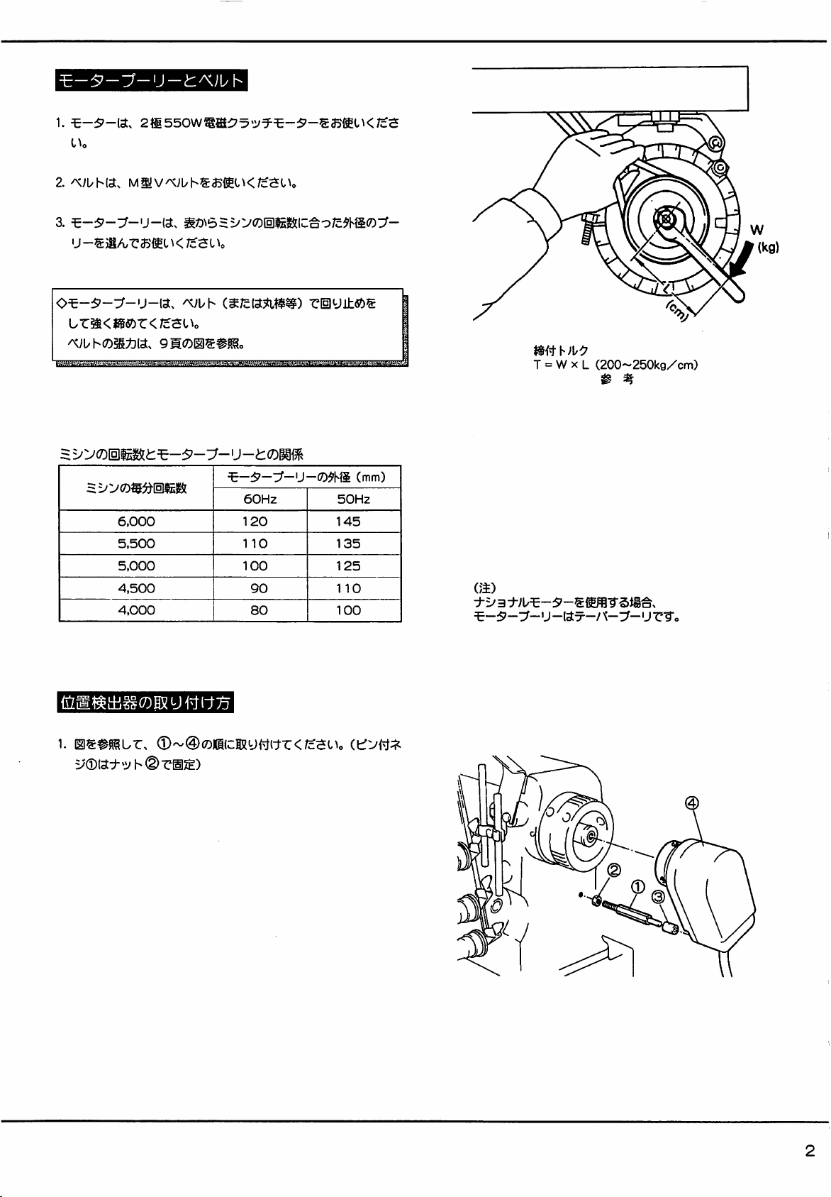
1.
2.
1^0
^;i/hia.
MSv/K;l/hsa®lK/c^c^o
u-S3i^^33m
o^-^'-T^-u-ia.
Lz^<msbz<ic-ai\o
6,000
5,500
5,000
4,500
4,000
K/c^t
^;uh
^0
(^/cia^ti^^)
60Hz
120
110
100
90
80
riiy±fi?)S
3^—U—t7)^hS
50Hz
145
135
125
110
100
(mm)
T = W X L
(a)
3
:0_5,_^_|j_|^^_;
—:5—^umjysi«a\
(200~250kg/cm)
^ %
>;_3;_ij-^-5-^
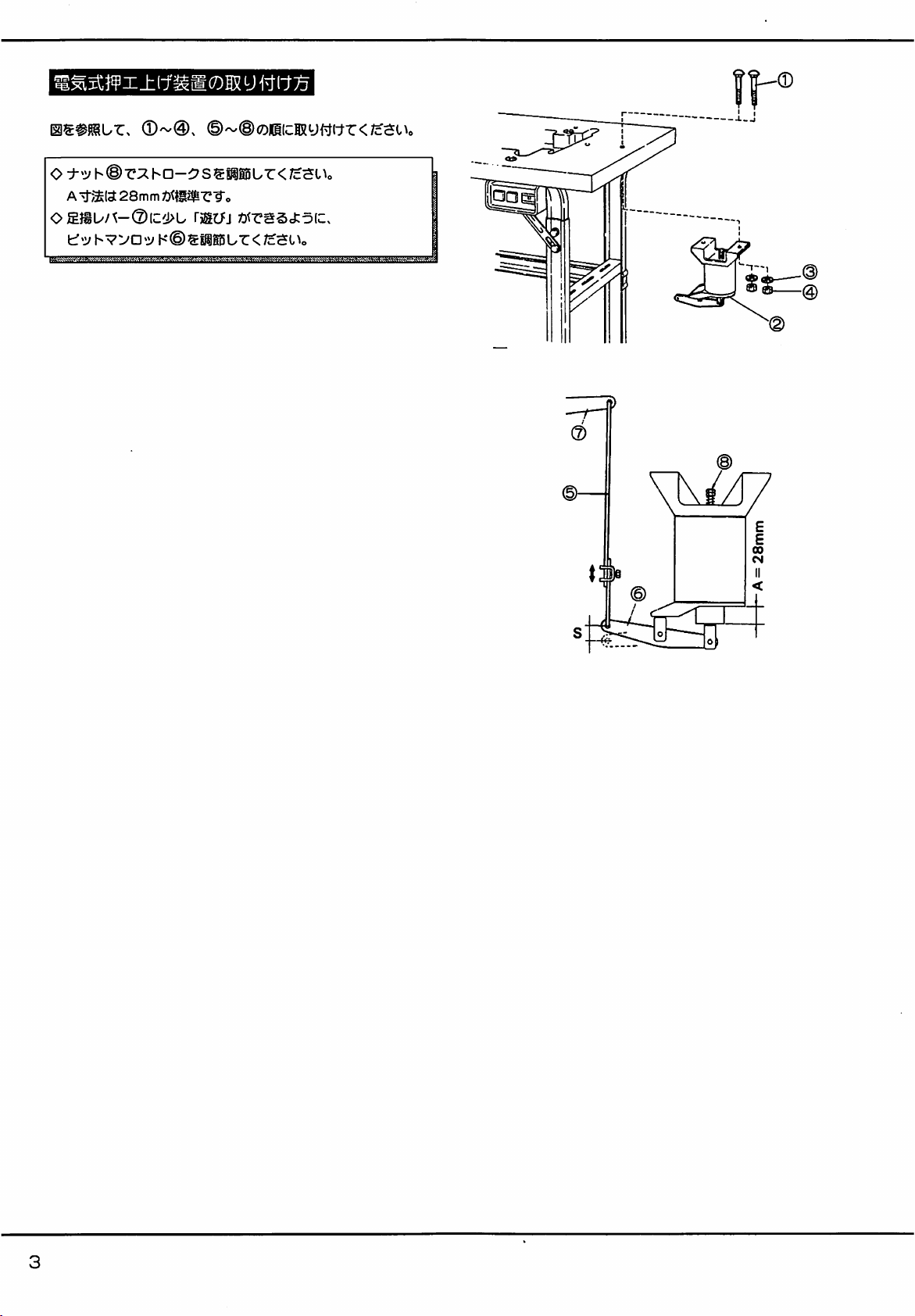
[«itii§iro®y«it75
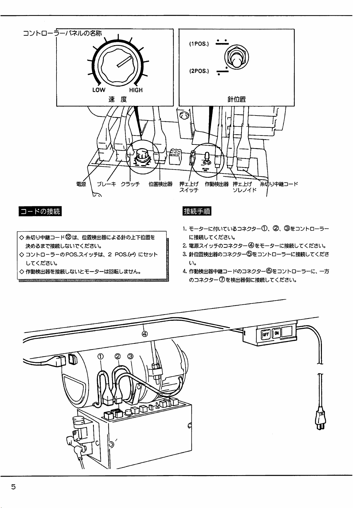
1.
©~@00ic;Kymr<;cauo
Q
Page 5
©
_)
G
32
m
u
)U
\0
V
t
@)@
©
UJUJ83-V
\t
o]
O
CO
Page 6
TO
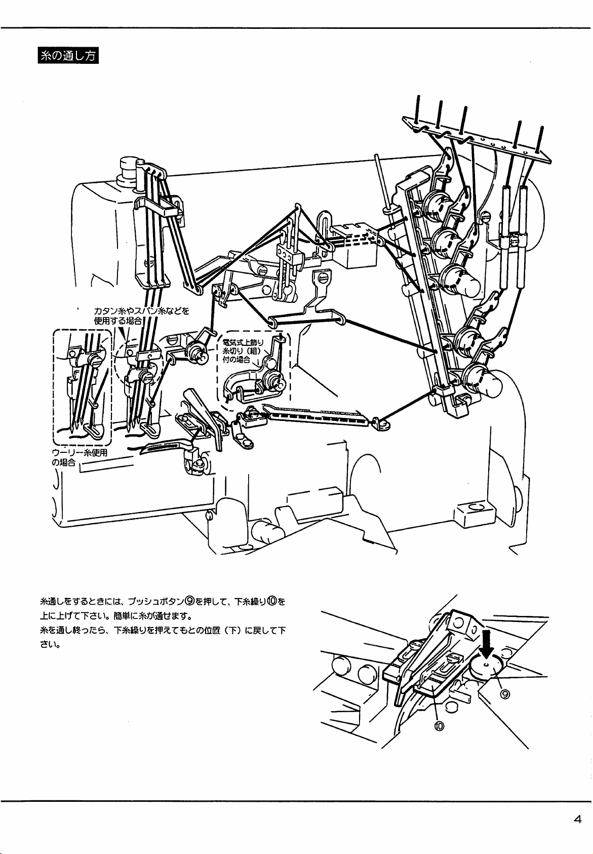
±(c±ifrTSUo
^SiiUlto/cB,
T^j^ys}¥^r=&i:0{jl®
CT)
ICMUrT
p
Page 7
\
©
@)
^ « n
n
in
J)
^
©)
lO
Page 8
n
3fe«)y
i
•
5.
(llfei:ili<7)M) H(CD-Ki:7U':/3^©5®fflUrBR
m-i^o
6.
/csuo
5l^o
roNj
roFFj
icur.
5v:^(^0^75[^®iii88ur<
mM:3:^^^-@^mzmmi.z<tc
(cLr</cSi^o
A
Page 9
@ H •IS
X
CSffi)
i
SCO
sfeB(?±®!ia5
(±!iBy®LRt)fX7-a±l
1.
tl/'^-©S^hL.
:i^y©®»r</cSlV
2.if±5Ej#.0iili5
ti-±5Ej5^r'±«)r<;cSUc
Z(Dt:B.
JVJK/rW-i/KDP^-i7i:T-A(^«EDWnru
^y©®i?g«?)r<;cSUo
3.
ifT5E;^0liii5
(^fe)
ro(Dg|5SteV+t-SM®04^/i:\(cte':;h
ur<;cat^o
§^•±5E,'^.t)^6$t(Clgi5
4.
®icM-ri:ffZ)rF5EKS"c<?±u^-ro
roNj
ur<7c3l
(cur.
y^iioyro
/\VKzrv^-;i/S(DUrP
^:S^;us4'3i{iz
5. }¥X^^VL/y-f'K(7D4'liD-K<?DD:;^::?5'-©SD:^hD-
5-
6.
S-
©^•vhD-^-ic;S^ur<;cai^o
7.
(g)
(:t3^5^3V)
h:iJ(c}gmur</cauo
(.m)
mizmmi^z<iz^i\o
-
7--:>
7
r 0 c t u r <
/caI^o
Page 10
tt-figl¥±®!Si5
(®ma±K6y
y
sy
©tii
1.
2.
3.
/cal^o
/cSUo
±\§±m
ur^ttSo
roNj
(cur.
mm:3:^os-
55>^'oi5i^^i^s5i^L.r<
(sm.
roFFj
(cur<;cSUo
:i^y®®§afi)r<;c$o\o
@)
±{jl®^l±i^<i) (Hfe) <^®a5®l2Vtf-SM®(^4^/C\(C^
t>t?,
4.
Tff
±{iz^0lii0
c±^±nmus%\zmmLz
7.3^U':^5^-sS9EriSic:G:si^ic;=^
^o
(#fe)
0®SI5gteVtt-gl[®0«(cte':^
l-UT:</c5l^o
<7z^i^o)
vs#-c0
ur^t^r
m
</c
o c y
5.
^ICil^i:ffOT5EiSr^±U^-ro
5-(C.
1^0
roNj
icur.
::75'-05Dyha-5-(Cg8cUr<7c5O^o
8.
iD(D3:^cps-^^^mzi-[^
(S)
ra:i^r:75'-®SDVhD-5-IC,
(5®)
sms±if6yjii«]fflA.cD^
^o
^s^iiy^^tLiU
FiUlC^mur<;c5
m[zmmLz<rzzsi\o
2.0mm
NEESLEPO^
!»»»€
VOkT'Nl*tl«
I"—-
/^lA
•Mi
M-M m
Vrt
1
-
3 4
(T^i3]y)
ON SW2
LF-PSA
12
W^^'0lcmz±:^V®^W^LZiy
:^'l'»:/5^®<7)ISW50NfiiJ(cii)[)y®^5i:^-5'-l3±ll6y^W —
yffl(c/3:y^-9-„
o
'E-s^-{^xmim(omiz[ty,^^^=j-is\N[toFF
0lXSg(c/3:oru^^o
(±g?y
Ci:
Ct C2 A
LF-PSA.**i»W
swi
12
3 4
C±
C1 C2 A
(±-T^«]y)
ON SW2
OFF
iSW CCH AW +1 -t-2 LKB HBK
®^ONilJlC±lf§
ISW CCHAW+1+2LKB
HBK
8
Page 11
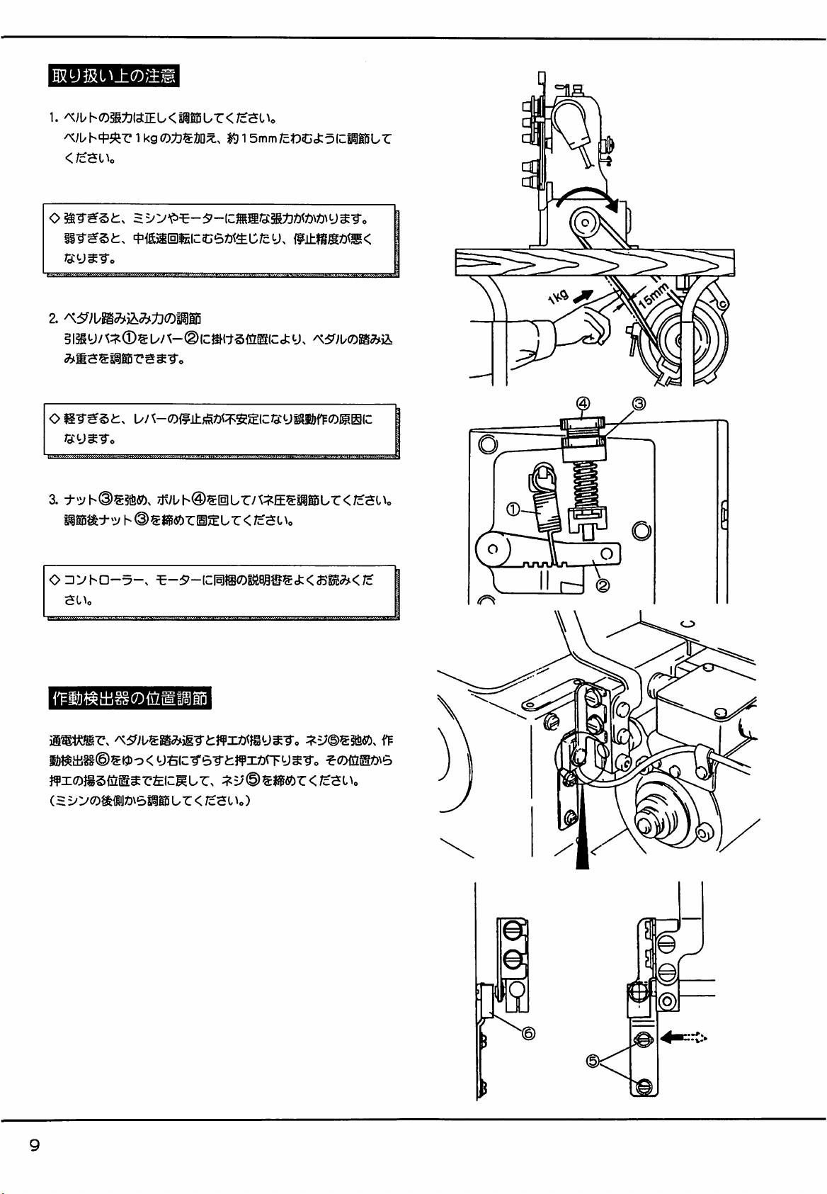
1.
^;Uh05gt}(3IEU<ilt5Lr</cHUo
1
kg
4^<£ji(s]^lcC6Z)<^D;cy.
/sy^'To
2.
^^)\ym^^^t}(Dmm
1
5mm
/c^OCctoCWUr
O
/ay^To
3.
Iigi5^:^»:^
ODbhD-5-.
i&^ttss(i)SK:)o<
b/
SSIC
^;^b@^0br/\:;^E5TObr</c^C^c
h@®«gfi?)rSlSbr<;c3l^o
^-5'-lc:|lfflOM®Sci;<a3§|^<;c
yaic-rs-rtjfxOTy^-To
^0D{a®z)\6
f¥x<D}i§(iz®^r'fcicMbT:, :;^=;©s3Sgfi?)r<;cSi>o
CH
bbOMiJZ)\6llli5
b r
</c^l
U)
r\
Page 12
0
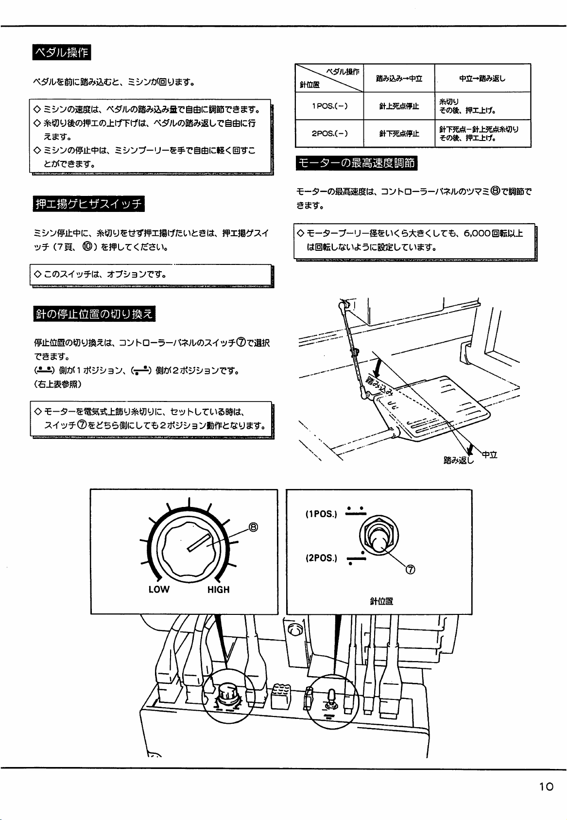
55^^'0)ijg(a.
o
^^^)y^0^¥x0±lrF(1'(a.
O
S£^v0<?±'f'ia.
nn^vBrn^o
^5^;i/OS^)iabtfiriS(csiSDrssTo
^5^;KDiga»^ijgur@fiic'f7
==^y3^-'j-®#-cgfiii:g<(sl-rc
1P0S.(-)
2POS.(-)
^-5'-®*S5igl
SCTo
tf±5&iSff±
t)T5EjSff±
^«)y
ffxXCfo
StT5&S-if±5&S^«y
^(D»,
)fx±(:fo
^yyw±^iz.
(7Mx
OC(7);^-f':/TO.
rg^To
(ii)
ijfin
(S±i
o
^feiioijgtj-rffx^i-j'/cuinsa.
®)
S}fUT:</c$Uo
:i-3^5^3>'r"9-c
• V
ha-5-y
7j<=;v3X
(t^)
jfxji^;^^
iJ^<2Aj<5;=/3:^-c-ro
hurc^sB#«.
l.l.|l|lMilM«.M.»U«»B«»ll.UlUUJ»l.iMllllMHIWmjlHI.HI
riiJR
O
finite
(IPOS.)
L/SCl 5
(C^
6:^g<
U r I
^^To
\
UrB,
e.OOOISigUU:
(2P0S.)
LOW
HIGH
tf-^D
10
Page 13
Vbyf
1.
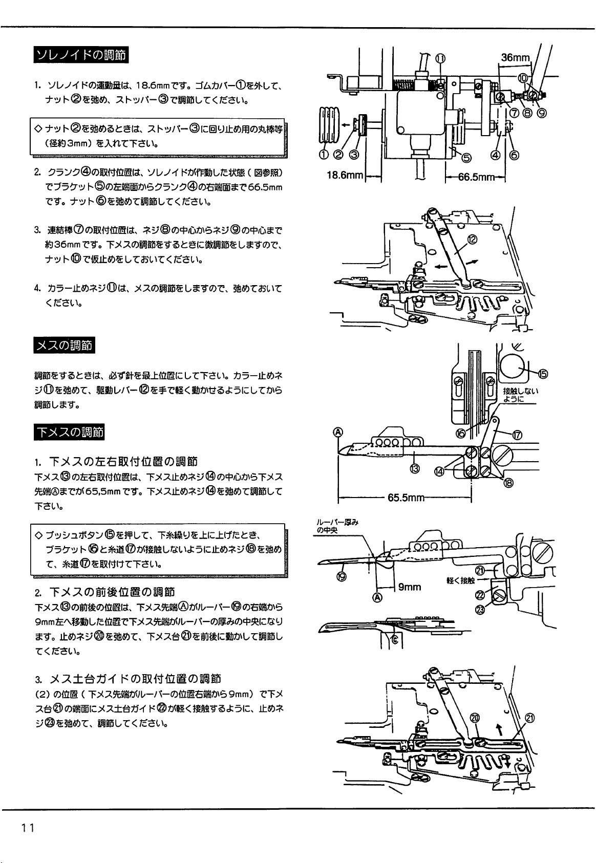
VL/y-<h'0)iIi)a«.18.6mmrTo
;^l-'2^/^-@-C»Ur</c3Uo
(SI?)
3mm)
SAnrTSUc
36mm
zTAij/'^-Os^Kur,
y
r-To
•t^^h<B^^sbzmmLz<ic-ai\o
3. jl^g^l®0TOfilS5(as :^V<B<D^iL\t\e^V®(r>^€\^Z
m
36mm
±'V h ®
4.
</cSl\o
v^o
ris±«)Surasur
:^^(DmB^\^m^o)z.
§
tsicMSis
</cSUo
u
mro)z.
sfifiorasur
^:^roili5
W5^5i:S(a.
iej-rtf5g±{il^lcUrTaUo
igi!)b/t-©s#rs<i&Z)\t?5ci:o(curz)\6
1.
Tx
® la.
65,5mm
TSUo
o
•:JvVn.iTsSv©^n\^z.
h ©
i:
TTo
©
T^®
T^^ys±ic±if;cts.
Z)<}g84
LG:t
)<i:
(D^iC\t\e>T>^
SSfifi^riHSBUr
5 (c±«):^^y ©
18.6mm
® / L
)\,-j'(-B^
65.5mm-
rfQOQ.X)
0
—66.5mm-^
©-fT^fctXr
—i
J:5IC
2.
T>(;^0tu^<i5e(Dili5
T:><::^®oiu^(?)OTiav
t^7St^®U)b-i\-©
±ISb:^V®^^<SbZ. T^;^a©€8U^ICS)Z)\U-CPIi5L
r</c$i^o
3.
(2)
(Dim(TX:^5t3S^^)U-/^-(^fi^a!l^\69mm)
:^^@(D^m\ZXX±'^tS'^
y©S3{fi«)r.
1 1
K(DIS^^<ize(Diil(5
h'®Z)<Sl<^8®-rSJ:5IC.
giiSur<;cSi^o
rT:><
±5^^
S<gM
—
@
Page 14
A,T>^:^±Tm
(2)
(Dm.
( ) "CT^;^©
t^lS®»<;U-/K-®0±®IC^<^g4-rScfco(C.
±fi?):^=;©s«r.
l,^c
5.
22mm
r-To
h@S5ftfiOr.
ss±Tici&Z)M/rpg5ur<
liSBUr
<;cSl^o
f/^
h@0
/cs
-m[^mr<Dv.
6.
±l50llg5Z3<^a?*SL/;c6.
o
T>(:^©Dm^mm(DizB{z.
7.
i\rd:i\im
OT^rammr-^o
l^o
si^urT^Oo
1mm^SCilo
(m^m)
)X(DZt:^mV&\.^Z<Jc^l\o
h'
® ®
vz^3^^:j^(B(D^mmD\e>ti3-®^
pieurTa
®
(B)2mm
®n0Dj'
L
—Ij-
©1mm
—
—3mm
o
0
0
12
Page 15
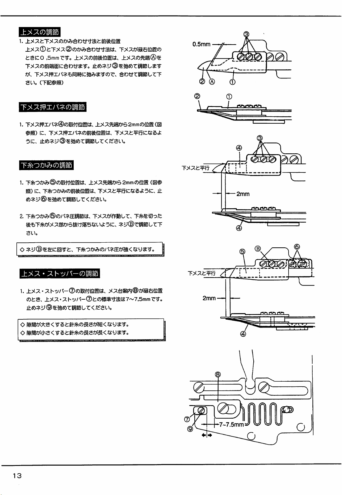
1.
0.5mm
i:g(CO
T^::^(7)i5M(C^Dt?^-ro
SUo
T>^;i)¥i/'\:5^®!ii5
1.
oic.
1.
RS)
«):;^=;©S5tfi«>riigi5ur
^=&T3feZ)<x::i»6t£(t^5/d:iu5ic>
SUo
,5mmrTo
T><::^}¥i/t:i^t)PKic»^-r0r\
(TiB#S8)
IC.
T;>^;^}¥x/t:i^0gO^Gl^(a.
±ett:^v®^^<!bzm^Lz<rc-a^\o
IC>
±>^^(09cM®^
±fi^:^y®S§te«)rPS0L^T
•g^^t^rissBurT
±^^9cMt)\e>2mm(DiiLm(.m
T>(;^t¥'f7lJ:Q:Scfc
±y;?.$t^t>\62mmO{iIg
T><;?.i^¥?jli:/3:5a:5IC.
</c3t\o
rPlBurT
(0#
©
\
^—t
Ty:^ege
,^7]t'{
rVM-u-irv«i
@
A
\
t;
±
2mm
cacacQL
o :t^s;®s&(c(5]-r^:x
±>i.:x
1.
ots.
•
±>(;^•
v ®
::^
^3fi«)r
T^ot\^<Dj\:^Eym<w^-^c
^-®i:o^^^^£ia7~7,5mm
M Ur <
/c^l
rTo
^zrrr:::::
2mm
—
T
t
!i
I-
7~7.5mm»
13
Page 16
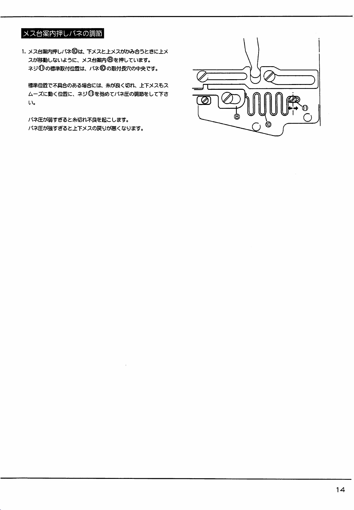
1.
:^Z)^^$i^)U/3:l^cfc^(c,
T>^^t.±>^:^m\^^oii€{z±>^
:x:^^3gF«9®s^¥Url^^•ro
A-xizm<mm[z.
J
:^5;(Q)g»rA:t^E<jDiggi5surTa
jgC
14
Page 17
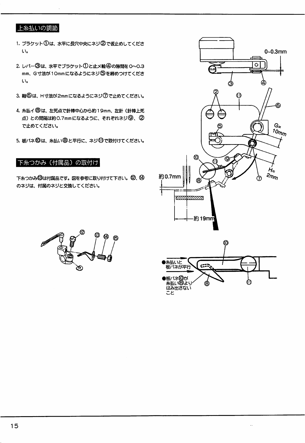
1. 7j<5ji(c^7^c|:^ic:i^=;(Drisu:«!)ur</c5
l\c
2.
L//t-®ia.
mm,
7j<5|ir3^^^»i'h©fcll::><M@OMSO~0.3
G^^Z)n0mm(CG:§J:5«v(i)g«l«)O(tr</cS
0~0.3mm
3.
4.
, H^mti^2mmlZU^<i:3[Z:!?.VQ>V±SbZ<Jc^l\c
m-rSia:,
£^^S^t^^?'^'/^:^Z)^63K319mm,
£tf
(if^±5E
j^) tW^PiraO.TmmlClGScfcolC, (D
r±«)r<;cauo
5.
t^ox)^^©«{^j1d°q-c^o
mLi^(Bt:w-^[z.
(WBS)
©ISI'JW
0€#%icaRy(^(trTSUo
:!^vOvmmz<m^i\o
® ©
®,
®
sg
0
0.7mm
^zzzzmzzzzzi
»gi9m
%
ct
15
Page 18

1.
10mm(c:^5; ®
rffiy
f^Cfr</cSl^
® ic:i^y @
rsieur
</csi
\o
10mm
3. M^PMi:^§fi;><®<Dm<^MZ)to~o.5mm(cQ:§cfc5(c;. b
/
4.
fa@)iaA^j^Z)l37mm(CG:5ctDlC:i^=;®®±fiOr</c^Fl^o
t}Sy^<DMa
E =
o-
^ y =6JS<TOu r
o
±fifey^i2)y/3:L(^^^
r=6,
o±®6y^i5!]y^yroii^
G =
wur
6.5mm,
u
^iPS^(7/^:o^{5lSlci2':^hUr</cal^o
15mm(CTOUr<;cSl\o
^:75b::7(i)0:;^y®sjgfi?)oitr</cSUo
B =
6mm,
C =
7mm,
F =
9mm(CiiML/'C<7cSUo
</c
s I \o
D=
8.5mm,
±ies^;^
®
©
o
16
Page 19

^^^t^r</cSUo
(iES{ii®(Z)wia.
9MS#RSur</cSUo)
0.5mm
h0.5mm
(e
0
17
Page 20

0)Mlll
"t: Fff HI
DD
UI
9t
s m 3
P a
«S «
r?t
/\
Ul
f9t ^
m 3 ^
w ^ ^
^ ^
rS W
# S
c wf m
s fn
H
c
u
s
ono
\/;
00
Page 21

l§IO)ci:o(c
;;tr-KDVhD
;^t:-
[<3y
hn-^-Qia^
t:-h'Sl^li5US"§"<,
h'
;^t:-
^rosJiiCct
e-Sfeic
K=>i)
19
y.
±T><
ut:-h*=P)
liS^^>ii^^mL^•ro
ic(iug-prz)\6,
u
/so/cy.
©
^>t?ica(c:
C^t^-
Page 22

^ui
5~7kg/cm2
!^u±c±Z}aj^-ro
(cM
Ur</c^O^o
®
•?(Z)Wc$mES
®
o
ip-E^±c:f5i:gia,
oxT'-Eswstsia.
t)'jS-lDi^W)L^'^(DZC:)iMXJz^{,\o
^:;'V5®sa:^f^ic(iu-c<;c5Uo
£:5iqnci5]ur</c5Uo
KL/Vrostdd
s^EXiasicffurM
U
ur</c$
20
Page 23

sms:±g5
y y
ffltisoli;
® ®
^150
2.
•rse
3.
4.
5.
gOTMrS<iS<:?®5ilS-r5o
A^/^=120mm
6"^^=
59mm
G^^=13mm(c:/d:S1i(CU/^-®S|S)S-rSo
Osnmso
(a)
0-U-M551:$:j&aA-a(CiiDn55®5i^-rSo
ib)
mmmLizmz-i5(DBoJco-u-mmvm^n?>
?s?ii^"rSo
iogm±o
(J^ie)
21
Page 24

»H!
sr
XI
y m
^ y 3
y K
@1
g
>J
^
/fl
n scr
»tn
C I
s ©
h-
©^
S
b y
i ®
|B
Page 25

±treu^®y,
1.
by^-(D^Tie(o^/"£(c^i^rBSf^it§o
A =
23mm
(0-U-5'-1'3^)
2.
zcomzji^trv
ySo
3.
HbbSjigur.
a
;?.3/b':y5^-®j$t
•^jss3i2<-r5o
h ® g±fio:;^b' (D
h®
±ifByMyg^sii)fp3t?5o
vmm-^^0
h'@i:<DMia2mmgJg(C^
(Eioas)
i
(7)Bf
A =
30mm
cty^M^nai^isoianoA
(HFgB)
l§l(7)Af/^S:g<T5o
—
2.0mm
23
Page 26

II
• 13
I
VI/
K
iT'-auT^groEss
(£iJ±S^®y
;
IT-it)
•
H • H
(l»l^)
'pmn-ii
m)
i§i(^j:o(c@5i®sur
imwm.
^oDfteoDnsis^/^ia.
^irc#i(is#Rsur<;c5Uc
<
;cSt\o
5~ioM0mmscuTgg(^D-
24
Page 27

C"
fsn
r
rS
ni
"H
na
U M
h" w
ri
3
9t
c
'-SSf
r\
A
\J
I
I
>J
fX
nt
m
fSft
(X
Si
y
IS
I
n:
a
C
n;
I
II
V.'
"t:
Ti
m
«4
I •
541
C IT T-
S >J
•§
«4
e>J
C
' nil
It
e>j
S
ri
H ' U
n S
0
C
a I
fit
-t;
I
1 wt
T.
^ im
u
©
U 01
rr
I
•
*0
T
^ d
^ I
w
\C
H-
nil
II
n
•HD
9tt
r
vc4
01
Vi'
®
y.
m
^
5M-
® y
u;
g Kt
•>
T
®
0
nil
c
y
It
"H
3
"nf
ri
gh
;S
Pft
®
a
r\
3
n:
-n
yi
nn
e>j
fv y
A
<]
$}
541
3 I
rit
0
C
9?
a
01
•>
Sio
III
©
n
n:
E
§ m
i
C
r|
:s
v3
s
n
Page 28

1. CgJ
5^X
±^VVimLZ<Jc^^\o
2.
z>^vo.
BS{^(tr</c^t^o
-DVO
ibS-o^D.u-s-(B(D'y^^®^±{z^\-o^^t:
'ui
tim^iLZ.
5~7kg/cm2
O
X7-Es±(:f§i:g(a.
o
O
ziyyiy^u-^-mo^xy-m^m-oz^.
-Z)^^orustgia>
tjys
-Z)^i'pi!jL
'i>u±ic±Z)aj^-g-o
(CM
Ur <
tc'Sl
V^^®^^mzMLZ<1z-^l\c
£;5(^(ci5]ur</c5c^o
/v\/yyy=fx—y-^w^iis
mr(Dzz:)m
< /c s i
0~0.5mm
0~0.5mm
rti^
®
^n-ymzoLy
T5lu(c:igffiogf7j<ffi7rv-;^©®^iasic}¥LrgfaiLr<
C^o
/c^
26
Page 29

(\D
Machine
models
W664-08,33,358,81
W644-01,03,05,08,33,358,71,81
W664-01,03,05,71
W664-01,03,08
W664-08,33,358,81
W644-01,03,05,08,33,358,71,81
W644-01,03,05,71
W664-30,32,34,35A
W644-30,32,34,35A
W664-32
W664-01,03,05,08,33,358,71,81
W644-
01,03,05,08,33,358,71,81
W664-30,32,34,35A
W644-30,32,34,35A
W664-01,03,08,
W664-
01,03,08,358,71,81
W664-30,34,35A
W664-33
W664-32
UT
UT109
UTIlO
UT111
UT211
UJ212
UT312
ufsis
UT314
U^15
UT316
U^7
UT320
Ut321
UT333
UT334
UT414
UT415
UT434
UT435
UT436
Ut437
UT438
Uf439
UT440
UT^I
device
Thread
Electric
trimmer
type
W600/UT
mechanism
Pneumatic
type
Top
cover
Electric
(Component
thread
trimmer
mecharvsm
type
Pneumatic
type
Thread
Electric
wiper
type
list)
mechanism
Pneumatic
type
Foot
Electric
lifter
type
mechanism
Pneumatic
type
I
MITSUBISHI
LIMI-STOP
I
PANASONIC
PANA
SERVO
Motor
Motor
Motor
PEGASUS,
Page 30

1
MOTOR
PULLEY
ANDVBELT
I
Following are the specifications for the motor and V belt.
1. Motor: Double pole,
2.
V belt:
Type
3.
Motor pulley: Select the proper motor pulley for the speed of
550W
clutch motor
M
the machine to be used by referring to the table
shown
below.
OWhen replacingthe motor pulley, fix the motor pulley with the
V belt or a rod and then tighten the nut.
Refer to the illustration of page 35 for the belt tension.
Relationship
Machine speed(s.p.m.)
6.000
5,500
5,000
4,500
4,000
between
machine
speed
and
motor pully
Motor pulley dlameter(mm)
60Hz
105
95
85
80
70
50H2
125
115
105
95
85
Tightening
T=Wx
(T should be
(Note)
Install
the
PANA-SERVO
pulley of
L
motor.
torque
200
tapered
to 250kg.cm.)
hole for
the
li
1. Install the position detector by referring to steps© to ® in the
right illustration.
(Fix pin screw
(g)
with nut
©.)
Page 31

INSTALLING
Followsteps® to@ ,and© to(
(See the right illustrations.)
THE
ELECTRIC
PRESSER
FOOT
LIFT
O Adjust stroke "S" with nut
To
obtain
the
standard
®.
stroke, diniension"A"should be 28nim .
O To producea little play on foot lift lever (2), adjustpitmanrod
29
Page 32

THREADING
For
spun
cotton
thread
thread
TO
and
For woolly
Press
machine easily.
Pressthe looper
the
machine.
thread
pushbutton®
/
and
lift
thread
take- updownand
o
I
looperthread
I Ifthetop cover
' thread trimrrer
I
(assy^is
take-up (©to
replace
it afterthreading
i^d;
thread
the
30
Page 33

Descriptions of
the
control box
(IPOS.)
(2P0S.)
LOW
HIGH
Speed
Powert
CONNECTING
CORDS
O Do not connect threadtrimmer relay cord
lowest needle positions have been determined by the position
detector.
O Set the POS. switch on the control box to 2 FOS.(r^).
O Besure to connect the operation detector to the motor to run the
motor.
BraKe
Cutch
()|)
until
Position
detector liftswitch
highest
and
Needle
Presserfoot
CONNECTING
1. Connect connectors
Operation
detector
box.
position
Presserfoot
liftsolenoid relay cord
STEPS
®,
(§) and O of the motor to the control
^Thread trimmer
/
2. Connect connector@ of the power switch to the motor.
3. Connect connector (§) of the position detector to the control
box.
4.
Connect
connector © of theoperation detectorrelaycord to the
control box and another connector(2)to the operationdetector.
UD
31
Page 34

n
ellow
green
Whrte
and
stripes
Red
Relay
CM
®
Yellow
n
cord
, .
Black
(short)
Hi
Thread
solenoid
trimmer
'
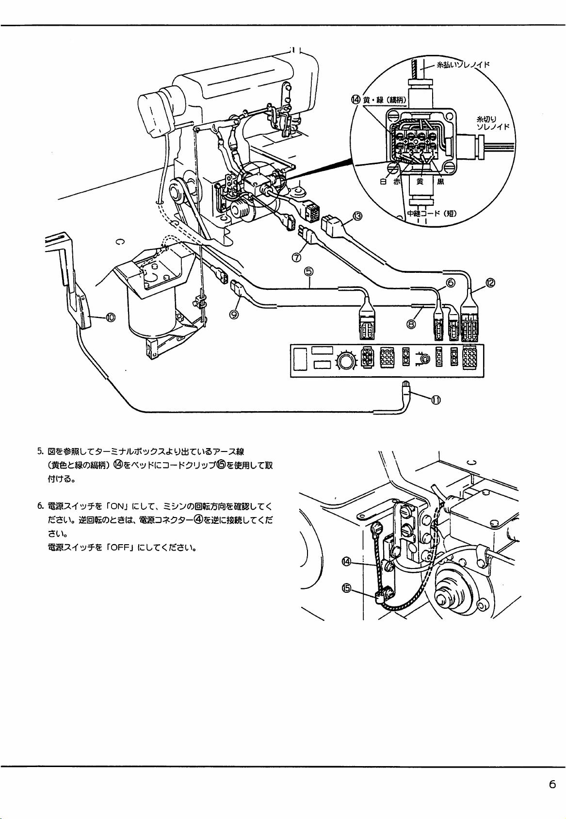
5. Fix groundwire@ of yellowand green stripeson the
bed with cord clip
6. Turn the machine on to check the rotating direction.
If the
machine
connector@ upsidedown.
Turn
the
machine
(Jl).
rotates
off.
in the
reverse
direction,
connect
machine
power
1i>i
ii
32
Page 35

green
stnpes
Whtte
Red
_ , Relay cord (short)
Thread
tnmhter
solenoid
Ye
low
Back
n
NEEDLE
POSITION
ADJUSTMENT
(without top cover thread and for pneumatic top cover thread
trimmer)
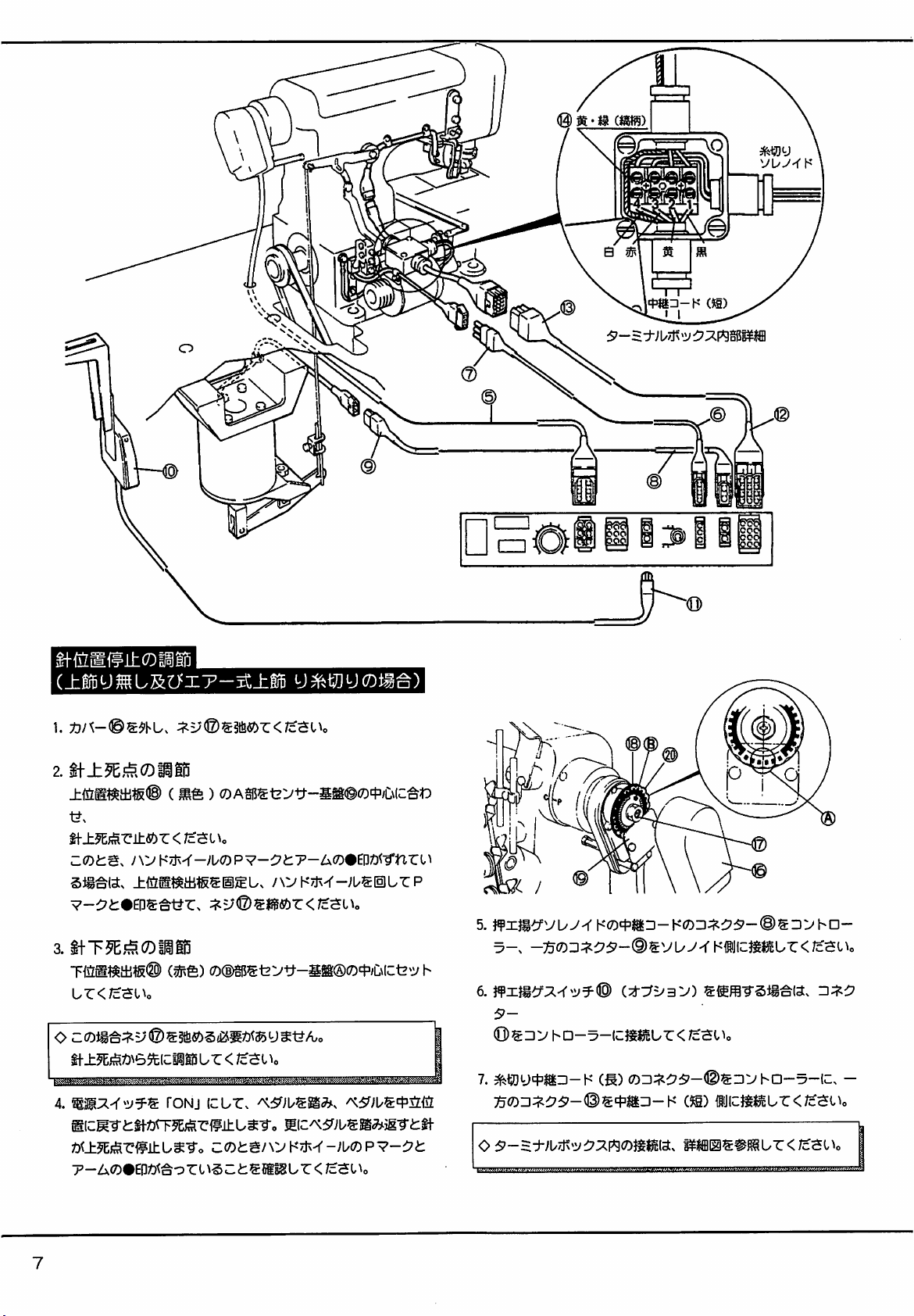
1.Removecover ® and loosenscrew
®.
2. Adjusting the highest position
AlignA portion of upper positiondetectingplate® (black) with
the center of sensor baseplate © and then set the needle at its
highest position.
If
markPon
the
handwheel
and
the
black
circleonthe
arm
do
not align, fix the upper position detecting plate and turn the
handwheel to align mark P with the black circle, then tighten
screw
®.
3. Adjusting the lowest position
AlignB portionof lowerposition detecting plate @ (red) with
the center of sensor baseplate A.
O When adjusting the lowest position, there is no need for
looseningscrew
®.
The highest position adjustment must be made first.
Insideofthe
termina
box
•
'1
5. Connect connector(D of the presserfoot lift solenoid relay cord
to the control box and another connector (§)to the solenoid.
6. If presser foot lift switch © (option) is used, connect connector
O to the control box.
7. Connect connector © of the thread trimmer relay cord (long) to
the control box and another connector © to the relay cord
(short).
OPefer
4. Turn the machine on and treadle in the neutral position. The
to the illustrationofthe insideofthe terminal box shown
above
for
the
connectioninthe
needle stops at its lowest position. Then heel the treadle to stop
the needle at its highest position, and check to see if mark P on
the handwheelis aligned with the black circle on the arm.
terminal
box.
33
Page 36

NEEDLE
POSITION
ADJUSTMENT
(with electric top cover thread trimmer)
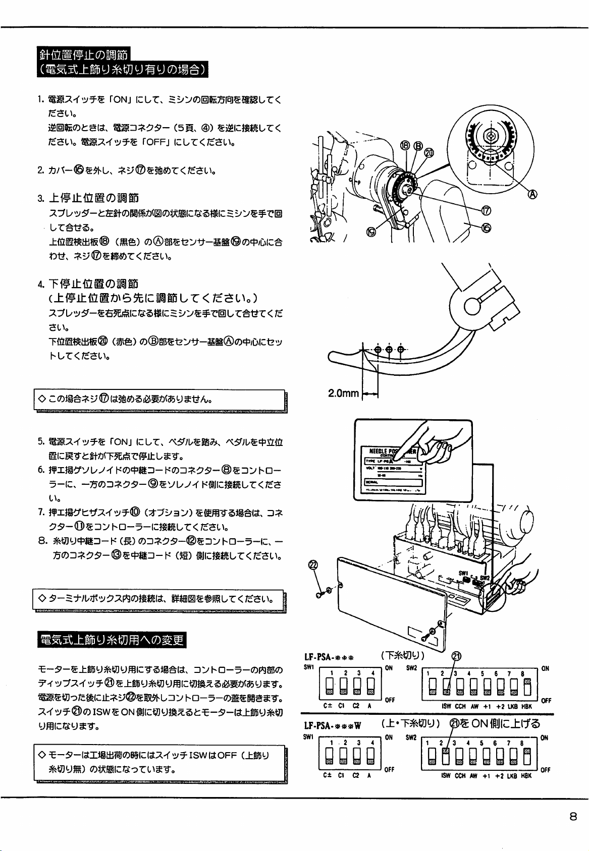
1. Turn the machine on to check the rotating direction.
If the machine rotates in the reverse direction, connect power
connector(See illustration @ of page31.)
Turn
the
machine
off.
upside
down.
2. Remove cover © and loosen screw
3. Adjusting the highest position
©.
Turn the handwheel by hand to make correct relationship
between the spreader and the left needle as shown in illustration
.Align A portion of upper position detecting plate ® (black) with
the center of sensor baseplate © and then tighten screw
4. Adjusting the lowest position
®.
(The highest position adjustment must be made first.)
Turn the handwheel by hand so that the spreader will reach its
extreme position to the right.
Align B portion of lower position detecting plate @ (red) with
the center of sensor baseplate A.
O When adjusting the lowest position, there is no need for
looseningscrew
©.
5. Turn the machine on and treadle in the neutral position. The
needle stops at its lowest position.
6. Connectconnector
(§)
of the presserfoot liftsolenoid
relay
cord
to the control box and another connector (§)to the solenoid.
7. If presser foot lift switch ® (option) is used, connect connector
© to the control box.
8.
Connect
connector
© of the
thread
trimmer
relay
cord
(long)
the control box and another connector ® to the relay cord
(short).
2.0mm
IMI
jlWM.
1
to
<C>Refer
Change the motor application with one of dip
control
Turn the machine
to the
illustrationofthe
21) for the connection in the terminal box.
TO
SET
THE
MOTOR
TOP
COVER
box.
THREAD
off
and remove screws © and the cover of the
inside
APPLICATION
TRIMMER
of the
TO
terminal
THE
switches
ELECTRIC
control box. Then move (ISW) of dip switches to ON in order
to apply the motor to the top cover thread trimmer.
O Dip
34
thread).
switch
ISWisfactoiy-set
to OFF
(without
box
(page
© in the
top
cover
(Underbed thread trimmer)
LF-PSA-»*»
swi
C±
C1
02
LF-PSA-**«W
SWI
1 2
C± 01 02 A
A
ON
OFF
ISW
CCHAW-t-1+2LK6
Set
dip switch
ISW
OOHAW+1+2LKB
HBK
(0)
KBK
(Topcover thread trimmer and underbed thread trimmer)
to ON.
ON
Page 37

BELT
TENSION
ADJUSTMENT
1.
Belt
tension
Adjustthe belt tensionso that 1 kg pressureon the center of the
belt allows approximately 15mm deflection.
O Excessive tension may overload the machine and motor.
If
the tension is not sufficient, the machine at medium or low
speed may not run evenly and also the needle may not stops
correctly.
2. Treadle toeing force adjustment
The treadle toeing force can be adjusted by selecting where to
hook tension spring
O If the force is tog light, the stop position of the lever may not be
fixed, causing trouble.
AND
TREADLE
(X)
over lever (§).
TOEING
FORCE
I
n
3. Loosen nut (3) and tum bolt @ to adjust the spring pressure.
Then tighten nut ® securely to set the spring pressure.
O Read and study the instruction manual packaged in the control
box and motor carefully.
POSITIONING THE OPERATION
The presser foot is lifted up by heeling the treadle when the
machine is on. Loosen screw (§)and slide operation detector
the right slowly to lower the presser foot.
Then replace the operation detector to the left until the presser foot
is raised. Tighten screw
(This adjustment should be made from the rear side of the
machine.)
©.
DETECTOR
<§)
to
1
Page 38

TREADLE
Toeing the treadle starts the machine.
O The machinespeedcan be adjusted freely by the toeing amount.
O The presserfoot can be lifted up or down readilyby heelingthe
treadle
after
the
thread
has
been
trimmed.
O The machine pulley can be turned by hand easily while the
machine is stopped.
PRESSER
FOOT
LIFT
SWITCH
To lift the presser foot up without trimming the thread while the
machineis stopped,press presserfoot lift switch
®.
(See illustration® of page 33.)
O The presser foot lift switch is optional.
Treadling
Needle
positten^^^
IPOS.(-)
2P0S.(
-)
ADJUSTING THE
Toe
treadle-•
Stops
position.
Stops
positions.
MOTOR
Neutral
at highest
at lowest
MAXIMUM
Neutral-•Heel
Thread
trimmed,
presser
foot lifted.
Stops
at lowest position. —
Needle
goes
position to trim thread, and
then
presser
up at
foot
treadle
then
highest
lifted.
SPEED
The motor maximum speed can be obtained by dial 8 on the
control
box.
O The motor does not run at more than 6,000 r.p.m., however
large the motor pulley diameter is.
SELECTING THE NEEDLE STOP
POSITION
The needle stop position can be selected by switch (2) on the
control
box.
(•2-i)
indicates 1 position and indicates2 position.
(See the table shown on the right side above.)
O If the motor application is set to the electric top cover thread
trimmer,@position
selecting eitherofthe two positions.
operation
canbealways
performed
by|
(IPOS.)
(2P0S.)
Needle
position
To
heel
the
Neutral
treadle
©
36
Page 39

ADJUSTING
I.The
amountofthe
Remove
rubber
THE
cover
SOLENOID
solenoid
® ,
solenoidby meansof stopper(§).
movement
loosen
shouldbesetto18.6mm.
nut
<§)
and
then
adjust
36mm
the
0®
OWhen
2. Position crank @ so that the distance between the left end of
inserted
loosening
nut@,an
intostopper® inorderto
approximately
prevent
3mm
from
rod
should
rotating.
be
bracket® and the right end of crank @ will be 66.5mm with the
solenoid activated as shown in the right illustration. Loosen nut
® to makethis adjustment.
3. There must be a 36mm distance between the center of screw ®
andthat of screw
Since fine adjustment is made when adjusting the lower knife,
fix the connectingrod temporarilywith nut
4. Loosen collar set screw
ADJUSTING THE KNIVES
The needle should be at the highest position of its travel to make
this adjustment. Loosening collar set screw
drive easily by hand. Then adjust the knives.
(§)
in orderto mountconnecting rod(2).
®.
(Q)
in order to adjust the knives.
(Q)
can make lever ®
7r
18.6mm
—66.5mm—
©
Do
each
not
touch
with
other.
LOWER
1. Horizontal positioning adjustment of the lower knife.
KNIFE
The distance between the center of lower knife set screw 0 and
tip A of the lower knife should be 65.5mm. To make this
adjustment,loosen lowerknife set screw
ADJUSTMENT
0.
OPress pushbutton0 to raise the looper thread take- up, and then
install thread guide 0 by loosening set screw 0 so that bracket
16and thread guide ® will not touch with each other.
Z
Front-
to-
back positioning adjustmentofthe lower knife.
To position lower ® knife front to back correctly, tip A of the
lower knife should be centered over the looper when tip A has
moved9mm to the left from the rightedgeof looper
®.
This adjustment can be made by loosening set screw 0 and
shifting lower knife holder0 frontto back.
3. Positioning adjustment of the knife holder guide.
With the lower knife tip positioned at the place described in
above (§)(9mm away from the right edge of the looper), adjust
knife holder guide @ by
loosening
set screw
0.
Be sure that
knife holder guide @ contacts the end surface of lower knife
holder© slightly.
Center
over
®
the
tip A
looper.
r-ZZl—
65.5mm
Light
©
contact
——
37
Page 40

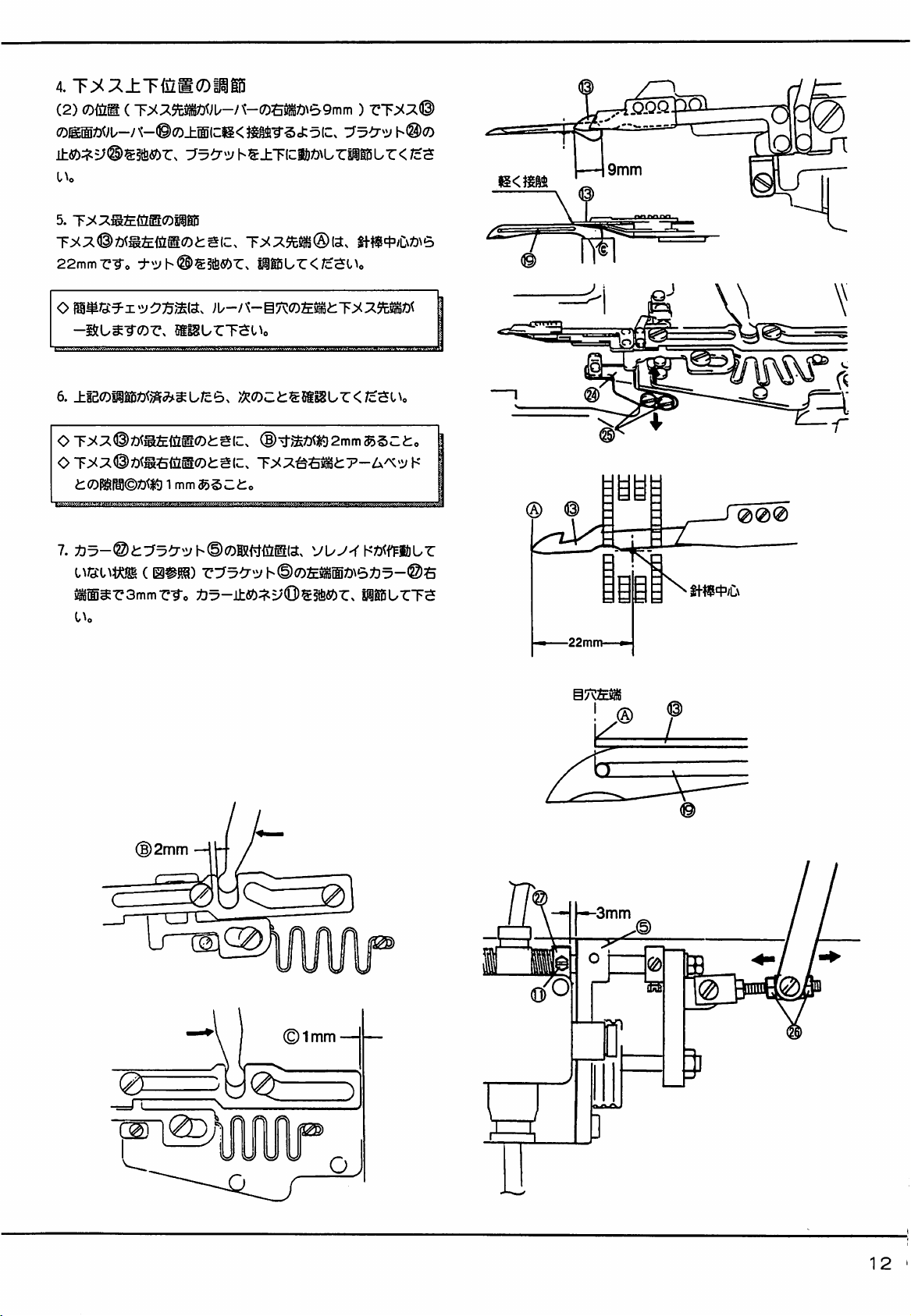
4. Vertical positioningadjustmentof the lowerknife.
With the lower knife tip positioned at the place described in
above 2 (9mm away from the right edge of the looper), move
the lower knife up or down as required by loosening set screws
® on bracket ® to make this adjustment. Be sure that the
bottom surface of lower knife ® contacts the top surface of
looper®
slightly.
5. Adjusting the lower knife at the extreme left end of its travel
With lower knife ® at the farthest position to the left,loosen nut
@ to adjust the lower knife so that the distance between tip A of
the
lower
knife
and
the
centerofthe
OTo
make the above adjustment easily, check to see if the left
needle
bar
willbe22mm.
edge of the looper's eye aligns the tip of the lower knife.
6. Confirm the following after the above adjustment has been
made.
ODimension B should be approximately 2mmwith lower knife®
at
the
extreme
OThe
clearance between the right end of the lower knife holder
and the arm bed should be approximately Imm with lower knife
left
endofits
travel.
® at the extreme right end of its travel.
Light
contact
® ®
(g)
Centerofthe
needle
bar
7. Loosen set screw
(Q)
and then position collar @ and bracket (§)
when the solenoid is not activated (see below). Make sure that
the clearance between the left end of bracket® and the rightend
of collar (§) is 3mm.
(B)2mm
(Z>
(g)1nim —
-Left
edge-^
of
the
looper's
eye
o
Q)
0
38
Page 41

UPPER KNIFE
ADJUSTMENT
1.Overlapand front- to- back positioningadjustments of the upper
and
lower
knives
This adjustment achieves the correct overlap of upper knife ®
and lower knife @ . There should be 0.5mm when the lower
knife is at the farthest position to the right. To adjust the upper
knife front to back, align tip A of the upper knife with the front
edge of the lower knife by loosening set screw @ . When
making the above adjustment, the lower knife clamp spring can
be loosened, adjust the lower knife clamp spring simultaneously.
(See the following.)
LOWER
KNIFE
CLAMP
SPRING
ADJUSTMENT
1.Position lowerknifeclamp spring@ 2mm to the right from the
tip of the upper knife as shown in the right illustration. Adjust
the lower knife clamp spring front to back by loosening set
screws
@.
Be sure that the lower knife clampspring is parallel
with
the
lower
knife.
UNDER
THREAD
HOLDER
ADJUSTMENT
Parallel
lower
0.5mm
with
knife
the
C
/Ll^i—i
2mm
1.Positionunder thread holder (§) 2mm to the left from the tip of
the upper knife as shown in the right illustration. Adjust the
underthread holder front to back by looseningset screws©.Be
sure that the looper thread holder is parallel with the lower knife.
2. Under thread holder © holds the under threads at the knife
portion after the under threads have been cut. Adjust the looper
thread
holder
with
screw
B.
increase the under thread holder spring pressure, turn screw
B
counterclockwise.
UPPER KNIFE STOPPER
ADJUSTMENT
1.Positionupper knifestopper(2)to providea 7-7.5mm clearance
between knife holder guide © and upper knife stopper ® when
knife holder guide is all the way to the right. Loosen set screw
© to make this adjustment.
^Increasing the clearance reduces the needle thread length.
ODecreasing the clearance increases the needle thread length.
Parallel
lower
with
knife
the
2mm-—
7-7.5mm»
39
Page 42

KNIFE
1.Knife
HOLDER
holder
to keep the upper knife in the position when the upper and lower
knives
overlap.
centered
In the standard setting, ScrewS should be in the center of the
elongatedholeof Spring
If the upper knife and lower knives are not activated properly in
the standard setting, adjust the spring pressure by loosening
screw (Q).
If the spring pressure is too heavy, the upper and lower knives
will not return home correctly.
in the setslotforspring
guide
GUIDE
clamp
In the
CLAMP
SPRING
spring(®presses
standard
®.
setting,
(@).
ADJUSTMENT
knife
holder
guide
screwOshould
®
be
I
(©
40
Page 43

W600
THREAD
WIPER
ADJUSTMENT
1.Temporarily fix
(2)
should
2.
Tighten
screw® to
There should be a 0 to 0.3mm clearance between bracket ® and
be in
bracket
the
centerofthe
position
® horizontally withscrewsi
slots.
lever@
horizontally.
Screws
stopperring@.Anddimension G is 10mm.
3.
Secure
shaft16with
4. Position thread wiper® with screws@ and
The distance between the left end of the thread wiper and the
center of the needle bar should be approximately 19mm when
the thread wiper is all the way to the left and the clearance
screw
17.
DimensionHshouldbe2mm.
®.
between the lef needle and thread wiper should be
approximately 8 mm.
5. Position thread wiper
(0).
LOOPER THREAD
Parts are packaged in the accessory box.
Install
looperthread hook® withscrew
parallel with flat spring
HOOK
INSTALLATION
0.
(@)
with screw
0~0.3mm
^8mm
#The
thread wiper
should be parallel
the
flat spring
with
)Flatspring
should
not
from
thread
QQ)
protrud^
wiper
©
41
Page 44

THREAD
RELEASER
ADJUSTMENT
1.On the
2. Loosen screw© of crank® and connect lever@ with cranks©
WSOO
and 700
with screw © so that the distance between the side of the bed
and
thatofthe
and© by meansof screw
crank
Series,
position
willbe33mm.
©.
thread
releaser
crank ©
10mm
3. Lever shaft © should be adjusted to provide a clearance of
0-
0.5mm between the tension disc and the finger of thread
releaser®.And then tightenscrew© of crank
4. Secure shaft © with screw @ so that dimension A can be 37mm.
<0>The
thread
releasing
between
Adjust the amount by referring to the following.
For
Adjust to reduce each distance shown above for stretchy threads
such as woolly threads.
OWithout top cover thread trimmer
Thread releaser © for top cover thread must be set to th
position
looper thread are loosened.
OWith
G
threadguide® andthreadreleaser
cotton
thread:
where
top cover thread trimmer
shouldbe15mm.
amount
can be
cannotbeaffected
decided
when
the
bythe
@.
needle
®.
relationship
thread
and]
©
©
S
42
Page 45

OPERATION
Loosen
detector
right positioning adjustment.)
DETECTOR
screws
® . Besurethat the
(2)
and
magnet
@ is
0.5mm
ADJUSTMENT
clearance
O.Smm.
(See
between
page
35fortheleft-to-
0
operation
43
Page 46

Machine
Yellow
Thread
trimmer
ground
and
solenoid
B
wire
green
stripes.
ackYeow
Relay
Thread
solenoi
Red
cord (short)
wiper
White
CONNECTING
WHICH
RIGHT
Connect
cordsasshowninthe
Refer to pages 31 to 36 of
TRIMS
SIDE
CORDS
THE
FOR
TOP
THE
PNEUMATIC
COVER
(Electric top cover threadtrimmer)
illustrations.
notes,
procedures
connecting cords of the electric UT device.
•
THREAD
and
UT.DEVICE
FROM
THE
adjustments
for
Machine ground wire
'Yetlow and
green
stripes
44
Page 47

Connect
air
lines
as
shown
below.
0
CONNECTING
DEVICE WHICH
FROM
THE RIGHT
Connect air lines by referring to the above illustration.
AIR
LINES
TRIMS
SIDE
OF THE PNEUMATIC UT
THE TOP COVER THREAD
(Electric top cover thread trimmer)
Connectedtothe
See
page
44 for connecting cords.
air compressor.
SPEED
Speed controller ®
andspeedcontroller
Too fast speeds may increase the noise level from the air cylinder
or cause thread breakage on some threads before the upper and
lower
CONTROLLER
knives
mates
ADJUSTMENT
regulates
(§)
with
the protruding speed of the
regulates the returningspeedof the
each
other.
knives
knives.
To adjust the speeds, loosen nuts @ and @ first. Then turn knobs
(D and 0 counterclockwise as much as possible (the speeds
increase.)and turn them clockwiseslowly (the speeds decrease.).
45
Page 48

ADJUSTING AIR PRESSURE
PullknobA of filter regulator® up. The knobclicksand lifts up
slightly.
OTo
OTo
Then
adjust
air
pressure
increasethe air pressure, turn knob ® clockwise.
decrease the air pressure, turnknob ® counter
toset5 -
7kg/cm'asrequired..
clockwise.
U
ONote
Drainage collected in filter regulator ® must be drained until
drainage level reaches baffle (g) by moving hose © to the left or
right.
that the cutter will be actuated by pressing the valve
actuator if air is left enough to operate the cutter in the tube even
after the air supply is shut off form the compressor.
DRAINING THE FILLTER
REGULATOR
/
46
Page 49

ASSEMBLING
COVER
Knives adjustment
1.
Remove
movedeasilyto directionF by lessthan approximately I50g.
AND
ADJUSTING
THREAD
TRIMMER
lever ® first. Then
THE
confirm
ELECTRIC
that knife holder ® is
TOP
2.Adjustand fix
screws © and © . Dimension A should be 120mm while
dimensionBshouldbe59mm.
3.Fix lever® so that dimension G can be
(2)shouldcontact
4. Assemble plate springs© and
5. (a) Confirmthat a wooly thread is cut smoothly.
(b) Make sure that the remaining part of the wooly thread to be
usedis held by
The tension in order to pull out the thread while retaining
the thread is more than lOg.
OAdjust pressure on plate springs
trimmed or held correctly.
movable
cushion
(Q)
knife@ andstationaiyknife@ with set
13mm.
Stopperscrew
rubber on lever®.Thentightennut
<Q).
after trimming.
and
(Q)
if the thread is not
(As
seen
from J side.)
47
Page 50

Adjust when the needle is at the lowest position of its travel.
1. The presser foot should be raised 3min above the top surface of
the needle plate (equivalent to 8 pieces of knit fabrics).
2. With movable knife @ out in the direction of the arrow, bring
movable knife (§)toward spreader©.But do not reach spreader
©.
(Set screws©,@ or ® are used to make this adjustment.)
3. Under the same condition of movable knife @ as described in ©
above install movable knife © so that the movable knife can
hook top cover thread E as it returns. (Screws
used to make this adjustment.)
After this adjustment, if the hook of movableknife © does not
reach top cover thread E with lever ® moved all the way in the
direction of arrow F, or the tip of the movable knife rams the
presser foot, adjust the knife front to back with set screw
Should be the case, repeat "Knife adjustment".
®@
or ® are
©.
i k N
Page 51

ADJUSTING
THE TOP
1.
Position
A = 23mm (standard)
B = 30mm (for thread with great elasticity such as woolly)
2.Fix
bracket
can be aligned (see B) when the solenoid is not activated. Then
check to see if the clearance between bracket (g) and solenoid @
is approximately 2mm.
3. Start the machine to operate the top cover thread trimmer.
Run the machine to operate the top cover thread cutter device.
a) If tip (D in the illustration below) of the spreader tends to
miss
THE
COVER
lever®
d) withset
the thread,
TOP
THREAD
according
screw
shorten
COVER
THREA^
TAKE-UP
tothe
following
® so thatall the
dimension
A.
TRIMMER
dimensions.
thread
AND
guide
holes
a
a
b) If the top cover thread slips from top cover thread holder
spring (F in the illustration below) before the thread gets
hooked on the left needle, lengthen dimension A.
lqji
I
f&Q
2.0mm
49
Page 52

Thread
tnmmer
Machine
Yellow
solenoid
ground
and
B
green
ack
wire
Yellow
stripes
Relay cord (short)
'Top
trimmer
cover
Red
thread
solenoid
White
CONNECTING
WHICH TRIMS THE TOP COVER THREAD
LEFT
SIDE
Connect
cordsasshowninthe
CORDS
I
(Pneumatic
FOR
top
THE
PNEUMATIC
cover
thread
illustrations.
trimmer
UT
FROM
)
DEVICE
THE
Refer to pages 31 to 36 of notes, procedures and adjustments for
connecting cords of the electric UT device.
Machine
.YeUow*and
ground
green
wire
stripes
50
Page 53

Connect
air
lines
as
shown
below
0
Connectedtothe
CONNECTING
DEVICE
THE LEFT
Connect air lines by referring to the above illustration.
WHICH
SIDE
AIR
LINES
TRIMS THE TOP
(Pneumatic top cover thread trimmer )
air
compressor
OF THE PNEUMATIC UT
COVER
THREAD
FROM
See
paqe 50 for
connecting
SPEED
cords
CONTROLLER
ADJUSTMENT
Speed controller 0 regulates the protruding speed of the knives
andspeedcontroller© regulates the returningspeedof the knives.
Too fast speeds may increase the noise level from the air cylinder
or cause thread breakage on some threads before the upper and
lower
knives
mates
with
each
other.
To adjust the speeds, loosen nuts ® and @ first. Then turn knobs
0 and O counterclockwise as much as possible (the speeds
increase.) and turn them clockwise slowly (the speeds decrease.).
51
Page 54

ADJUSTING THE TOP COVER THREAD TRIMMER
1. Adjust the top cover thread trimmer with set screws.
Be sure that A portion of the hook passes over the top cover
thread as shown in the right illustration.
2. Position the hook, spreader and'left needle correctly.
Refer to the right illustration for the relationship
above three parts.
between
the
Set
screws
Hook
Top
thread
cover
ADJUSTING
Pull knob A of filter regulator© up. The knob clicksand lifts up
slightly. Thenadjustair
<C>To
increase the air pressure, turn knob®
OTo
decreasethe air pressure, turn knob® counterclockwise.
ONote that the cutter will be
actuator if air is left enough to operate the cutter in the tube even
after the air supply is shut off form the compressor.
AIR
PRESSURE
pressure
toset5 - 7kg/cm'as
clockwise.
actuatedbypressing
required..
the valve
Screws
0~0.5mm
Left
J
0~0.5mm
need
II
e
Spreader
DRAINING THE FILTER
Drainage collected in filter regulator © must be drained until
drainage level reaches baffle B by moving hose © to the left or
right as required.
52
REGULATOR
/
Page 55

t553
;*;fRi1:SSE!lj«5-7-2
TEL
(06) 454-0561
PEGASUS SEWING
5-7-2,
Sagisu, Fukushima-ku, Osaka 553, Japan.
MACHINE
MFG.CO.,LTD.
Phona:
(06)454-0561
Cat.No.9A2570i\ October. 1992
The
(jescription
in
this
INTSTRUCTIONS
are
subject
to
change
First PrintingJanuary 1992
© 1992 PEGASUS SEWING MACHINE MFG. CO.. LTD
without
notice.
 Loading...