

Page 1
Catal
OFFER
EASIER
OPERATION
y
'j
>
Cylinder
a; 7 K 2 ' 3 ^
Bed
2,3-Needle
ni-i. : xt.
-
it ^ y
Interlock
Machines
>
Page 2
l:-
8t>
tc
aamii--cS)isii.fc%>0cov>-ctt,
c:®SiBji*tt.
■i
—ii
—Sc^JIfelCtfcSiaMS
■iWStB#(»4fiS#^)S:J^IRK:Ufe5'>vR0!ilS®S#,
i->xW(Dmmw
S:^fc-a:TS«tTfe
t^K.
brv>35:v>3Stt,
mn&fS'
U
tt.
i®<^|gS:it6^CU^:v>-eTSv^.
5 d fc.
-tix
®#,
S®.
^vr
JaT®#S!#S;^fc
Jtofc<^lB#-efe5cifc.
Page 3
a
[
1
[
2
]
I
3
[
4
1
(
5
[
6
I
[ 7 }
^
—il—ffl#
—
^moKD^m—
l»g^:$03eiS!!-
]
f--:rji/0Mx
]
] 5
]
1
] 5i/V©IiI«g:^rl$IO?l8g-
■
1 1
2 ] #^u?tr6
3
J
4
]
5 ] XL/;tV
g^fim
]
]
h^v'<—(0^#-
hO,^,tta;^5i5i-
i:
^
^(Dll6^<Dm^-
mzM-r^/u-A-(DiiLumn-
—
v>
-c:
^^-5=-
(fis^aa#)
cDW
]
1
]
x:/Uy^r-0igy
8
J
9
J
(«)
(t?r)
CDMfflS
®®|J8
10 ] 3asyB0tj±;&^yt?rT;&^y®»ffli-
11 ] 2SyB0iS$©jHai
12 ] i^x»yji©sji5
■
^mj=ticonm^
1 ] Bsptfc^© ^ i/>0D^S(lJfc2
]
1:1.3
P^± 1 :
1.8
Page 4
a
^
-<
0S3I®
0(^Mvt—
^
^
-< 5 >
CO
y^—
19
19
19
19
20
20
20
21
21
21
22
22
MD23 1 (zfA^y^iS)
1
2
3
J^?A
^ y y
4
5
U~x|gf^
6
7
8
if
7-yyB
g
10
i/-xtf>rK
11
^
Ai^ y ai
y—7sii^
^
0151^4
(T)
UiiOMI®
yy
K0®tfifit
^
^^®£<;Dg^@15
:^3g|^02a®!
ff
x0tir±;&^yfi0^fi5-
±:^
T:3<X^;
±jiX05««|
"F;^X03fi5|j|
It
Qymx-iUUo>m^-
(LG2
10)
O^f®-
KlOl^T
—^
icov»"r-
cm:d2
CFT240)
3
1)
23
23
23
23
~
~
—
24-25
23
24
25
25
25
26
26
26
26
27
27
27
27
^^5^
( 1
]
[ 2 ]
( 3 ]
( 4 ]
y
CO
B®@iS c I?. F )
—
n-5-0ffxJEtJ0Sif®-
^^0aiya:0S3f®
— 1 —
28
28
28
28
Page 5
^
<5D
^
a^^co
tc)
U # v>T
tfc.
t"
d|iA,^^®fc«?)0^i:4^g|5aS:®y^UT^^-r'5c:i:ti,
0
tc
®(y ^ u
o^iyy^mm-t^t^lt.
X'to
'B-fMM^^-oX.
v>„
o^-zr;v^^ih^t^\t.
'-^;i/h:^j
v>-5 d ii
r
u
^yyT-zrjv(D±KmMc'^xM.
^
yy^^)v^^/uX^
i^f^-rmaSSr^oTT^v^o
>'-<-,
t r T $ v>
-CT ^ v>
o
^
o
't<Di&(D^(D\tm'
yyfi^±t'DX\,>^:itt:Wtii^it>x
ddTlt,
glcov-^T,
^k:bfcA^-3t:iEU<»f^bTT^v^.
[11
5fe03Sb5^
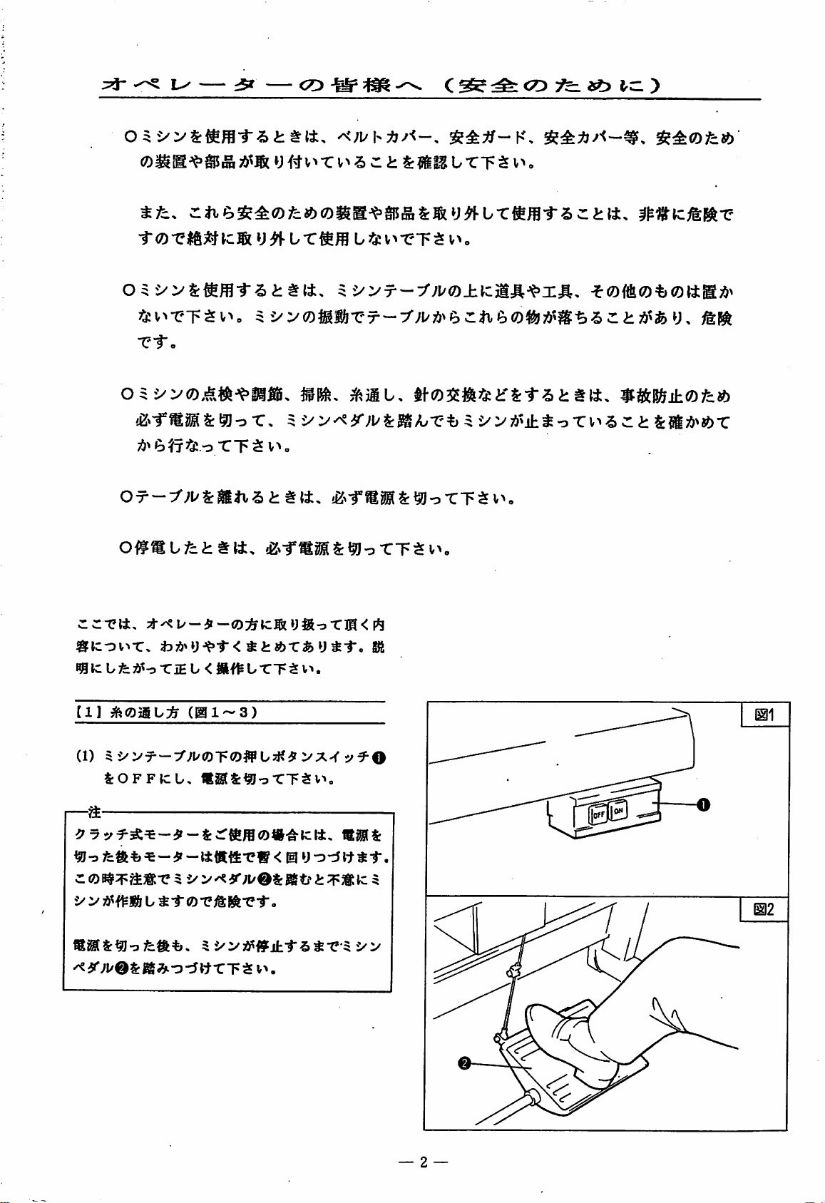
(1)
5i/VT-:'';KJDrOff
SrOFFtcU.
—a
^ o fca % ^ -
d
®
y y WS& u ^"T
^a*';i/0Srg[;^o^[t-CTSv>.
t);i>^y-^-r<^i;«?>Tfey^1-,
(igi~3)
«S&^oTT$V^.
ar - It tttt
^yy^
0T?i&lift-ci"«
-e w <
UsKif
VX'<y^O
HI
y-o-ti
gft
1^1
It i 1".
— 2 —
Page 6
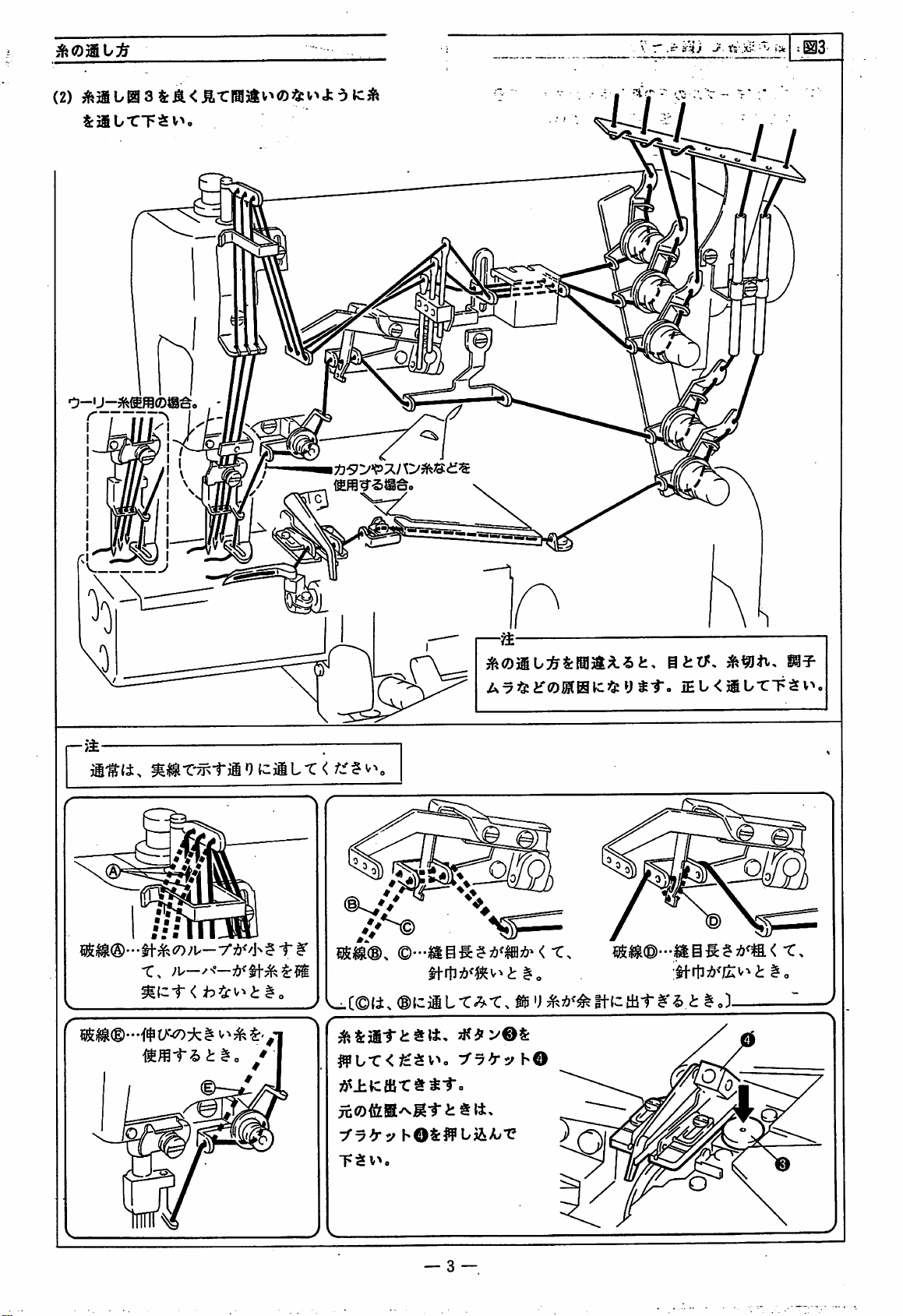
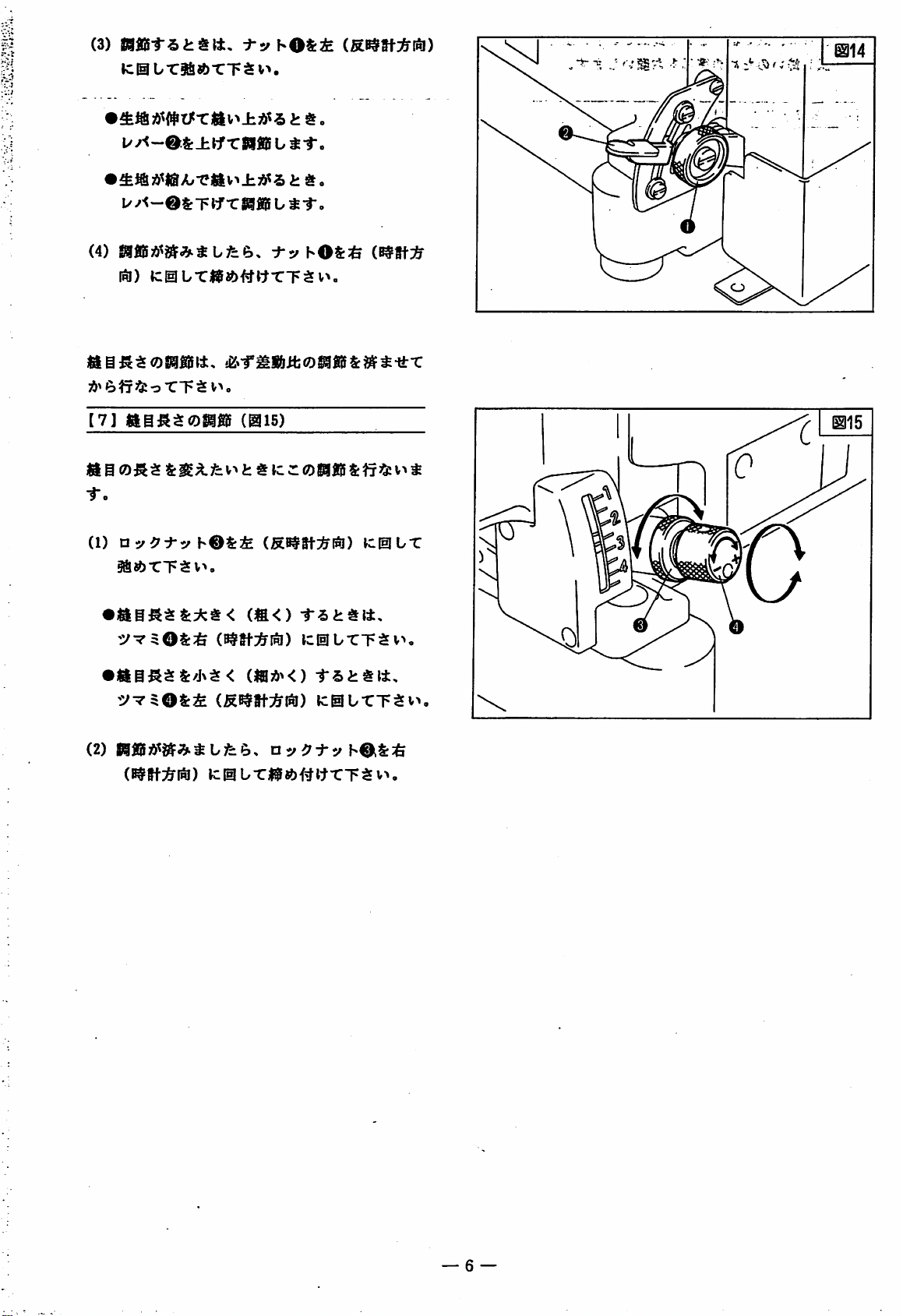
(2)
^3iU03S:A<^-cra^v^®35:v^J:dk:ife
SrjfiUTT^vn
0-ij-
tisypTsny^B-ii^
\ T .i' ifHJ
fv . ,
r»,
J-
Xs
.'Xi-
>;«
—>i'
"N
/"
®^',
//^
K
,C©(±.
#b-C<^:Sv>,
'fyb'v
T;S
v>.
A735:iroMHlC55:y
©•••ass?A'W><
m
:fy^yhO
hOS:?PbjiiAy'C
t-r«
iEb
OUTT^
t.
'J
^s;!f<^if-(ztiit$^'^.t^oX
v>,
-c.
y
V.
— 3 —
Page 7
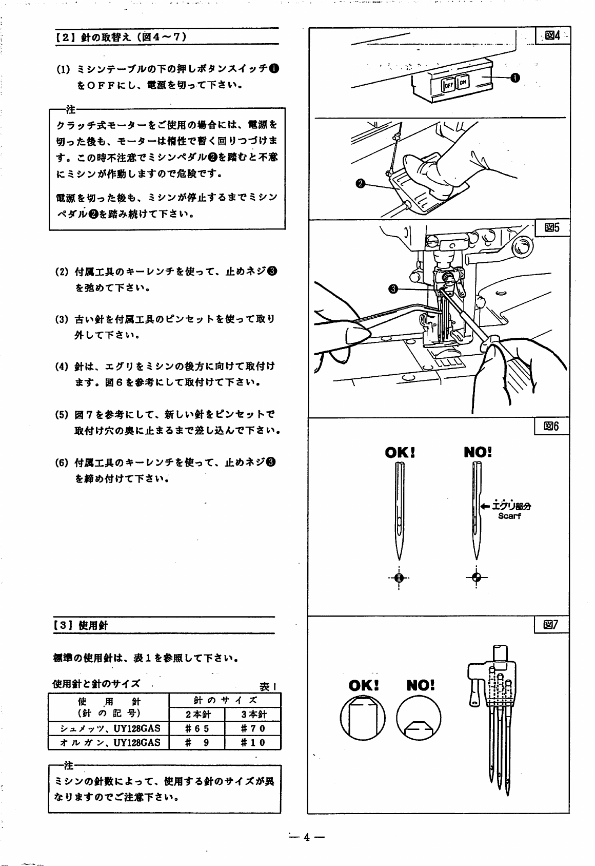
[2]
(1)
5
SrOFFKlU,
(04-7)
yf-O
—^
f.
Cl0^^^j®x5
K^i/>
^
————
U
^-tOX^IiftX-r.
ItTT ^ V^
(2)
&3fi8brT$v^,
(3)
^l^#tS:#jaX:ir®fcrv-fes;
^UTTSv^.
(4)
mt.
0
6Sr#^k:UT®t#itTT5^v>.
i:^3K
o
jhA^t^©
hS:«BoX5(y
(5)
07S:#^JCtT.
(6)
#jaX:ft©=*-UV^Ic^oT,
S:tjfsb{^t^rT^v^.
llfUv^lf^fcrvfey
[3]
(S6fflti-i:tta)-y--fX
^
m ^
m
(n
le
Uyi28GAS
t
fi'
UY128GAS
.
^)
ti-
2
2^^
#6
# 9
(7)
5
-f
3
#70
#10
hX
X
4^:^
OK!
m
NO!
^—;
5
5/vo^«k:J:oT,
55: y t^®Xcr^STS
v^o
— 4 —
Page 8
°4-^n5»BSin?'''ki5ia5^
[^
55^
2?:#
fl
gES©^BS^
::i#^ra;?
%i?5L:i.nJ!S
'¥1$:?9'4-!!S^
(8B)
T
^4-£6S-g^
(^¥45^2^)
W©0:3r^#
(6B)
•4-$
n
q>3^3.
*?H
'iQ!gg?©H'^4
urn
m
^©H
°4-¥«9gvC«^^4.1il-i
•
TiT
t
(i)
5
®/?
4-0
^
'n-iNo?
•
4.
$
n
35:
>
gg
vV
3ff
^
(H~oTgi)
'
fi
'1
(Ti0)
tf
}(2n
#0951©^r/:—:&</?
(OTEI)
•vi^iLaiiY^^a
2m
—
s
—
Page 9
(3)
k:0Ur5a«?)TT$v>.
t^o
t:S!«5 U i
U-®
(4)
iRl)
^raTTS
[7]
1AU^:^(0mm
i(4
0
-r.
(1)
Uy^Xy
gfi««)rT$v>.
S: T T
SgfiB U ^
f.
i-yhO^^
k:gILT)R^^^)f^^^'CT$v^,
V^o
(@15)
Sr^^fe
v>
i: # »c ^ 0®!«f
hOtitE
(S^tf:i^l^)
lcliIbTT$v>,
S:^5^
JCIULT
v>
^
5/T$OS:^
(2)
|g«5;!)^^^-^4bfce.,
C^fft^^lSl)
k:@bTiRf«)#ltrT$v>.
kiBb-CTtEV^
nyi;Xyh^^:^
— 6 —
Page 10
5;
oegM'taSMffiKifeofcJg^fiaSaSiwfiefflTSv^.
cssedkcq fe^
^
■rt,
iAcjKwMHK^isitji^feyif.
0'<;i/h:*j^^-,
• # Jfe
J:*
»c
^1-«
S: S tf S
(S S C
38^40fca)»cai3i55;i»sy0saittttTfey
i a A'^B^S:*«SC66jtt5
O5->V0,^.«^-¥'llfii,
»l^,
iK>-f®8SS:^!Io-C, 5 •>
3^*
6
07-—-fn/i:Mi\'^ttit,
0#(®L/fci:«t±.
o
X~F
■S
V'*«
!2<-f®®(S:MorT3Sv^.
!K>-r«MS:^oTTSin
§Sc:^OfcftoSB-S>Sisatt,
«: S c: t }»< y 11",
;i\
:t^i'—9—
d
ii
K^j: y tl".
#i'0?Siji«Ci:*S:t5.i:«lt,
5
•>
o
Tv^S d t
•
-tLTJSt&aS
*SlitBfejt0fc0
S:Ji!l>0-C
r
CD
ftfcCO
o:5-iSfeiSbt«tt,
V^T?Tc5V^.
O 5 •> V 0 T - X H
isasaxii,
Ti^
1/-o
3l> y t3 % A'O r V ^ 5 d
Ov>o%ttacc^«6fflIM<fc0U:.
stt®«f?fST?d:ai»Tsv..
i: & il
H#0R^,^lftS:effiv''bfr.
0
"C T tS V ■<.
u^c
— 7 —
Page 11
^
^
^
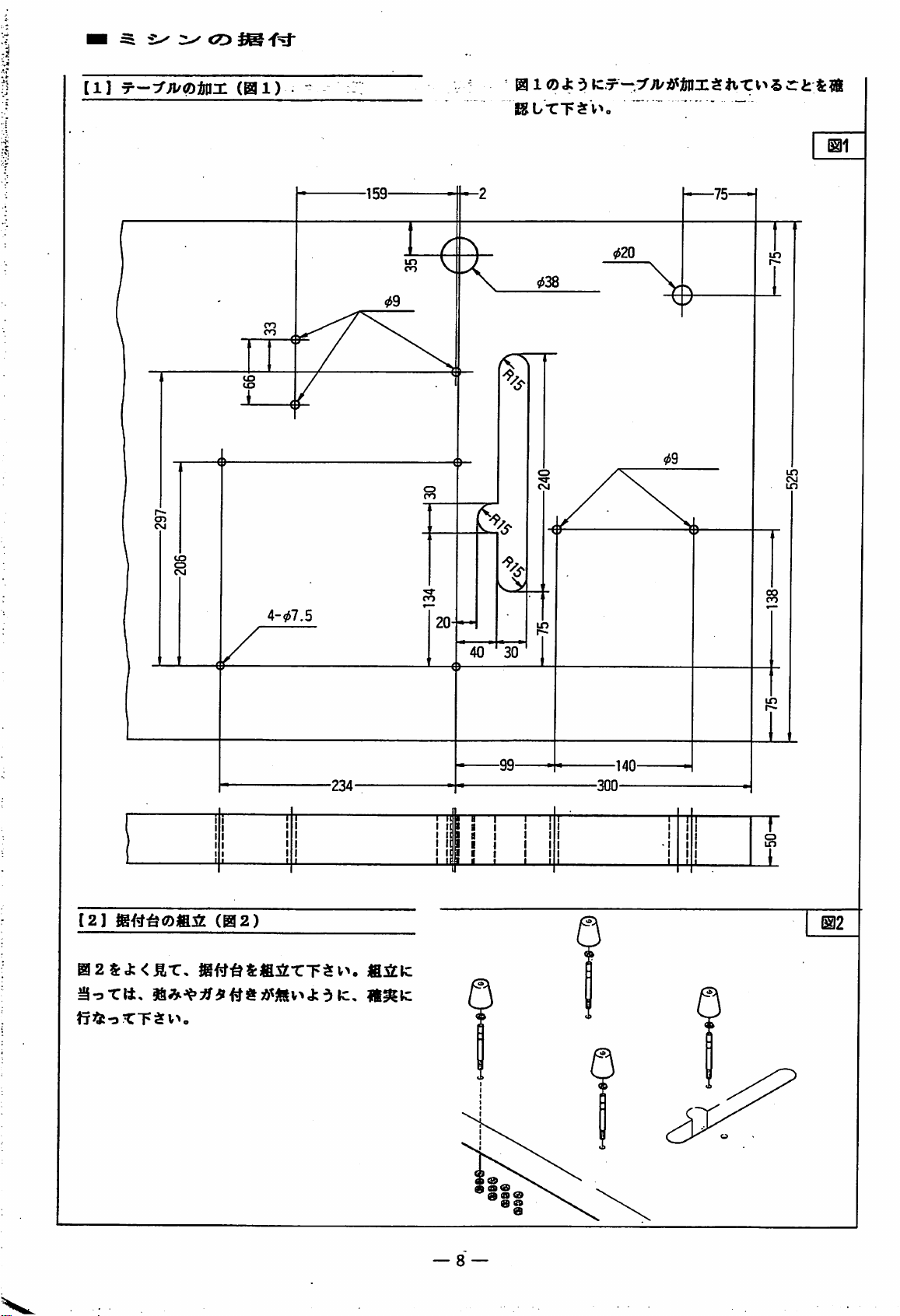
[1]
(01)
01 ® ^ d »c.^-:::^;i/;&^iinx$liTv>s
Vi-
L/X"F
v^o
ri:
&?S
@1
[2]
02&J:<£t,
(02)
4-9J7.5
fi
iCk:
40
30
m
— 8 —
Page 12
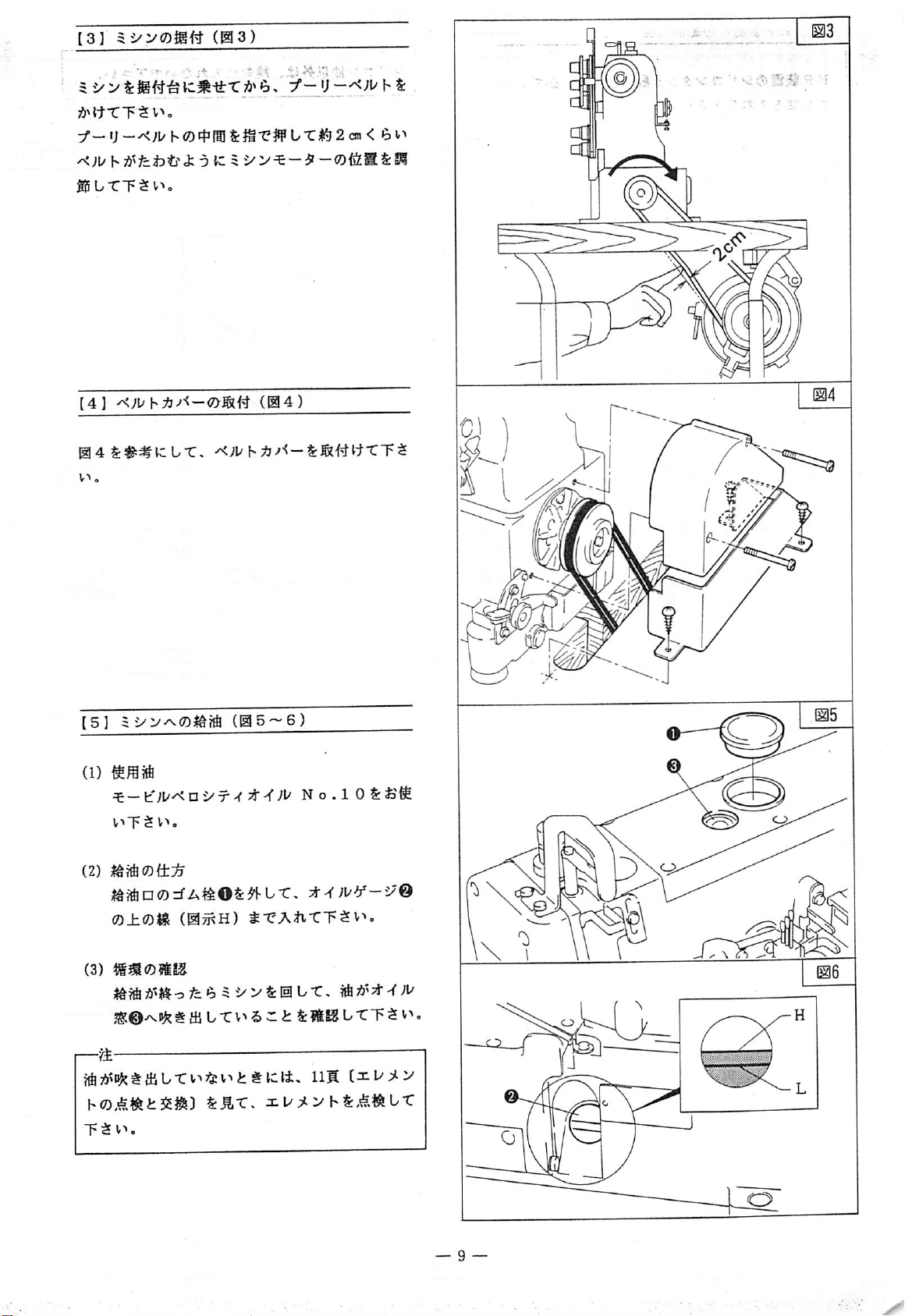
[3]
5
-> V S:
A^ttTT^v^.
y_ij_x;tyf,®cf>raS:J^-e#tTi^^2OT<
(03)
fj'
^
&
e>P
A^fct)tf
liSLTTi^l'''-
[4]
4t##lcUT,
J:
oizi
-©ffiSS:®
B
i
(04)
—
(5]
(1)
^
—t'yi'^n
V^*P
cE
V^
o
(2)
0±<Dm
(3)
JS?fiA»J^ofcei5i/VS:I51U-C,
JS^©^^ t m L T
—^
T$v-»,
(0^H)
(@5'-6)
i'-r
^-eA^-cTSv^,
v^-5 ^ i:
No.lOSriaS^
S:
?I3S
L-CT 5 .
i
Page 13
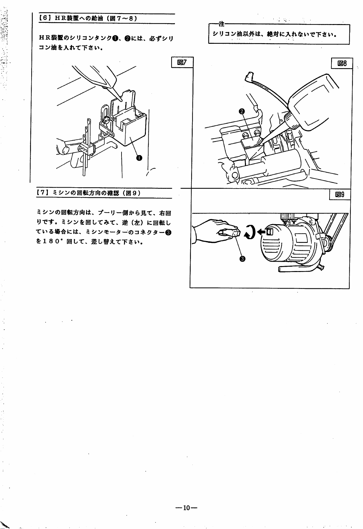
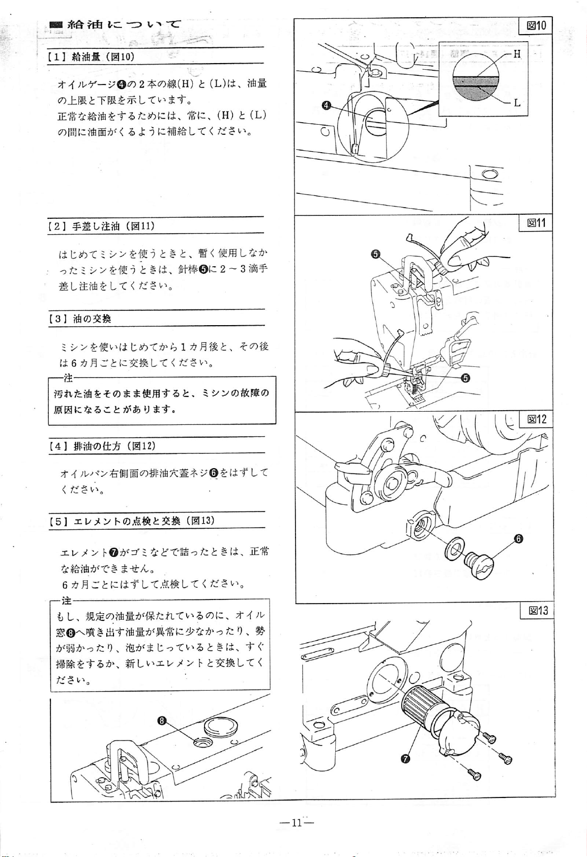
[61
HR^BOJ/U3
3
V?ftl:An-CT$V>.
(07-8)
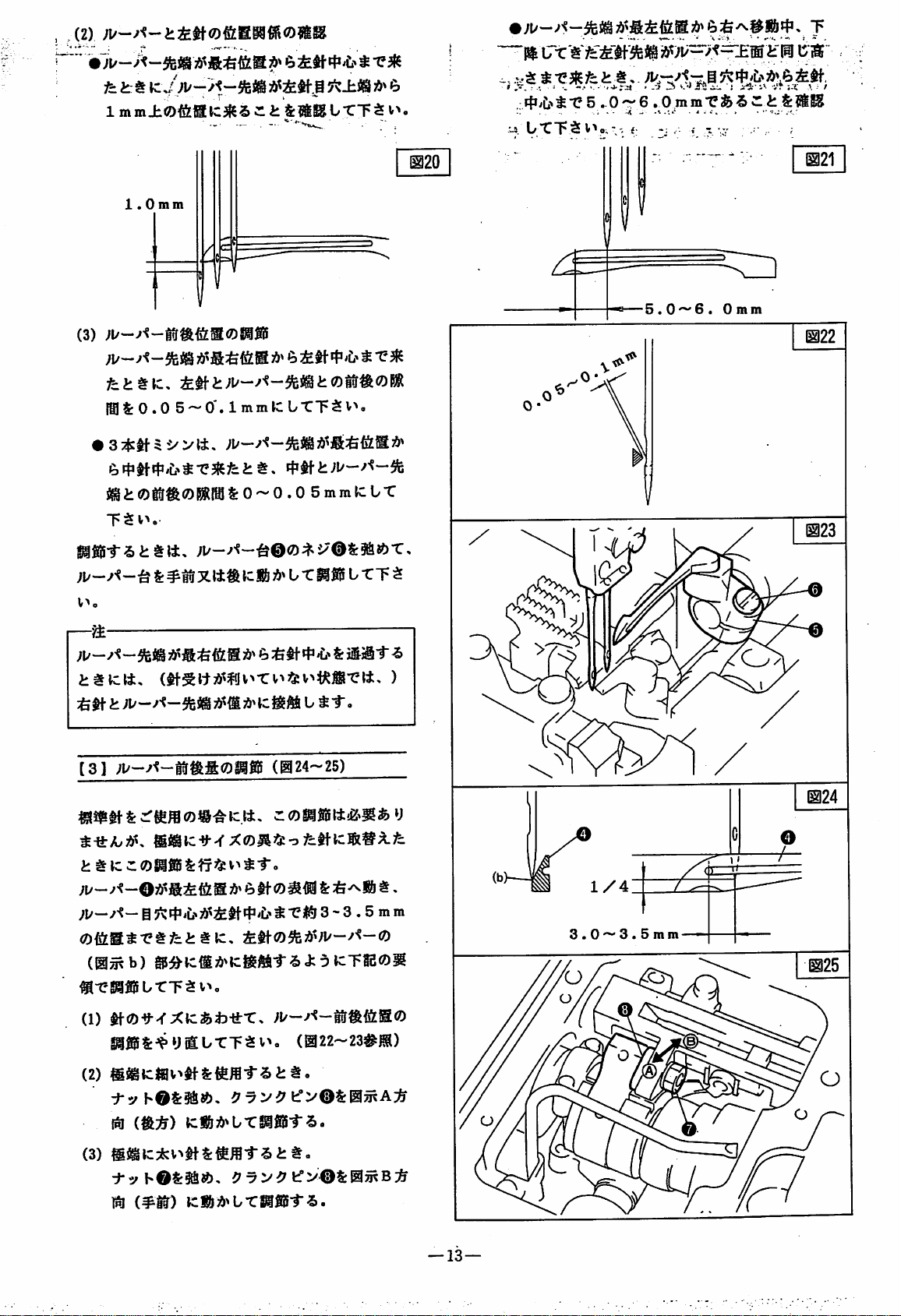
[7]
^^>g)[51fe:)^|^g)jf|Sg
y-c*r,
$:18
0'
@Ur,
^U§^-CT$v>.
(^9)
it
(±)
:&|5I
tcafeu
07
08
09
—
10-
Page 14
[T]
(OTil)
ui
[e)
f)
^^—
iilTc^
z;^
9
^^(om
:r
^
^?¥sli-?
^-1
?
i-1
mm)
^
^
'fKD
?
(H)
(1)
^^£-Zr)0#4#
^
(H)^0?:$:Z0?©i:--^^''i'4^
"4-?
.A
A
$
7;
>
i-n
[t')
>
4^
[9)
w<-
^/'iT
(210)
5.c>q£0^
^
>14-f!^©.^
(STSl)
S3r
I
m
Page 15

wm
wrn^^
J5*
^ ^
[1]
(D^m
(0jRa)
Sk::^SJ:dVc,
(1)
fe
S^"r±lj'TT$v>o
(2)
^rtJ
icj© b fc
(0^b)
(ai4-i7)
^1
Tffi®il^T?Wasu-CT$v>-
CO
tf#©S:±XttTVcS&d^br,
CO
iS $ tSlffli b TT $ v^
&i^^tcSlfflSbTT$v>.
;u®
„
[2]
tf-K:j^'r^;!/w'<~ofeBasiflg
fc
ti-rti
t
ll
3.2n
4.
4.8n
5.6n
6.4n
SISr*
^
2
«
On
ti
a
9.1
n
00
8.6 n 1
l*^
tl
:£tMt^$(a)
lU
8.2 n 1
5.6n
7.4
n
(0^a)
$m.t
^cS5fiiibTT$v^.
l±:fe t ft b r 015 b TT $ v>.
<7)M^
6.4n
(018-23)
^2tci3^f^rfik:iSb
7.8
7.4
n
n
^
o
(o)
<o)
2
fS19
n
3.2n
4.0n
4.8n
5.6n
6.4n
2
m
tl
9l§»a)
4.7'^5.0n
4.3'^4.8n
3.9'^4.2n
3.5'^3.8n
3.1-3.40
tf
5.6n
6.4n
m
9I$S(a)
3.5—3.80
3.1-3.40
—
12—
Page 16
(2)
fe kr^
1
mm±0fe®tC^S
e.
/£? t -e3f5
* k ilSKUTT^
e.
v*.
"~"PI
iTt't
-.
^-e^l^fe
»
.".
.-
■-. = •-
-.•
:4i'C.>11?5
wS.
b'C'F t V'*
11,.
'.
-
.0-6
o, " -.
'
-'•» 3 v.*»
JU
jii. j yS;'
.^PmmrfeSce
<;
-; . 1 T ■
lik
!'•
v.
;-l A ••
/
t
V
1.0mm
(3)
fe
ttle,
laSrO.Q S —
GM
^r|i^f|jii>^-e3f5fett,
"1p $ V*
SIfiJif-St
v>.
^
«■
tli,
S:
^t5Xl±«
mmlCbTTtV^,
0~0.0
lcS& U T
SmmlCbT
®fiji t TT
t
1^20
1^21
r-a
;i/-y<~5feig
:fe$t t ;i/
[31
®iaic-!f-<XO^fe"3fe^tie®i§A.fe
11
ic d 0 ® fflS S:
;i/—
0fitas-etfettle,
(@^b)
^T'S3l5brTtv>,
(1)
@
®^ieM;!»^ieg?tt-rSJ:dieTS50^
Xie^t)-fr-c,
SI®S&^y®b-CTti>«
(2)
@igie«v>^tS:l&ffl-rstto
:fyh©S:5&0,
1^
€)
tf fe V ^
^-f
fe €)
5
ti-0a®
Vi?
KWiii^bxmm^.
-e." & iSiil-^
b ^ "T.
(@24~25)
o
I:
:&^Si
"CIS 3 -3 . 5 m m
;i/—MfitE®
(022-23#®)
f>®S:0^A:;&
^«
3.0 — 3.5mm
(3)
:^2^hOS:§a0,
m
(^IT)
ie«id>bTSifi5i-S.
tr>®%05^B:fe
—
13
—
Page 17
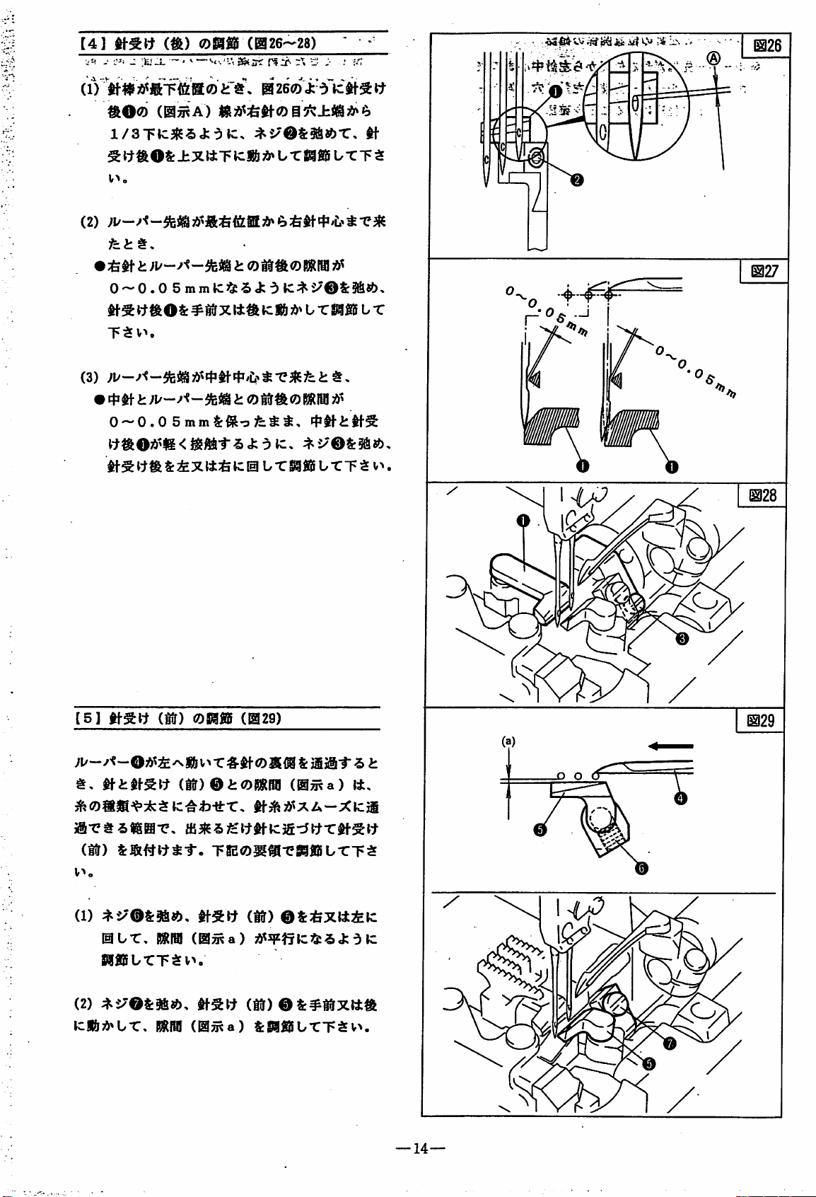
C4]
-•
-:
m
'
v\f
(om
—
■'
^
mzs-zs)
rs:x^
i:
-
;■ ; k;
-
fi
ii^
^ • '
.
®
ao®
m^A)
l/3TtC3f5'5J:'3k:,
^
l:rft
OS:
(2)
±XltT
v>.
•
:6^
i:
;i/
k:«l
?&» b r
i: 0 MSh®
0 ~ 0 . 0 5 m m klJfe S J: d k::^S/OSrSa®.
^OS:
~F $ V'^
0-0.0
#Btf
o
k:S&
;!>> U r
^St^^S:^Xtt:&k:@bTSi«lb-CT5v>.
^
WfilS U T T ^
BRIBI
-4-
®lfi5 U T
[5]
(ttr)
V^o
(1)
:^i^'OS:9a®.
0br.
»l«ibrT3§Jv>,
(2)
^5/'OS:««),
Jc|&;5»br,
(if)
(ir)
RRIBI
RRfB!
®afig
(Bi29)
©i:®RRiai
mma)
T8E®5l«-e8aiJib-CT;S
(le)
©i:feXttik:
(lajRa)
(SiT)
©S:#B?fXtta
(05ta)
S:5afi5bTT$v^.
li,
10
—
14—
Page 18
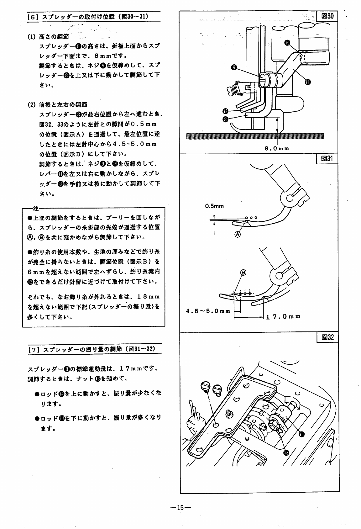
[6]
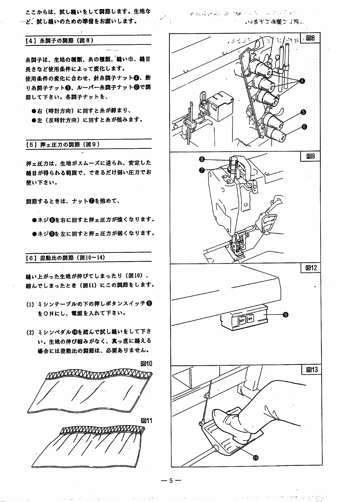
(1)
]®$<oeifi5
x:f
(B30-31)
-
tf|g±©A^6x:f
l/yi''—Tffi^'C,
1/y
i^-®S:±XtiTtcS&;i^
$
V'^
c
(2)
tB^i:fe:&(Z)SSfiiS
©32,
33(2)<fc-5
0&m
(@wA)
bfci;
©feM
(©5^B)
l/y<-<D$:iXli:fe»cSiA^U«7i>e>,
y.3^-®S:
$
vn
•
±g2(3!)SI0SS:-r"5i:^tt,
to.
®,
(DS:^lc5i;0^8?)'5:7!>^e)g®J®bTTSv^,
8mm"e-fo
trS3f®
tcitfilORSraA'O . 5
fe
iijaUT,
4 . 5-5 . 0
icUTTSv^,
»Ci& U T
^fiJS U TT
tTT
mm
mm
0.5mm
8.0mm
K
f<:
1131
6mmS:jg?L3&V^t$H-ei/^-re)b,
®
&t S fc
#<
bt:T$v>-
[7]
•
Dy
•
'lttf-®
i>IS0"eTi2
A:/l/y
-5t$l±,
lC)fi-:5ItT®#
y
<X:f U y
3^-g)^yftCDTO
:^y
h®&5atf>T,
K®S:±tcl&3&^-ri:.
y
tto
□y
K®S:TtC«/>^-rt,
tf»
i;
ii
iSyfid^#<55:V
WTT^
18mm
y fi>
(031-32)
17mm-C-r.
y
v>o
S:
4.5'-'5.0mm
-«-
17
.0
mm
1132
—
15—
Page 19
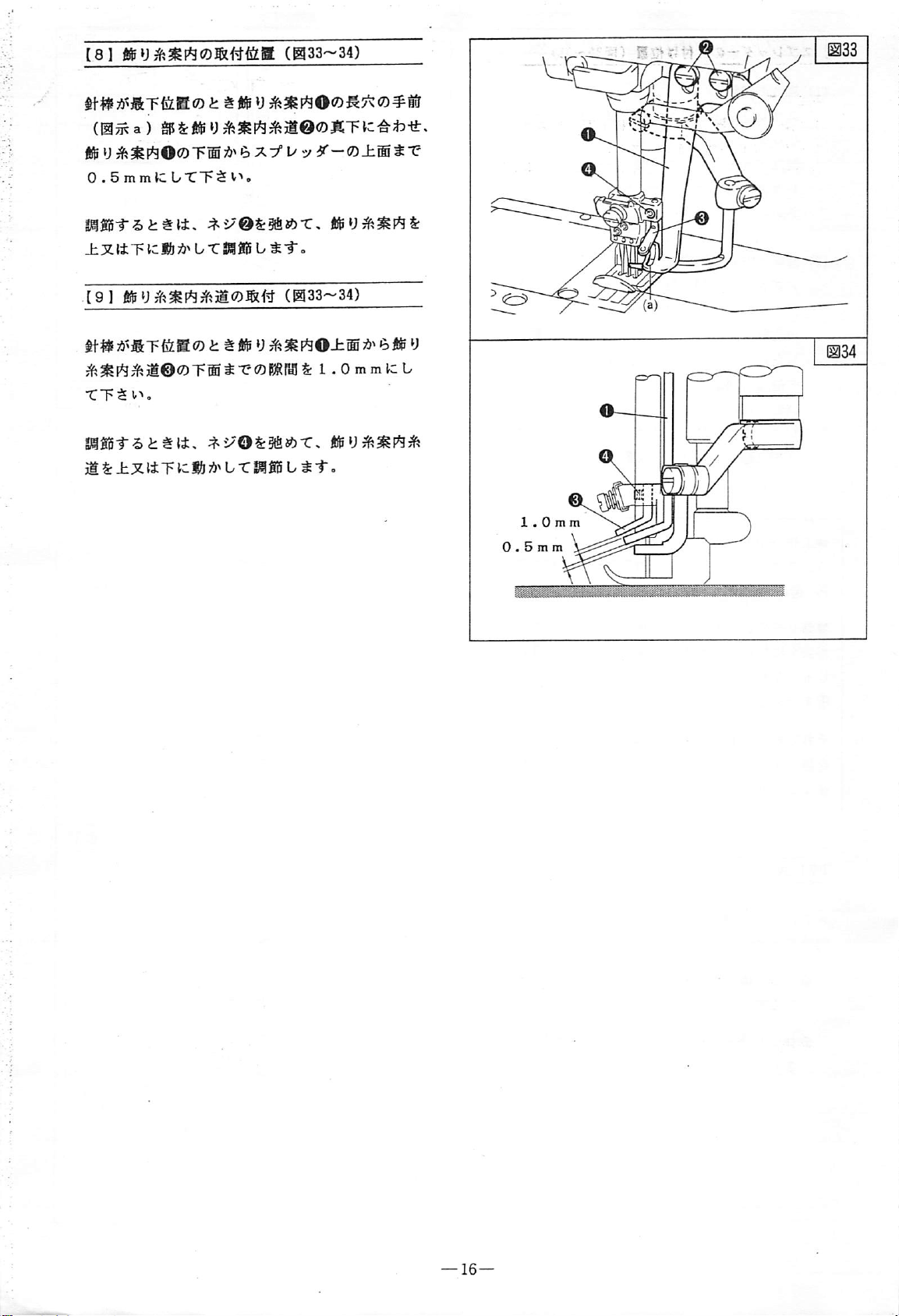
t8l
(0^a)
ftfe U ift^P^OcOT®?!'^
0.5mmlcL/TT$^^o
(033-34)
5/^''"®
Jt®
I ia33
S"e
mJ55-t-5i:ttt.
± X (± T left b T
191
i^i§^[^3^it©0T®tr-CD|®®$: 1 .OmmlCb
TT^v^.
S3®S^-5b^t4,
ig
S:
±X1±T
^2/'@S:5fi8?)T,
S3
«iS b ^-r.
(0
:^i/"OS:§fiJ?)T,
icfii b r
S3g5 b ^ t -
33-34)
4®
U
Page 20

44
W-
8
hr
a;
pa
»
qi
w-
44
*
f
c;
It
0
m
o:
-4
c
4
vZ
■
COcnCO
m
m
o:
41
It
m
IV
0
0>
c:
m
-7i
8
c:
19
IV
rr
IWf
#
(?*•
8
bi
««•
yp
«•
0
nv
It
1^
H
8
4
4
8
3
c
CO
nt-
SI
H
m
r
m
•J
a>
CO
IWr
IV
'
1?
m
ft
c
4
■4
4
8
fW
4
1
CO
^3*
o
"4
CO
H
CP
%
fT
%
4
r
■4
n?r
4
fv
IV
01
a
4
0
4
m
m
vZ
S«
»
41
4-
>4
It
u
-H
Sfi:
9r
up
fl
BD
IV
ff
n
QtB
O'
H-k
<z
m
J>
Ht-
M
o
M*
tsd
r-^
H
m
4-
8
n
95-
It
■
It
0
Sr
ft
?T
A
-4
qi
4-
»
c
M
It
vZ
o
4
03
51^
r\
la
Id
■w
0
m
0
3
O
00
CO
ISl
KSI
It
*
f
<4
rr
??
"4
»
c>
CI
IV
o
5+
r?
bif
O*
n
(VIr
0T
w-
d
pa
Ui
m
}
h-
03
•
K',
4-
»
c
w
A
w*
35
ss
rr
(W(
11^
8
"4
8
o:
>
<-
r\
AV
"4
u',
tt
I
»•
It
Si
<-
e
IW
vS
m
0
w-
d
H
Cl
TIr
4-
£#
<•
0
fW
•
4.
q*
w-
pa
(
(
c:
4
-4
nv
r
H
4
1^
o
Pl>
c:
^
-4
®
S-
SMi'
bj.
41
frt-
<•
bl-
Wr
-rl
oo
CO
CO
>
nf
£h
o
K'.
Swi^
<-
Sf:
B B
B
B
®
9tV
d<
n
(Vfr
1
N,
r
%
®
n
r
d
o
H
Jso
CO
cn
cn
03
rJ
pa
r»
m
e
4*
4
^4
¥
B
o
B
CO
B
cn
B
CO
I
--q
4*
T
e
n
C
gl
GO
H
a;
®
>•
(
e
w-
ri
94*
d«
T
e
(V
-tI
8
>fc
-4
551
8
r?
qi
4&
q:
r\
-tI
5ft
fW
cx
4
Jit
CO
#
o
S
H-*
cn
z:
o
ac
z:
cn
o
tpw
cn
Si
cn
O)
•
«
cn
cn
•
Page 21

[1]
(@40)
lrO.6
•
A-Oamml
icmWVcSilS)
r—
a^$lc<koTtt.
[2]
^S&lbl : 1.3
—
151.3
4.5mm
6^)
O0jt«?)^i^0S:04O<Z)feS
:
1.3
J:y±ic±j&»€)^jci>«ke>
11± 1 :
1.8
(S3fiiS^'
(@41-42)
ilS^#
1:1.3
•
i^i
ic^Pfibt-r.
(1)
ll±-e«effl-rs«-&K:l±.
TS2®gi^T'S!S5brT^fv>o
lii^$fSi®Si'v5O:^S^0(2®)
IfvOOiSS:.
(iS^aS)
UTT^V^o
(2) X Hy^'«-OOjh«)4^i^©S:3fl«)'C,
:&aftcJ:y^l61bS:
3.3mm
SrSfisi),
;&*€) 3 . 2 mmffiS<k O Kl^®i
042©
fea (g3«ib>'<-©®'^v^-7-i7A^0^
1 : 1.8©a^^c-^^ffig)
S:S6;^b-craffl!b-CT$v^-
—B.
d : 1.311T)
5«-&, fcr>o©«i.
(0^ a 0)
brT$v>.
€> 0 . 5 mmiiSS
ais$a®2^^5o
JCXhy^-?-
KMbr^mir
J:
"3
b®
^«!iJt:l.3i'l±
(a)
mwiAmm
KUtt^
(a)
—
18—
Page 22

@43
(11
$:7k¥K:U-CT$v^
®3fi5"r^i:#l±,
h
S:
•
•:f=y>TyV
t-eoWlf!SfeS: 7 SmmtCbrT^V^o
®
S:
•:fe
mm
e ) :^mKWiii'irt,
ijtto
•;&
(05^ © )
—^
t'lx35:
V"*
J:-5
(043)'.. . ■
ten!
brUgBUTT$
(0^a)
ic|&
75^ b r
bTT5
hOff)±m
-fy>Ty
U
Sifi5 b r T $
i:,
v^o
.
(@/Ttb)
v>
o
7
5mm
[2]
#f-jfe^0^giS
^
'>"®0
7 . 0 m m
f^»b>
(^44)
io
IC
bTT 5 V'*o
ji®®
:^i/'®S:5aJ?)T.
&
±X»iT
vC?
17?
SIfiJi-rSiittt,
0
tc|&
75^
b-ClSf® b TT $ v^
S: 0 44(C5tt*
ifiS
®.
tf^ftii®, ® , ® &±XttTJCftA^bTm
bTT^V^o
• ± t
• T U:
[3]
ii
t-2:
if
S)
Ti^-r
i:
if
04§tttc
t)iif T »i{® b TT ^ v^,
if.^^tt0^85
t y ^ t o
(045)
^
t*-
i
tX'O)
tf-i^iai®
„
ic b TT 5 .
®S:§fi«)T,
/
~~
[4] fi(^yjfi^y0^gfi
«&y^«fey®;5»®±fi:aoi:5^,
5^
(05^
c)
;!>»@460<J:e»»c,
B5^0T^C3!$S
y ® S:
±XttT
ic®
(046)
«^y5^^3t®0B
fi
Sy^lfey®®!^
J;
ic
bTTv>.
®&§a«?)-c,
;«)> b rSiSB b TT $ V>,
isyji55«si
—
19
—
Page 23

[5]
@48.
T3fei»yO?!i»fc<'yiiA^'Cv>fe
e. ^ #i 5 J:
gSSSf-Silttt,
IsIUTg3llSL-CT$V'»,
"5
tc U r T S V ^,
:^i^@S:§a«?)-C,
TifeiiyOCa)
[6]
(@47)
1^48
C
3
I
t
TT^
Ifzt^
1^49
-f^fxv
^T?oraPS
v:feif)
^fe<t-CT$v>o
[7]
asi-fik:j®i:-csj®ib^f.
.0,
0&§fl«)"C.
;&»UTS3®fUTT$v>,
•;i/—
S
•
;i/—
ifejiO,
(@5^b)
ifejiO.
v^
o
0C5B5^0fia&«Sc«id»U-CT^
V>o
\Z\tm<
0(D^ni-t
U-CT^v^o
{23{5:ti-5
-fvd-vhO)^^
0®i5^0ffias:##trxtt^tc«i
S:#. < as
©O0j^(3DfitSS^tuSc|&7&^UTT
^
S:
ii>35c < as U fc i:
(@50)
Ufev> ^ #
(@3^o)
t
K\t
S:
—20—
Page 24

■1
[IJ
(@51~52)
-<
a
£9 1 mm
S3 1 m m
@51
;u~y'?-^fej(gAV
@51®
J:
^
|&<fc#®i''r5Vi^<fc
TgB®^M-eMbTT$v>.
(1)
:^5/(D(42t:)
Hlb-Cv
m^'Lzmssbrr^\r>o
•/Nv
KJh>r-;i/S:
^r>r
K^N>r-;i/^
5t>r
5>i^;!^s<:tey^-ro
U)K;lmm^<35cy
S:®®,
(±)
(@w
(@^
V
®®-fey
+
)
-
)
tf-
—;^®S:
httSS:
-|g
1mm
[2]
(@53)
Vif®ISgjSti.
giSSl-'S!:
@bTg®llStTT$V'»o
ttt,
[3]
®3»'<
-^PP
@bT®ifi5b-CT.5v>.
$
(@5^C)
icx#-feV®®'^PP
5
>'^®iia
h®^01
(@3j^B)
&—
(@54)
^i^©S:5fiJ«)-C,
(05^A)
x#-fev®S:
(@5^D)
x#-fev®S:
@53
h®
Sr
if
&
TgSISb-CT^v^,
^1"o
'b
i®
:/3&':^ t <
—21—
Page 25

[4]
(055)
ittOO-^PP
x#-b>00'&®
(0^B)
S:-SS[$-frTT$tv
:^S^®(24c)
-fe V 0S:
[51
t|-0±Tjl8&tc^1'-5#|-^Siy
(05%)
in t TSIfiB
1/r T 5
v>.
(056)
S:6.5mmJCfCT;SEV>o
©5'
m^A)
S:9fi«>T,
-<
x:^
5
\Z
T,
SaiiiL/TT^t^.
—
5S/>0a51^^lCtt.
3feyrir-5#^tt,
ti-OiTjlS&lcfcv^UT,
^^)U-:ft)h}^^ < y
tto
^
—22—
Page 26

ziT
ru«& ■ ^
-M
[1]
MD23
d ; 2
^®
3
1
0
1
rt]i^fe40ffimi
®
8S3 fiiS
^
K-DV^X
-e03*A.
0.9-3T5mmO|gSr\
ait-
^to
'
U'-X
Pi
@57
O
o
e
[2]
[31
|&?a
(1358-59)
[4] 7 y
:7x>i5^©t.
X^^ALT<
ov»T<'-»<i>tv©^{it
x'j-ro,
l&?An^t->*©^(itL-C.
(057)
(B58)
L'C.^t:
.
©~©<7)iii(c
iiac7)irij
<
@58
[5]
^tx®^{ittr.
1SiJc7)A
[6]
d)
l/-X3fefi
(060)
.-e#'6mtMc3£-cf{t-t:^0'ftitr
(B59)
/ux^axLr
(T)
0ft#t^feS08SfflS
<
/::'$v-o
@60
<
—
23—
Page 27

I
im
(H61)
Ua:^
C-"'/vS
V./"»Jf
S52ii
@61
; $
j:
9
,
p-i
r1]
[I]|fxC#v.^TUSA'>f
L
oomm
o
—7—<D(C
<D:^y(
mmi^Os
3'A3^^^
j:-O
KOCy&o-C,
o<Dmm
0-7-©.
5g|^©tO<7)F0ltzJE5i{cAi>^gtc^
'
K<Z>IS®
r)
ztti^J;:iiz^h
t:>
aHO
JE5ilcg6tJ<7)^2;®-.ii»)
.-
-:
L.^-,
Gk
©
Plp1--i)t^(±.
[81
JA^uffluacpgag
3'A^»j^Sc7)^2^6^^iiQ£llLS{±.
\mmit^(Di^ U m
mmx^tto
mm-ti>t^ii.
(+)iig»3iiti>
mcnitt,
-^-
±g2(DS3iii^i:f"e.
^^i>'©.
®l:3lfei6,
(B62)
^-to
LS(7)8i9;
0.9~-2.2min(7)^H-C
.mx'yv^i:^ibx.
mihLmp<§^<^j:n.
^rO
i-To
^F^O,
Tie<7)2
mm^
(-)
—24—
Page 28

'
0
ai
Lfi«;:h4-i;5.;oeHT.
-
@6
l.^^-fe>®c7)it;f.i.'#
^K&$rB^lf-:^f^jc|iIL-C.
(
+
)«(c|5il-i,
i-it-
±seoaiB/^(tT-,
T^toT
<
ai)itiL«i'|t<i:9
Si:
Tie/rvi-gXTjisgBj
(2:45:)
Ill
v>igt)
ifj
LaA<#(,ii
/.',?:::
(_)
n
@65
[9]
^>i/ay0mWi
^IaILT<
tio]
b-;^ir-fK
i'-x;(r-f
m,
$gL*:ass#si;i^i;^
(@65)
X-y
(LG2
10)
i
k:^v>T
~
u.
■ftS!l2:ant5r')i't,5:i^—xS'jii, i jg
X
@66
fill
®9#itT<ir§i,.
Kg)»<i>H
(066)
—
25—
Page 29

F
-=r
T
2
4
•j"-
.-•'.-.i ' -
O
ft 2 4
5^ y «
Oi
U
ffl
5
^ib'it^iro
rii
y
H0<3D?ft5^®l-'
[2]
btt*.
(@67)
(^68)
S:
tTT^Vn
^
1^68
Pif5i"-5
tt
;6
i;
^t±»
:^t;©$:gfi8?)"C#^rtOS:iX
Jcl&7&^
b-CiailS b TT ^ v>,
[31
zfA,
b-x,
If
St,
S:XA-Xlci3|y
^filii-Sttli,
(B^St:;^!^)
[4]
±>^Xg)gfJ^gg
^isaa-c-eiSSfcifSK
tf,
fy
hOS:9fi«?>t:,
nifilbTSlfilibTT^v^-
(^70)
1^69
(@69)
rfA"^#^
^^i/'®«:^
c
bt-r.
tt
,
•
nfiJ^-^V'»iEflS:5fi<'t'S
y
h©S::feK:0brT$V'».
.BiS^-&v>JEfJ
S8lt5f*y
S:S < f
H@S:ilc!5lb-rT$vv
t
S111±,
—
26—
Page 30

[5]
T^:^^:fe:&fegg)Sgai
m
(05^a)
t-r.
It,
TffB^H^-CSIfflJU-CTSv^o
(B71)
.
(1)
i/-®,
®k=fA3fert®0:^i/'®S:3fl8?)-C,
>i
x^
:fex
It
;&
k:
«i b T
(2)
Ji>ixOjE:^jS3f®S:^yiib-CT;SV'»o
[6]
±XX^0g(f!ftfil;^g)^fig
±^x®A^ST&a0i:t,
JC,
±>lX#®0®<tttiS^S:Sil®bSt-,
y-'J-S:®b-C±^X®S:S:
SSfiii b TT
(072)
±^xoifeiS8i:T;i
^
T
^
I
0 . 5 m m
1^72
S:
±XltT
[7]
(1)
(2)
(3)
ICS& b T0fi5 b TT
±XX0.35il
:^i/-®$:^bT,
V>o
jgfbi^±XX®0jS®
■CTSv^o
(072)
☆v>J:;*X®S:^1-bTT$
(0aKb)
Uff
bott-C,
3f-y~S:0b"C±::*X®S:ftTfitSt-bT,
±>ix®5fejSi:T;*x®0Bfi^-^v^Sg$
0>.5mm)
It®
S &
S:5lKbTT5V^o
ssesafis
b-CT S v>
$
o
-
S:±^X^
±:^X-&0
(^
I8J
(1)
T,
^i>T>ix.®&^1-b-CT^v>.
(2)
±>ix^®S::feK:#4tT,
T5V>.
(072)
_hji
X^®&:felCl0F-ti-
3Kbv^T-5i;^®'&
(4)
±T>iX®ratC5feS:Aix,
T^-U-feabT
—
27—
(3)
:7'-U-S:0b"C
Page 31

mm
V
[21
#±tfl/>^'<~0^VV3^.(H73)
■-
-
:.
[11
Rpmm^^(D^iyyi:p^tbrmv
mm)
ic,
[31
n-y-0pj:m:^(Dmm
n
—5-©0ffxiBE:?ji±.
It.
mSS^iyOt::^
V"*,
(B73)
^^bi&?6&b-cT^v>,
V>^0(DiA:^&(2
(m73)
tElbTT^v^.
iclilbTT^
w<
ttc,
izlt.
l/>'"<-©Sr±if-CT$vn
RPilgSr^fflbTiaSI-^.ii^tctt.
[41
^momvMomss
5
5/V
toizLtto
ay
ay
S:«v>Ji«i)-5*2: H b*&33lU fc'l"
t-y
hOimtbr.
KOfeitf-Si:,
KOfeTlf-Si:,
i:
ttt,
S&U
:^y
xkVMlt0<^V^to
(H73)
heSrSfife-C,
U^i-0
U
y
tl".
m/z
0
©
0
—28—
Page 32

'i
-29—
- . • •*. • •• . .
• • ••
.
Page 33

C
1
d 1 di
L'
vJ
»•?'t}
>■••
This
instruction
"anufactured
PEGASUS
refer
This
*
Instruction
personnel
adjustment
is
rh»
the
following
*
You
mounting,
*
You
adjust,
such
to
their
instruction
manual
must
must
be
be
and
manual
as
machine
respective
manual
manual
part
to
provide
and
maintenance
unless
requirements.
capable
adjustment
familiar
maintain
describes
by
PEGASUS.
motors,
includes;
part
for
for
engineers
instruction
machine
operators
information
procedures.
■requiring
you
are
of
using
and
maintenance
with
the
the
machine
special
adequately
safely
procedure
the
sewing
For
those'not
tables or
manuals.
and
service/maintenance
on
the
installation,
expertise
the
tools
of
the
to
safely.
machines
manufactured
legs,
qualified
for
machine.
install,
and
th^ir
by
please
mountino
and
knowledge
and
can
meet
installation,
mount,
t^tL^Srocedurer^'''"
carefully
before
you
get
down
—
31
Page 34

TABLE
OF
CONTENTS
PAGE
I
To
[ 1 3
[ 2 3
[ 3 3
[43
[ 5 3
[ 6 3
[73
Threading
Replacing
Needles
Regulating
Adjusting
Adjusting
Adjusting
To
Personnel
im
Installa-tion
[ 1 3
[23
[33
[ 4 3
[53
[ 6 3
[73
Table
Setup
Installation
Mounting
Lubrication
To
Checking
Operators
Needles
Thread
Presser
Differential
Stitch
All
Fill
Engineers
Preparation
of
Machine
Belt
Oil
the
—
Tention
Foot
Length
Rest
of
Machine
Cover
for
HR
Turning
(Following
Bust
be
observed
"
Pressure
Feed
Ratio
of
board
Machine
-
And
Service
Device
Direction
of
Machine
37~38
-
-
-
34
34
36
36
37
37
38
39
40
40
41
41
41
42
42
for
safety.)-
~
/
Maintenance
■1
Lubx-ica-ticn
[ 1 3
[23
[ 3 3
[ 4 3
[ 5 3
Adjustment:
1
2
3
4
5
6
7
[
8
[
9
[
10
[
11
[
12
Oil
Level
Manual
Oil
To
Oiling
Change
Drain
Checking
Needle
Setting
Adjusting
Height
Position
Adjusting
Adjusting
Setting
Adjusting
Setting
Setting
Adjusting
Adjusting
Adjusting
Position
Position
Thread
—
Oil—
and
Replacing
Setting
Looper
Needle
Needle
Spreader
Feed
Feed
Foot
and
of
Looper
Avoiding
Guard
Guard
of
Spreader-
Stroke
of
Spreader
Guide
Tilt
—
Height
Lift
—
Oil
Filter
Maintenance
Motion"
(Rear)
(Front)
^
—~
Thread
Guide
43
43
43
43
43
44
44~45
45
46
46
47
47
48
48
~
49
49
49
■
Dif
f
[ 1 3 The
[ 2 3
Machines
To
Use
er-entiai
the
Differential
of
Sandard
Feed
Ratio
Specifcation
Feed
Ratio
Range
Use
the
—
32—
Adjustments
Differential
1:1.3
Feed
1:1.8
Ratio-
50
50
Page 35

TABLE
■
NeedXe
Ad3ust:inent:s
1 1 Adjusting
2 ] Adjusting
3 1 Adjusting
4 ] Adjusting
5 ] Adjusting
6 ] Setting
7 ] Setting
■
TXinXne
1 ]
Adjusting
2 ] Adjusting
3 ] Adjusting
4 ] Adjusting
5 ] Adjusting
Looper
Thread
OF
CONTENTS
T'thr'eaci
Needle
Needle
Needle
Spreader
Looper
the
the
Needle
Thread
Thread
Thread
Thread
Thread
Guide O and
Adjustment:
Timing
Timing
Guard
Spreader
Needle
Thread
Takeup^
Guide
Guard
Thread
Takeup
Takeup^
Guard
between
between
(Rear)
Timing
Takeup
Talceup
—
®
Needle
Needle
Timing—
—
Timing
and
and
Looper
and
Looper's
Thr*ead
—
Back
and
GuXde
Forth
Movement
^
PAGE
51
51
51
51
52
52
52
53
53
53
54
54
■
Met:ar*d.ns
1 ] M D 2 3 1 (Metering
2 ] Setting
3 ] Lubrication
4 ] Lubrication
5 1 Lubrication
6 ] Setting
7 ] Setting
Lace
Position
Position
8 1 Adjusting
9 1 Adjusting
10 1 Lace
11 1 Setting
■
Undeir
1 ]
2 1 Adjusting
Guide
Manual
Lace
Oiling
3 1 Adjusting
4 ] Adjusting
5 ] Position
6 ] Adjusting
7 ] Replacing
8 ] Replacing
Device
Guide^
to
clutch
to
Bearings
of
of
Elastic
Tention
(L G 2 1 0)
Feeding.
Guide—
Fabric
—
Fabric
Tilt
Presser
of
the
Upper
Lower
Guide
of
Presser
of
Lower
Knife
Height
Knife
Knife
Device)
Lace
Elastic
Upper
of
Adjustment:
—
Guide
(Lower)
Guides-
Rate^
—
Trimmer
Foot^
Knife^
Holder
Upper
Knife
—
Adjustment
Holdei
——~~~~
C
A/H
H) 2 3
1)
55
~~
~
~~~
~~~~
~~~
~~
;
~
~~
C
I'' T 2
~~~
"""""
~~
4 O )
—
~
—
~
~~
55
56
56~57
58
58
59
"
59
■■
R.
P
( 1 ]
[21
[ 3 1
[ 4 1
Device
Manual
Manual
Adjusting
Adjusting
Oiling
Lever^
Pressure
Feeding
Adjustment
—
of
Roller^
Amount
of
Fabric
——
—
33—
~
~~
~
Page 36

To
Oper-ators
./
r
K t
K..-'
•:
i
:
V-'
,
I • . .
r ; '
Following
*
Be
sure
cover,
the
Do
prevent
*
It
safety
machine.
not
replace
is
dangerous
machine
of
the
machine
*
To
prevent
off
and
pedal
or
*
Turn
*
Be
This
understand
Operate
before
replacing
the
sure
part
properly
must
to
be
fit
observed
such
guard,
these
accidents,
to
table
when
may
an
accident,
the
machine
maintenance,
the
power
to
of
instruction
off
turn
this
as
the
manual
for
device
safety
device
leave
you
cause
tool
operate
them
make
does
needle,
before
power
instructed.
not
provides
for
operating
safety,
or
parts
cover,
or
parts
or
the
to
sure
run
adjusting,
leaving
off
when
for
etc,
for
any
objects
machine.
fall
that
when
cleaning,
the
the
the
brief
this
safety
before
safety
on
The
off
the
the
power
pressing
table,
power
machine.
fails.
and
as
belt
operating
to
the
vibration
table,
is
turned
the
machine
threading
easy-to-
This
and
ing
part
easy-to-understand
Operate
[1]
(1)
Turn
the
supply.
—
Note
In
case a crutch
ill
turning
pedal 0 is
is
dangerous
move
the
stop
of
this
properly
Threading
keep
unexpectedly.
pedal 0 until
after
(Fig.l~3)
OFF
the
machine
on
rotation
off
power
stepped
turning
because
manual
as
instructed.
push
table
button
and
type
motor
by
supply.
on
inadvertently,
the
Keep
the
machine
off
provides
instruction
switch O under
turn
is
inertia
If
machine
on
stepping
power
supply.
the
off
the
used.
after
the
machine
will
comes
brief
operat
power
It
it
on
to
a
—
34—
Page 37

Threading
(2)
Refer to
correctly.
For
woolly
r~—
use
with
threads
Fig.
3,
and
pass
threads
For
use
spun
with
cotton
threads,
etc.
and
r—Note:
Generally,
Dotted
Dotted
pass
lines
line
•When
©•••When
threads
used.
threads
the
catch
the
because
needle
the
as
looper
does
needle
threads
of
too
small
thread
loops.
stretch
are
^
^
*
shown
not
by
continuous
Dotted
When
bracket
its
Inco^rlct
thread
Thread
lines.
lines
(D,
©-When
is
fine
gauge
threading,
©will
original
eject.
position,
threading
breakage,
your
machine
the
stitch
the
needle
length
the
To
push
and
narrow.
press
may
uneven
cause
stitch
correctly.
Dotted
line
button©.
replace
the
it
J.n^
bracket©-
skip
formation-
•When
is
coarse
gauge
The
stitches,
the
stitch
length
and
the
is
wide.
needle
—
35
—
Page 38

[2]
Replacing
(1)
Turn
—
Note
In
case a cruteh
tuLinn''
pedal a if
?» 5 ®
fr
hl
stoD
after^""*^f^
P
after
(2)
Loosen
(accompanied
(3)
Remove
pincette
thf
fMr"ff^^®
fSl
fhffk!
(5)
Refer
into
the
go
by
(6)
Tighten
Needles
OFF
the
"potation
Stepped
because
turning
screw © by
the
old
(accompanied
to
Pig. 7 and
needle
using a pincette.
screw @ by
(Fig.4^7)
push
button
type
motor
by
inertia
on
inadvertently,
the
'^®®P
machine
off
power
using
tool).
needle
tool).
facing
Its
Insert a new
hole
as
using
by
switch O under
'
la
used.
after
'=''®
"lachlne
machine
®"
alien
using
far
alien
will
stepping
comes
supply.
to
key
a
scarf
toward
to
Pig.
needle
a2
It
till
key.
"
It
it
on
a
k
6
r
3]
Needles
The
standard
needle
system
needle
bchmetz
^Jrgan
needle
and
size
system
UY128GAS
UY128GAS
Is
as
shown
#6
# 9
NEEDI
5
In
.E
Table
SIZE
o-needle
laoie
#70
# I 0
1.
1
—36—
OK!
NO!
a
Page 39

by
triaX
on
the,
sewina
J.>^Get
machine
readv
fs
to
be
fabrtc>:.
ad
jus
etc
C;4l
Regulating
Changes
stitch
thread
According
needle
tension,
Use
*
To
*
To
[5]
Presser
possible,
fabric
To
of
length,
tension.
to
thread
nut0,
each
tension
increase
Turn
decrease
Turn
Adjusting
foot
while
and
adjust,
Thread
fabricsV-threads",Jseam
etc;C.
sewing
tension
looper
tension:
the
nut
tension:
the
nut
Presser
pressure
obtain
loosen
r(^tion
require
•'.
conditions,
nutO»
thread
nut
as
follows:
clockwise.
counter-clockwise.
Foot
Pressure
still
should
sufficient
proper
stitch
nut O and
(Fig.8)
width,
re-adjustment
•
adjust
spreader
tension
(Fig.9)
be
as
light
to
feed
formation.
by
thread
nutO.
as
of
e3a
■■f
r>
»•
a.''•f'
«*'«)»rfW
Rg.9
i
*
To
increase
*
To
decrease
[
6]
Adjusting
(Fig.l0'~14)
This
adjustment
fabric
(Fig.
(1)
Turn
the
supply.
(2)
Do
machine
differential
if
without
Turn
Turn
is
11).
ON
machine
trial
the
presser
the
screw 0 clockwise.
presser
the
screw @ counter-clockwise.
Differential
stretched
is
the
push
table
sewing
pedal
straight
stretching
to
0.
feed
foot
foot
Feed
be
made
(Fig.
10)
button
and
turn
by
stepping
The
adjusting
ratio
seaming
or
gathering.
pressure:
pressure:
Ratio
when
or-
switch O under
is
is
the
gathered
on
the
on
the
not
necessary
possible
Rg.12
sewn
power
Rg.10
Rg.11
—37—
Page 40

(3)
To
adjust,
and
loosen
turn
nut O counter-clockwise
it.
,pnlws8
j
^When
, * • ad
*
When
adjust
(4)
After
and
The
stitch
after
[7]
Adjusting
To
change
is
to
(1)
Turn
loosen
_the
fabric
just
to
move
the
fabric
to
move
adjustment,
tighten
length
adjusting
Stitch
the
be
stitch
made.
rock
nut e counter-clockwise
it.
..is
sewn
to
lever O upward.
is
sewn
lever
turn
it.
adjusthient
differential
Length
length,
to
©downward.
nut O clockwise
(Fig.
stretch,
gathered,
must
be
feed
ratio.
15)
this
adjustment
done
and
*
For
longer
clockwise.
*
For
shorter
counter-clockwise.
(2)
After
clockwise
stitch
stitch
adjustment,
and
tighten
length,
turn
length,
turn
rock
it.
turn
nut
knobO
knob
©
O
—
38—
Page 41

To
/Maintenance
AIX
•the
Engineers
Personnei
end
Service
Following
*
Use
specified
power
cause
*
Do
not
safety
Though
operators,
operate
operating
danger
*
To
prevent
the
power
threading
*
Turn
*
Be
the
sure
must
supply
excessive
be
voltage.
replace
guard,
for
the
engineers
the
machine
with
beforehand.
an
turned
or
replacing
power
to
turn
observed
electrical
The
heat
such
safety
sake
or
device
cover,
of
safety
and
abiding
utmost
care
accident,
off
before
the
off
before
the
power
for
safety.
parts
burnout.
use
or
parts
etc.
the
or
components
of
wrong
for
to
prevent
utmost
parts
safety
care
service/maintenance
the
basic
be
will
sure
prevent
that
maintenance,
needle.
leaving
off
when
the
the
power
rules
the
motor
adjusting,
table.
fails.
suitable
or
components
as
belt
accidents.
is
taken,
personnel
on
safety.
operators
is
not
cleaning
for
the
may
cover,
the
should
Thus,
from
the
running
with
0"ttier
*
Should
Do
not
*
Check
the
*
Perform
the
cautions
the
attempt
that
machine.
daily
best
machine
to
the
machine's
routine
possible
fail
disassemble.
to
operate,
grounding
maintenance
condition.
contact
core
procedure
us
is
connected
to
or
our
keep
distributor.
firmly
the
with
machine
in
—
39—
Page 42

Inst
alXat:
JLon
of
Machine
[ 1 ]
Table
Preparation
(Fxg>l)
Check
1.
to
prepare
the
table
as
shown
in
Fig.
Fig.1
[2]
Setup
Assemble
Fig.
2.
assembled
of
Machine
the
rest
Make
sure
securely
4-tii7.5
Rest
board
that
without
board
(Fig.2)
as
illustrated
everything
any
backlash.
is
in
fi ^
I a
I t
Rg.2
—
40—
Page 43

[3]
Installation
Set
the
to
fit
Adjust
that
press
of
[4]
pulley
the
it
the
the
machine
Mounting
machine
tension
can
be
middle
of
on
belt
2cin
of
motor
Belt
Cover
Machine
rest
boardf
on
machine.
of
the
bent
inward
it.
Adjust
to
do
(Fig.4)
(Fig.3)
and
pulley
when
this.
belt
the
be
sure
so
you
position
i
Refer
[5]
(1)
<2)
to
Lubrication
Lubricating
Use
To
fill
Take
into
reaches
(3)
Oil
Be
sure
inside
—
Note
If
oil
[Checking
check
the
Fig.
4,
mount
(Fig.5~6)
Mobil
oil
Velocite
oil
out a stopcock
oil
reservoir
the
upper
circulation
to
window
does
not
and
oil
check
check
e.
'
splash
Replacing
filter.
the
oil
Oand
until
line
that
inside
belt
No.
(H)
oil
Oil
cover,
10.
pour
the
fresh
oil
of
oil
is
splashing
window,
Filter]
oil
level
gauge
m
—
see
and
Page 44

[61
To
Fill
silicon
Fill
the
oil
Oil
for
silicon
always.
HR
Device
reservoirs
Oand 0 with
(Fig.7—8)
Note
Never
oil.
use
any
other
oil
except
for
silicon
[7]
Checking
Machine
The
turning
clockwise^
side.
clockwise
motor
If
),
180°
the
Turning
(Fig.9)
direction
seeing
it
turns
turn
and
reinsert.
Direction
of
the
reverse
the
machine
machine
(counter
connector 0 of
of
pulley
from
is
its
right
machine
Rg.7
Fig.8
Rg.9
—
42
—
Page 45

[1]
Lubrication
Oil
Level
(Fig.
10)
Always
that
H
[2]
Before
time,
than a couple
lubricate
[3]
Change
operation.
6
—
Be
cause
shorten
keep
the
and L of
oil
Manual
starting
or
if
Oil
Change
oil
months.
Note
sure
to
excess
the
oil
Oiling
needle
after
enough
level
gaugeO*
(Fig,
machine
the
machine
of
weeks,
bar
the
After
change
wear
life
oil
in
is
the
between
11)
for
the
is
idle
manually
0.
first 1 month
that,
time
oil
on
change
because
moving
of
the
machine
two
lines
first
for
oil
dirty
parts
machine.
so
more
in
every
;
oil
and
can
[4]
To
Drain
Take
out
oil
from
[5]
Checking
If
oil
lubrication
Check
time
If
restricted
filter © is
and
of
oil
bubbles,
if
necessary,
filter.
Oil
(Fig.12)
screw 0 of
here.
and
Replacing
cannot
clean
the
jet
check
it
regular
in
Window O is
or
weak,
and
replace
drain
clogged,
be
every 6 months
oil
kept.
change.
plug
Oil
Filter
normal
and
abnormally
or
oil
it
contains
oil
filter
with
new
clean
drain
(Fig.
at
the
€
oil
13)
1
Page 46

Adjus'tmen't
[1]
Needle
The
standard
The
needle
between
plate
highest
(1)
the
surface
position.
When
positionr
should
(2)
To
adjustr
needle
needle
needle
Note
After
the
passes
hole
(b)
this
screw
through
in
is
even
Height
setting
height
left
when
the
needle
the
meet
the
loosen
bar e up
bar
height
gauge.
adjustment,
make
the
needle
as
shown
si
Setting
is
is
the
needle
the
needle
bar
mark P on
mark
screw0,
or
down,
corresponding
sure
the
center
plate
in
nd
M
ain't
(Fig.14'^17)
as
shown
distance
point
is
in
A.
prior
that
of
and
Fig.
in
(a)
and
the
bar
is
its
the
highest
handwheel
and
and
adjust
to
tighten
each
needle
the
needle
that the
17.
Table
in
move
to
©nance
1.
needle
the
O
the
the
gap
Needle
2-needle
Needle
gauge
3.2mm
4.0mm
4.
8inm
5.6mm
6.
4mm
[2]
(1)
Height
Left
height
9.1mm
8.6mm
a
.2mm
7.8mm
7.4mm
Setting
Adjusting
Set
to
The
needle
when
position.
To
looper
Position
the
the
needle
distance
centerline
the
adjust,
holder 0 right
needle
(a)
distance
distance
gauge
(a)
looper
loosen
Needle
gauge
5.6mm
6.4mm
of
Looper
(a)
(a)
correctly
as
to
shown
from
the
is
O
screw 0 and
or
Table
3-needle
Left
needle
height
(a)
7.8mm
7.4mra
(Fig.IS'—23)
according
in
the
looper
Table
right
point
right
most
move
left.
1
Fig.18
2.
I
Looper
2-needle
Needle
gauge
3.2mm
4.0mm
4.8mm
5.6mm
6.4mm
Setting
Distance
4.7 — 5.0mm
4.3'-4.6mm
3.9 — 4.2mm
3.5—
3.1 — 3.4mm
3.amm
(a)
Needle
gauge
5.6mm
6.4mm
Table
3-needle
Distance
3.5 — 3.8mra
3.1 — 3.4mm
2
(a)
—44—
.(a)
Rg.l9
Page 47

(2)
.Checking
i~needle,:
*
When
needle
above
(Fig.
the
the
looper
centerline,
the
top
20)
1. 0 mm
position
.—-
point
it
of
the
left
of
looper
is
behind
should
needle
be
and
the
Irom
eye.
left
left
Rg.20
*
When
point
looper
looper
centerline
(Fig.
the
is
blade^
eye
21)
left
flush
center
should
needle
with
the
distance
and
be
comes
the
top
the
left
5.0%6.0mm.
dovm
and
of
the
between
needle
tis
the
(3)
*
To
and
The
in
passes
right
that
[3]
adjust,
Note
Clearance
point
Set
the
needle
0.1mm
the
In
the
needle
the
should
clearance
and
when
left
the
case
looper
centerline,
left
be
needle
loosen
move
looper
right
contact
Adjusting
the
most
the
needle
slightly
right
pisition
needle
Looper
between
the
looper
the
needle
looper
centerline.
of
3-needle
point
0.05*^0.1mm.
and
screw 0 of
holder
and
needle
guard
Avoiding
needle
between
is
behind
the
the
back
the
looper
when
the
centerline
(under
does
and
the
point
point
to
is
machines»
the
clearance
looper
looper
or
forth.
looper
the
condition
not
work).
Motion
looper
left
0.05
behind
middle
between
point
holder
point
point
from
(Fig.
24~
%
when
come
0
25)
5 . 0~
6. 0 mm
Please
may
otherwise
is
When
needles
position
center
centerline
make
needle
touch
manner.
(1)
(2)
note
not
be
fitted.
the
to
of
adjustment
and
each
Re-adjust
according
Fig.
In
case
used:
Loosen
back
rated.
(3)
In
case
used:
Loosen
forth
rated
that
the
necessary
an
extremely
looper
to
looper O goes
the
and
the
looper
is
approximately
the
looper
other
the
to
22
%23.)
an
nut 0 and
in
the
an
nut 0 and
in
the
.
right
extremely
extremely
from
clearance
eye
and
so
that
(b
slightly
looper
the
needle
move
direction
move
direction
avoiding
be
adjusted
different
in
front
its
left
between
left
needle
3.0%3.5mm,
the
top
shown
in
the
avoiding
size.
fine
needle
the
crank
of A as
thick
the
crank
of B as
size
of
the
most
the
of
left
in
Fig.)
following
motion
(Refer
illust
needle
illust
motion
unless
needle
is
pin
0
is
pin
0
3.0 — 3.5mm
to
—
45—
Page 48

[4]
Adjusting
(1)
Adjust
guard
the
when
position.
To
needle
Needle
so
that
(rear)
right
adjust,
the
guard
needle
needle
Guard
the
©is
loosen
(rear) O uP
line
1/3
eye
bar
is
screw © and
(Rear)
below
as
(Fig.26'
(A)
of
the
shown
in
the
down.
needle
top
Fig.
lowest
move
'28)
of
26
(2)
When the
needle
position:
*
The
clearance
and
the
adjust,
(3)
*
guard
When
needle
The
(rear) O back
the
right
(rear) O touch
0'\»
0.05mm
needle
loosen
(rear)
looper
centerline
looper
loosen
between
point
screw e and
looper
centerline:
needle
each
clearance
and
the
or
looper
and
right.
screw
left
point
point
comes
from
right
the
is 0 'v.O.OSmm.
or
forth.
comes
and
the
needle
other
between
point.
turn
needle
the
right
most
right
move
the
needle
needle
middle
guard
slightly
the
right
To
guard
with
adjust,
I
To
[5]
Adjusting
When
the
passes
between
(front) 0 should
still
pass
Adjust
(1)
(2)
behind
the
sufficient
through
in
Loosen
(front) 0 right
clearance
Loosen
(front) 0 back
clearance
Needle
looper O advances
the
needles
it.
the
following
screw©,
(a)
screw©,
(a).
Guard
needles,
and
be
as
to
and
small
the
turn
or
left
be
move
forth
for
(Front)
to
the
the
needle
needle
manner.
needle
in
needle
clearance
guard
as
and
parallel.
and
(Fig.29)
left,
possible
threads
guard
adjust
guard
adjust
the
it
(a)
to
the
—46—
Page 49

[6
]'
Setting
'
1.
2.
• ■
Height:
from
the
S.Omm.
To
adjust,
move
the
Sidewise
should
0.5mm
the
position,
the
needle.
To
0.
in
spreader O reaches
point
adjust,
While
spreader 0 back
sidewise
Position'of
-.V
'
The'height
needle
tighten
Spreader
/ij
of
plate
screw 0 lightly
spreader O up
position:
pass
the
front
the
(B)
lightly
turning
position.
The
point
of
the
hooking
4.5'V'5.0mm
loosen
lever 0 ,
or
forth
(Fig.30^31)
-
,
'
the
spreader
surface
or
hooking
(A)
left
its
point
should
down.
approximately
needle.
left
should
from
the
screws 0 and
move
to
set
O
and
point
When
most
be
left
the
be
at
t E '>'1
i: j T
Ou
6
'j
rLiii)
Note
1.
When
the
where
spreader
2.
If
the
imperfectly
spreader
thickness,
the
spreader
possible
If
the
even
increase
stroke)
making
pulley
the
passes.
spreader
threads
left
not
threader
to
spreader
under
the
not
the
above
and
check
hooking
thread
because
then
shift
exceeding
the
needle
thread
the
above
following
exceeding
adjustment,
the
of
the
points
tip
is
hooked
the
fabric
the
point B to
part
or
S.Omm
guide 0 as
holder.
is
not
adjustment,
(the
18.0mm.
A,
of
the
number
and
set
near
booked
then
spreader
turn
B
of
as
0.5mm
4 . 5~5. 0 mm
8.0mm
Fig.
31
—
1
7.0mm
[7]
The
in
1.
2.
stroke
the
Remove
shift
Loosen
To
To
Adjusting
following
Spreader
of
spreader 0 is
the
arm
cover
.
nut 0 and
decrease
increase
manner.
cover
the
the
Stroke
and
move
rod 0 up
stroke,
stroke,
(Fig,31~32)
17.0mm.
screws
and
or
move
rod 0 up.
move
rod 0 down.
Rg.32
Adjust
down.
■47—
Page 50

[8]
Setting
Guide
Set
the
A
needle
Also,
thread
To
[9]
When
position,
thread
thread
To
part
just
below
bar
set
guide Q and
adjust,
Setting
the
guide O and 0 to
guide
adjust,
Position
(Fig.33"^34)
(a)
the
is
in
the
clearance
loosen
Thread
needle
set
the
should
loosen
of
Spreader
-
of
spreader
eye
of
the
lowest
between
spreader
screws
Guide
bar
clearance
screw
(Fig.33"^34)
is
in
face
O-
guide @ when
0.
Thread
th^ad
position.
spreader
to
0.5mm.
the
lowest
between
1.0mm.
forwards.
guide
the
spreader
The
eye
of
1.0mm
0.5mm
Page 51

[10]
Adjusting
When
-the
position,
straight
feed
dog
parallel
To
adjust,
of
differential
[11]
Adjusting
When
the
position,
line
(a)
and
differential
To
adjust,
the
feed
Feed
Tilt
(Fig.35~37)"'* ' "
feed
dogs
the
line
and
with
loosen
Feed
feed
set
across
loosen
rise
standard
(a)
angle
across
differential
the
needle
screw 0 and
feed
dog
Height
dogs
rise
the
height
the
tips
feed
dog 0 to
screws
dogs 0 and 0 up
to
the
highest
is
tips
feed
top
that
of
dog 0 is
the
plate
move
up
or
down.
(Fig.36~37)
to
the
of
of
0and0,
or
highest
the
main
0.8
down.
straight
feed
and
the
main
surface.
the
tip
dog
0
1.0mm.
move
0.8~1.0mm
[12]
The
When
lift
foot
To
adjust:
(1)
(2)
(3)
Presser
Machine
standard
Turn
to
Loosen
clockwise.)
Lower
to
In
so
this
Adjusting
the
is
and
their
Foot
setting
presser
the
distance
the
needle
the
pulley
lowest
nut 0 and
lever
the
correct
the
above
that
its
position
Foot
Lift
type
W664-01
W644-01
Lift
(Fig.38'-^39)
is
foot 0 is
(b)
plate.
and
position.
tighten
0and
raise
height
condition,
head
touches
with
nut
Presser
2-needle
5.
8mm
6.3mm
as
shown
raised,
between
lower
presser
for
adjust
0.
in
the
the
Screwi
your
lever
foot
3-needle
Table
the
foot
presser
feed
dogs
(Turn
foot
machine.
screw
0.
Lock
Table
lift
5.0mm
6.
3mm
3.
0
0
3
W664-05
W644-05
5.4mm
6.3mm
4.5rom
6.3mm
—49—
Page 52

[
Dd-f
11
ntial
The
Machines
the
Differential
of
Feed
Sandard
Feed
Specifcation
Ratio
Ratio
Use
(Fig.40)
Addustment;^^,;rj^^^
1^0
lsO.6
*
This
range
limited
inch).
Do
not
shown
is
factory-set
shown
Note
Depending
differential
may
damaged.
[2]
To
to
move
in
Fig.
in
Fig.
cause
Use
the
the
the
the
1:1.3 - 1:1.8
-
lrl-3
represents
4.5mm
(or 6 stitches
the
stopperO
40.
(The
to
keep
40.)
stitch
feed
feed
adjustment
the
length,
ratio
dog
to
Differential
(Fig.41-42)
stitch
from
the
1:1.3
using
greater
collide
Feed
Ratio
length
per
positi^
lever
line
as
a
than
1:1.3
and
Range
Q
be
Some
materials
differential
*
This
represents
to
3.3rom
Adjust
(1)
as
Loosen
length
follows.
pin O is
stitch
(2)
Loosen
stopper O to
mark
on
To
to
1:1.8
Fig.
Note
set
the
position
42.
the
standard
re-adjust
end
is
stitch
0.5mm
length
such
as
feed
(or 8 stitches
two
screws
adjust
3.2mm
length
screw
the
the
adjust
differential
the
(smaller
end
out
adjust
blanket
ratio
the
knob
adjust
of
greater
stitch
so
out
the
on
stopper O to
position
lever
on
the
of
pin O so
the
knob
length
per
on
the
that
bottom
knob
scale
feed
than
bottom
shown
require
than
inch).
stitch
the
shown
to
align
with
as
ratio
1:1.3),
that
of
as
the
1:1.3.
limited
end
of
of
the
as
(a).
move
the
the
shown
back
its
the
(a).
in
Differential
greater
surface
than
feed
1:1.3
ratio
(a)
To
set
feed
standard
the
ratio
differential
back
to
the
—
50—
Page 53

®PNe©dle
Xthreacd
Xalceup
Xhiread
[ 1 ]
Adjusting
In
the'
standard
Needle
bracket 0 should
needle
The
^
takeup
To
—
*
bar
distance
and
the
should
adjust,
Note
—
To
tighten
needle
thread
is
between
line
loosen
the
direction.
move
it
in
according
etc.
*
Take
care
the
to
not
takeup 0 from
[2]
Adjusting
Needle
The
distance
and
the eyelet
To
adjust,
thread
thread
guide 0 up
Needle
guide
between
loosen
Thread
settingr
be
in
be
center
horizontal
the
lowest
the
(b)
of
75mm.
screws O and
needle
takeup 0 in
To
loosen
{+)
the
direction.
thread
to
move
its
original
Thread
0
the
should
Screw 0 and
or
down.
GuXcle
Takeup
the
top
Acloust:ment:'s
(Fig.43)
edge
when
the
position.
line
(a)
of
the
needle
Bracket
thread
O.
;
thread,
the
move
the
(-)
needle
thread,
Adjust
characteristics,
spreader
thread
position.
Guide
(Fig.44)
center
be
of
7.0mm.
move
screw
needle
of
7 5 mm
0
Needle
The
and
Fig.
To
needle
To
thread
To
Adjust
istics
[3]
Set
the
To
[4]
The
should
thread
is
To
spreader
thread
distance
the
eyelet
44.
adjust,
loosen
thread
Note
tighten
the
guides
loosen,
this
of
the
move
depending
Adjusting.Needle
needle
center
adjust,
thread
of
loosen
Adjusting
eyelet A of
be
below
takeup 0 as
at
its
adjust,
highest
loosen
thread
guide
between
center
0,
the
should
screws
guides
0»
threads
0,
needle
0r
them
0
downward.
Thread
guard 0 with
its
elongated
screw
Spreader
spreader
the
guide 0 up
Thread
long
shown
position.
Screws
0,
0
center
0,
0,
0
thread,
upward.
on
the
to
be
Guard
hole.
0.
Takeup
thread
eyelet
in
Fig.
0,
0
or
of
be
0,
used.
screw
as
shown
0
up
or
move
,
character
(Fig.45)
screw 0 at
(Fig.46)
guide
of
spreader
46
and
move
down.
and
move
down.
needle
0
when
0
in
it
—
51
—
Page 54

[5]
Adjusting
Looper
looper
needle
1)
2)
To
thread
thread
thread
point
2/3
down
machines.
Level
needle
adjust,
takeup0>
Looper
Thread
takeup O should
at
the
is
in
the
the
looper
(Fig.
with
machines.
loosen
48)
looper's
(Fig.
screws 0 and
Takeup(Fig.47^49)
. - "i
point
(a)
following
for
2-needle
release
lower
edge
49)
when
turn
the
the
position.
for
3-
looper
Rg.47
left
[6]
Setting
Set
the
and
the
the
amount
narrow.
thread,
To
adjust,
looper
Looper.
distance
looper
of
looper
To
decrease
set
to
loosen
thread
guard
Thread
(b)
thread
be
wide.
Guard
between
guard
thread,
the
screws 0 and
O*
the
O*
set
amount
(Fig.47)
bracket
To
increase
to
be
of
looper
move
Rg.48
®
Rg.49
1
[7]
Setting
Align
the
To
the
aligning
adjust,
Note
To
increase
seam,
To
decrease
seam,
Adjust
threctds,
eyes
loosen
move
move
the
stitch
Thread
Guide O and 0 (Fii:.50)
of
thread
mark
on
screws 0 and0.
the
amount
eyes
of
the
amount
eyes
of
setting
length
guides 0 and 0 with
bracket
thread
thread
position
(c).
of
thread
guide0, 0 back.
of
thread
guide0, 0 forth.
according
and
needle
in
the
in
the
gauge.
to
—52—
Page 55

■iTjLin±ne
[ 1 ]
Adjusting
Looper
At
the
the top
As
shown
moves
timing
with
the
to
the
Adjust
(1)
Loosen
and
(upper)
*
To
point
needle,
direction.
*
To
point
needle,
direction.
(Fig.51'-'52)
position
of
left
in
to
Fig.
the
advances
timing
right
in
the
four
shift
advance
moves
turn
retard
moves
turn
Adjustinient:
the
Tinlng
of-approximately
needle
51,
left
when
behind
approximately
when
front
screws
position
timing
to
the
the
timing
the
the
the
of
0,
handwheel
handwheel
in
following
the
the
the
to
betveen
eye;
the
left
looper
left
manner.
turn
of
when
left
when
left
behind
Needle
1mm
looper
needle
Imra
compared
point
needle.
handwheel®
belt
the
behind
in
the
the
looper
in
the
and
above
point
the
gear
looper
left
left
moves
{+)
(-)
1mm
looper
point
1mm
1mm
looper
point
[2]
Adjusting
Looper's
To
adjust
on
the
eccentric
Loosen
adjust.
[3]
Adjusting
The
basic
guard
and
down
made
shaft
To
adjust,
eccentric
the
Back
this
crankshaft
screw
timing,
(D.
>,
Needle
adjustment
(rear)(^avoiding
movement
by
aligning
with
the
mark
loosen
Timing
and
with
turn
Guard
of
of
the
mark
(D)
screw
betveen
Forth
align
the
eccentric
timing
motion
the
on
Movement
the
mark
(Rear)
against
needle
(C)
on
the
and
Needle
(Fig.53)
mark
(B)
and
Timing
of
the
should
the
eccentric
turn
on
crank
the
and
(A)
the
(Fig.
needle
the
be
54)
up
*
When
cotton
that
the
large
touches
loosen
eccentric
shown
that
in
yarn
needle
the
needle
is
thread
needle
thread
screw ® and
®
in
the
the
figure.
used
it
loop
guard
loop.
adjust
direction
might
becomes
(rear)
In
by
moving
of
this
arrow
happen
so
®
case,
—
53—
Page 56

[4]
Adjusting
'xhe
adjustment
left
and
up
and
down
aligning
with
the
To
adjust
and
turn
[
5]
Adjusting
The
adjustment
thread
movement
clearance
crank
6.5mm.
takeup
Spreader
of
right
the
movement
movement
the
mark
mark
the
eccentric
(A)
(B)
on
timing,
©.
Needle
of
the
against
should
between
be
made
collar © (shown
the
Tining
(Fig.55)
timing
against
should
on
the
be
the
eccentric©.
loosen
Thread
Takeup
timing
needle
so
that
needle
of
the
spreader
the
needle
made
upper
two
by
shaft©
screws
©
Timing(Fig.56)
of
the
up
thread
in
needle
and
down
the
takeup
figure)
is
To
adjust
needle
thread
At
it
needle
thread
take
Note
the
is
adjusted
up
Timing
the
thread
without
*
In
case
large
screw © of
and
move
forth.
small.
the
timing,
takeup
up
time
of
and
should
with
it
is
the
when
cotton
needle
the
The
crank
down
not
used.
needle
back
shipment
to
synchronize
movement.
be
extreme
yarn
thread
needle
needle
crank © and
loosen
and
of
altered
elasticity
thread
is
takeup
thread
thread
screw © of
move
forth.
the
machine,
against
except
loop
sued,
takeup
loop
or
becomes
loosen
crank
crank
becomes
needle
when
too
o
—
54
—
Page 57

Met:eir±ng
<
M
[ 1 ]
MD 2 3.1
The
metering
(width
range
[2]
up
to
is
0.9'V'3.5ram
Setting
3
(Metering
device
40mm)
Lace
accurately.
Guide
Device
i
)-
Device)
feeds
per
elastic
stitch.
(Fig.57)
Adaus-tmen-t'Tg
0
or
The
lace
feeding
O
0
Refer
lace
[3]
The
device
keep
[4]
Align
on
Remove
Remove
is
[5]
To
0
can
to
Fig.
Guide 0 (0'V'0in
Lubrication
clutches
come
them
Lubrication
the
sleeve o with
cap
screw 0 and
full
with
Lubrication
lubricate
and
insert
be
checked
57.
Remove
(Fig.58~59)
and
bearings
pre-filled
full
with
to
clutch
mark A on
the
screw 0 and
grease
the
or
to
Bearings
bearings,
grease.
through
screw 0 and
sequence).
of
with
grease.
the
grease.
(Fig.58)
crank 0 and
mark A on
insert
check
not.
the
whether
(Fig.59)
remove
The
amount
the
hole
metering
the
mark
plate
0.
grease.
the
cap
of
B.
fit
Always
A
clutch
screw
grease
[6]
Setting
(Fig.
Set
lace
possible
spreader.
To
adjust,
Position
60)
guide
to
the
loosen
of
Lace
Guide
(lower) 0 as
needle
but
not
screw 0 and
(Lover)
close
touching
turn
as
the
stopper
—55—
Page 58

[7]
Setting
Set
the
according
(1)
Guide O on
Set
under
position.
To
Position
positions
to
guide O so
the
adjust,
guide O sidewise.
(2)
Guides
Set
guides 0 and O in
o«
To
adjust,
move
guides 0 and o sidewise.
(3)
Guides 0 and
Set
guides 0 and 0 so
runs
into
line.
To
adjust,
move
guides 0 and 0 sidewise.
of
of
the
width
the
presser
loosen
and
O
loosen
EXastia
the
or
presser
that
foot
screw 9 and
screws 0 and
Guides
elastic
elastic.
foot
elastic
in
the
line
A
(Fig.61)
guides
is
fed
correct
move
with
guide
A
0,
and
0
that
elastic
guides 0 and 0 in a straight
loosen
screws ® and
0,
and
Fig
0
[8]
Adjusting
Two
settings
device.
One
is
standard
(1)
Standard
On
the
range
To
adjust,
adjusting
To
increase
0.
To
increase
0
in
To
decrease
0
in
Note
If
suitable
obtained
above,
"Adjusting
are
setting
standard
is
0.9
the
the
by
make
Tension"
Elastic
loosen
screw
(+)
(-)
feeding
only
adjustment
Feeding
available
and
the
setting,
2.2mm
wing
0.
the
feeding
the
feeding
direction.
the
feeding
direction.
amount
the
adjustment
on
Rate
for
this
other
per
according
Page
is
the
stitch.
nut 0 and
rate,
rate,
rate,
cannot
25
(Fig.62)
metering
special.
feeding
turn
turn
screw
turn
screw
turn
screw
be
mentioned
to
too.
—
56—
Page 59

(2)
. On
1.
Special
.the
range
To
special
is
change
Loosen
setting
special
1.4-3.5mm
the
setting.
two
set
setting,
per
standard
screws
the
feeding
stitch.
setting
of
eccentric®.
to
the
2.
Insert a key
screws®,
still,
it
3.
Loosen
screw®.
To
the
To
decrease
the
Note
If
suitable
obtained
above,
"Adjusting
[9]
Adjusting
To
adjust,
screw®.
For
more
For
less
while
turn
stops.
Tighten
wing
increase
(+)
direction.
(-)
direction.
feeding
by
only
make
adjustment
Tension"
Tention
loosen
feeding,
feeding,
wrench
into
keeping
handwheel
screws®.
nut ® and
the
feeding
the
feeding
amount
the
adjustment
according
listed
(Fig.65)
nut
®and
decrease
increase
either
eccentric®
®clockwise
turn
adjusting
rate,
rate,
cannot
below
turn
the tension.
the
turn ® in
turn ® in
be
mentioned
to
too.
adjusting
tension.
of
A
until
m
[10]
Lace
The
lace
lace.
ly,
pass
If
the
less
guide
[11]
Setting
Remove
®
in
Guide
guide
If
it
lace
the
lace
through
is
pins.
Lace
(LG 2 1
helps
easy-to
Guide
screws ® and
sequence.
0)
to
tends
many
flow,
(Fig.66)
set
the
control
to
flow
guide
pass
lace
the
irregular
pins.
it
guide
flow
through
of
—
57—
Page 60

Under
Adjustment
The
FT240
its
knife
feed
dog
The
knives
sewing
by
neatly.
[1]
so
the
metering
Manual
Fabric
is
an
under
movement
motion.
trim
that
the
together
device,
Oiling
C
F*
fabric
is
synchronized
excess
with the
it
(Fig.67)
-trimmer
T*
21
trimmer
fabric
lace
can
be
sewn
^4 O )
that
with
before
fed
the
Before
operated
been
oil
bracket
[2]
Adjusts
ensures
fabric
of
To
guide o right
[3]
The
this
be
edge
elastic
presser
the
machine
for
idle
inlets 3 of
for a period
0.
Adjusting
the
position
to
trim
edge
fabrics.
adjust,
according
loosen
Adjusting
presser
according
sewn.
of
For
the
can
foot.
the
Fabric
with
first
lower
Guide
knife
of
with
constant
to
screw 0 and
or
left.
Tilt
of
Presser
foot 0 can
to
the
thick
presser
then
elastic,
foot
feed
FT
device
time
or
of
time,
holder
(Fig.68)
fabric
kind
Foot
be
tilted.
elastic
smoothly
tilt
©upwards.
is
after
it
lubricate
O
has
guide O that
distance
or
thickness
move
(Fig.69)
and
under
from
fabric
Adjust
fabric
the
front
The
the
to
To
adjust,
clockwise.
[4]
Adjusting
The
overlapping
knives
sufficient
To
adjust:
*
To
increase
turn
*
To
decrease
turn
loosen
should
to
adjust
adjust
nut O and
Presser
be
feed
the
nut 0 clockwise.
the
nut 0 counter-clockwise.
of
pressure
as
light
fabric.
overlapping
overlapping
turn
Upper
Knife
of
upper
as
possible,
screw
(Fig.70)
and
pressure,
pressure,
0
lower
while
c
—
58—
Page 61

[5]
Position
The
position
determines
Pig.)
(1)
of
Adjust
Remove
bracket®,
guide®.
right.
(2)
Re-adjust
r—
Note:
Re-adjust
the
is
made.
[6]
the
presser
Adjusting
(Fig.72)
of
of
the
the
excess
in
the
screw®of
loosen
Move
the
position
foot
when
the
Lover
trimming
Knife
lower
knife
fabric
following
lower
Holder
holder
position
from
manner.
knife
screws®, ® and®
lower
knife
pressure
of
Lace
the
above
Height
holder
of
Guide ® on
adjustment
of
Upper
(Fig.71)
0
(a
right
holder
left
upper
Knife
shown
needle
of
lace
or
knife.
Holder
in
Set
the
that
lower
the
position.
To
knife®
screw ® and
or
[7]
(1)
(2)
(3)
height
the
overlap
knife ® is
upper
adjust/
knife ® is
turn
to
the
move
down.
Replacing
Upper
Remove screw ® and
Set
new
to
its
®.
the
the
the
upper
edge
pulley
lowest
overlap
that
holder
Turn
®
that
approximately
of
upper
of
knife
upper
knife
approximately
in
the
the
pulley
lowest
position,
upper
knife
Knife
(Fig.72)
old
knife ® with
(b)
is
flat
and
bring
position.
of
0.5mm.
knives
holder ® so
edge
0.5mm
lowest
bring
upper
then
holder ® up
upper
knife
screw ® so
on
upper
upper
Make
is
and
when
loosen
®.
knife
knife
sure
[8]
Replacing
(1)
Loosen
holder ® to
lower
(2)
Shift
right.
lower
cutting
with
screw
screw
Knife
upper
Insert
knife
edge
the
needle
®.
Lover
®,
the
®.
knife
new
holder®.
of
0.5mm
Knife
(Fig.72)
shift
right
upper
and
holder ® to
lower
lower
plate
Be
knife
surface.
needle
surface
plate
knife
remove
old
the
knife ® into
sure
that
is
the
level
Tighten
If
above
re-adjust
holder.
(4)
Insert a piece
knives
sharp.
dimension
the
and
make
height
of
thread
sure
cannot
of
that
be
upper
between
the
obtained,
knife
the
knives
cut
—
59
(3)
Insert a piece
knives
sharp.
—
and
make
of
sure
thread
that
between
the
knives
the
cut
Page 62

[ 1 ]
R
JP
Manual
Device
Oiling
(Fig.73)
AdJList:ment
[2]
Manual
Lever
(Fig.73)
Before
operated
been
the
for
idle
lubricate
[3]
Adjusting
The
spring
possible,
To
adjust:
*
To
increase
turn
To
decrease
turn
adjust
adjust
*
machine
the
for a period
oil
pressure
while
with
RP
first
hole ^ of
Roller © hold
device
time
of
time,
the
Pressure
should
sufficient
the
spring
pressure,
or
after
linkO*
be
as
to
feed
I^nd-
screw Q clockwise.
the
spring
pressure,
screw o counter-clockwise.
is
it
(Fig.73)
light
as
fabric.
has
Shift
the
fabric,
Shift
is
[4]
Makes
amount
To
*
the
performed
Adjusting
an
adjust:
To
adjust
When
be
decreased.
When
be
increased.
*
For
fine
When
be
decreased.
When
be
increased.
lever 0 up
or
does
lever 0 down
using
Fabric
adjustment
is
same
as
roughly,
raise
lower
raise
lower
the
the
adjustment,
the
the
when
not
use
RP
Feeding
so
machine's
loosen
rod
©,
rod
0,
link
Or
link
Or
sets
this
when
device.
Rate
that
feeding
feeding
loosen
feeding
feeding
and
removes
device.
sewing
operation
(Fig.73)
fabric
sewing
nut © and
feeding
amount.
amount
amount
nut 6 and
amount
amount
then
will
will
then
will
will
©
—60—
Page 63

^
""
V-;v;V ' w
V;-
;
.
-
■
r-
.'i*
t".--
-l.
"
j.-'-
WILLCOX&
44SPRIN6W00DDR1V6
SPRINGWOODIND.EST.
BRAINTREE.
telephone:
Telex:
Fax:
lo
il^l^COXB'QIBBS;
4^
SPRINGWOOD
DRIVE.
SPRINGWOOD
INDUSTRIAL
Ltd-
ESTATE.
3RAINTREE
ESSEX
987628
0376
551055
.
0376
CM77YN
GIBBS
ESSEX
551771
LTD.
 Loading...