

Page 1

INSTRUCTIONS
W562>W542
Cat.
No.
9A2030
A
March,
1984
FLATBED
t
iliitZcox
INTERLOCK
First
edition;
o-giBBS
STITCH
issued
MACHINES
in
March,
1984
ujiL.L.cax
cgiBBS
Page 2

INTRODUCTION
This
booklet
operation
should
become
derive
and
be
useful
familiar
the
best
contains
maintenance
to
use
you
with
from
some
of
and
the
it.
notes
the
W500,
should
machine
on
help
and
the
which
you
to
to
FOR
(1)
Make
(2)
Take
Machine
the
(3)
Turn
the
(4)
Turn
power
(5)
Make
when
(6)
Be
sure
you
needles.
SAFETY
sure
care
machine
off
work
off
failure.
sure
you
sure
Motor
thread
Belt
when
Motor
before
Motor
table.
Motor
Motor
clean
to
turn
has
the
Cover
is
properly
you
connect
as
well
as
switching
Switch
or
whenever
Switch
has
completely
inspect
off
the
power
completely
machine
Power
when
on.
in
the
the
machine.
stopped
or
replace
fitted.
Cord
you
check
you
leave
event
stopped
and
make
when
to
of
the
DAILY
Before
(1)
(2)
(3)
(4)
(5)
After
(1)
(2)
(3)
morning
Check
Check
Check
Check
behind
Check
normal.
specified
lubricated
close
Remove
machine.
If
any
it
to
repair.
Be
machine.
MAINTENANCE
start
each
Needle
all
Needles
threading
about
30mm
Presser
the
of
Foot.
oil
jets
Check
level
and
enough.
work
dust
trouble
the
plant
sure
to
place
is
not
are
correctly
is
correct.
of
thread
in
Oil
Sight
oil
is
maintained
the
hand-oiled
and
lint
or
disorder
mechanic
Dust
damaged
set.
chain
Window
parts
deposits
is
found,
for
adjustment
Cover
over
or
bent.
remains
are
at
the
are
on
the
report
or
the
PRECAUTIONS
(1)
Do
not
s.p.m.
for
(2)
Before
or
if
the
couple
moving
(3)
Always
on
Oil
Sight
(4)
Change
weeks.
(5)
Thread
Diagram
run
the
machine
the
first 4 weeks.
starting
of
parts.
keep
the
machine
machine
weeks,
oil
level
Gauge.
oil
at
correctly
on
Page
at
for
is
idle
manually
between
the
end
as
shown
7.
more
than
the
first
for
more
lubricate
the
of
the
in
4,500
time,
than
a
the
two
lines
first
4
Treading
Page 3
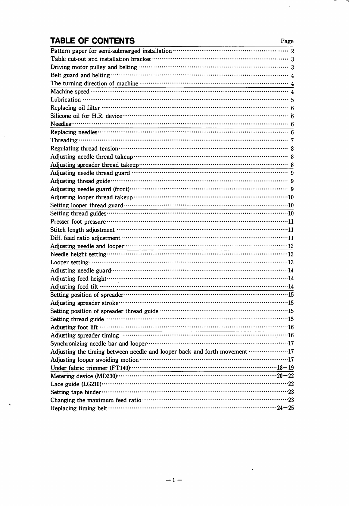
TABLE
Pattern
Table
Driving
Belt
The
Machine
Lubrication
Replacing
Silicone
Needles
Replacing
Threading
Regulating
Adjusting
Adjusting
Adjusting
Adjusting
Adjusting
Adjusting
Setting
Setting
Presser
Stitch
Diff.
Adjusting
Needle
Looper
Adjusting
Adjusting
Adjusting
Setting
Adjusting
Setting
Setting
Adjusting
Adjusting
Synchronizing
Adjusting
Adjusting
Under
Metering
Lace
Setting
Changing
Replacing
OF
paper
cut-out
motor
guard
and
turning
feed
guide
direction
speed
oil
oil
for
needles
thread
needle
spreader
needle
thread
needle
looper
looper
thread
foot
pressure
length
ratio
needle
height
setting
needle
feed
feed
position
spreader
position
thread
foot
spreader
the
looper
fabric
device
(LG210)
tape
binder
the
timing
CONTENTS
for
and
pulley
filter
H.R.
thread
guides
adjustment
adjustment
setting
height
tilt
guide
lift
needle
timing
trimmer
maximum
semi-submerged
installation
and
belting
belting
of
machine
device-
tension
thread
thread
guide
guard
thread
and
guard
takeup
thread
guard
(front)
takeup
guard
looper
takeup
,
of
spreader
stroke
of
spreader
timing
between
avoiding
thread
bar
and
motion
(FT140)
looper
needle
(MD230)
feed
ratio
belt
installation
bracket
guide
and
looper
back
and
forth
movement
Page
2
3
3
4
4
4
5
6
6
6
6
7
8
8
8
9
9
9
10
10
10
11
11
11
12
12
13
14
14
14
15
15
15
15
16
16
17
----n
17
18—19
20—22
22
23
23
24—25
-1
-
Page 4

r-Note:-
•
For a machine
•
For a machine
equipped
equipped
with
with
the
the
under
fabric
needle
positioner,
trimmer
(the
cut
the
FT
device),
portion
d).
cut
the
Rg.1
portion
-2-
Page 5
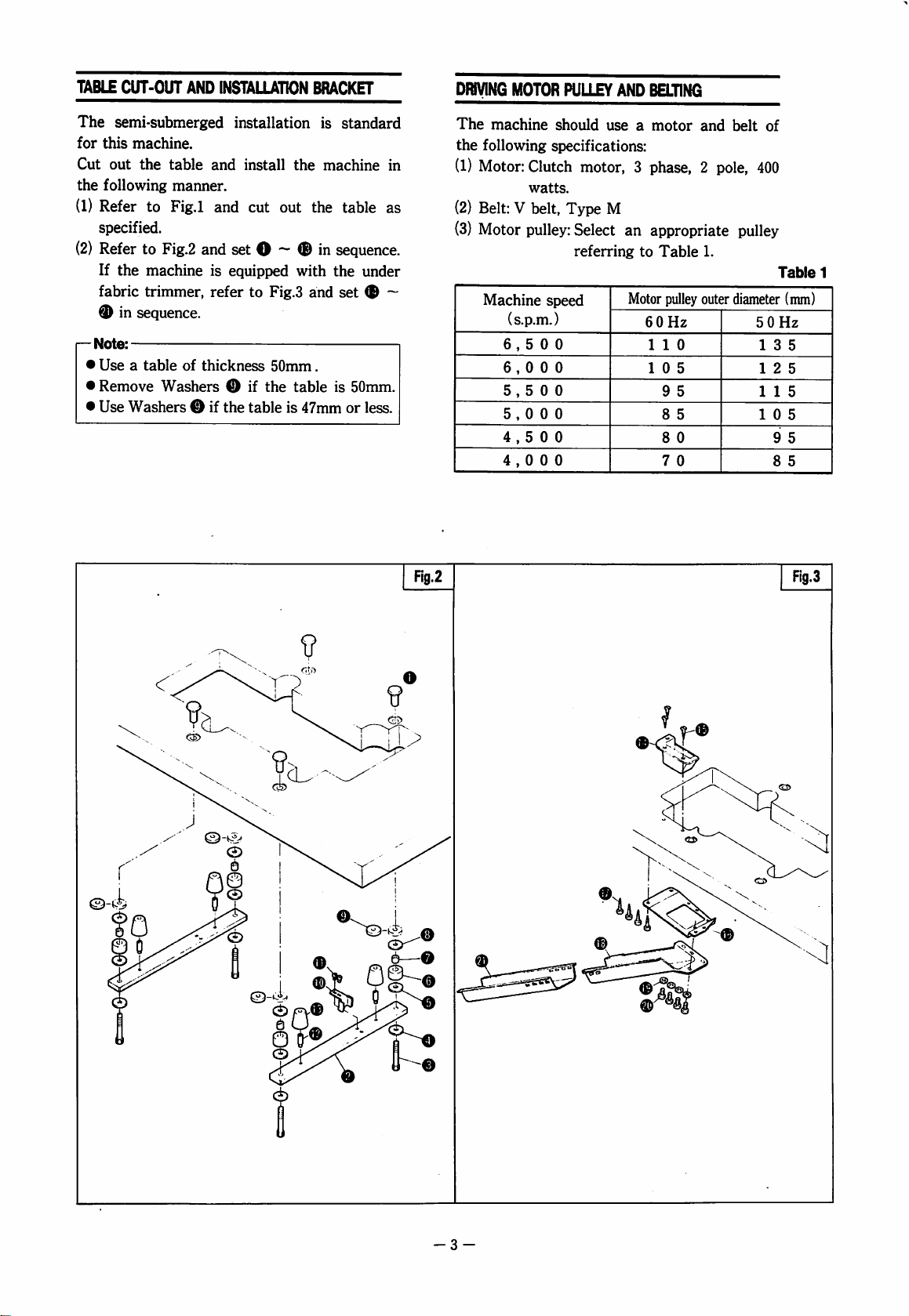
TABLE
CUT-OUT
The
semi-submerged
for
this
machine.
Cut
out
the
the
following
(1)
Refer
to
specified.
(2)
Refer
to
If
the
machine
fabric
r—
Note:
•
•
•
trimmer,
®
in
sequence.
Use a table
Remove
Use
Washers o if
Washers O if
AND
table
and
manner,
Fig.l
Fig.2
and
is
refer
of
thickness
INSTALLATION
BRACKET
installation
install
and
cut
the
out
the
set O ^ ® in
equipped
to
the
table
with
Fig,3
50mm.
the
table
is
47mm
and
is
standard
machine
table
as
sequence.
the
under
set
is
50mm.
or
less.
in
—
DRiyiNG
The
the
(1)
(2)
(3)
MOTOR
machine
following
Motor:
Belt: V belt.
Motor
Clutch
watts.
pulley:
Machine
speed
(s.p.m.)
6,500
6,000
5,500
5,000
4,500
4,000
PULLEY
should
AND
BELTING
use a motor
and
specifications:
motor, 3 phase, 2 pole,
Type
M
Select
referring
an
appropriate
to
Table
1.
Motor
pulley
outer
60
Hz
1 1 0
1 0 5
9
5
8
5
8
0
7
0
belt
of
400
pulley
Table
diameter
50Hz
13
12
1 1 5
10
9
8
(mm)
5
5
5
5
5
1
3
Fig.2
Fig.3
9
C£>
D
-3
-
Page 6

BELT
GUARD
(1)
For
safety,
Screws 0 on
(2)
Adjust
be
2cm
middle
Adjust
AND
be
the
tension
bent
of
it.
the
height
BELTING
sure
to
fit
machine.
of
the
inward
of
the
Belt
Guard O with
belt
when
you
motor
so
that
press
to
do
it
can
this.
the
THE
TURNING
The
turning
clockwise,
side.
MACHINE
Make
Type
maximum
^
Note:
The
maximum
depending
operation,
etc.
DIRECTION
direction
seeing
SPEED
sure
your
Plate O and
speed
as
speed
on
sewing
needle
Select a correct
Table 1 suitable
OF
of
the
machine
machine
run
it
listed
in
may
conditions
size,
thread,
motor
to
your
operation.
MACHINE
Machine
from
type
number
not
exceeding
Table
2.
have
to
be
decreased
such
as
stitch
pulley
size
Pulley
its
right
with
the
fabric,
length,
from
is
MAXIMUM
MACHINE
W562-01
W542-01
W562-02
W542-02
W562-03
W542-03
W562-05
W542-05
W562-06
W542-06
W562-07
W542-07
W562-21
Note:
If
the
SPEED
the
machine
maximum
Number
2-needle
O
O
o
o
o
o
o
o
o
o
o
o
o
is
equipped
-speed
is
of
needles
3-needle
o
o
o
o
o
o
o
o
o
o
o
o
with
5,000
s.p.m.
O
MAXIMUM
the
metering
Fig.5
Table
SPEED
(S.P.M.)
6,000
6,500
6,000
6,000
6,500
6,000
6,000
6,500
6,000
5,500
5,500
6,000
6,5 0 0
6,0 0 0
5,0 0 0
5,0 0 0
5,0
0 0
device,
2
-4
-
Page 7

LUBRICATION
The
oil
was
shipped.
starting
1.
Lubricating
Use
equivalent.
2.
To
Take
oil
level
Sight
3.
Oil
Always
the
Window
4.
Manual
Before
if
the
of
weeks,
So,
it
for
Mobil
fill
oil
out
Screw O and
reaches
Window
level
keep
oil
level
©.
oiling
starting
machine
manually
drained
fill
the
the
first
Oil
Velocite
enough
is
oil
the
upper
©.
Replace
oil
between
machine
is
idle
lubricate
from
the
machine
time.
No.
10
pour
fresh
line
Screw
in
the
two
lines H and L of
for
the
for
more
Needle
machine
with
(ISO
'H'
of
oil
VG22)
oil
until
Oil
when
before
Level
O.
machine
first
time,
so
that
than a couple
Bar
©.
or
the
or
5.
Oil
circulation
Be
sure
Window
(—
If
check
6.
Change
After
-
Be
cause
shorten
7.
Take
8.
If
cannot
months
^
If
restricted
check
replace
o.
Note:
oil
does
Oil
Oil
Change
oil
that,
Note:
sure
excess
To
drain
out
Oil
Filter
Oil
Filter 0 is
be
at
Note:
oil
and
check
to
check
Filter
after
change
to
the
oil
Screw 0 and
that
not
splash
®.
the
oil
change
wear
life
time
first I month
oil
clogged,
kept.
the
jet
it
with
Check
time
of
in
Window O is
or
weak,
clean
Oil
new
oil
is
splashing
inside
Window
in
every 6 months.
because
on
of
the
drain
dirty
moving
machine.
oil
from
nomal
and
clean 0 every
the
regular
abnormally
or
oil
contains
Filter 0 or
Oil
Filter.
if
inside
0>
operation.
oil
can
parts
and
here.
lubrication
6
oil
change.
bubbles,
necessary,
- 5 -
Page 8

REPLACING
Refer
to
Fig.
sequence.
Clean
Oil
with a new
OIL
FILTER
11
and
disassemble O O
Filter O or
one.
if
necessary,
in
replace
it
SILICONE
Keep
silicone
Never
parts.
OIL
FOR
Reservoirs 0 and 0 with
oil
or
equivalent.
use
this
oil
H.R.
DEVICE
to
lubricate
factory
any
supplied
machine
NEEDLES
The
standard
REPLACING
Loosen.
Insert a new
as
the
—
When
insert
Screw O and
it
will
go,
needle
Note:
loosening
the
is
hexagonal
needle
NEEDLES
needle
making
facing
tip
of
hole
of
is
as
replace
into
the
sure
you.
or
tightening
the
alien
Screw
0.
shown
needles.
needle
the
long
key
fully
in
Table
hole
as
groove
Screw
into
far
on
©,
the
3.
-6
NEEDLE
NEEDLE
Schmetz
Organ
Please
note
number
-
of
SYSTEM
SYSTEM
UY128GAS
UY128GAS
that
needles
AND
the
needle
in
the
SIZE
size
machine.
NEEDLE
2-needle
#70
# 1 0
varies
depending
Table
SIZE
3-needle
#75
#
1 1
on
3
the
Page 9

THREADING
Rg.15
Thread
threading
stitches,
your
may
or
uneven
machine
cause
thread
stitch
correctly.
Incorrect
breakage,
formation.
skip
for
stretchy
threads.
I
^
*
for
coarse
stitch
and
seam
width
only.
threading,
come
push
Bracket
out.
threading,
position.
its
for
stretchy
threads.
•for
and
width
fine
stitch
narrow
only.
length
seam
length
wide
(DWhen
Lever o and
O
will
©After
finishing
push
Bracket O into
original
-7
-
Page 10

REGULATING
THREAD
TENSION
Changes
etc.
Adjust
To
To
ADJUSTING
In
©
in
To
The
and
should
f—
Note:
•
•
of
require
individual
increase
Turn
Nut O clockwise.
decrease
Turn
Nut O counter-clockwise.
the
standard
should
the
To
be
lowest
adjust,
distance
the
line
be
87mm.
tighten
Thread
To
loosen
the
(—)
Take
care
threads,
tension:
loosen
Takeup © in
direction.
Takeup © from
seam
width,
re-adjustment
thread
tension:
NEEDLE
setting,
horizontal
position.
Screw
between
(b)
of
the
tension
THREAD
the
when
©.
the
the
needle
To
adjust
needle
thread,
top
line
the
the
not
needle
to
thread,
move
its
original
stitch
of
thread
as
follows:
TAKEUP
edge
of
the
needle
(a)
of
Bracket
thread
loosen
Screws
move
(+)
direction.
move © in
Spreader
Thread
position.
length,
tension.
Bracket
bar
is
©
takeup
©.
Needle
I
87mm
—rr?—N
Fig.l7
/Ctr
T
H
(a)
ADJUSTING
The
eye
(A)
to
the
comer
when
Spreader
highest
To
Thread
position.
adjust,
loosen
Guide © up
SPREADER
of
Thread
of
Spreader
Thread
Screws © and
or
THREAD
TAKEUP
Guide © should
Thread
Takeup
Takeup © is
©,
and
down.
come
in
its
move
©
-8-
Page 11

ADJUSTING
Set
Needle
its
elongated
To
adjust,
NEEDLE
Thread
hole.
loosen
Guard
Screw
THREAD
at
GUARD
the
center
of
ADJUSTING
The
standard
as
shown
To
adjust,
Guide ® up
Note:
To
tighten
To
loosen
Adjust
Lower
threads
THREAD
position
in
Table
loosen
or
down.
the
thread,
the
thread,
according
Thread
are
Guide ® when
used.
GUIDE
of
Thread
4.
Screw ® and
raise
Thread
lower
®.
to
the
type
of
weak
Guide ® is
move
Thread
Guide
thread
used.
synthetic
®.
SETTING
Needle
thread
Looper
thread
Position
of
®
POSITIONS
Polyester
spun
Polyester
spun
Lowest
OF
THREAD
Polyester
spun
Wooly
(G
Lowest
GUIDE
type)
Wooly
(H
Wooly
(G
Center
Table
type)
type)
4
ADJUSTING
As
the
looper
Guard
(Front) ® passes
Set
Needle
to
the
through
To
adjust,
Guard
Guard
needle
the
loosen
(Front) ^ back
NEEDLE
passes
(Front)
but
only
gap
(a)
Screw ® and
GUARD
behind
smoothly.
in
one
and
the
front
(D
as
piece
forth.
(FRONT)
needles.
of
close
of
Needle
the
needles.
as
possible
thread
move
Needle
passes
-9
Flg.21
-
Page 12

ADJUSTING
LOOPER
THREAD
TAKEUP
Looper
looper
needle
1)2/3
2)
To
Thread
thread
point
down
Fig.
23.
level
with
machines.
adjust,
Thread
SETTING
Set
the
Looper
5.0—6.0mm
6.0—7.0mm
To
Thread
adjust,
SETTING
Align
the
the
aligning
To
adjust,
Takeup O should
at
the
point
is
in
the
following
the looper
the
looper's
Fig.
24.
loosen
Takeup
LOOPER
distance
Screws Q and
O.
THREAD
between
Guard O to:
for
2-needle
for
3-needle
loosen
eyes
loosen
Screw
THREAD
of
Thread
mark
on
Screws 0 and
GUIDES ® and
Bracket
(a)
release
when
the
the
left
position.
for
2-needle
lower
edge
Bracket
machines.
machines.
for
turn
GUARD
machines.
3-needle
Looper
and
©.
Q
Guides 0 and O with
0.
0.
3-needle
2-needle
6.0—7.0mm
Fig.23
—Note:
When
the
looper
looper
should
according
gauge.
To
seam,
To
seam,
thread
be
lightly
to
threads,
increase
move 0 and 0 down.
decrease
move 0 and 0 up.
is
at
between
the
amount
the
amount
its
left
dead
Guides 0 and
tensioned.
stitch
length
of
thread
of
thread
point,
Adjust
and
needle
in
in
the
0
this
the
the
1
3-needle
Flg.24
-10-
Page 13

PRESSER
FOOT
PRESSURE
Presser
possible,
and
Loosen
STITCH
While
®
foot
obtain
Nut ® and
pressing
until
Button
while
proper
LENGTH
Turn ® further
Release
•
For a longer
direction.
•
For a shorter
direction.
—
The
approximate
®.
Note:
figures
pressure
still
should
sufficient
stitch
formation.
turn
Screw
ADJUSTMENT
Push
Button
drops
in.
for a desired
stitch
length,
stitch
length,
on
Handwheel
stitch
length.
be
as
to
feed
and
turn
Handwheel
stitch
turn ® in
turn ® in
®
light
as
fabric
adjust.
length.
the
(+)
the
(—)
show
^
rVfAA'
DIFF.
The
Loosen
change
To
stretch
To
gather
r—
Note:
Fig.
setting
•
The
W542-05.
FEED
diff.
feed
Nut
the
the
30
shows
Lever
diff.
feed
RATIO
diff.
the
ADJUSTMENT
ratio
is
move
feed
ratio.
fabric,
fabric,
ratio
move
approximate
is
from
1:0.7
Lever ® up
move
Lever ® upward.
Lever
iB
diff.
feed
1:0.7
to
1:1
to
1:1.3
or
down
downward.
ratio
for
W562-05'
to
by
-11-
Page 14

ADJUSTING
When
the
looper
centerline,
top
of
from
When
is
flush
distance
left
needle
Adjust
the
the
needle
the
left
with
between
in
the
it
left
centerline
NEEDLE
point
should
needle
should
needle
the
following
top
the
AND
is
be
1.2—1.5mm
eye,
be
comes
of
looper
should
manner.
LOOPER
behind
the
and
the
0.1—0.2mm.
down
the
looper
eye
center
be
5.0—6.0mm.
left
needle
above
clearance
and
its
blade,
and
the
point
the
the
5.0—6.0mm
1.2~
Rg.31
1.5mm
Flg.32
Flg.33
NEEDLE
The
standard
The
needle
the
left
surface
when
position.
Raise
the
and
adjust
To
adjust,
0,
and
move
—Note:
•
After
needle
hole
in
is
even.
•
When
the
mark ® on
the
mark
HEIGHT
setting
height
needle
the
needle
the
height
remove
the
this
adjustment,
passes
through
the
needle
Fig.
36.
the
needle
(S).
SETTING
is
as
is
the
point
and
needle
bar
Cap
needle
bar
to
as
shown
Screw
bar
make
the
plate
bar
is
in
the
handwheel
shown
distance
the
in
(a)
the
needle
is
in
highest
in
Table
O,
loosen
up
or
down.
sure
center
of
and
that
its
highest
should
Table
between
plate
the
highest
position
5.
Screw
that
each
the
needle
the
gap
position,
meet
5.
(b)
NEEDLE
Needle
space
2.4mm
3.2mm
4.0mm
4.8mm
5.6mm
6.4mm
HEIGHT
2-needle
Needle
10.2—10.7mm
9.8—10.3mm
9.3—
8.9—
8.5—
8.1—
height
(a)
9.8mm
9.4mm
9.0mm
8.6mm
(a)
Needle
space
4.8mm
5.6mm
6.4mm
3-needle
Needle
8.9—9.4mm
8.5—9.0mm
8.1—8.6mm
Table
height
(a)
5
(a)
/'■'i • •/.'
-12-
Flg.35
Flg.36
Page 15

LOOPER
SETTING
0.9mm
R9.38
The
standard
Make
sure
that
machine.
The
distance
centerline
is
at
in
the
[IISETTING
Refer
to
the
right
following
LOOPER
to
Fig.
mADJUSTING
Set
the
distance
To
adjust,
Holder 0 right
IHGLEARANCE
LOOPER
Set
and
looper
centerline.
To
adjust,
•
In
the
looper
centerline,
0—0.5mm.
POINT
the
clearance
the
looper
point
case
point
loosen
loosen
setting
the
the
(a)
looper
dead
is
setting
is
from
point.
steps.
38
and
set
DISTANCE
(a)
correctly.
Screw O and
or
left.
BETWEEN
between
point
to
is
behind
Screw O and
of
3-needle
is
behind
the
clearance
as
shown
is
correct
the
point
when
Set
the
the
looper.
(a)
Table
NEEDLE
the
0.1—0.2mm
the
turn
machines,
the
middle
in
Table
for
right
the
distance
6.
move
Looper
AND
left
when
left
needle
Screw
when
needle
should
6.
your
needle
looper
(a)
needle
the
0.
the
be
DISTANCE
Needle
space
2.4mm
3.2mm
4.0mm
4.8mm
5.6mm
6.4mm
BETWEEN
2-needle
Distance
4.6—4.9mm
4.2—4.5mm
3.8—4.1mm
3.4—3.7mm
3.0—3.3mm
2.6—2.9mm
25.0mm
(a)
NEEDLE
Needle
space
4.8mm
5.6mm
6.4mm
i-H(a)
AND
LOOPER
3-needle
3.4—3.7mm
3.0—3.3mm
2.6—2.9mm
Table
Distance
(a)
Fig.39
6
1.2—1.5mm
/ Fig.40
Fig.41
"■Q
Fig.42
5.0~6.0mm
-13-
Page 16

ADJUSTING
NEEDLE
GUARD
Needle
clearance
looper
point
that
and
looper
centerline.
1.
2,
ADJUSTING
When
position,
Adjust
on
To
the
Guard O should
between
point
is
behind
the
clearance
the looper
point
Adjust
O
when
Fig.
To
so
that
is
1/3
below
the
43.
adjust,
needle
loosen
Guard O up
To
obtain
loosen
back
the
adjust,
feed
the
Screw © and
and
forth.
the
main
set
the
the
diff.
same
level
loosen
dog
up
is
0—0.05mm
the
point
is
the
the
or
above
FEED
height
feed
or
work
the
right
needle
when
right
needle
between
is 0 —
behind
line
top
is
in
centerline.
the
0.05mm
the
(A)
of
of
the
right
the
lowest
middle
Screw O and
down.
clearances 0 —0.05mm,
move
Needle
HEIGHT
feed
dog
is
in
to
0.8 — 1.0mm.
dog
so
that
as
the
main
feed
Screws O and
down.
so
that
and
the looper
middle
when
Needle
needle
position.
move
Needle
Guard
the
highest
the
point B is
dog
point
©,
and
the
the
Also
needle
the
needle
Guard
eye
O
C.
move
0.1
~0.2mm
ADJUSTING
The
teeth
the
needle
above
the
To
adjust;
1.
Remove
2.
Remove
3.
Open
4.
To
adjust
into
the
[—
Note:
•
The
Set
tighten
•
Make
when
•
Remember
the
feed
FEED
of
the
plate
needle
three
Plug 0 and
Side
Cover 0 and
the
adjusting
feed
tilt
is
Screw 0 to
Screw
sure
that
Screw 0 is
to
tilt
adjustment.
TILT
feed
dogs
should
surface
plate
Screws 0 and
feed
0.
when
surface.
loosen
tilt,
insert a screwdriver
hole
altered
adjust
the
the
shaft
turned.
by
correct
the
remove
and
turning
does
feed
be
level
they
first
Cover
Screw
0.
Screw
turn
Screw
Screw
position
not
slide
height
with
appear
Rg.46
0.8—1.0mm © (p)
0.
0.
®.
0.
and
out
after
-14-
Page 17

SETTING
POSITION
OF
SPREADER
HEIGHT:
needle
SIDEWISE
should
in
front
reaches
should
left
To
1.
Lightly
turning
forth
Screw
i—Note:
After
the
for
2.
Move
height
ADJUSTING
The
plate
surface
POSITION:
pass
the
of
the
its
left
be
at
the
needle.
adjust:
loosen
Lever
to
set
9.
making
handwheel
Spreader
9.
Spreader # up
to
9.2 — 9.7mm.
SPREADER
height
point
left
dead
point
the
the
and
of
the
spreader
should
needle.
be
9.2 — 9.7mm.
The
hooking
(A)
approximately
When
point,
the
hooking
(B)
3.5 — 4.0mm
Screws 9 and
move
Spreader ® back
sidewise
above
check
position.
adjustments,
points
or
down,
Tighten
STROKE
from
the
spreader
from
#.
(A)
and
and
Screw
the
point
0.5mm
point
the
While
and
Tighten
turn
(B)
set
its
0.5mm
1.0mm
9.2~9.7mm
Needle
top
surface
Fig.49
plate
The
stroke
1.
Remove
shift
2.
Loosen
•
To
To
SETTING
Set
the
the
eye
the
between
0.5mm.
SETTING
When
set
the
Cover
Nut © and
decrease
increse
POSITION
part
of
Guide ® when
lowest
Thread
THREAD
the
needle
the
clearance
Guide ® and
The
eye
of
forwards.
of
Spreader
arm
cover
®.
move
the
stroke,
the
stroke,
OF
SPREADER
(a)
of
Thread
position.
Guide ® and
GUIDE
bar
is
between
Thread
Thread
Guide ® to
is
16.0mm.
and
Screws
Rod ® up
move
move
Rod ® down.
Guide 0 just
the
needle
Also,
set
®,
or
down.
Rod ® up.
THREAD
GUIDE
below
bar
the
clearance
Spreader ® to
in
the
lowest
Spreader
position,
Thread
1.0mm.
Guide ® should
and
is
in
face
0.5mm
3.5~4.0mm
16.0mm
-15-
Page 18

ADJUSTING
The
standard
The
foot
presser
presser
To
1.
2.
3.
4.
foot
foot
adjust:
Turn
the
to
their
Loosen
Lower
the
In
that
Lock
Lever o and
correct
the
above
its
this
Machine
W562-01
W542-01
W562-02
W542-02
W562-03
W542-03
W562-05
W542-05
W562-06
W542-06
W562-07
W542-07
FOOT
setting
lift
is
the
and
the
is
raised.
hand
wheel
lowest
position.
Nut © and
height
(a)
condition,
head
touches
position
type
with
UFT
is
as
shown
distance
needle
and
lower
tighten
raise
Presser
for
your
Screw
adjust
Lever
Nut
Presser
2-needle
7 . 0
mm
7 . 0
mm
7 . 0
mm
7 . 0
mm
7 . 0
mm
7 . 0
mm
6 . 0
mm
7 . 0
mm
6 . 0
mm
7 . 0
mm
6 . 0
mm
7 . 0
mm
in
Table
(a)
between
plate
when
the
feed
®.
Foot O to
machine.
Screw © so
O.
©.
foot
3-needle
5 . 0
7 . 0
5 . 0
7 . 0
5 . 0
7 . 0
5 . 0
7 . 0
5 . 0
7 . 0
5 . 0
7 . 0
Table
lift
7.
the
the
dogs
7
mm
mm
mm
mm
mm
mm
mm
mm
mm
mm
mm
mm
ADJUSTING
To
adjust
the
needle
1.
Remove
and
move
2.
Loosen
mark © of
of
the
Tighten
SPREADER
the
timing
bar:
the
arm
Oil
Guard © to
two
Screws
the
eccentric.
Screw
of
cover.
©.
upper
©.
TIMING
Spreader
Remove
one
Position
shaft
with
against
Screws
side.
the
the
©
aligning
mark
®
-16-^
Page 19

SYNCHRONIZING
The
looper
when
The
looper
bar
begins
behind,
at
exactly
To
adjust:
1.
Remove
2.
Loosen 4 Screws
shift
•
To
needle,
•
To
needle,
-
Note:
The
when
Synchronization
the
avoiding
In
this
should
the
needle
should
to
and
then
the
the
the
position
advance
shift
retard
shift
looper
looper
the
needle
motion
case,
holder
may
adjust
rise.
same
arm
the
the
the
the
NEEDLE
be
at
bar
is
in
begin
to
The
return
level.
cover.
®,
turn
of
Upper
in
looper
position
looper
position
is
at
the
bar
is
in
between
change
is
adjusted.
as
above.
BAR
AND
LOOPER
the
right
dead
the
lowest
move
looper
front
as
the
should
of
the
position.
needles
Handwheel ® and
Belt
Gear
timing
in
timing
in
its
the
when
against
the
(+)
against
the
(—)
right
dead
lowest
needle
the
direction.
direction.
position.
bar
looper
point
needle
pass
the
the
point
and
ADJUSTING
AND
LOOPERS
To
adjust
the
mark © on
on
the
ADJUSTING
The
looper
dead
point
needles
motion
1.
Loosen
To
increase
Adjusting
decrease
—Note:
•After
synchronization
looper.
•Please
may
otherwise
is
fitted.
THE
BACK
this
timing,
Eccentric ® with
crankshaft.
LOOPER
goes
and
to
the
right.
according
Nut ® and
the
Screw ® counter-clockwise.
it,
turn ® clockwise.
the
above
If
it
has
note
that
not
be
necessary
an
extremely
TIMING
AND
loosen
AVOIDING
behind
then
Adjust
to
the
the
returns
needle
turn
looper
adjustment,
between
been
the
looper
to
BETWEEN
FORTH
MOVEMENT
Screw O and
the
needles
in
front
the
looper
size.
Adjusting
avoiding
the
changed,
be
different
motion,
check
needle
avoiding
adjusted
size
NEEDLE
align
mark
©
MOTION
to
the
left
of
the
avoiding
Screw
®.
turn
To
the
bar
and
re-adjust.
motion
unless
needle
-17-
Page 20

UNDER
The
continuous
The
feed
The
so
metering
FABRIC
under
knife
dog
knives
that
fabric
type.
movement
motion.
trim
the
together
device,
it
Lubrication
TRIMMER
trimmer
is
synchronized
excess
with
can
fabric
the
be
sewn
(Fn40)
of
the
before
lace
neatly.
W500
fed
is
with
sewing
by
a
the
the
Before
time
time,
Adjusting
Fabric
between
To
Guide O right
Adjusting
The
Adjust
to
edge
can
To
the
machine
or
after
it
oil
Crank
O.
fabric
Guide O ensures a constant
the
fabric
adjust,
loosen
or
presser
presser
be
of
then
adjust,
this
according
sewn.
the
feed
loosen
foot
For
presser
smoothly
is
operated
has
been
idle
guide
edge
and
Screw O and
left.
foot
tilt
on
the
W500-05
to
the
thick
elastic,
foot
upwards.
under
Nut © and
for
the
for a period
distance
the
right
needle.
move
Fabric
can
be
elastic
turn
tilt
the
presser
Screw
and
the
The
fabric
elastic
first
of
tilted.
front
foot.
@.
-18-
Page 21

Replacing
1.
Turn
©
new
i—
Note:
Set
Upper
edge
2.
Turn
©
to
overlap
0.5mm.
3.
Insert a piece
and
upper
the
to
the
upper
Knife © with
(a)
is
flat
the
the
lowest
of
make
knife
handwheel
highest
knife.
on
handwheel
and
position.
Upper
and
position.
the
knives
of
thread
sure
that
the
bring
Upper
Replace
Screw ® so
Knife
Holder
bring
Upper
Make
sure
is
approximately
between
knives
the
cut
sharp.
Knife
with
that
its
©.
Knife
that
knives
a
the
0.5mm
Replacing
1.
Open
remove
2.
Shift
Insert
Holder
Lower
surface.
3.
Insert a piece
and
Position
The
determines
Adjust
and
elastic/lace
To
adjust,
Adjusting
To
move
clockwise.
counter-clockwise.
lower
the
side
Lower
Upper
Lower
®.
Be
Knife
make
sure
of
lower
position
the
this
so
that
the
fabric
neatly.
loosen
Screw
Holder © to
To
Knife
is
of
trimming
knife
cover.
Knife
Loosen
©.
Holder © to
Knife © into
sure
that
the
level
with
the
of
thread
that
knife
Lower
the
is
the
knives
holder
position
excess
sewn
between
Knife
fabric
together
Screws © ©
©.
the
left,
move © to
the
Screw © and
the
right.
Lower
cutting
needle
cut
Knife
edge
the
knives
sharp.
plate
Holder
of
the
knives.
is
trimmed
with
and
turn
Screw
right,
turn
of
©
the
turn
®
©
f—Note:
Re-adjust
the
is
made.
Adjusting
Set
that
the
upper
To
adjust,
Knife
the
presser
foot
the
the
height
the
overlap
knife
loosen
Holder © up
position
height
of
is
of
when
the
of
Upper
of
the
knives
in
the
lowest
Screw © and
or
down.
Knife
above
upper
Knife
is
position.
Guide © on
adjustment
knife
holder
Holder © so
0.5mm
move
when
Fig.
63.
Upper
-19-
Page 22

METERING
The
metering
(width
The
feeding
up
to
DEVICE
40mm)
range
(MD230)
device
feeds
accurately.
is
0.9 — 3.5mm
elastic
or
per
lace
stitch.
Setting
Refer
Lace
Lubrication
The
device
keep
Lubrication
Align
(A)
Remove
Remove
is
Lubrication
lace
to
Fig.
Guide
0(0-0
clutches
come
them
full
the
mark
on
Sleeve 0 with
Cap
Screw 0 and
full
with
grease
guide
67
pre-filled
to
Screw 0 and
to
Remove
in
and
bearings
with
grease.
clutch
(A)
on
the
check
or
not.
bearings
Screw O and
sequence).
of
the
with
grease.
Crank 0 and
mark
(A)
on
insert
the
whether
fit
metering
Always
the
mark
Plate
0.
grease.
the
clutch
To
lubricate
and
insert
The
amount
the
hole
B.
Setting
Set
to
To
iace
Lace
Guide
the
needle
adjust,
the
bearings,
grease.
of
grease
guide
(Lower) 0 as
but
not
loosen
Screw 0 and
remove
can
be
(lower)
touching
Cap
Screw
checked
close
turn
through
as
possible
the
spreader.
Stopper
0
0.
0^
V.
-20-
Page 23

Setting
Set
to
positions
the
positions
the
width
or
of
elastic
of
the
elastic.
guides
elastic
guides
according
dlGuide
9
HlGuides 0 and
HlGuides ® and
on
the
presser
Set
Guide 9 so
presser
To
foot
adjust,
sidewise.
that
in
the
loosen
Screw ^ and
correct
®
Set
Guides ® and ® in
To
adjust,
move
loosen
Guides 9 and ® sidewise.
Screws ® and and
®
Set
Guides ® and
foot
elastic
position.
line
so
that
Guides 9 and ® in a straight
To
adjust,
move
Adjusting
Two
settings
device.
One
is
standard
loosen
Guides ® and ® sidewise.
elastic
are
Screws ® and and
feeding
available
and
the
rate
for
other
is
is
fed
under
move
with
Guide
elastic
runs
line.
this
metering
special.
the
Guide
into
[DStandard
On
0.9 — 2.2mm
To
Adjusting
To
in
To
in
setting
the
standard
adjust,
Screw
increase
the
(+)
decrease
the
(—)
setting,
per
stitch.
loosen
the
direction.
the
direction.
Wing
feeding
feeding
the
feeding
Nut
rate,
turn
rate,
turn
range
and
turn
Screw
Screw
is
®
®
-21-
Page 24

mSpecial
On
1.4 — 3.5mm
To
setting:
1.
Loosen
2.
Insert a key
While
Handwheel 0 clockwise
Tighten
3.
Loosen
Screw
To
(+)
To
(—)
setting
the
special
per
change
two
the
standard
Set
wrench
keeping
Screws
Wing
©.
increase
direction.
decrease
direction.
the
the
setting,
stitch.
Screws
into
Eccentric O still,
0.
Nut O and
feeding
feeding
the
feeding
setting
to
of
Eccentric
either
of
until
turn
rate,
turn 0 in
rate,
fum © in
range
the
Screws
is
special
O.
0.
turn
it
stops.
Adjusting
the
the
/I
Adjusting
The
the
To
Screw
For
For
LACE
The
If
the
through
If
the
guide
SETTING
Remove
in
sequence.
tension
pressure
tension
adjust,
0.
more
feeding,
less
feeding,
GUIDE
lace
guide
lace
many
lace
pins.
Screws 0 and
of
Elastic
on
the
elastic.
loosen
Nut 0 and
decrease
increase
(LG210)
helps
tends
to
guide
is
easy-to
LACE
GUIDE
Feed
the
to
control
flow
pins.
flow,
set
the
Roller © changes
turn
Adjusting
the
tension.
tension.
the
flow
of
lace.
irregularly,
pass
it
lace
pass
through
guide ® ~
it
less
0
-22-
Page 25

SETTING
Refer
to
W562-02
1.
Attach
Screws
2.
Attach
3.
Insert
in a correct
TAPE
Fig.
(W542-02).
Bracket 9 on
9.
77
BINDER
and
set
Bracket 9 on
Binder 9 into
height
Tape
Binder ® for
the
front
cover
Binder ® with
Bracket
with
Set
Screw
with
Screws
Binder
0
0
CHANGING
W562-01,
W542-01,
In
these
(1:0.7—1:1,3
the
special
Refer
to
the
moving
i—Note:
Be
sure
needle
i—
Note:
When
feed
ratio,
or
shorter.
THE
-02,
-02, -03, -06,
subclasses,
in
one
Fig.
78.
range
that
plate
when
using
the
the
MAXIMUM
-03, -06,
-07
-07
the
maximum
standard)
(1:0.7 — 1:2).
Loosen
of
the
feed
making
can
Screw ® and
Lever
®.
dog
this
machine
stitch
length
FEED
feed
be
changed
does
not
adjustment.
under
the
should
be
RATIO
ratio
to
widen
hit
the
special
3.2mm
-23-
Page 26

REPLACING
There
are
is
marked
the
same
mark
On
the
part A of
(1)
or
(2)
is
Each
shows
and
the
crankshaft.
The
relationship
timing
belt
TIMING
three
types
with
when
marked.
the
distance
mark
BELT
of
B, C or
replacing.
the
machine
between
is
shown
timing
D.
So,
between
this
on
Table
belt.
Each
use
the
arm,
the
the
arm
figure
8.
type
belt
figure
shaft
and
Fig.79
of
the
br-
CB>
CO . CD]
Flg.80
Rg.82
Rg.81
F^.83
-24-
Page 27

Removing
1.
Refer
O
2.
Refer
out
it
slowly.
(—
Note:
For
device,
Washer
Connection © fitted.
3.
Refer
Set
r-
Note:
Do
not
them.
Loosen
positioning
4.
Refer
RELATIONSHIP
MACHINE
BELT
The
machine
timing
to
Fig.
79
and
and
Oil
Reservoir
to
Fig.80.
Loosen
Handwheel o to
the
machine
refer
©.
to
Fig.
Plate
remove
Screw © until
to
Fig.
ARM
mark
1
2
equipped
to
Fig.
Draw
82.
Remove
©,
Bearing © in
Screws
hole
in
83
and
BETWEEN
AND
on
the
arm
belt
remove
Arm
0.
four
Screws©,
the
right
with
81.
Remove
out
Handwheel O with
Cover
sequence
©©©©
it
is
the
crankshaft.
remove
THE
THE
MARK
The
timing
Timing
MARK
ON
mark
B
C
Top
Cover
while
turning
the
metering
Nut © and
®,
Pulley
of
©~(
but
loosen
out
of
Belt
ON
THE
TIMING
Table
on
the
belt
or
C
or
D
draw
(
the
©.
THE
8
Replacing
1.
Refer
Bearing
in
the
—Note:
•
When
©
crankshaft.
•
Re-tighten
©
2.
Turn
right
lowest
3.
Keeping
mark
mark © of
timing
to
Figs.
82,
©,
Set
reverse
fixing
set
in
the
way
Bearing
Screws ® and © after
is
tightened.
Pulley © and
dead
point.
position
<B
the
of
Belt
by
above
Bearing
belt
83.
Replace
Plate
®,
of
removing.
©,
positioning
bring
Move
hand.
conditions,
Gear
©.
Screws © tentatively.
Timing
Handwheel
in
—Note:
•
In
metering
and
Be
•
If
of
order.
Belt © on
O,
position.
the
case
Tighten
of
the
device,
Connection
sure
to
keep
they
are
not
the
needle
then
Timing
four
machine
replace
©.
the
marks © and © aligned.
aligned,
bar
and
Timing
Pulley
be
sure
©,
to
hole
Belt
Cover
Screw
of
the
Screw
the
the
looper
needle
to
bar
to
align
(Upper) © with
Tighten
Place
Gear © and
the
one
edge
turn
Belt © will
Screws
Nut
the
the
©.
equipped
synchronization
looper
©,
Washer
with
is
out
©,
©
the
the
the
the
of
of
be
the
©,
of
4.
Turn
looper
right
rise
5.
Make
faces
in
6.
Refer
and
Handwheel O and
starts
dead
from
sure
to
its
highest
to
Oil
to
point
its
lowest
that
the
the
mark ® when
position.
Fig.
79.
Reservoir
make
move
to
as
the
needle
position.
mark © on
Replace
©
Arm
sure
the
left
bar
Handwheel
the
needle
Top
that
the
from
its
starts
to
©
bar
Cover
O
is
-25-
 Loading...