

Page 1
INSTRUCTIONS & PARTS CATALOG
W500/UT
Cat.
No.
9A2520zSi
February,
1989.
First edition:
issued
Thread
Flat
in February.
Bed
Trimming
Interlock
1985
5 ->
Mechanism
Stitch
(1985^ 2
Machine
•;
mm
for
UjiLiLiCOX
--
SPRIMGWOOD
DRIVE.SFRiMG'A-CCC
B^giBBS,
NDLSTRlil
Ltd.
E5TA"=.BRAi:^"r,EE,ESSEX.
CM7
7YN
Page 2
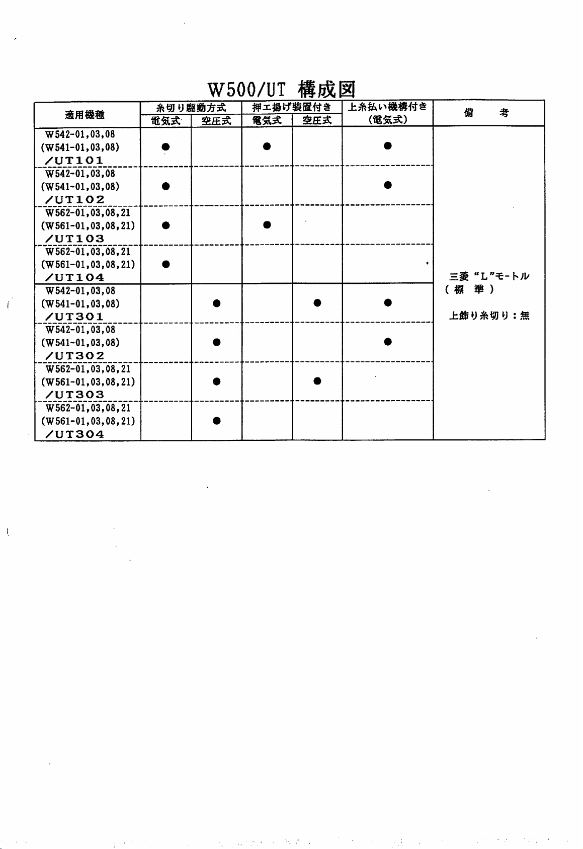
W542-01,03,08
(W541-01,03,08)
/UTIOI
W542-01,03,08
(W541-01,03,08)
/UT102
W562-01,03,08,21
(W561-01,03,08,21)
/UT103
W562-01,03,08,21
(W561-01,03,08,21)
/UT104
W542-01,03,08
(W541-01,03,08)
/UT301
W542-01,03,08
(W541-01,03,08)
/UT302
W562-01,03,08,21
(W561-01,03,08,21)
/UT303
W562-01,03,08,21
(W561-01,03,08,21)
/UT304
W500/UT
m #
•
•
•
•
•
•
•
•
•
•
•
•
•
•
1
HH
im
m)
•
•
Page 3
aufelz
CC0OT*(±,
<
m ^
W500/UT«a»mT-1-o
SEH 1
-co^^T
b
A>fc
T-zf)W0Mxtmft^<o&^x:t
^-9-zf-U
fitSttiBSffl®
3-
K®g!«si
y#1^5^ 4
•
—^
~ 1
2-3
—
^3
6~®
Biyav>±®a®
1
^
5
®
#ilttaiS®&BSilii
x»yx.i'
Sf'®<itjhfiB®«iy®?L-^-i'-®Siaj®ffiSiJ5i
vi/y-f
y 9 —
K(ifi)®®y#w-:3^
(ifi)®® y
V
l/y-f
K(«)i::*X^(ffi)®jtiS-
amss
®
Hiffi-
i^m^aim<»ms6
xT-^uTiiB®^®
—
XT-5SUTSB®ffiB
K1^
V® as —
u
I)
(B)®®
y
——
9
10
10
10
ii~i2
13
1^
—15
1®
""11
11
^11
1®
•>yvi^-
W500/UT-t-ii
W50oyur/^-y
English
(«)
t
edition
(«)®
-tt«—
y x i ^ —
starts
itB
from page
21,
18
19
43—58
Page 4
W500/UT^M#=
^
i"o
tto
vXi.
(fTlf-C'l'
tt.
imRU'E-Sf-lZ'DlM:
r ^ ± tAV^ - J: o T M $
^lC^t^c€«l±^5:C/'tBI5[C
oTH^'i
= X h
vrZ^-^-^f^-fflL^i-o
MmCDU'^lz
W500/UT^Eft=
1:•"/j T-E-^J o
f^^ij:W500-01CAX232/UT103
i-Xi,
i
TL
i-L
r ^^ 1" 0
^
1",
p"o
€ E
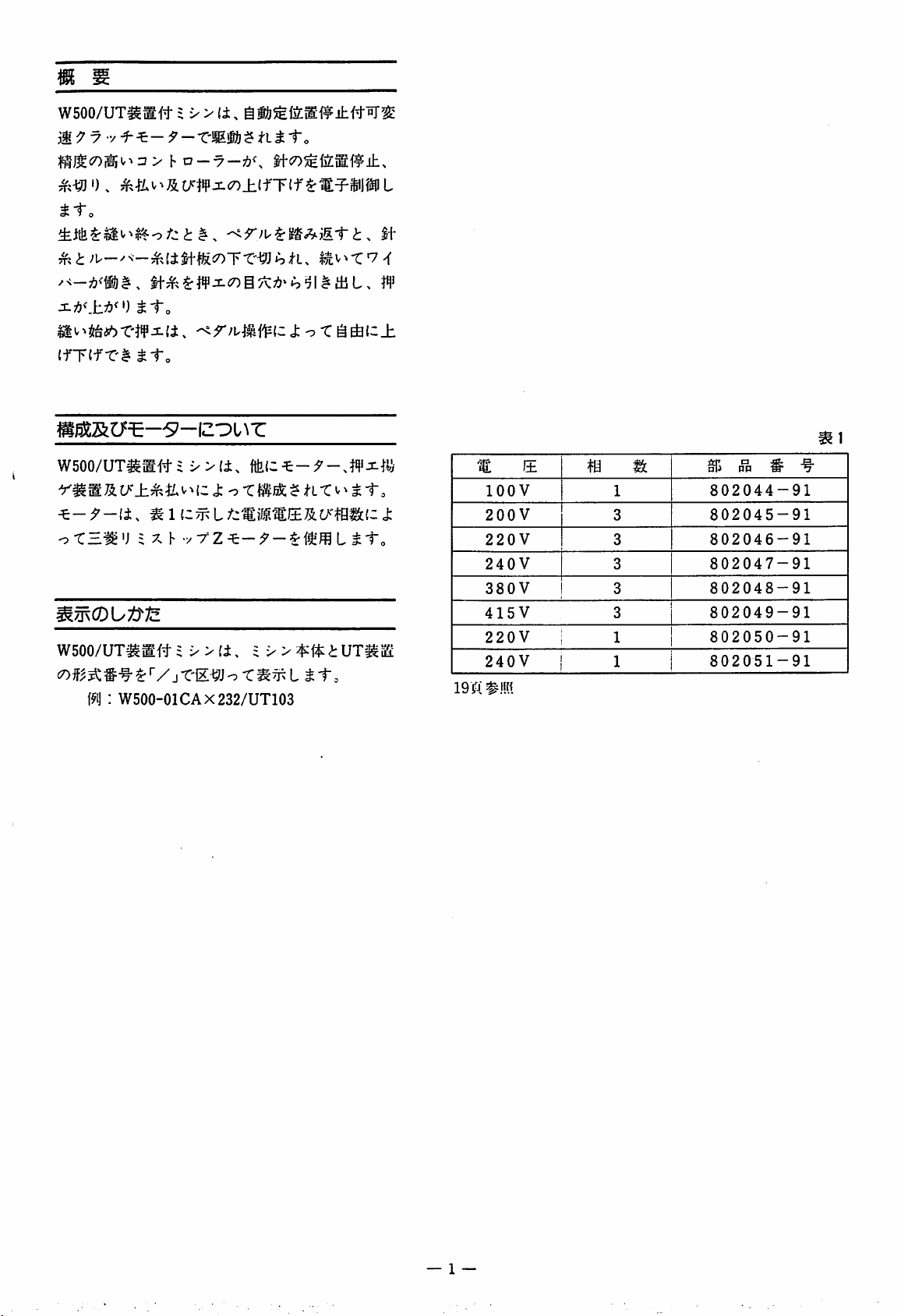
lOOV
J:
200
220V
240V
380V
415V
V
220V
240V
lOjTj
#!!«
m wl
1
3
3
3
3
3
i 1
{ 1 1
802044-91
802045-91
802046-91
802047-91
802048-91
802049-91
802050-91
802051-91
# ^
— I —
Page 5
4-«513
mi
019.5
4-025.5
284-
— 2 —
Page 6
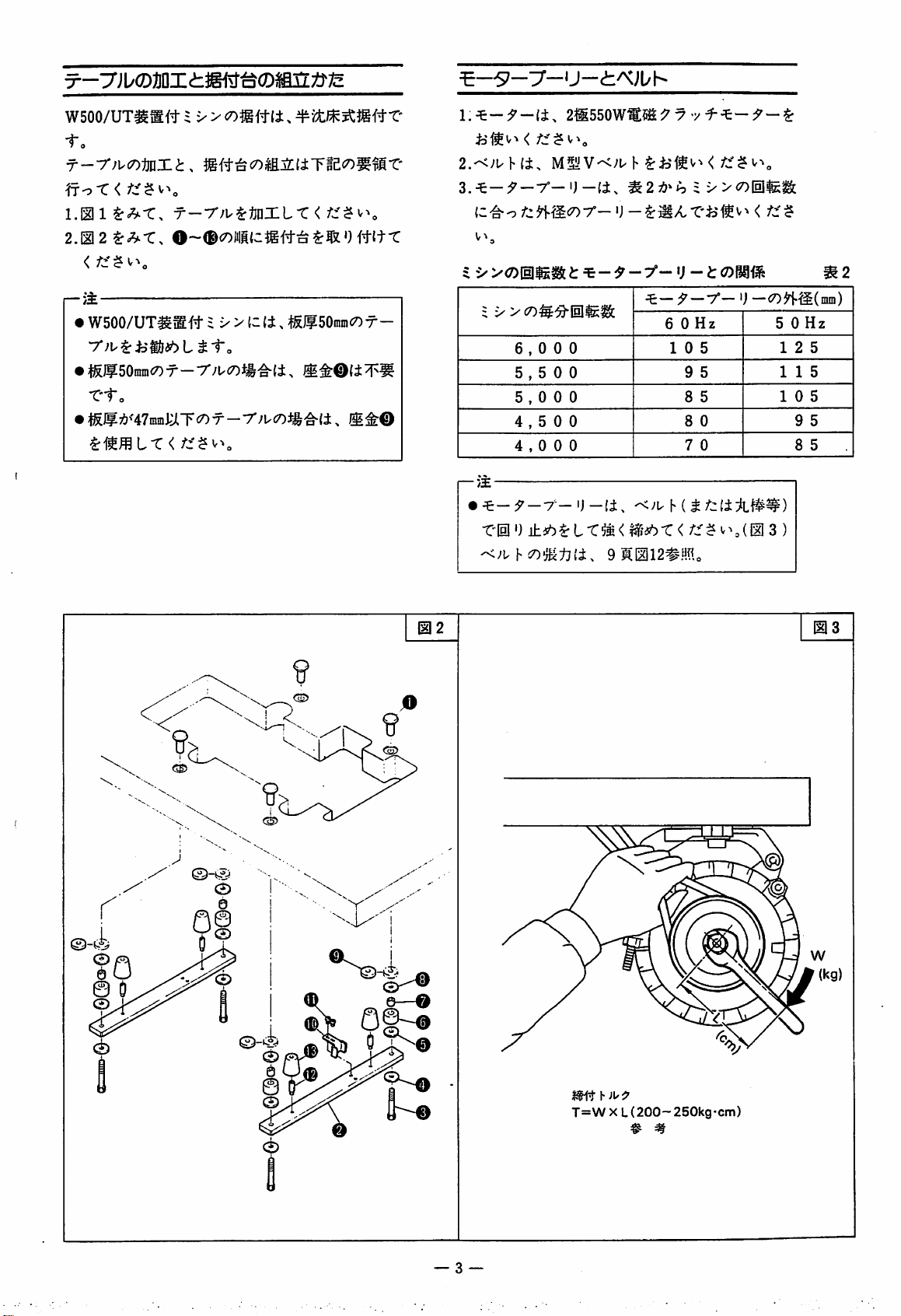
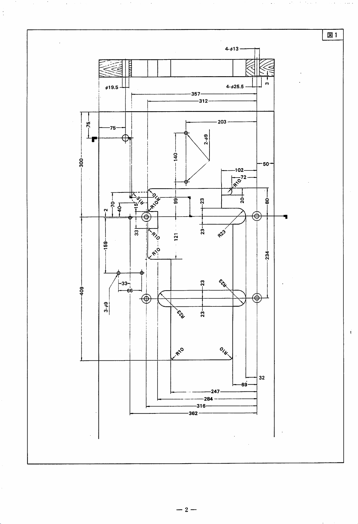
W500/UT^mft
•fo
n-oX<
l.mi^^X.
2M2^^X.
= V >
c7)$gft(i.
r--r;v^mxix
0~®<7)liiC|gftia
2.'<>'uh(i.
M5yv-<;uh
<
ftttt:
[—/i
•
WSOO/UT^M#
= V > {c
7*;^^i5i!)^6L^i•o
• l^)?50inm«7)T—•7'/Uc7)^|F'^(i,
X'to
•
W7i»H7mmJ.:JlT<7)T-r;K7)J-i'^{±,
(i,
tSIf
50^IIn(7)T-
9
m2
(—•/£•
•
6,000
5,500
5,000
4,500
4,000
^—9
—
*CI1!')
±ih^LX^^<l^idbX
h^O-IM-tKi,
X:—9 —
T—^}—ii.
9K1112#Mo
X—
0 —C7)^r|.g(niin)
6 0
Hz
10
5
9 5 1 1 5
8 5
8 0 9 5
7 0 8 5
l-
</"::'$
''^(H
3 )
5 0
12
10
Hz
5
5
US
9
h
JU:?
T=WXL(200-250kg-cm)
— 3 —
Page 7
G
qra
0
[MP
K
n
M
m
M-
V;
1^
U.
cn
el
✓N
4
M-
4
•
<•
4
-7-
>
4
r
•
X
n;
-r
c
O
is
c-
V
n:
H
m
is
P^v
m/
<-
n
OJf
>i
4
e
3
oo
to
fv
1
A
v»
a
V
n
/N.
OJt
(I
r\ r\
'
v;
>
o
-T-
3
a-
(1
f
5+ I
H
m
rA
'
1
a
iff
c
-t:
e
sm
±a
4 ®
^ 3
0
S
1
0
en
4
O
^SUj
ri
M-
G
1
©
9
r\
r~
n
i_
ow
rA
/N.
r~
rA
✓%
r)
3
am
®
/s.
e>»
nv
W
<r
ri
'Vc
n
o<
9x
•/
<-
o
28mm
— A =
Page 8
5
1117
— 5 —
Page 9
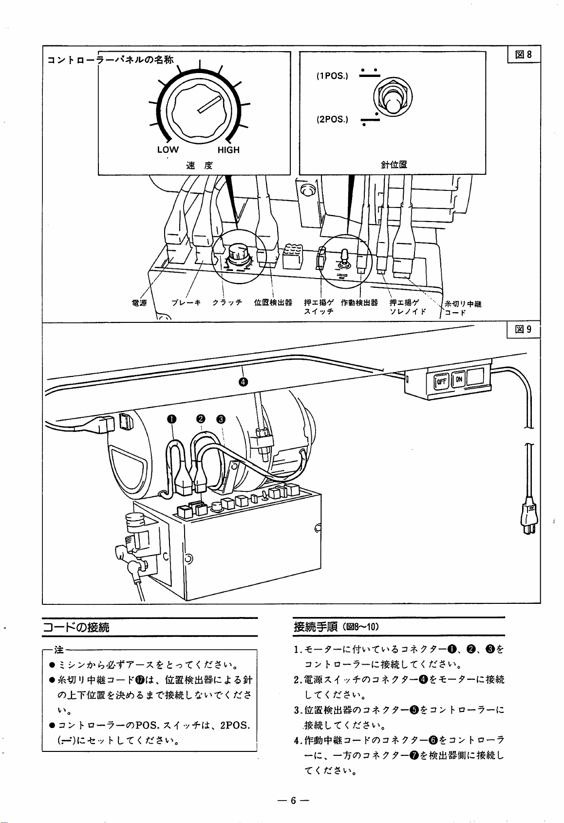
(IPOS.
(2P0S.
LOW
yu-dr
HIGH
Ifxjgy
jfxjgy
y L'/'TK
••
p-
HP
K
•-KCD^iu
(—/3E
• :^>-®'j
<n±riiLW.
• h
a-7-coPOS.
(r-*)(C-fevhLX
K®(i.
^'SiiUbht
<
t V^r-< ?
X-f
yf-fi,
2P0S.
\.X:-9-\,zH^^X^^h^^-^9
u > h n — y —
2.'S?®X'f
LX<
3.fS:ic#il±i^<7)=?
•y^C0:7
.^iS^LX</c'^v^,
X<
— 6 —
iz^^LX
K^on
4;
;f>^rJ'—0^
<
9-0.
/:f$
0,
> h a
—7—(C
3 > hC7—7
0$:
Page 10
•n
HI>^
II0003I
«
QQQ
OOOO
OOOO
Vi
04
71
15?
m
fV
fOc
r\
^
D8»
%
m »
IV
Page 11
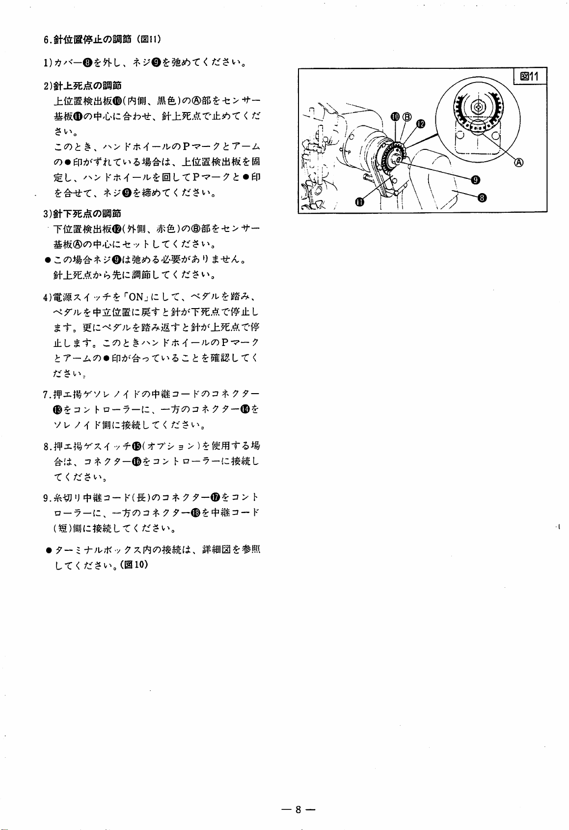
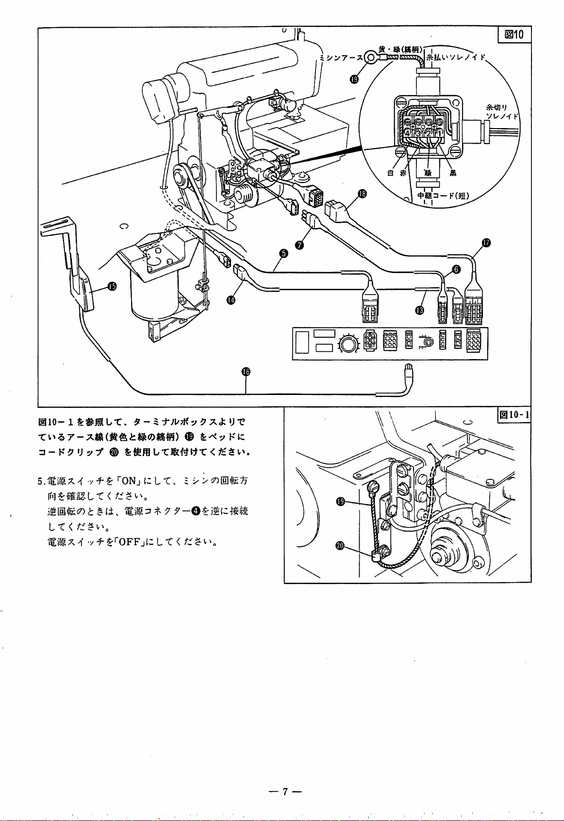
(011)
2m±n^.<Dmm
^>f&<D^04''C.^tC'^h-^. M-±.W.,^.X'±!ibX < f::
Z<X>t^.
^^>
3mTWMo)mm
nm^ihUibimL
4)Mx^""ONjlz
^^
4"21(5:^(-
±Lt'tc
>:T-A!7)»ep7:?>'^o-cv^^
$ V ,
7 u / /f KiO't'Tl^ =J— K^0:3 4 y —
®^;2>
vu
ha
KHJd^lifLLr
K'i-^^—>'K7)P-^—
K'tN^—-'u^lllL'CP-^—^7
LT,
Mi"t$-\-^'TW.AX^^±
K'i-x^—;uc7)prp—7
::t^mULXi
—y
——i7<7)r?
<
^ t T
t
—A
•EP
L
S,W^^%x'7^y{
r? 4 y
r <
9.-^-^'JJfiyjrj—
n
—7
—(C, —:4<7)74>i7
(M)fiij(c^i^^uLr
•
:^-
= X
LT
<
-/^(^(Try'i^
:7—r?
Y{^)<r>zi
<
(010)
3 >
> h n
—7—
y
;J^—©^4'li='—K
l^lHljl^#M
^7
> h
— 8 —
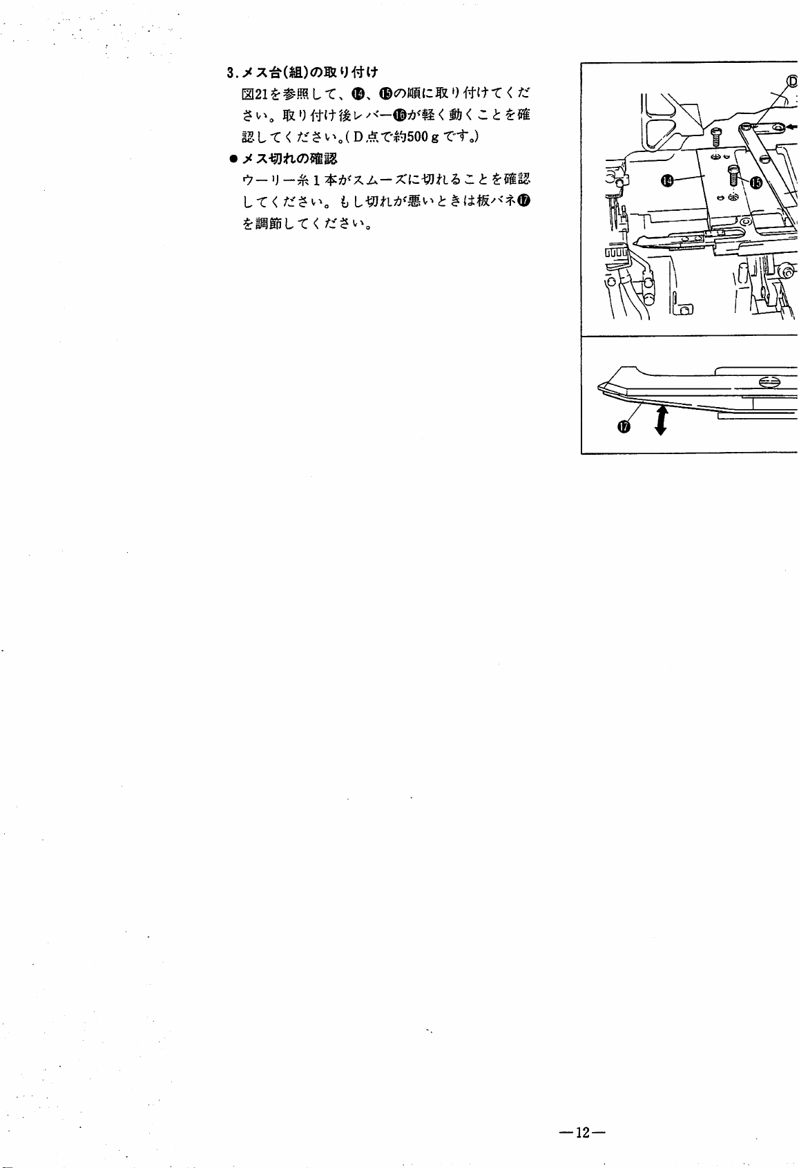
Page 12
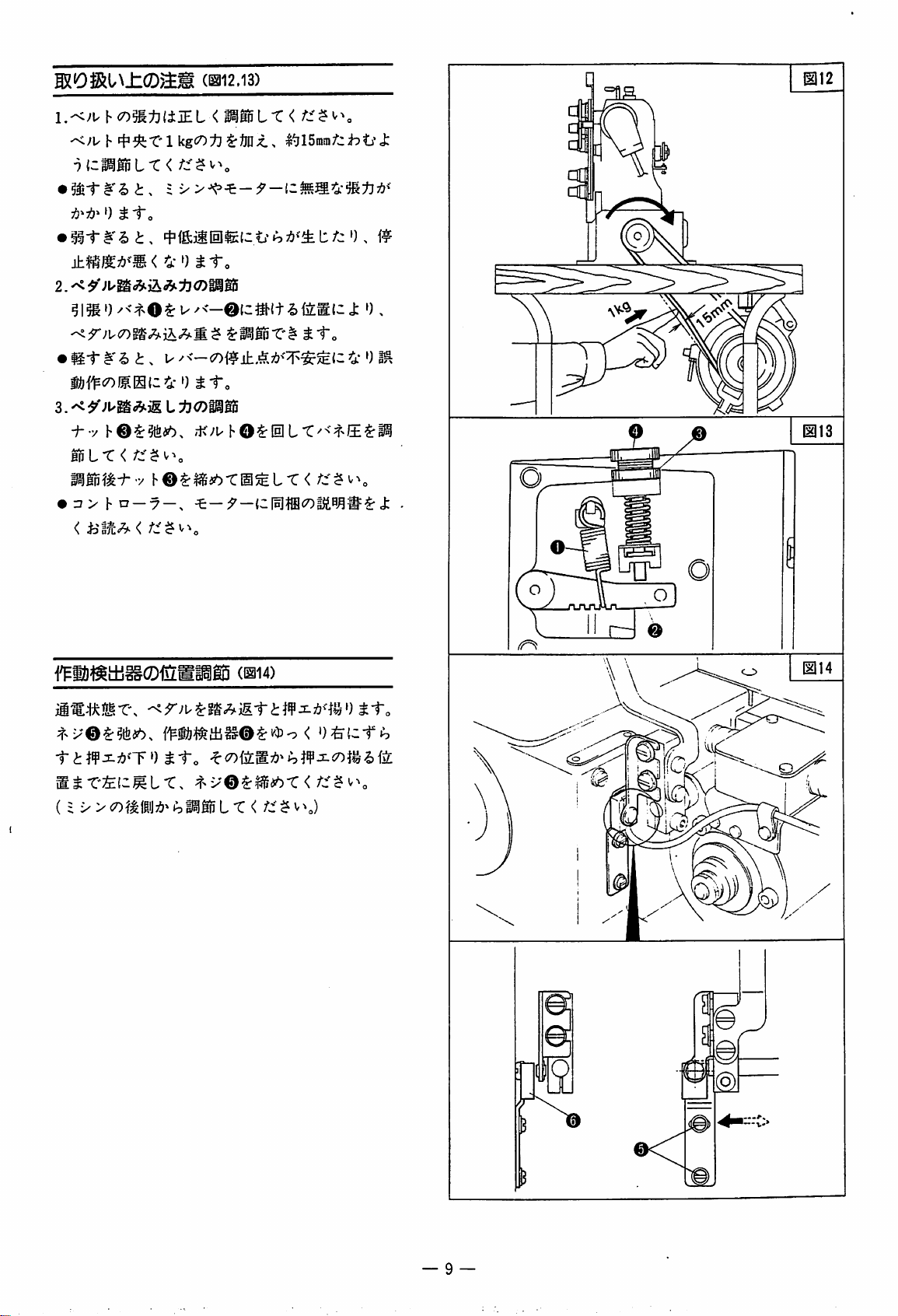
'<>'U h
2.
^
h
(7)^:b(ijEL
»)
tto
m2.i3)
<
c^iiSS
mmiX<
i&f^<50)f>S{z4-')
-f- y ,i<;u
lnL-C<
mmmx-y
•
:3>hn
*\
W.tx^\z%\^x.
ioaK<^
r::^^\
ho^msbxm^ix
—7
—,
*v
(i'>><x>m\m^hmBix<
$:l^|p-C'l'
^1"o
hOt!ilLt:^<?>/±^i^
—
(11114)
/::•^v^J
tto
<
r::^^\
m
— 9 —
Page 13
mmx'^ti-o
LX^^lz^jttto
iz^<
®-t-^^7!?^'-C"#^i-o
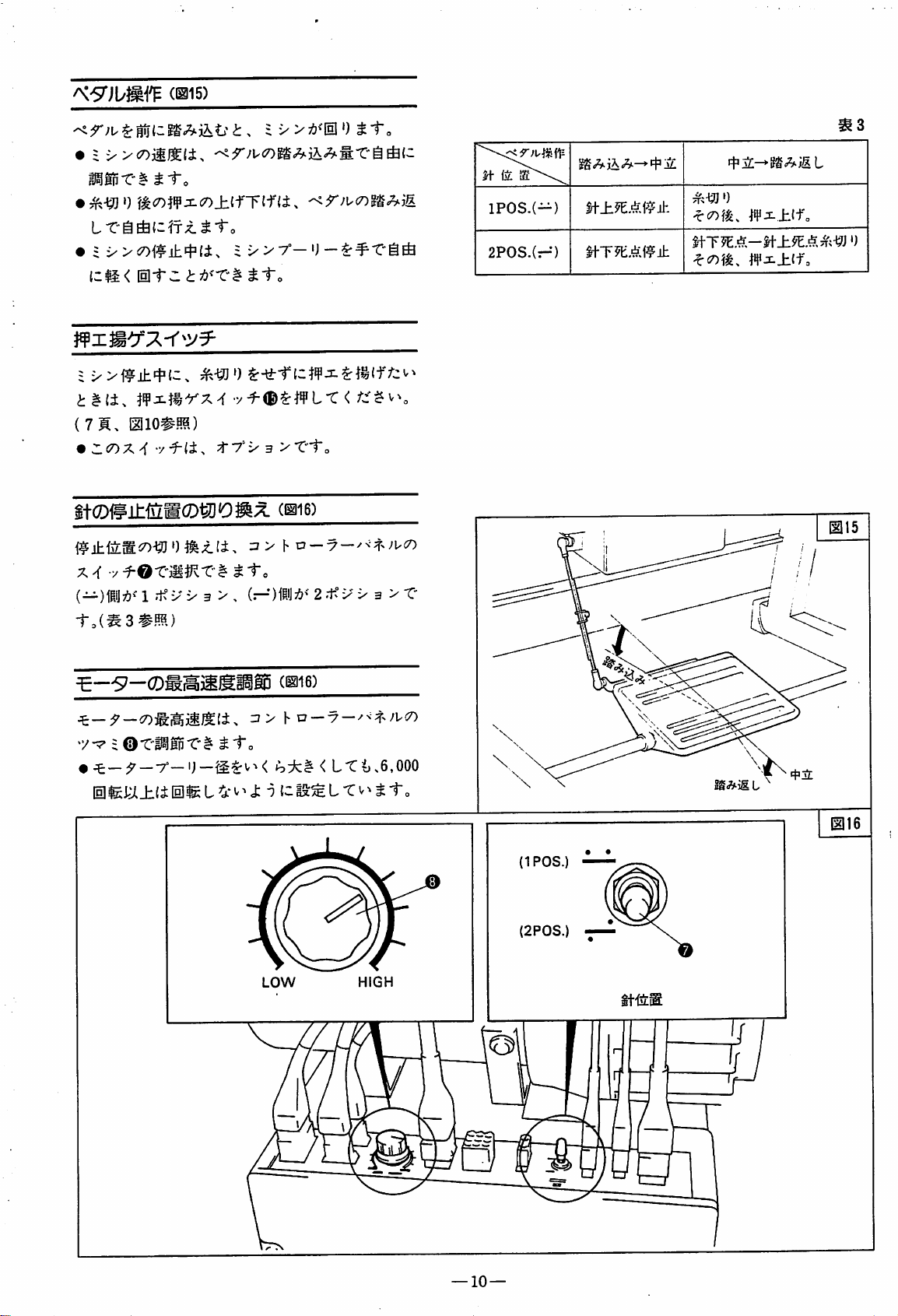
(1315)
IPOS.(-)
2P0S.(r-*)
thT51:i;f?il:
if<wn
UTW.A-^±9^.^A'i^}
0
i^(±.
(7M.
•
j^xtfrx^
miomm
wC7)X^•/tTi^B>XXo
%f(DW'±^m(DWD1^^
a>
x^
-y^oxmrKx^tto
(—)
jpjj7&^'
to(^3#m)
^-57-(
'/•7 =
@T-|^ln-C'^^1-o
• ^: —:7
—T'—"J—<
1 .t°y X 3 > ,
(—•)1PJJ:^?^'
L-t</"C'?
(1^16)
Vv-y-^-i^-^Jvco
2 .t: X 3 > T-
(1116)
LT^>6,000
v^
IPOS
(2P0S
LOW
HIGH
—10—
Page 14
Vby-f
Oftttr
2.y
uy-f
K(m)0TO1tl:)-73
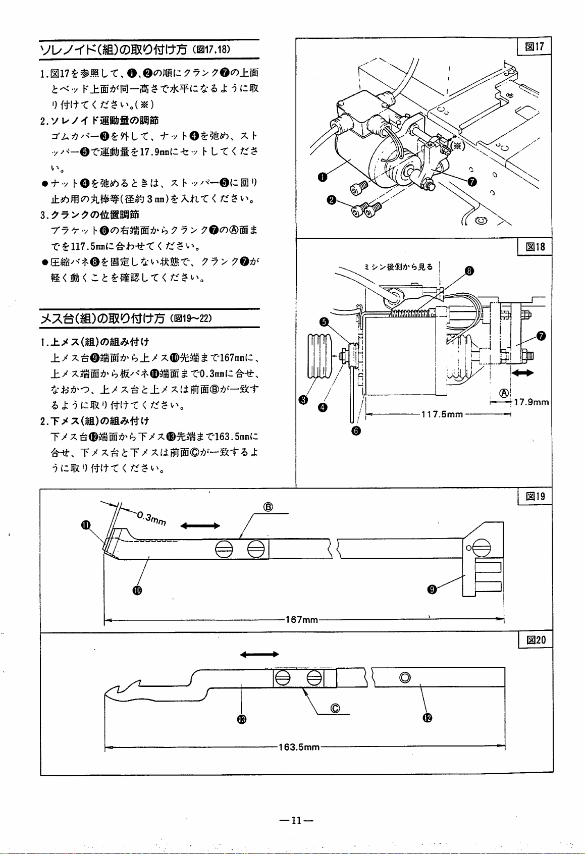
(BI17.18)
K±ffi7:>^'l^—l^?-r'7K¥{::=5.-^ J:
<
K3ii&a<?5iilis
•y-'--@-CJli&l;^17.9ram(C-b-/
•
"f"-yhO ^
7'7y-y
X^n7.5mmlZ^h-±X
^{ki''!)i>i ^
h
(i,
3
mm)^XHX
•
IK
j)!)<
zt^mm^ix<rz^^\
±/
X^©3^®^±9
-2)
J:^C|z')ft(t'C<
±/X^
i±/fc1"
Ty'X^©j^®7!?^:^Ty'X
Ty'X^tTy'X(±mj®©7:?'-iJc1--i)
X h
h9y>
<
(^19-22)
X®«t
®«
h
L-C<
••/''—©{C
< ^
90<^®M
9y>90^'
T"167niinH,
^ -C163.
/-w'^
HI')
t
SmtnC
J:
•v
5
'>
rl7.9mm
117.5mm
©
167mm
r
•163.5mm
—11—
©
Page 15
12 L-C< /Jf$ V
^(D
T'1^500 g
X'to)
^ I
L T <
/"si'^
^mmLX<
XJ.—
XlZ-\il]itlh
I'^hL-9Ji'L;!?^'Sv>
Z t
(J:
ra
12
—
Page 16
m2Z^^mLX.
X'M^LX<
—
7T'lTo-t
l.fzo
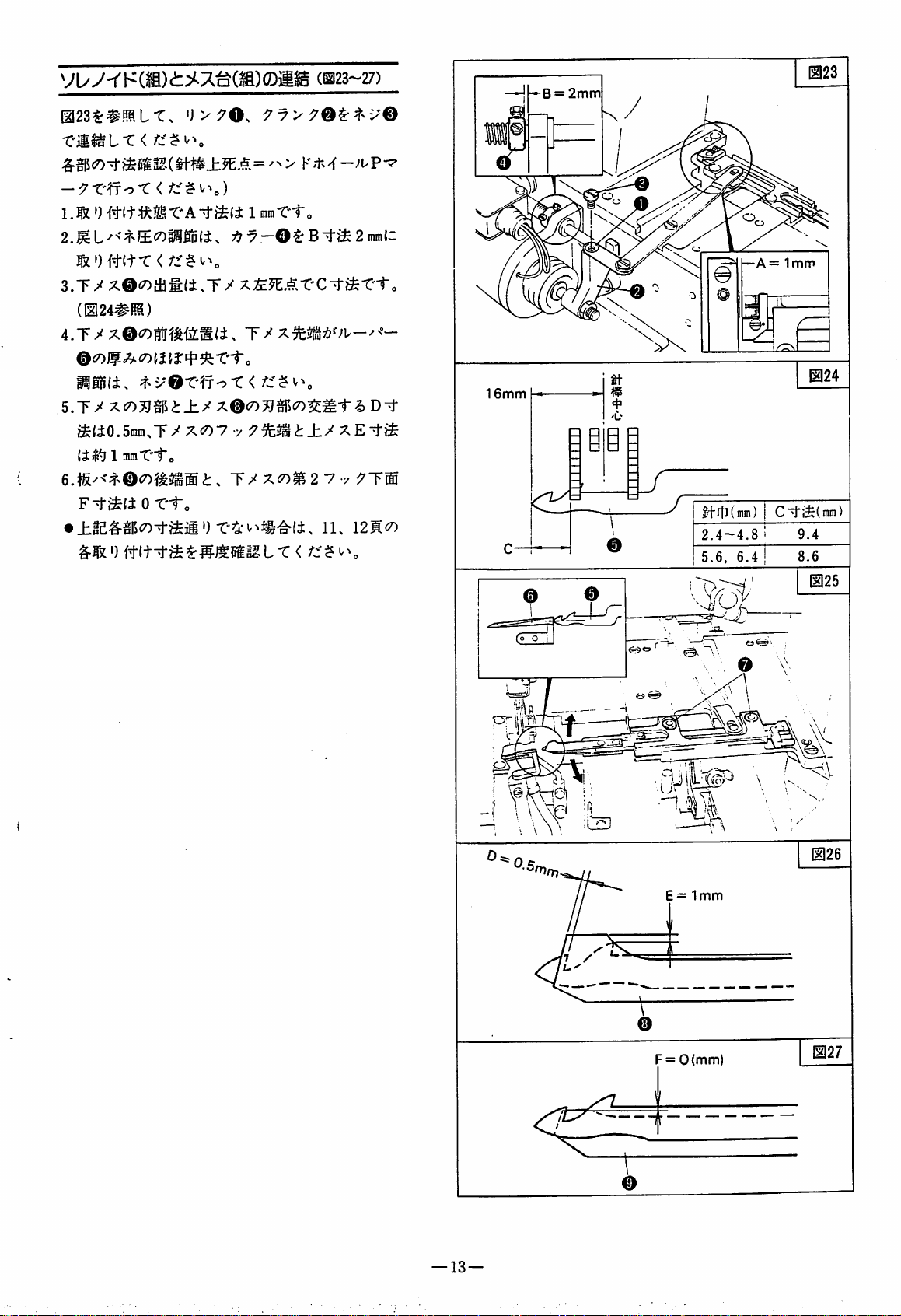
(1^23-27)
9y>
<
B =
2mm
1 mraT'i-o
fz')it{t-C<
3.T/
X@<50thfi(i.T^
(^24#HB)
@C7)If<7)
5.T^
(153:43
X(7)^^il$i±y
^(i0.5min,T/Xc7)7
1 mm-ei"o
F^^fiOT'i-o
•
')
it(t^^IX
x^^AXC-t^X-to
^-et'o
X®60^^jC7)$M1-^
y t
T/xx>^2
±^
7 y
11.
X E
12KXI
D^
"tiS
7Tffi
16mm
SI
—A=1mm
|+rtl(mm) C"4'iS(nim)
2.4-4.8
5.6,
6.4
^y.r|n
'4l
E = 1
F =
0(mm)
mm
—13—
Page 17
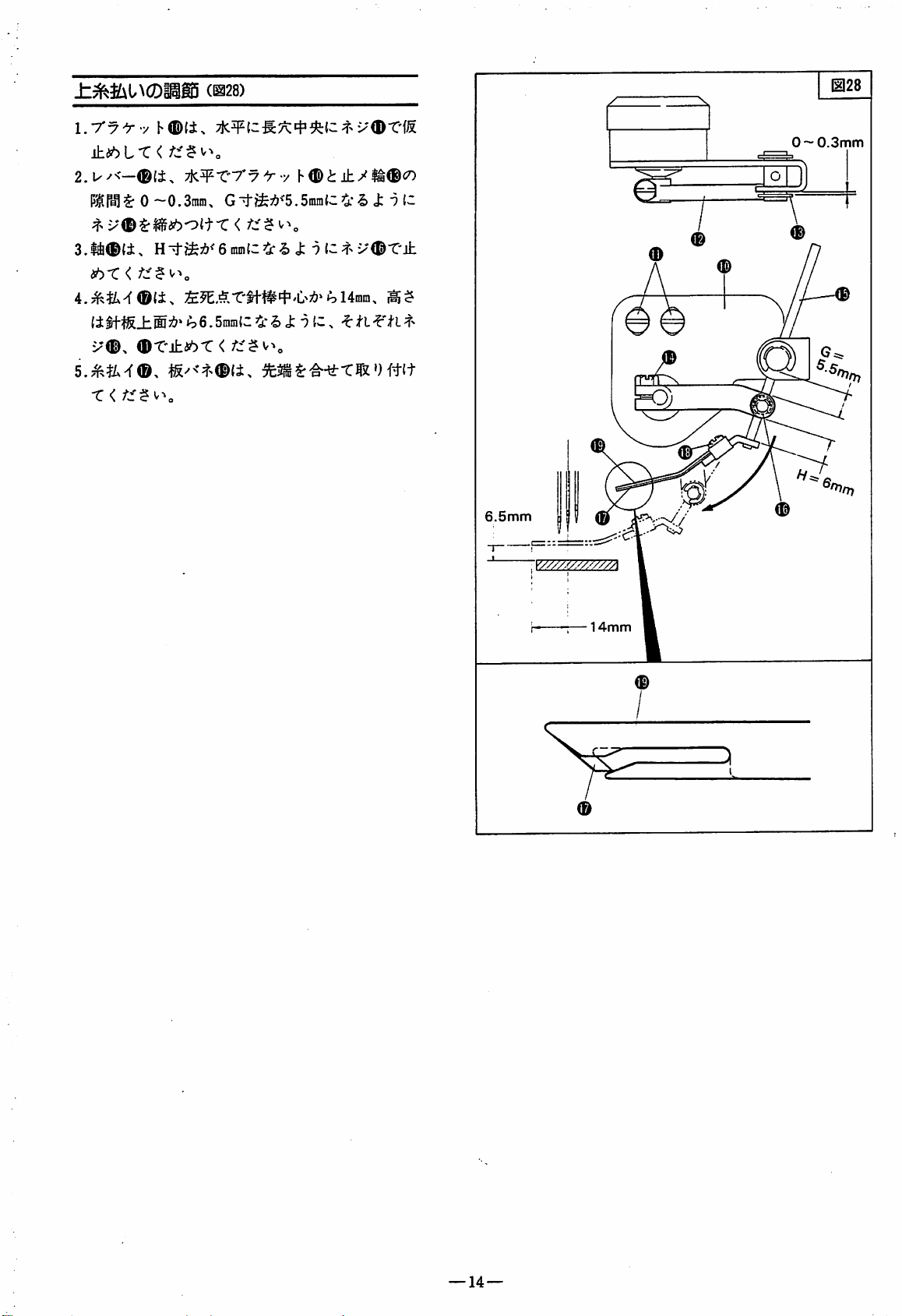
±:7^^Sit^CDiiiE5
(1328)
1.Ty'ry
±tbLX<r::^^^o
2.u^<—®(±.
0
3.l4®(i.
tbX
<
(itf'tS_hffi>i'*
v€)^
-C<
7K¥*C7'7^-y
~0.3tnm,
Gi-ife7&>'5.5mra{C^ J: i C
HTrfcfeA^'6[nin(Z5i:^ J:
»^6.5ram{zJ:")
X<DT1S
h®<J:±/lra®^0
6.5mm
yy///.^//////A
0~
0.3mm
®
14mm
—14—
Page 18
y
C5
CJM
0
(g
S
^<.0-4
^ 5-
W
<}
(t
A
9+
9-r 11
(g
a
^Jl
v»
0
V W- V
*4
®
94-
V»
rA
n ^ V
f^
'
ft
rr
(»
I
w
4V
3
® 3
v:s
rv
r
> s
"S
CO
V:
> ^
O
0
V.
(i!
4 5-
^ 0
m
e
r«
v;
>
O
3
0
I
0
4
av
1
n rj:
^ 4
9->
°
9+
Mb
a
-r;
-v
n ^
Pro
^ 4 s
3 ^ -
5r
4
1—
^ ^ i^
m 3 .
i:
d-»
O-
<hr °
rv
e
wt-
V ^ 3 ^
s ^ m 'vc
^ 4 4
^ w- S-
n> 4
f
4
9t-
W'
V
k
®
r>-
^
•!>
rt
rVc
3
3
tJJ
a>
=
a
n
f'
UOs
nr
as-
ii-
<r-
5+
'
)J>
dt %
3
3
O
-j
rA
✓S
a
m
r^
r\
r*
^
«/
<-
»->
V
4^
4
n
n
' 0"'
4
o
^ ?
-vjl
-^'
e
fVc
•<A.
rt
vjl
OJf
r -s V
).
V f4
xs.
V
v:
o °
n
av
r •
3
3_
cn
»->
3
0
k"
O
3
CO
m
3
3
CJI
5+
o-»
av
( 1
ttT
©
0
qra
dig
w
nmh
K
V:
o
nr
3 n
Pli 3
C;lD ^
1
iMp
rv
Ee
®
i:
T?"
r*:
r\
tj-
W-
M
S?
ov
jmH
to
>
/s.
is
r-
3
^2?
0
rt
rVc
01
©CdP
Page 19

oooo
ooo
n
m
•W
N
H
1
^ 1$. H ^
•od
s 4a 'W V
lEg
fl®
W s
D
m
G
H
W
4W
G
-5
IS
G
V ^ m
w ^ ^
s • . m
m
¥ W
m %
CO ^
CD
I ®
ai
Ml'
G m
® G n
12 , Ki .
»V G
1
CO
Page 20

xT-^UT^®0@21f
^-To
^0iKmX'^^Zt:
X
<tz^\i^.
#x7-£E$:±ij's
[ULr
•
xT-ffiS:Ttf'2>i:Sli,
$
v^.
—a
-yp«3lCX7-?!>^J^ori>-5i;
©
5~7kg/arflc!g|lSU
:^^[Rltc|sILT
tt±,
J<>)VX7
'X
< fc'
7 - 3 V
L/
-y-9'-ICjgig^
KU
V®#{ii
-
U=arjL
LT#ai
b-3i
-OtcfctofcKbvti,
1135
®'ec:ras<
v^o
—17—
Page 21

1.036$:#BaLT,
mt^'yh^±m
O,
O(0MlZ^'p>^O(D±
dif^
t-tk^
m)
ic
-sj;•?
ic
2.t/U
^V(D-ti&it
89.0mm
IS.Omn
ViTa
-e-T.
18.0mm
89.0mm
MbT<
mtr.
uvi'©,
^0m(Dmm:&mit.
l.Omm
T'f
i3m
o
(mm^)
=1.Omn
—18—
Page 22

•^
-f 7 >
W500/UTffl
IS
%
U ^
m E
m 40
no
(V)
m ^
(Hz)
60
—
rPpb#"^
802044A91
0 ^
x^7
m n
p o
—f±«—'
H ^
KJU
>t:*7
m E
# 40
100
$
110
(V)
H m
200
220
(Hz)
50/60
60
^
=E-'^-
m 40
802044-91
802044A91
= 40
802045-91
802046-91
^ m
-f
> K
iJ'' 7 -f
X5^:t
t°T
^rxT
V
ii
^
>-9-'—7'
h 7UZI
VI
U 7
'<hi-lx
+''J
to
I
v7
;^^-f
>
^ • -y •
;»3y7U—>
(^•1'
7U—
h )
'r>K^^v7
v'J7
5^ a X V 7
yH'Jt'7
lx/\V
>
X
vy
h
'J 7 > ^
XZL— V — 7 > K
7'j7
+
7*p:^
i?'!?!-
h
220
110/220
230
240
50
60
50
50
50
802050-91
802050-91
802050C91
802051A
802051-91
91
h'jxy-
7^')
7-r')t:>
77H2>5^>
^
/N°7
— 7 > K
7
4^ H
W
^ 7 > y
7 -f > 7 > K
^7
-r 4^'U 7
7 7
K 5
v>^\'7'x
7^:71—7-'>
7-f
yf - 7
X > 7 — 7
-f
:J''7
'j
h
7 'j
>7
x:^
7
ti^^m
-f
:#3'7U
MJ
K
h/\'x
110-120
220
220
220
200
220
240
240
230
220
220
220/380
380
346
380
380
415
380
220
60
60
50
50
50
50
50
50
50
60
802044B91
802044C91
802050-91
802050-91
802050-91
802050A91
802050B91
802051-91
802051-91
802051B91
802046A91
802046B91
802046-91
802048B91
802048-91
802048C91
802048A91
802048-91
802049-91
802048A91
802046-91
802048-91
380
7
50
802048A91
7 -f
-i^-
Page 23

Machine
Qodels
W542-01,03,08
(W541-01,03,08) ,
/UTIOI
W542-01,03,08
(W541-01,03,08)
/UT102
W562-01,03,08,21
(W561-01,03,08,21)
/UT103
W562-01,03,08,21
(W561-01,03,08,21)
/UT104
W542-01,03,08
(W541-01.03,08)
/UT301
W542-01,03,08
(W541-01,03,08)
/UT302
W562-01,03,08,21
(W561-01,03,08,21)
/UT303
W562-01,03,08,21
(W561-01,03,08,21)
/UT304
W500/UT
Thread
Erectoric
type
trimminng
mechanism
Pneumatic
•
•
•
Organaization
Electoric
foot
type
•
•
•
•
lifter
•
•
Pneumatic
foot
lifter
•
•
chart
Thread
(Erectoric
•
•
•
•
wiper
type)
A
note
HITSUBISI
Motor
Top
trimmer
(standard
cover
"I"
)
thread
: No
= Y e s
—21—
Page 24

INTRODUCTION
This manual contains the operating and servicing instructions of the Thread
Trimming
For other instructions, refer to the W500/UT instruction manual.
Mechanism
used on the W500/UT machine.
TABLE
GENERAL
COMPONENTS
IDENTIFICATION^
TABLE
DRIVING
POSITION
SOLENOID
CUTTING
OF
CONTENTS
DESCRIPTION
AND
MOTOR^
AND
MACHINE
MOTOR
PULLEY
DETECTOR
OPERATED
— 26
FOOT
THREADING
CORD
CONNECTION,CONNECTING
CAUTION
ADJUSTING
PEDAL
PRESSER
SELECTING
SOLENOID
POSITIONOFOPERATION
ACTION^
FOOT
LIFT
SWITCH
NEEDLE
(UNIT)
STOP
SETTING
REST
BOARD
AND
BELTING^
LIFTER
—
STEPS—
—
POSITION•TOP
ASSEMBLY
DETECTOR
— 32
SPEEDOFMOTOR
Page
23
23
23
24~25
25
—26
"27
28-30
31
31
—^32
32
^33
KNIFE
HOLDER
(UNIT)
SETTING
CONNECTIONOFSOLENOID
THREAD
THREAD
OPERATION
CONNECTING
PIPING
ADJUSTING
REMOVING
INSTALLING
WIPER
RELEASER
FOR
ADJUSTMENT
ADJUSTMENT
DETECTOR
FOR
THE
THE
PNEUMATICUTDEVICE
AIR
PRESSURE
DRAIN
CYLINDER(UNIT)
ADJUSTMENT
PNEUMATICUTDEVICE
CONNECTIONOFCYLINDER
W500/UT
W500/UT
(UNDER
PARTS
THREAD
LIST —
33-34
(UNIT)
— 39
(UNIT)
TRIMMER)
WITH
KNIFE
— 39
WITH
KNIFE
MOTOR
HOLDER
HOLDER
(UNIT)
(UNIT)
SPECIFICATIONS
^ 40
^43—58
35
-36
37
37
38
39
40
^41
—
22—
Page 25

GENERAL
DESCRIPTION
The W500/UT machine is driven by an electromagnetic
clutch type needle positioning motor. The micro
processor based precision controller controls needle
positioning, thread trimming, thread wiping and foot
lifting.
Pressing the pedal backward at the end of sewing
causes the looper thread to be cut off under the
needle plate. Then, the wiper takes out the needle
threads from the presser foot, and the presser foot
lifts. The presser foot can be moved up or down by
pedal action at the startofsewing.
COMPONENTS
The
W500/UT
motor and
thread trimming mechanism. The standard
MITSUBISHI
AND
machine
W500/UT
LIMI-STOPZ.
MOTOR
consists
ofafoot
machine equipped with the
motor
Various
motors
suitable
lifter,
for the voltage and phase are provided for use as
listedinTable
IDENTIFICATION
1.
The machine is shown by the machine type, gauge
and the UT device type number. Between them is a
slash
/.
Example:
W500-01CA
x 232/UT103
Table
1
PART
VOLTAGE
is
lOOV
200V
220V
240V
380V
415V
220V
240V
PHASE
1
3
3
3
3
3
1
1 !
802044-91
802045
802046
802047-91
802048-91
802049
802050-91
802051
NO.
-91
-91
-91
-91
See page 41.
—23—
Page 26

4-013
Fig.1
—
50
362
—
24—
Page 27

TABLE
BOARD
CUTTING
AND
ASSEMBLY
MACHINE
REST
For W500/UT machine, semi-submerged installation
isadopted.
1. Refer to Fig. 1and cut the table.
2. Refer to
board
Fig.
2 and
O ^ ® in
assemble
sequence.
the machine rest
DRIVING
The
MOTOR
machine
should
PULLERY
useamotor
AND
BELTING
and
belt
of
the
followingspecifications.
1. Motor: Clutch motor, 2 pole, 550 watts.
2. BELT: Vbelt. Type M
3. Motor pulley: Select an appropriate pulley
referring to Table 2.
^NOTE:
•
For
W500/UT machine, a table of thickness
50mmisrecommended.
• For the table of thickness 50mm,
unnecessary.
•
For
the
Washer
tableofthickness
0.
47mmorsmaller,
Washer
0is
use
Relation between Machine Speed and Motor Pulley Table 2
Machine speed (s. p. m.)
6,000
5,500
5,000
4,500
4,000
I-NOTE
Motor pulley diameter (mm)
60
Hz
105
95
85
80
70
• The motor pulley mounting shaft for W500/UT
machineis tapered. Accordingly, refer to Fig.3
and use the tapered hole motor pulley.
Fig. 2
50
Hz
125
115
105
95
85
Fig. 3
©-tvAi
0
0—O
—
25—
\
Page 28

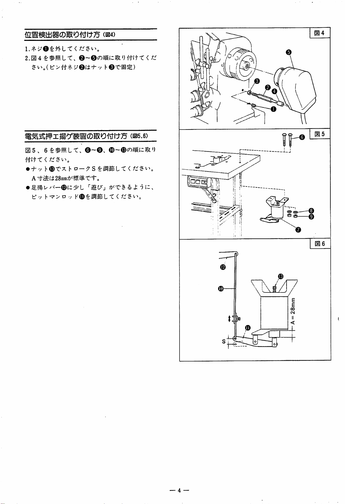
POSITION DETECTOR (Fig. 4)
1. Remove Screw
O-
2. Refer to Fig. 4, and install 0 and 0 in sequence.
(Fix Screwwith Pin 0 with Nut 0 .)
SOLENOID OPERATED
Refer to Figs. 5, and 6, and install parts 0 to 0 ,and
to 0 in
sequence.
FOOT
LIFTER (Figs. 5,6)
• LoosenNut 0 and adjust the stroke S.
Setting distance
stroke.
•
Adjust
has a little play.
Pitman
"A"
to 28 mm provides standard
Rod0so
that
Foot
Lift
Lever
0
—
26—
Page 29

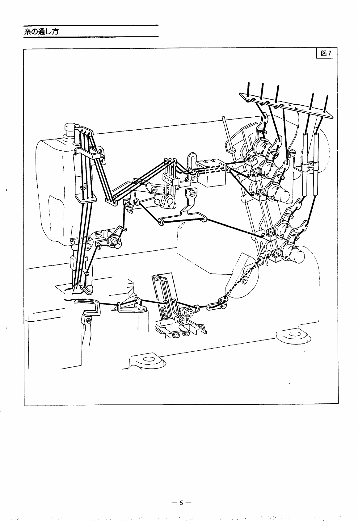
THREADING
Fig. 7
yj
u
5
—11—
Page 30

CONTROL
PANEL
(IPOS.)
(2P0S.)
Power
connector
source
LOW
Brake
HIGH
Clutch
Position
detector
Presser
lifter
foot
switch
Needle
Operation
detector
position
Presser
lifter
solenoid
foot
Thread
..junction
connector
trimming
cord
CORD
CONNECTION
I—
NOTE
Be sure to extend earth (ground) wire from the
motor
and machine to a good ground.
Do not connect Thread Trimming
Cord ® until the highest/lowest needle stop
positions have been set by the synchronizer.
Set
the
PCS
"2P0S"
switch
(.—•).
on
the
controller
Junction
to
CONNECTING STEPS (Figs. 8 ~ 10)
1.
Insert
Connectors
the controller. '
2. Insert Power Switch
Connector
3. Insert Synchronizer Connector 0 into
controller.
4. Insert Safety
Detector
into the controller, and Connector © into
synchronizer.
—
28—
and
Junction
of
the
motor
O into
the
motor.
Cord Connector
into
the
the
Page 31

Yellov
sreen
stripes
earth(ground)(o^Os3
&
Thread
wiper
solenoid
Thread
1
solenoid
trimmer
Connecttothe
&green
box showninFigure
See
storipes)
Figure
bed
10—1.
the
earth(ground)sire(yellow
(E)
coning out of the terminal
10.
Use
the
cord
crip
Z
Vhxte
Green
Junction
(short)
Black
cord
7
DOO
cr
?oo
5. Turn the power switch on. Pressthe pedal a little
and
check
machine.Ifthe
the
direction
machine
of
runs
rotation
in reverse,
of
the
re-insert
Power Connector O upside down.
Turn the power switch off.
—
29—
Page 32

6. To set
1)
Remove
the
needle stop position (Fig. 11)
Cover
O and
loosen
Screw
0 .
2) To set
3)Toset
the
upper
dead
pointofneedle:
Line
up the part® of
Plate 0
Sensor Baseplate
dead point of the needle.
If the P
of
detecting
P markwith the • mark, and tighten
Line
(inside,
markofthe hand wheel and the • mark
the arm do not agree, fix the upper position
plate,
turn the
the
lower
dead
up the part
Upper
Position
black
color) with the center of
0,
and stop it at the upper
handwheel
to lineupthe
Screw
point
of needle:
(§)ofLower
Position
Detecting
Detecting
Plate 0 (outside, red color) with the center of
Sensor Baseplate
• In this case. Screw 0 need
Adjust
4)
Turn
pedal.
and the needle stops at its lower dead point. By
further
at its
mark on the handwheel is lined up with the •
markonthe
first
the
Return the
pressing
upper
from
power
dead
arm.
®.
the
switch
pedal
down
point.
upper
on, and
the
not
be loosened.
dead
to the
pedal,
Then,
pointof
press
neutral
the
needle
check
down
position,
that the P
0,
needle.
the
stops
7. Insert Connector 0 of Presser Foot Lift Junction
Cord
into
the controller. Insert
Connector 0 into the solenoid.
8.
When
using
Presser
insert Connector 0 into
9. Insert Connector 0
junction
(long)
into
Foot Lift
the
Switch
the
controller.
of
the thread trimming
controller
the
other
0 (option),
and
the
other
Connector 0 into the relay cord (short) side.
•
For
connection
the detailed drawing.
inside
the
(Fig.
terminal
10)
box,
refer to
—
30—
Page 33

CAUTION (Figs.
12.13)
1. Keep the belt tension correct. Adjust it so that a
1 kg force on
deflectionofabout15mm.
• Excessive belt tension may overload the machine
and
motor.
the
centerofthe belt allows a
• Insufficient belt tension may cause the belt to slip,
and the needle may not stop correctly.
2.. To adjust pedal pressing force:
Pedal pressing weight can be adjusted by changing
the position of hooking Tension Lever Q on Lever
o
• Insufficient spring tension may cause the lever
stoppingposition unstable and lead to malfunction.
3. To adjust pedal pressing forward force:
Loosen Nut and turn Bolt O to adjust the
spring pressure.
Then, tighten Nut 0 to fix.
• Read well the guidebook enclosed in the controller
and
motor.
Fig.
13
ADJUSTING
DETECTOR (Fig. 14)
POSITION
OF
OPERATION
Press the pedal backward under the energized state,
and the presser foot lifts up.
Loosen Screw
Operation
0>
Detector
and slide slowly ' righfward
0,
and
the
presser
foot
will
drop. Turn 0 back leftward to the position for the
presser foot to lift up, and tighten Screw
0.
(Adjust from the rear side of the machine.)
—31—
Page 34

PEDAL ACTION (Fig. 15)
Press
the
pedal
forward
•
Machine
pressing
• After the thread has been trimmed, the presser
speed
amount.
and
the
canbefreely
machine
runs.
adjustedbythe
pedal
foot can be lifted up or downby pedalaction.
Whde
•
PRESSER
To
while
Switch
• This switch is available as
the machine is stopped, the handwheel can
be turned freely by hand.
FOOT
LIFT
SWITCH
lift the
pressr
foot
the
machineisstopped,
(Refertopage
without
23,
option.
trimming
press
Fig.
10)
Presser
the
Foot
thread
Lift
\
PEDAL
\^ION
NEEDLE^
POSITION
IPOS(-)
2 PCS
(.—•)
PRESS
FORWARD
NEUTRAL
\
Needle stops at
highest position.
Needle stops at
lowest position.
PEDAL
4
Table
NEUTRAL
PRESS
Thread
presser
Needle stops at lowest
position, thread is
trimmed at highest
needle position, and
then presser foot lifts
up.
PEDAL
BACKWARD
trimmed,
foot lifted.
then
3
SELECTING
The
needle
switch e
(u.)
sideisPosition1,and
(Refer to Table 3)
TOP
SPEEDOFMOTOR
The
top
Oon
the controller panel.
NEEDLE
stop
position
on
the controller panel.
speedofthe
motorisadjustable
STOP
can be
(Fig.
POSITION
(.—)
sideisPosition
16)
selected
bythe
• The motor speed is so set as not to rotate
6,000
diameterismade.
r.p.m.
however
large
the motor
(Fig. 16)
by the
knob
beyond
pulley
2.
(IPOS.)
(2P0S.)
• •
Pressing
backward
Fig. 15
Neutral
Fig. 16
LOW
HIGH
Needle
—32—
position
Page 35

SOLENOID
(UNIT)
SETTING
(Figs.
17,18)
1. Refer to
Fig.
17 and set O and O in
sequence
that the upper face of Crank O should level with
the upper faceof the bed horizontally. (*)
2.
Solenoid
Remove
stroke to
• When loosening Nut
bar (about 3 mm in diameter) into Stopper
3.
Crank
Set the distance between the right end face
stroke
Rubber
17.9mm
position
adjustment:
Cover
with Stopper
0,
adjustment:
loosen
Nut
and
set
the
0,
insert a round stopper
0.
Bracket 0 and the face ® of Crank0 to 117.5
mm.
• Make sure that Crank 0 lightly moves when
Compression Spring 0 is not fixed.
KNIFE
1.
HOLDER (UNIT) SETTING (Figs.
Setting
Set the distance between the end faceofUpper
Upper Knife
(Unit):
19~22)
Knife Holder0 and the edge of Upper Knife
0 to 167 mm, and the gap betweenthe end face
of
Upper Knife and the end faceofPlate Spring
to 0.3 mm, and yet set so that the upper knife
holder agrees with the upper knife at their front
faces (@).
2.
Setting
Set
Knife Holder and the edgeofLower Knife
agrees with the lower knife at their front faces
Lower Knife
the
distance
0 to 163.5 mm, and that the lower knife holder
(Unit):
between
the
end
faceofLower
of
so
See
from
a\A'3\
the
1
rear
sideofthe
Fig. 18
machine
17.9mm
117.5mm
Fig. 19
0
//
^
>©
•167mm-
Fig.
20
/
© 0
I
J
\ ©
<
•183.5mm-
—
33—
Page 36

3. Setting Knife Holder (Unit):
Refer to Fig. 21 and set (f) and is sequence.
After setting, make sure that
moves,
•
Checking
(about 500 g load at Point
Knife
Cutting:
Lever
(D)
® lightly
)
Check that a piece of woollie thread is smoothly
trimmed. It
not,
adjust Plate Spring
(p.
Fig.
22
-34-
Page 37

CONiSIECTION
KNIFE
HOLDER
OF
SOLENOID
(UNIT)
(Figs.23~
(UNIT)
27)
WITH
8 =
2mm
Fig.
23
Refer to Fig. 23 and connect Link O ^nd Crank O
with
Screw
Check the dimensionsofrespective parts so that the
upper dead point
markonthe
of
handwheel.
the needle bar agrees with P
1. Gap A should be 1 mm under the set condition.
2. To adjust the return springpressure,set CollarO
so as to make Gap B 2 mm.
3. Set the projection of
Lower
Knife0 to Size Cat
the left dead pointofthe lower knife. (Refer to
Fig. 24)
4. Set the positions of advance and return of Lower
Knife 0 so that the tip
approximately at the middleofthe thickness
Looper
0.
Adjustment should be made with Screw
5.
The
clearance
Datthe
of
the lower knife is
cross
of
the
of
0.
bladeofthe
lower knife with the bladeofUpper Knife 0
should
the tipofthe
be 0.5
mm,
and
the
clearanceEbetween
hookofthe lower knife and the
upper knife should be about 1 mm.
6.
The
clearanceFbetween
the
rear
end
faceofPlate
Spring 0 and the lower faceofthe second hook
of
the
lower
knife
shouldbezero.
• When the above parts are
not
exactly set at the
sizes as specified, re-check the setting dimensions
given on pages 33 and
34
16mm
Needle
bar
center
CM
Needle
5.6,
I
(mm)
00
—A=1mm
gauge
6.4
Fig.
Dimension
(mm)
9.4
8.6
Fig.
24
C
25
I
\\\
-35-
F =
E =
1mm
0(mm)
Fig.
Fig. 27
26
Page 38

THREAD
1.
2.
3. Shaft 0
4.
5. Set
WIPER
Temporarily
middle
Lever0shouldbehorizontal.
gap
0
the
Thread
the needle bar at the left dead point and its height
is 6.5 mm from the upper face
partofthe
between
~0.3
sizeHbecomes6mm.
0
and0so
Thread
their tips aligned.
ADJUSTMENT
fix
Bracket
elongated
(Fig.
<E)
horizontallytothe
hole
with
Tightensothat
Bracket0and
mm, and the size G is 5.5 mm.
shouldbestopped
Stopper
with
Screw
Wiper0shouldbestopped
thatitis14mm
Wiper0and
from
of
the needle plate.
Plate
Spring0with
28)
Screw
Ring0is
0 sothat
with
the
center
0.
the
Screws
of
6.5mm
Fig.
28
0~
0.3mm
14mm
36
—
Page 39

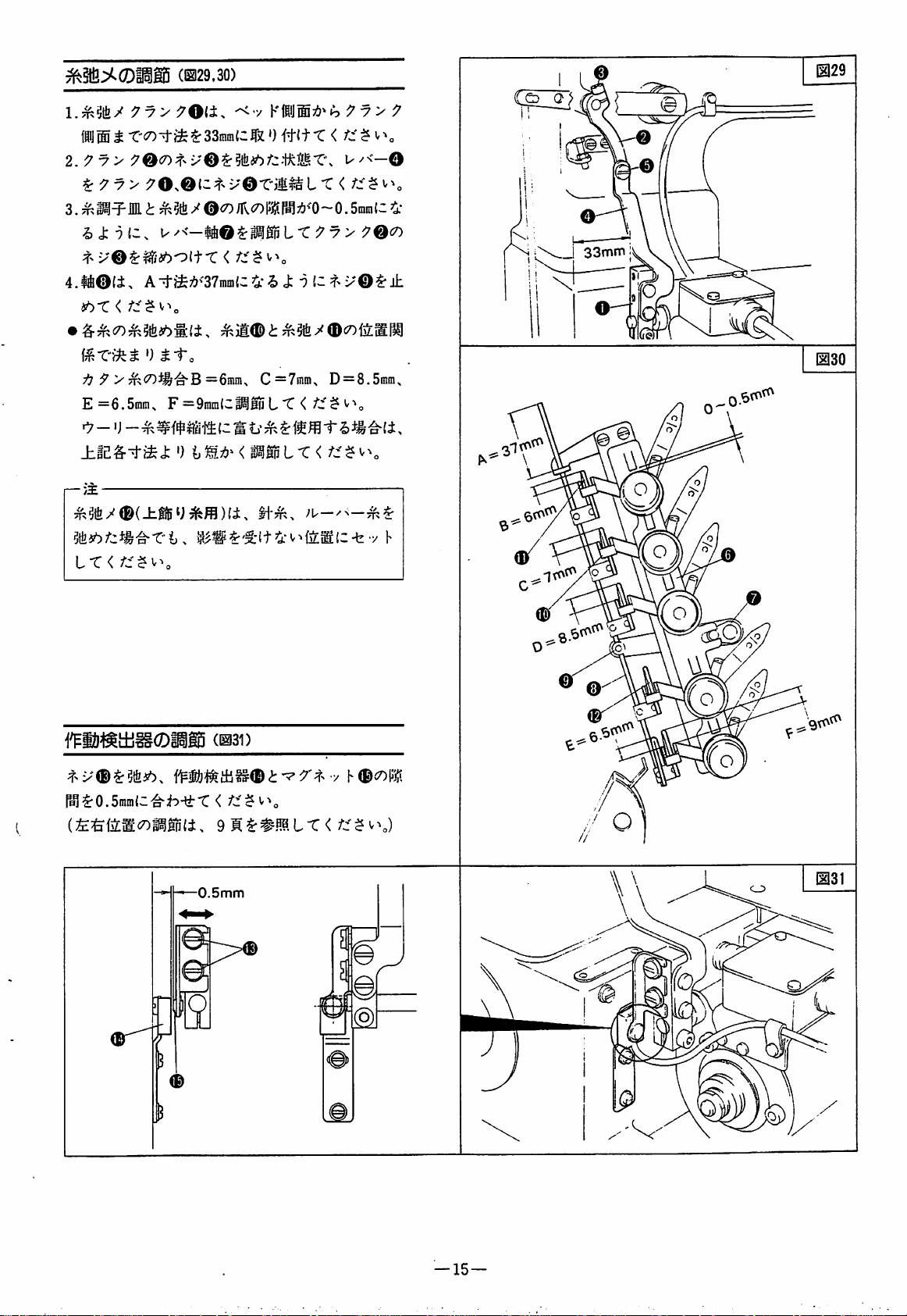
THREAD
RELEASER ADJUSTMEIMT (Figs.
29,
30)
Fig.
29
1. Set ThreacJ Releaser Crank O so
between
crank
2. With Screw 0
the
sideofthe
shouldbe33
bed
mm.
of
Crank 0 loosened, connect
and
that
the
the gap
sideofthe
LeverO and Cranks O and with Screw0
3. Adjust
thread
releaser should be 0 ~ 0.5 mm. Then, tighten
Screw 0 on Crank
4. Shaft 0 should be stopped with
the
Lever
Shaft 0 so that the gap betweenthe
tension
sizeAshouldbe37
disk
and
mm.
the.
claw
of
Screw
the
thread
0 so that
• The thread releasing for each thread depends on
the positional relation
and
For
B = 6
F = 9
For
Thread
cotton
mm,
mm
elastic
Releaser
thread:
C = 7
thread
between
mm,
D = 8.5 mm, E = 6.5 mm,
suchaswoollie
Thread
threads,
Guide
reduce
the clearances slightly.
-
NOTE;
Thread Releaser 0 (for upper spreader thread)
should be set to such a position
be
affected
even
when
the
looper thread are loosened.
needle
that
thread
should
and
not
the
J
33mm
0
Fig.
30
0
OPERATION
DETECTOR ADJUSTMENT (Fig.
31)
Loosen Screw 0 and set the gap between Operation
Detector 0 and Magnet 0 to 0.5 mm.
(For adjusting the right and left positions, refer to
page 31-)
0.5mm
©
—
37—
Page 40

earth(ground)
Yelloe
green
&
stripes
Thread
solenoid
wiper
Thread
solenoid
trimmer
Vhite
Black
Black
Yelloe
M
n
Junction
(short)
Red
Black
Vhite
cord
Connecting
Hake
connecting
Refertothe
the
electrical
the
other.
for
the
as
connecting
UT
pneumaticUTdevice
shovn.
steps,cord
device
the
note,adjustment
connection
of
of
38—
Page 41

Piping
Make
for
piping
the
pneumaticUTdevice
as
shown.
Adjusting
air
Pull knob®on
pop up a
air
little
pressuer
#To increase the
clockwise.
•To
decrease the
counter
—Note-
(Note
off
operate
air
cutter.
clockwise.
that
from
withapush
is
left
even
the
pressure
filter
for
compresser,
enoughinthe
regulator
withaclick.
5—7kg/a^.
air
pressure, turn
air
pressure,
after
the
of
o.
Then
turn
air
supply
the
cutter
the
valve
tubetoactuate
It
should
adjust
knob
knob
is
can
actuator
the
®
®
shut
Refer
Connected
if
the
to
Figure
to
the
air
Removing
Drain
32
compresser.
drain
collectedinfilter
draind out by pushing the
bottomtoright
or
regulator
drain
left
beforeitreaches
O ®ust be
hose O of the
buffle
'h
—39—
Page 42

Installing
cylinder(unit)
1. Refer to fig.36,and set Oand
so
that
the upper face of
level
with
horizontally.(5K)
2.
Air
cylinder
3.
Trun
the surface of right
the
upper
stroke
face
is
crank©
of
IS.Omm.
.edge
the
to dimention of surface ® of crank ©
89.0mm.
©in
sequence
should
bed
of bracket O
is
Connectionofcylinder(unit)
knife holder(unit)
Refer to
with
1. Gap A should be
RefertoP.13(Electrical
to
fig.
screw©.
adjustment
38, connect link
l.Ontm
of
the
other.
with
©and
under
type)the
the
crank ©
set
note
condition,
and
how
18.0mm
89.0mm
=1.Omn
—40—
Page 43

W500/UT
(UNDER
THREAD
TRIMMER)
MOTOR
SPECIFICATIONS
Nation
Voltage
GUATEMALA
COSTA RICA
VENEZUELA
IRAN
IRAQ
INDIA
URUGUAY
ETHIOPIA
KENYA
UNION OF SOVIET
TANZANIA THAILAND
TURKEY
NIGERIA POLAND
VIET-NAM
GRECE
SPAIN
MOROCCO
CAMEROON
PERU
( BEIRUT )
INDONESIA
SYRIA
TUNISIA
BOLIVIA
LEBANON
EGYPT
ST.LUCIA
NEW
ZEALAND
AUSTRALIA
CYPRUS
KUWAIT
SINGAPORE
FIJI
SOCIALIST
1-phase
no
220
110/220
230
240
(V)
Frequency
(Hz)
60
50
60
50
50
50
Part
of
the
802044A91
802050-81
802050-81
802050C81
80205IA9I
802051-81
nunber
motor
JAPAN
ECUADOR
KOREA
COLOMBIA
TAIWAN
TRINIDAD
UNITED STATES OF AMERICA
CANADA
PHILIPPINES
ARGENTINA
PARAGUAY
CHILE
CHINA
PORTUGAL
HONG
KONG
NETHERLANDS
FINLAND
SOUTH AFRICA
ENGLAND
FRANCE
DOMINICAN
ZIMBABWE
SWEDEN
SWITZERLAIO
AUSTRIA
DENMARK
Nation
AND
TOBAGO
REPUBLIC
1-phase
100
110
no
220
220
220
200
220
240
240
230
Voltage
~
120
(V)
3-phase
200
220
220
220
220/380
380
348
380
380
415
380
220
380
Frequency
(Hz)
50/80
80
80
80
50
50
50
50
50
50
50
80
50
Part
number
1-phase
802044-81
802044A91
802044B8I
802044C81
802050-91
802050-81
802050-91
802050A8I
802050B8I
802051-81
802051-81
80205IB8I
of
the
3-phase
802045-91
802048-91
802048A9I
802048691
802048-81
802048B8I
802048-91
802048C8I
802048A9I
802048-81
802048-81
802048A8I
802046-81
802048-81
802048A9I
motor
Page 44

PARTS
CATALOG
W500/
xT-^#x^^^^|-
UT
44-45
46-47
48-49
50-51
52-53
-54-55
-56-57
58
TABLE
COVERS
THREAD
THREAD TENSION MECHANISM
ELECTRIC
ELECTRIC
PNEUMATIC
PNEUMATIC FOOT
PART
NUMBER
OF
WIPER
THREAD TRIMMING MECHANISM
FOOT
THREAD
INDEX
CONTENTS
MECHANISM
LIFTER
TRIMMING
LIFTER
• KNIFE
MECHANISM
MECHANISM
-44-45
-46-47
-48—49
-50-51
-52-53
-54-55
-56-57
58
—
43—
Page 45

—
44—
Page 46

@2t
REF-
NO.
PART
9"
NO.
jr
-j
NAI1E
1122
10
1
350003
2
3
4
5
6
7
8
9
7043
350004
7096
240104
211301
4803
250010
7078
202588
Djr-
(n4)
•n\Y-
b5;<ci;MI12.5)
(114)
COVER
SCREW
COVER
SCREW
WASHER
SPRING
NUT
FLAT
SCREW
WASHER
WASHER
SPRING
—45-
Page 47

—46—
Page 48

THREAD
WIPER
MECHANISM-KNIFE
MECHANISM
REF.
NO.
10
11
12
13
14
15
16
17
18
19
20
1
2
3
h
5
6
7
8
9
PART
9"
jr
811045-
748005
7019
350031
306553
202522
7019
350026-
350026
4500
350027
200555
7009
350028-
350032
350033
350034
7008
350053-
350000-
NO.
:
'j
-91
-92
-91
-91
-91
9^5T9h
fDZV""
9599(9^)
9599
b5^^9^
9^99Tb®9
b5T9^
•<hn5-<
b5T9"
9^599h
(n4)
(N4)
(P15)
(113)
(113)
(9^)
NAME
SOLENOID
CLANP
SCREU
BRACKET
GUIDE
RING
SCREU
CRANK
ASSEMBLY
CRANK
SCREU
PIN
RETAINING
SCREU
BRACKET
THREAD
FLAT
SPRING
UASHER
SCREU
KNIFE
HOLDER
BRACKET
QT
1
2
2
RING
ASSEMBLY
UIPER
ASSEMBLY
ASSEMBLY
21
22
23
24
25
26
27
28
29
30
31
32
33
34
35
36
37
38
39
40
350014
350013
240132
7094
350015
7095
350023
7097
350024
350025
7031
350016
350021-
7031
240131
350018-
350017
350019
350020
7098
-91
-91
bjr-
U99
9^99TT9^
b5T9^
b5T9'^
u9:^2
b5T9^
9^5T9h
b5T9^
799l9jrT
9'^599h
tr5T9''
79tT
(115)
•(I13)
(n2.5)
(112.5)
(112.5)
(n5)
LEVER
LINK
UASHER
SCREU
GUIDE
SCREU
LOUER
SCREU
LOUER
UASHER
SCREU
UPPER
BRACKET
SCREU
SPRING
UPPER
UASHER
FLAT
SPRING
BRACKET
SCREU
KNIFE
KNIFE
KNIFE
ASSEMBLY
KNIFE
HOLDER
HOLDER
-47-
Page 49

48)
@~<S),@-®X3
@X2,®
24ctf-fiB 0 : m
2-Needle
Without
top
cover
thread.
49)@~(i),®)~®X3
•) : t
2-Needle
With
top
cover
thread.
-48-
50)®-®
@X3,i
3-Needle
Without
0 : M
top
)~®X4
cover
thread.
51)®-®.®-
@X3,®,®
3-NeedIe
With
top
cover
_
thread
X5
Page 50

THREAD
TENSION
MECHANISM
REF,
NO.
10
11
12
13
14
15
16
17
18
19
20
1
2
3
4
5
6
7
8
9
PART
7^
W
350036-92
350036
4531
350037
7027
350038-92
350038
4531
7066
202868
350039-91
5382
350043
200983
4554
350042
350047
350045
4554
350046
NO.
'j
9579(9=)
9579
t5:j:7^
bi^-
t5:?:7''
9579(9=)
9579
bjr-7^9
794^^7
7^9
h;>t47^
4jb9^-
(N5)
(115)
(n5)
VC5
(113)
(113)
NANE
CRANK
CRANK
SCREU
LEVER
SCREU
CRANK
CRANK
SCREU
SCREU
UASHER
ASSEI1BLY
ASSEMBLY
LEVER-SHAFT
SCREU
HOLDER
RING
SCREU
SHAFT
HOLDER
THREAD
SCREU
HOLDER
RELEASER
QT
ASSEMBLY
2
3
4
21
22
23
24
25
26
27
28
29
30
31
32
33
34
35
36
37
38
39
40
41
42
43
44
45
350045
4554
254005
254006
350044
7019
306301
5447
254010A91
208447
208448
201037
208450
210319
1817-2A
254010B91
201086
254010C91
201068
206203
350048
206202
350049
7019
167079
TMJb;^
h;>t47''
9^5r2h
777T
b547''
tV]Y
594
(113)
(114)
Uir4
•<h4397(9=)U30)
439779h
hMV
Tr
797l9jr4(439)
W5
43977^5
43974"9
-rh4397(9=)(439)
797290"4(429)
-rh4397(9=)(7"1'9)
79729n"4(7"1'9)
-rh=4
4K43979"T
2^®-9-
-rh=4
b547"
(114)
THREAD
SCREU
BRACKET
THREAD
GUIDE
SCREU
SPRING
LATCH
TENSION
POST
SPRING
TENSION
CAP
DISC
SCREU
TENSION
TENSION
TENSION
TENSION
THREAD
THREAD
TENSION
THREAD
SCREU
EYELET
RELEASER
RELEASER
NUT
NUT
BUSHING
SPRING
STUD
NUT
SPRING
NUT
SPRING
LEAD-IN
TENSION
POST
GUIDE
ASSEMBLY
(HEAVY)
ASSEMBLY
(MEDIUM)
ASSEMBLY
(LIGHT)
GUIDE
GUIDE
COLLAR
(HEAVY)
(MEDIUM)
(LIGHT)
4
8
1
1
1
2
1
1
3
3
3
3
3
6
3
1
1
1
1
5
5
5
1
1
1
46
47
48
49
50
51
7019
7019
350054B91
350054C91
350054D91
350054E91
b547"
b547"
T>ya>
T»3>
T>y3>
T>y3>
(114)
(114)
(75)
(75)
(75)
(75)
SCREU
SCREU
TENSION
TENSION
TENSION
TENSION
—
49-
CONTROL
CONTROL
CONTROL
CONTROL
MECHANISM
MECHANISM
MECHANISM
MECHANISM
34^^88
see
pl'ge
34
1
2
1
1
1
Page 51

50—
Page 52

THREAD
TRIMMING
MECHANISM
REF.
NO.
9
10
11
12
13
14
15
16
17
18
19
20
1
2
3
4
5
6
7
8
PART
9"
ir
811044-91
750014-91
760149
760150
7018
750015
4020
9A2519
747005
7019
350050
7009
350005-RA
4518
811048-91
4531
350008-91
4500
350011
240130
NO.
-j
5-^711/1^^
b5aL'^
?Tu20\VZ
V02~)9
(114)
(n4)
(113)
(115)
(n5)
NAUE
SOLENOID
TERI1INAL
TERMINAL
COVER
SCREU
TERMINAL
SCREU
INDICATION
CORD
SCREU
BUSHING
BRACKET
SCREU
BRACKET
SCREU
SOLENOID
SCREU
BRACKET
SCREU
SHAFT
SPRING
ASSEI1BLY
BOX
ASSEMBLY
BOX
BRACKET
PALTE
ASSEMBLY
ASSEMBLY
QT
1
1
1
1
2
1
2
1
3
2
1
2
1
3
1
3
1
3
1
2
21
22
23
24
25
26
27
28
29
30
201665
5084
350012
4808
201665
5084
7094
240062
4820
7088
1)5-
Qyi}0ZV'^/C3
03-j0
DVUOfVh
1)5-
•91l97'Vh
•!VD979h
U79I-
(115)
(n5)
COLLAR
SCREU
CRANK
NUT
COLLAR
SCREU
SCREU
UASHER
NUT
NUT
1
2
1
1
1
2
1
1
1
1
—51—
Page 53

—52—
Page 54

ELECTRIC
FOOT
LIFTER
REF.
NO.
3
7
9
10
11
12
13
14
15
16
17
18
19
20
1
2
4
5
6
8
PART
9^^
IV
306566-91
4751
206337
4808
306334-FD
4515
748006
4009-1
303335
306339
811017
306335
4515
306338
306337
4808
306336
742092
306791
306793
NO.
'j
9U'V9°(3A)
b5;iCL'VC5
yyviowz
t'DZV''
b":;
oynoty^
bjr-
(116)
(116)
NAI1E
FOOT
BOLT
UASHER
NUT
BRACKET
SCREU
LIFTER
CLAnP
SCREW
UASHER
SPRING
SOLENOID/FOOT
BRACKET
SCREW
KNUCKLE
PIN
NUT
LEOER
JUNCTION
PITHAN
ROD
(SHORT)
CORD
ROD
LIFTING
ASSENBLY
QT
1
2
2
2
1
4
1
1
1
2
1
1
4
2
2
1
1
1
1
1
21
22
23
24
25
26
27
28
29
30
31
32
33
34
35
36
37
38
39
40
41
42
43
44
45
306792
2022-4
306795
201166
802044-91
802045-91
802046-91
802047-91
802048-91
802049-91
802050-91
802051-91
742272-91
742089
742227-91
748002
716014-91
350051
2905
7019
201185
748005
7018
201185
810010-91
ovwru^'/cio
oub"
:>
Lt-Slb/l
000,53/90
Lf-Mb/2000,390
Lt-hJb/2200,390
Lt-Mb/2400j390
Lt-Mb/3800,390
Lt-Mb/4150,390
Lt-Mb/2200,53/90
Lt-Mb/2400,53/90
^200-1'3-hVl'h1^U(53/)
003/3/94:
r-lOO-TD-h"
^lOOl'D-KV-rh4:"J(?lO)
95123/
ir3/h^
003/3/194:
0^509h
b54^3/''/C5
b54^3/^
t-r03/
'V7}''Z
lO^'ZVhiO^)
(114)
5iJ90°(2A)
(114)
CONNECTOR
SCREW
PITHAN
COTTER
L-nOTOR/1000,1-PHASE
ROD
PIN
(hediuh)
L-nOTOR/2000,3-PHASE
L-I10T0R/2200,3-PHASE
L-nOTOR/2400,3-PHASE
L-NOTOR/2800,3-PHASE
L-I10T0R/4150,3-PHASE
L-I10T0R/2200,1
L-I10T0R/2400,1-PHASE
JUNCTION
JUNCTION
JUNCTION
BAND
CORD/THREAD
CORD
CORD/THREAD
DETECTOR
BRACKET
SCREW
SCREW
WASHER
CLAnP
SCREW
WASHER
HAGNET
ASSEHBLY
-PHASE
TRIimiNG
TRIimiNG
See
pages
41
1
1
1
1
1
1
1
1
1
1
1
1
1
1
1
1
1
1
1
1
46
47
48
49
50
7027
240062
350035
107723-05
4818
b54^3/^
'V1}''Z
b®
DyZZV
7h9ir-
•9JJ509h
(n5)
SCREW
WASHER
PIN-SCREW
STOPPER
NUT
•53—
1
1
1
1
Page 55

—
54—
Page 56

PNEUMATIC
THREAD
TRIMMING
MECHANISM
REF.
NO.
10
11
12
13
14
15
16
17
18
19
20
1
2
3
4
5
6
7
8
9
PART
350190-91
750014-91
760149-KA
760150
NO.
7018
750015
4020
9A2519
747005
747006
7019
350050
7009
350185
562022-91
4567
601095
600010
600024
600016
'y
y ^ - ( ilg
S 11/ Jj* y X
)
^ ^ IP Jl? ^ X *
7 9 X
¥ ^ y / M 4
^ { 4 ffi )
^ ^ / M 2 .
u - v V y
Z2
- \r ^ y y
5
3.
3,
^ ^ y X m 4
^
>T
V h
y / VI 3
^ ^
>r
V F
¥ ^ / M 3
•7^
a - y
3 -
^ a -
•;/
(iia
NAME
CYLINDER
)
TERMINAL
TERMINAL
CAP
SCREW
TERMINAL
SCREW
INDICATION
BUSHING
BUSHING
SCREW
BRACKET
SCREW
BRACKET
SOLENOID
SCREW
CONNECTOR
TUBE
TUBE
TUBE
QT.
COMPLETE
BOX ASSEMBLY 1
BOX
BOARD
PLATE
VALVE
1
1
1
2
1
1
1
2
1
2
1
2
1
1
2
3
1
1
1
21
22
23
24
25
26
27
28
29
30
31
32
33
34
35
36
37
38
513065
350187
601095
350008-91
350011
350188
350005-RA
4561
4518
350186
350012
4808
201665
5084
240062
4820
7088
7094
V »; > y -
y 7 ^ 7 h
^ V h
u
- V- -
^ ^ T y h
^ ^
i/
j/
^ ^ y / M
i/
3 ^ > h
VL
(jia
5
.6
^ ^ y ^
A #1 7 h / M
ii
^ —
A ^ ^ / C 5
V h / M
U 7 P / M 5
® ^ / M 5
CYLINDER
BRACKET
CONNECTOR
BRACKET
SHAFT
SPACER
)
8
5
BRACKET
SCREW
SCREW
JOINT
CRANK
NUT
COLLAR
SCREW
WASHER
NUT
NUT
SCREW
COMPLETE
1
1
2
1
1
3
1
3
3
1
1
1
1
1
2
1
1
1
—55—
Page 57

<ji5-
—
56—
Page 58

PNEUMATIC
FOOT
LIFTER
REF.
NO.
10
11
12
13
14
15
16
17
18
19
20
1
2
3
4
5
6
7
8
9
PART
511013-91
511004
601068
350189
4515
202045
202433
179449-25
5594
301495
5426
561021-91
561010-91
601095
601086
600101
600099
4911
522007
522008
NO.
« IS;
^ - (
X T V V > -
7 ^ h
jffi
IP h / M 6
^ ^
i/
/ C 7
m ^
h / U 1
M)
m ^
^ JL ^
OL
-
^ V ( ) / 4
1/ a U - - {
NAME
)
1
CYLINDER
AIR
CYLINDER
CONNECTOR
BRACKET
BOLT
SPRING
WASHER
DRIVING
SCREW
WASHER
NUT
SOLENOID
SOLENOID
CONNECTOR
CONNECTOR
TUBE
TUBE
1
#
)
m
1/
- X
SCREW
FILTER/REGULATOR
-
FILTER/REGULATOR
COMPLETE
WASHER
PLATE
VALVE
VALVE
ASSEMBLY
ASSEMBLY
QT.
1
1
1
1
2
2
2
21
22
23
24
25
26
27
28
300372
601053
601049
608002
4910
4304
210061
4806
^ >r V h
IS ¥
4;—Xvh'TV
7 -r V K
^ V ( ¥ ) / 3
A ^ ^ V / M 6
h/M6
BRACKET
JOINT
P
5
•
CONNECTOR
HOSE
SCREW
SCREW
WASHER
NUT
BAND
—
57—
Page 59

INDEX
PART
1817-2A
2022-4
2905
4009-1
4020
4020
4304
4500
4500
4515
4515
4515
4518
4518
4531
4531
4531
4554
4554
4554
4561
4567
4751
4803
4806
4808
4808
4808
4808
4818
4820
4820
4910
4911
5084
5084
5084
5382
5426
5447
5594
7008
7009
7009
7009
7018
7018
7018
7019
7019
7019
7019
7019
7019
7019
7019
7019
7027
7027
7031
7031
7043
7066
7078
7088
7088
7094
7094
7094
7095
7096
7097
7098
107723-05
167079
179449-25
200555
200983
201037
201068
201086
201166
201185
201185
201665
201665
201665
202045
202433
202522
NO.
PAGE
49
53
53
53
51
55
57
47
51
53
53
57
51
55
49
49
51
49
49
49
55
55
53
45
57
51
53
53
55
53
51
55
57
57
51
51
55
49
57
49
57
47
47
51
55
51
53
55
47
47
49
49
49
49
51
53
55
49
53
47
47
45
49
45
51
55
47
51
55
47
45
47
47
53
49
57
47
49
49
49
49
53
53
53
51
51
55
57
57
47
REF.
35
22
39
8 1
7 1
7 1
26
10
18
6 1
13
5 1
14
29
3 1
8 1
16
15
19
22
28
16
2 1
7 1
28
24
4 1
16
32
50
29
36
25
18
22
26
34
12
11
28
9 1
18
13
12
13
43
3 1
7 1
26
44
46
47
10
40
11
46
31
34
9 1
9 1
30
37
24
27
38
26
4 1
28
40
49
45
8 1
12
14
32
39
37
24
41
44
21
25
33
6 1
7 1
6 1
5 1
5 1
5 1
2 1
1
1
1
1
1
1
1
1
1
1
1
1
1
1
1
1
1
1
1
1
1
1
1
1
1
1
1
1
1
1
1
1
1
1
1
1
1
1
1
1
1
1
1
1
1
1
1
1
1
1
1
1
1
1
1
1
1
1
1
1
1
1
1
1
1
1
PART
NO.
202588
202868
206202
206203
206337
208447
208448
208450
210061
210319
211301
240062
240062
240062
240104
240130
240131
240132
250010
254005
254006
254010A91
254010B91
254010C91
300372
301495.
303335
306301
306334-FD
306335
306336
306337
306338
306339
306553
306566-91
306791
306792
306793
306795
350000-91
350003
350004
350005-RA
350005-RA
350008-91
350008-91
350011
350011
350012
350012
350013
350014
350015
350016
350017
350018-91
350019
350020
350021-91
350023
350024
350025
350026
350026-92
350027
350028-91
350031
350032
350033
350034
350035
350036
350036-92
350037
350038
350038-92
350039-91
350042
350043
350044
350045
350045
350046
350047
350048
350049
350050
350050
350051
PAGE
45
49
49
49
53
49
49
49
57
49
45
51
53
55
45
51
47
47
45
49
49
49
49
49
57
57
53
49
53
53
53
53
53
53
47
53
53
53
53
53
47
45
45
51
55
51
55
51
55
51
55
47
47
47
47
47
47
47
47
47
47
47
47
47
47
47
47
47
47
47
47
53
49
49
49
49
49
49
49
49
49
49
49
49
49
49
49
51
55
53
NO.
REF.
10
10
42
40
3 1
30
31
33
27
34
6 1
28
47
35
5 I
20
35
23
8 1
23
24
29
36
38
21
10
9 1
27
5 1
12
17
15
14
10
5 1
1 1
19
21
20
23
20
1 1
3 1
13
27
17
24
19
25
23
31
22
21
25
32
37
36
38
39
33
27
29
30
9 1
8 1
11
14
4 1
15
16
17
48
2 1
1 1
4 1
7 1
6 1
11
16
13
25
18
21
20
17
41
43
11
12
38
1
1
1
1
1
t
1
1
1
1
1
1
1
1
t
1
1
1
1
1
1
1
1
1
1
1
1
1
1
1
1
1
1
1
1
1
1
1
1
1
1
1
1
1
1
1
1
1
1
1
1
1
1
1
1
1
i
1
1
1
1
1
t
1
1
1
1
1
1
1
1
1
PART
NO.
350053-91
350054B91
350054C91
3500S4D91
350054E91
350185
350186
350187
350188
350189
350190-91
511004
511013-91
513065
522007
522008
561010-91
561021-91
562022-91
600010
600016
600024
600099
600101
601049
601053
601068
601086
601095
601095
601095
608002
716014-91
742089
742092
742227-91
742272-91
747005
747005
747006
748002
748005
748005
748006
750014-91
750014-91
750015
750015
760149
760149-KA
760150
760150
802044-91
802045-91
802046-91
802047-91
802048-91
802049-91
802050-91
802051-91
810010-91
811017
811044-91
811045-91
811048-91
9A2519
9A2519
PAGE
47
49
49
49
49
55
55
55
55
57
55
57
57
55
57
57
57
57
55
55
55
55
57
57
57
57
57
57
55
55
57
57
53
53
53
53
53
51
55
55
53
47
53
53
51
55
51
55
51
55
51
55
53
53
53
53
53
53
53
53
53
53
51
47
51
51
55
REF
19
48
49
50
51
14
30
22
26
21
19
20
13
12
15
18
20
19
17
16
23
22
15
17
23
14
24
37
34
18
35
33
10
36
42
25
26
27
28
29
30
31
32
45
11
15
NO.
4
1
2
1
3
9
9
2
7
2
2
6
6
3
3
4
4
1
1
8
8
PART
NO.
PAGE
NO.
REF.
PART NO.
PAGE
NO.
REF.
—
58—
Page 60

*n
'•«.
. : iL. ZJ-CD •
-V
ly
(85023H320D)
 Loading...