

Page 1

Cat.
No.
9644
January,
1993
W500
Series
Technical
Manual
A
^PEGASUS
Page 2

"r-ZJMim
=
=$/:yo(sllEl5
HRg®/\(7)i^;S
n-(7)axyg^
M^^iU^OtHUAn
^ryVBya^MW^
e5U^JSU(7)l®li5
ti-5i!5gV(7)pl0
}¥xEtK7)Pli5
J2S^S(7)TO
^iilt^PSS
iftii\/-j\-(D^r:)mMz
;i/-/\-0^ot?t)\;c
)^U®<7)^S<^iig0
iMu®«±ysfiTy<7)pg5
lf5U^§lF*3(7)IRyf^(tfil®
g5u^§g|79^ii(7)Ky{^(:r
;
;
1
2
2
3
3
3
4
5
5
5
5
5
6
7
7
7
8
8
8
9
9
9
10
10
10
n
11
12
13
13
13
u
i4
14
u
ffxjiyat^TO
^ycf
FT140(><;^g®)lCOlir
FT140(X;^^®)/\(7)ijig;S
FT140( X yMM)
?P3Sl^opei5
FTl4O(X;^g®)f¥l0tf|±tja(7)ilg0
±XX(7)5S^
TX::^^£SfiI®(7)lSI0
±x;^^(7)ffiy{^(t;iS(DiiS0
MD230(=rAil^U^®)lCOlir
MD230(IfZx)llUg®)L/-::^3gF*3(7)ffiy{^(t
MD230{
MD230(
dfZxiHUg®)
ZTAj^Ug®)
MD230(irZx)^U^®)$flS^^O]iig;ffi
MD230(
MD230{
MD230(
MD230(
/W
zF
dfAiHUg®)
ifZxiiug®)
zTAii^ug®)
H
(LG210)
:JA3g|^OlXyf^(t{5l®(^!lli5
zfAinyttiUSoiiss
^yys
icotir
(7)B8y^(tt)i/c
(T)
yomm
oaxy
S>^^yC^^I\y[-(D^tSk
h(Dt)\mtt
^y^tf-vizoi\z
W562-21
HMSiUS
15
15
le
la
16
17
17
17
17
18
18*^
18
i8
19
19
19
19
19
19
20
20
21
21
21
22
22
23
24
^
24
25
25
Page 3
Pattern
paper
Cutting
the
Rest
Motor
Belt
The
Machine
Lubrication
Replacing
Silicone
table
board
for
pulley
guard
and
turning
speed
oil
oil
for
^''^Needles
Replacing
In
Threading
Regulating
Adjusting
Spreader
Adjusting
Needle
Needle
Adjusting
Setting
Setting
Presser
Stitch
Diff.
Adjusting
^^•^Needle
Looper
Adjusting
Adjusting
Adjusting
Setting
Adjusting
Setting
Setting
and
feed
out
length
needles
of
thread
needle
thread
needle
thread
guard
looper
looper
thread
foot
ratio
needle
height
setting
needle
feed
feed
position
spreader
position
thread
for
semi - submerged
and
assembling
semi-
submerged
and V belt
belting
direction
filter
H.R.
device
thread
takeup
tension
thread
takeup
thread
guide
(front)
thread
thread
of
machine
takeup
adjustments
guard
adjustments
adjustments
takeup
guard
guides © and
pressure
adjustment
adjustment
and
looper
setting
guard
height
tilt
of
spreader
stroke
of
spreader
guide
installation
the
machine
installation
bracket
(2)
thread
guide
27
28
28
29
29
29
30
31
31
31
31
31
32
33
33
33
34
34
34
35
35
35
36
36
36
37
37
38
39
39
39
40
40
40
40
Adjusting
Adjusting
Adjusting
Adjusting
looper's
Adjusting
Under
foot
lift
spreader
left-to-right
the
back
looper
fabric
timing
timing
timing
between
and
forth
avoiding
trimmer
(FT140)
movement
Lubrication(fn'140)
Adjusting
Adjusting
Replacing
Replacing
Position
Adjusting
Metering
Setting
Lubrication
Lubrication
LIbrication
Setting
Setting
Adjusting
Adjusting
Lace
Setting
Setting
Changing
Replacing
Removing
Replacing
Timing
Standard
fabric
presser
upper
lower
of
lower
the
height
device
lace
guide
(MD230)
to
clutch
to
bearings
lace
guide
positions
elastic
pressure
guide
(LG210)
lace
guide
tape
binder
the
maximum
timing
timing
timing
cauge
adjustments
guide
(FTMO)
foot
tilt
(f=Tl40)
knife
knife
knife
holder
of
upper
(MD230)
(MD230)
(MD230)
(MD230)
(lower)
of
elastic
feeding
rate
(MD230)
feed
belt
belt
belt
for
(MD230)
of
the
looper
needle
motion
knife
guides
(MD230)
(MD230)
ratio
W562-21
to
and
holder
the
needle
41
41
42
42
42
43
43
43
43
44
44
44
44
45
45
45
45
45
45
46
46
47
47
47
48
48
49
50
50
51
51
Page 4
®§B®igi0cfc5icji2jDiur</c5Uo
•®:A:(a^iCPLgsasy^Ji-jffl7^-c-rc
©as®
so
cfcDiciisoiur < ;cst\o
4-013
x"v
019.5-
■75
O
»
4-025.5
357
312-
-203
—50
—
-102-
^72
n
"T
1
lA
^
CM
■33<
/
—66
€
ill
i
23
32
1—48-H
69-
-247-
284-
316-
362-
Page 5
v—^iioymnt..
1.
2.
m%^z.
</c5U
5'-3^';^S^)DIUr<;c^t^o
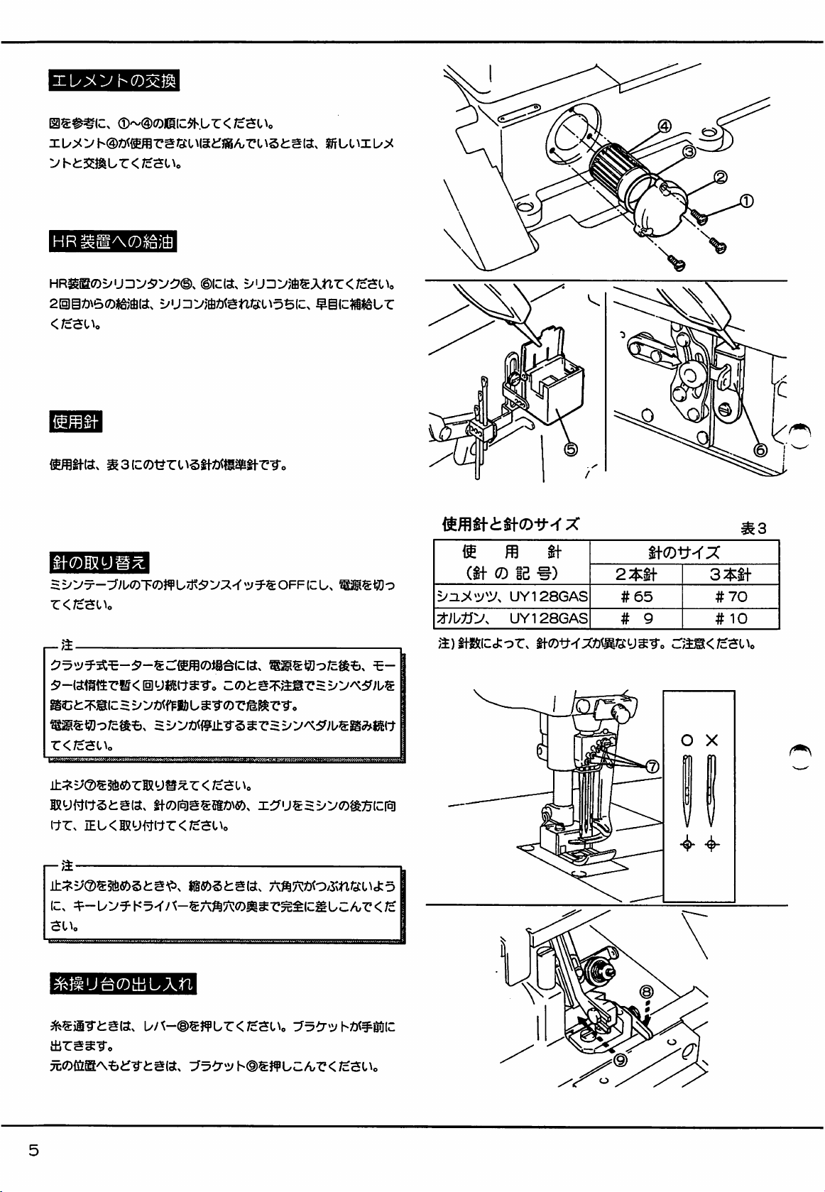
(S)~®o)(iicsgi^^sffiyf^(tr</cSUo
lif^^oiiiEiaTiBog^-ceor<
;cso^o
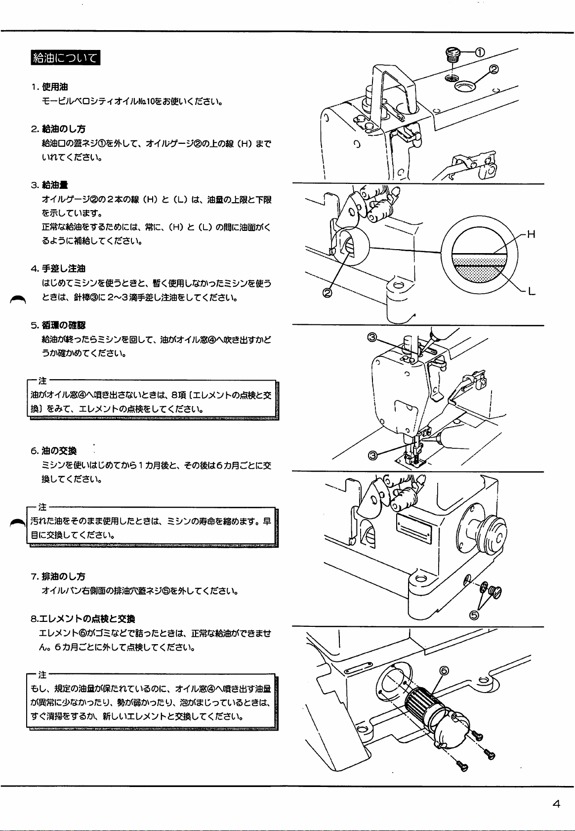
1.
Ho
Z
^;uh(a.
3.
=F-s-y-u-[t.
U-®)g^^33fi!t^
2M550W^il::75':/5'^-5'-Sa3mi<;cS
Ml!V^Uhg33<iH</^SHo
mt)\s^vy(DMmL{Z'^':>m^mo)y-
</cSHo
O W >/U-:3:
O
Wim
O
WiMt)^A7mmWrF(D^-:y)\y(Di^^[t.
/cSl\o
^
w500=^'j-a(7)jgM(a.
UT
50mm
^-To
^uiiircCtrOT^r.
ci§).
V(C(a> ^ SOmm
as
[259001]
fS^mt^WV^o
gc:ax0±,
(D'T-yil'%
z:$\m<
=E-S-y-U-<D^
(s.p.m)
6,000
<
5,500
5,000
4,500
4,000
60H2
120
110
100
90
80
(mm)
50Hz
145
135
125
110
100
C2)
r
©-©
Page 6
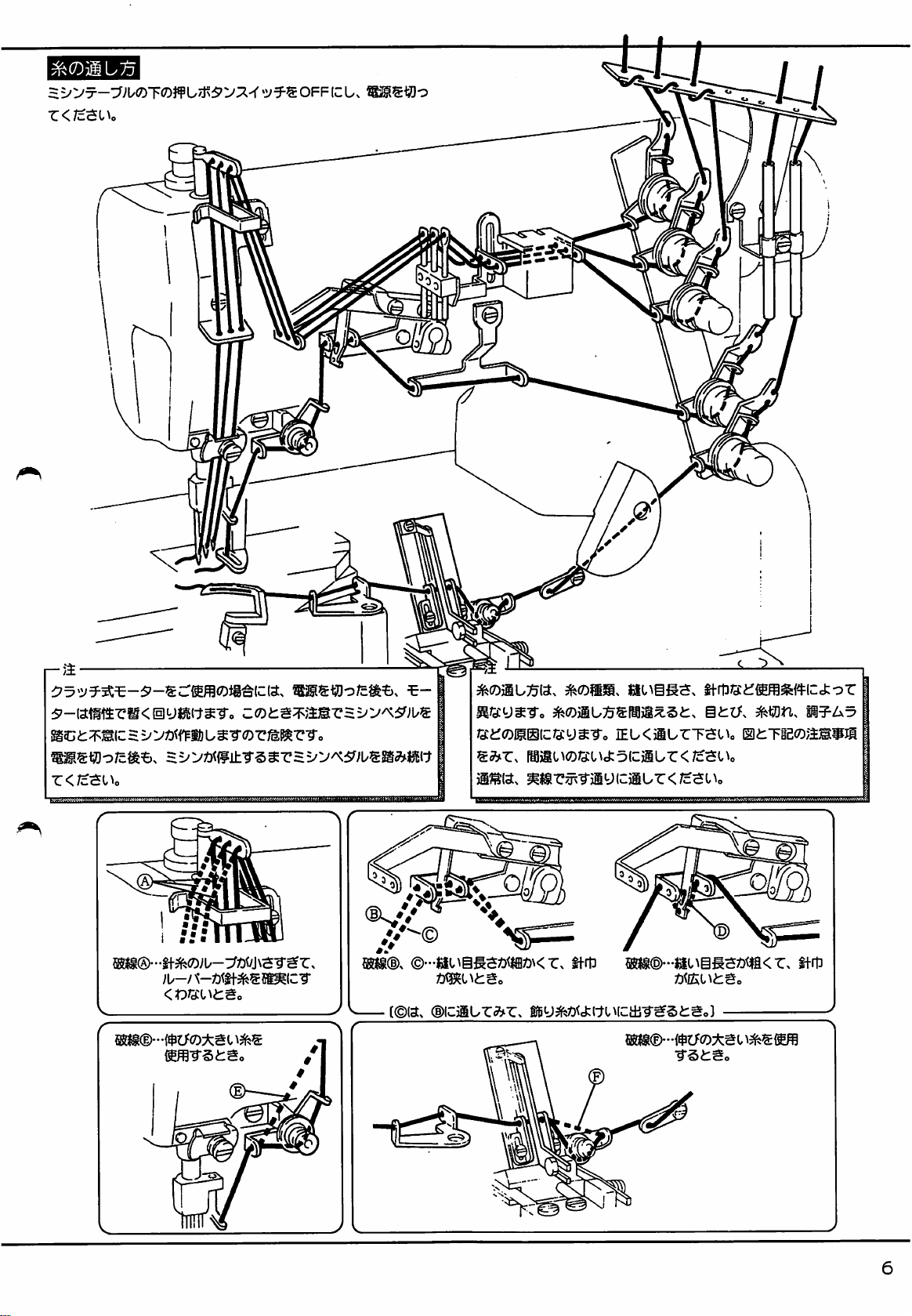
1.
sixyf^(-jr<;cSi^o
2.
ctoic.
t-5?-o^ssiSg0ur<;c3Uo
vyo&ixij^
urx
3Kj2cm
^;uhtiyt-®
<r6u^yL/SZ)i;coc
ai'vroiiesraia,
=^V®0giS!
a2(c.
33MI
r-a
mK/cSl^o
JBs:slJ®mlIi£ago1^rl^^■ro
\±i-f
I\tziz{,\m^
^oJB^(c^o/cI^llEl&r33m^<;cst^o
i^-u-fliovsar,
tl-OT^X
^1
^^6ii^/d:^-5'-3^-u-SJg^^33
siayrT.
at^ggsrcCiTfi!
?f^s:sy^S0iEa
m
W562 - 01
W542 - 01
W562 - 02
W542 - 02
W562-03
W542 - 03
W562 - 05
W542 - 05
W562 - 06
W542 - 06
W562-07
W542 - 07
(s»)
n-
2M\-
o o
o
o
o
o
o
o
o
o
o
o o
o
3M\-
o
o
o
o
o
o
o
o
o
o
(s.p.m)
6,000
6,500
6,000
6,000
6,500
6,000
6,000
6,500
6,000
5,500
5,500
6,000
6,500
6,000
5,000
5,000
a)MDSiS(ifZso2y«S)^j5->via,
a)ifaicj:o-c.
iHiea0ffi®sjB3a)^39ysTc
aais.oooserTo
c:a3B</csUo
Page 7
1.
2.|gjffl0U^
l\n■c<;cSl^o
a
f&mm
7^^)lCt-V®(D2:$:(0t§i
;UNalOS33®l^</cSl^o
zi^^)\y':f-v®(r>±(r>u
CH) L (L)
(3.
;fflfi(^±iJgi:TPg
(h)
lE^'XiliSJffiS-rS/cfi^XCia.
5d:olc?iiSSUr<;c$0^o
4.
i:g(a.
5.
€90!)ISiS
'Dimnsbz<rz^i\o
gft$@ic2~3/i#iiU/:ijfisur</cat^o
r-a
;W:^^;US(§K\oagtl3S/d:c^i:g(ax
m)
6.
^ur<;c$Uo
IL/;<yhOiis^^SLr<;cat^o
i-a
^IC.
(H) t (L)
8ii
(7)Pi(C;i®Z)K
gic35mLr<;c5Uo
7.Sfa©U75
;U/OaM
axb^vhO/iStttSSSi
XL/^^'
^o
h©Z)<U5Q:imSo/ci:gia.
6^j^c:i:ic^hLr;iS^ur<;c5Uo
r-a
Bu.
^S(^aa^^{s;cnrt\§0(c:.
^<'?«j§®-rst)v
y©® ^ U r </cSt
iE^G:i!iS)ffiZ)<rg^ia
:i--r;u®@^oasits-^;Sfi
i^uuxu^:yh^::2:smur<;cSt^o
Page 8
t
fi
m
H
0.'
r
y
rr
T
Xt
?
n
0
T
®
m
r
d
A
3
fit®fU
n
r
d
fit
nt
jmi
<-
d
08
0
<-
A
o
rx
<~
rr
08
d
9+
H
r
y.
ami
3
Vi'
H
is
w
i
D
3
1
i
3-H3
m
vj
V
v:'
nt
@
u
d<—0J
r
s
iji
3
IS
fit
?l§i
^
w
aii
I
v:'
v:
ill
d
A
u
fit
fU HIc
»
W
[T
'
V/
Vd
@
M
i
w
Ci
w/
c
(W
«
SJ
A
v3
Ht
t
u
V.'
EB-
fi
d
®
^
I"'
m
o-'
d
«
A
JflF
(V
8
}1
??5
t
fi
0
;5
M
Vi'
¥
fi
s
y.
v3
vr
4
v:
✓
rj
9t0d
-<
c
-<
c
4
ulo
N)
CO
lO
00
3
CD
(7)
H
M
A
4
8
>
(/)
CO
>
«}
0
VC
i
H+
v4
[A
1
A
CO
m
OF
^
n
01
gt
,
■HE
d
vc4
t
Tl
Tl
O
ri
fi
c
Ft
a
■)>t
rS
t
fi
s
0
w
e>J
c
d
c
rr
w
m
A
S
3
v::;
a
d
^ji
;□}
A
d
n»
rit
A
t
fi
m
rit
gg
C
c
m
o
5
s
^
t
H
^Ot
fi
v_
III
ri
3
m
°
I
t
U1
Vll
i=F
n
-H
c-
01^
t
fi
d
08
B
^1
3
0
I
«3j
9tf
m
fi
r
rr
«4
>
v:
08
o
CH
s
w
rc
&i
T.
CX
VJI
fv
m
A
08
m
or
&i
9+
s
t
I
fi
>}
t
1
fi
d
r
vr
U
cr
0!
>
ri
stn
3
nt
rn
A
t
®
fi
g
&/
>}
ri
HO
m
m
n
c
Vr
u
or
01
6^
fi
r
7"
nt
A
d
01
nt
ri
?-
/\
||
n
»
ra
48
<r~
m
0
()
Page 9
i
m
aa
I
v:r
vd
sg
d
l+f
VJI
1
et
IS
A
MA
vr
9+
i\
fS?t
fit
sSt
c~
P\.
F$
|D|
0
O
r+1
d
n
fit
1
m
III
Vd
A
V.'
d+
m
nft
d
i
•>^
v4
d
III
t
m
H+
fit
fi
0
VI'
III
d
o
(^t
C«
m
1
rH
*
t
fi
m
a
a
9?
:iia
rc
t
fi
gi
m
gi
c
a
d
w
c
9tt
9L4-
ri
£»
a
*
g4
a
5Hf
«
e
9?
a
vot
d
$11
bt
Mlfl
gs
c
vc4
gM
at
t
bt
fi
W
0
c
ri
01
n
vC
g4
m
<-
an
Ml
Or
cyj
£5
A
d
c
A
m
d
c
fit
A
d
c
*
"H
fit
m
QQ
01
m
9?
B
(\
c;i
fV
m
o
O
o
0
t
1
fi
H]
c
III
'
fl
<-1-
m
V
a
n
4
m
r
w
ri
m
Q>
o
fl
a
(V
«4
d
s
9tt
Ft
oj
I
nftis£u
rrs
cr»
Page 10
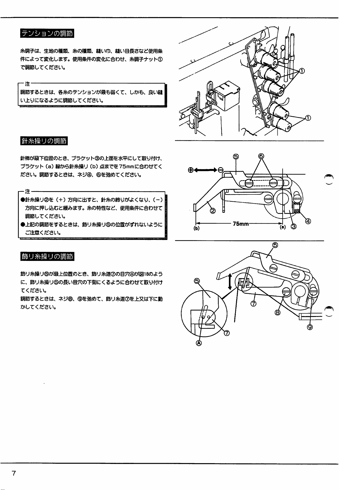
3
VCDlilD
zim\^z<iz^{.\o
r-'^
IS8i5-r3i:g«.
I
^± y IC/3:5
=&^(^5rV=^3V»t®=6^<r^
ct
5ICP® U "C
§f^^ucoiii5
y3Cr^u h (a)
/cSUo
r_;j
•ff3fe}su@®
:?5(^(c:}¥ua,ct]ige^s-ro
pieur</cao>o
•±igoisii5g-rstgia.
am<jz^i\o
«gO\6tl-^U
:f^m
(+)
:^(^lcai•r^:^
ifBu^^u(i)0{jigZ}<-rn/3:ud:^(c
L»\=&.
</cSt
^o
h@(7)±®®7j<5p(curffiy(^t-^.
(b)
jjSSrS
©®§fi«)r<;cSt>o
ti-M550«Byz)<cfc</3:y.
75mm
IC^*Dt?r
6!fflifewc^t)i7r
<
c-)
75mm
iU5fe}iuroisi5
®BU^U©/)^®±ia@Oi:g,
ic.
iifiu^}iiu©<Dgug7toT«ijic<5ctoc^TOraRyi^ft
r<;cSl^o
Siii5T§tg«.
Z)\ur</c^o^o
lrBU^)i®(7)g7^®Z)<iai80ci:5
g$u^)i®®±xiaTic®
Page 11
PI5"9"Si:g(a.
:^V(Q>^^6bZ<1z^l^o
1
:^V®(D^iOit)\e>m7^^ii:\^Z.
k
liSB'TStgia.
C^o
!i@0^si:sia.
R[AT{zm\LZ<1c^{,\o
r-m
(fSi:5fi5^*-^-ro
ff^lt
^v®.
©.
®5±ic^(-j'5i:.
^(D!ffttic^t)t?riig0L.r</cSUo
®.
®ssfi(»r.
(tu)
7.0mm(C^tDl?r<;c3l^o
tf^ji®S±XISTICii)Z)M^r
©.
®s±
tics
S(7
(Id)
®iasijsiij@iu^-ro
i;(7)li®
iiji-^sii50r>
MTStSISs
L/r<;cSc\o
(a)
it.
:!fcS(c^*Dt?r,
•css/cl7^^■(cifi-::^(:^rIxy^^(7r<;cSl^o
Ty®S§ftfi^rti-S(t
i^m'i^^-Xlz
(Id)
®=£ld3^«^(Ci!}X)\
(id)
®
(i)
8
Page 12
;u-/
rU/c;i/-/X-3l^<.
SJ:5(C^tDyr<;cSL\o
:;^y<Dg»r^
T^»U®
(2:$:tf)
(a)
iS;t)>6JU-/\-Jfe«^nS£Sf$tMOfflll
•••;i/-/^-±®;t)\6%^rTKUmtSo
ii-j
T^u®Z)<;c<ryc^
T3i5i^U®Ca)
TM!5^u®siiur</c$Uo
s/c
2:<^f
3:$:if
6.0—7.0mm
5.0—G.Omnn
\
(3:$:gt-)
^l-5>'Via5.0~6,.0mm),
^t)1?r</cSUo
^K)Z}^ur<;cSl^o
•"yU-/\-T®S"CTISIU;ci:So
h(i)<7)±®t)\6yU-/X-^g(t@OT®^'CO®RiS
[2:$:
6.0~7.0mm)
2*«f
(C
3 * if
hoo^uaic,
<;c3l^o
pg0TSi:S«.
r-fi.
s^^<?3:y^To
3feii©.
®!g§fi«)r</cSUo
ur
</c^Uo
®(Dg7^g^tDt?rBRy<^ttr
Page 13
H
w
m
d
VQ|
nit
exdfx
d
^-
s
c
fit
ex
a
nit
w
*
n
m
m
H-
v2
T
©
t
{Li
fit
IT'
ra
c~
d
at
t
fi
3
d
r
fit
fiO
fU
v:i
<r^
m
0
t
fi
©
d
c
IT'
m
d
:s
ex
s
IS
fit
C"
m
0
/\
>&
fit
A
U
vf
r\i
t
fi
n
tft
m
v£
3
d
t
fi
-7:
Vi'
P
EF
r
S
Hr
III
$f
P
@3
d
A
9i:
Vd
>
''
tt
Vd
m
1
QU
1
Q
t
fi
1
P
t
fi
m
)t^
QD
m
Q>
PF
m
n
i@
Kf
*
c
$?
/\
%
>
91t
c
t
Vd
v:
fi
©
<r^
ri
s
©
n
9t
fx
^
ex
P,
B
S
«4
a
D>
IS
3
c
©
c
m
en
\L
IT'
0
fi
r
CJ
ct
d
:::
'
3
□>
St
I
T.
A
fit
m
54t
rlt
fU
/\
vr
-K
$f
A
54t
c
"
^
tJ
c
d
9tt
«4
i^t
fx
*£4
A
QD
U
Or
m
c
m
V
9f
-7:
a
©
V.'
©
Vl'
U
V;
c
fg
m
m
i+f
$
9tt
(Jk
_j
rS
U1
o
(P
(D
Page 14
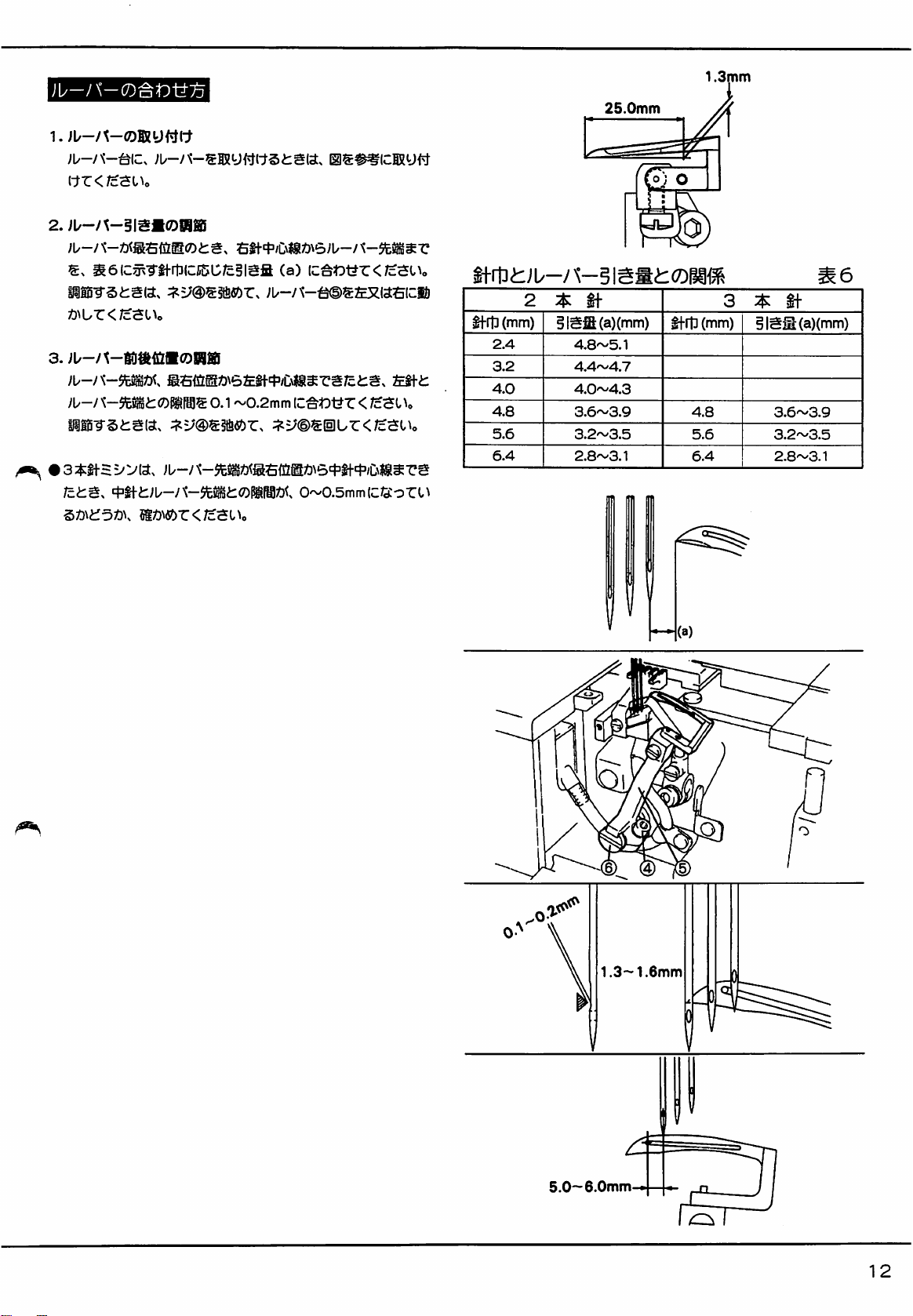
7X±^»>6
ic.
mics
ssfizE»\6iE§f=|3/C\i®^rs/c^s«,
1.3~1.6mm±icsr.
~0.2mm
T^urs;c£Sf
1.3~
1.6mm
io\e>. fc^4'/C\|g^r5.o~6.0mmic/3:§«j:5ic;.
/
r <
/cao
\o
lf-SSi:yi/-
§fraS®iSi5
OC
5iz^Tiirtiiz^otcm^iofs^J:o(z.
^l^c.
1. / \y
K^v'f-^uosiiiur.
2.
rt]
(CIS
L:
/ciiSIC^tJ-HT < est
r-;i
^fttSiaoPSDSTS^gia.
ftt:Og||0^SI2l(^«i:5(c;. M (b)
>/\yl<An-i'-;i/(i)0<PV-^>i:^t^0]®/)^-i5iU;ci:S.
TieoMfir^ot^r<
ftt$®±x«Tic»ur.
fH^eSCf/cfcS.
SJ9^1C^r31?r<;c5Uo
JsC
<
/c3t\o
ft^^ftTv:^:
fc
ft
ft
5.0-6.0mm
rsr
(a)
ft®
£ft®$
5litf£
ft®
(mm)
(a)(mm)
(mm)
(a)(mm)
2.4
10.2
3.2
9.8
4.0
9.3
4.8
4.8
8.9
8.9
5.6
8.5
5.6
5.8
6.4
4.6
8.1
8.1
r
wMM'//////////mmz{
1 1
i o
1
(b)
O-gj)
Page 15
(tr<;csi^o
2.
JU-/X-§IS«09ia
1.3mm
25.0mm
aeiCg^TlfrtDlccSC/cSISfi
na-rs^ss.
^M^r</cSi^o
;u-/
TO
^5i:s«.
/ci:g,
^ntL'DtiK
^5;@g§fi«)r.
0.1
(a)
;u-/^-^s£x«sci&
~0.2mm
IC^WC
:;^=;®®(iur<;cSUo
0~0.5mmlc/S:-oru
<
/cSO
tf
rtD
(mm)
2.4
a2
4.0
4.8
5.6
6.4
2 :$:
§ISS(a)(mm)
4.8~5.1
4,4~4.7
4.0~4.3
3.6~3.9
3.2~3.5
2.8~3.1
If
^rt]
(mm)
4.8
5.6
6.4
(a)
BISM(a)(mm)
3.6~3.9
3.2~3.5
2.8~3.1
1.3—1.6mm
CO
5.0—6.0mm
12
Page 16
tfgc?
(a)
RJ:^0N6HTIc:<Sci:5(C.
IV
issi5-rsiis«.
r</c3iv
yi/-/
K-$t^i:(7)MZ)<0~0.05mmlc:?cC5cfco(C^t)yr < /c
stv
=1=^c»3/C\i®^rs/ci;gia.
:;^5;(Dgst6«)r.
thStt®s±x«Tic:i&^^u
O-OSmmgiSo/cSS.
S(t®Spgi5Ur</c3Uo
ur<;c5iv
ig/)<agi-o@
tf
taor</c$tv
jMUffi®liS®iSli5
8~1,0mm
/cSlV
<;c5iv
jn u ffi
3^u®Z)<s±{a®sr±#U/ci:g.
isai-rsfcsia.
2.
:^(DgJSSffiy.
3.
4.!ii07^{ch'5'i'/\-smuctf^*.
(C^t)t?r < /cStV
0Su± y fuT y ©HIS
Tie(7)^Tirs®S5ur</c3Uo
(3^:)
:r^y@®3fifiOr<;c5Uo
®mu"c<;cscv
©s»T:j^uffis±xaTic®Z)\ur
:;^=;®g^ur<;c5Uo
TO
5tM:;^y(D®^gBSor</cStV
:;^=;©giiur,
0.8—1.0mm
®—'-
T
/'^
0.1~0.2mm
©d)
^55
•:;^y®gi5i-ri:,
^cy^To
iiS^J3:i:c5r:i^y®€^g<;or<;c3iv
i^-r
()isufflo®soiig0]
iu±y.
®ur<;cstv
^/siagtiTyic
13
Page 17
1.
8.3~8.7mm
wrstsia.
(ciS75\ur<;cSL\©
"C?"©
7.3^U'i'5?-®s_h52aT
Elc^ctoC,
MlCjib/ci^Sia,
sJ;oic^wr<;cSu©
SilEiTStaia,
6.
1.±g2c?DMI0S-?Si:gias
£2+t(7)M^^0.5mm£7)^5®^iiiSLr,
S$ft^'/i:\/3\63.5~4.0mmM®Cfig-r
^v@i:©SlSSg6^)UT:.
T^-U-SDLJXti^e.
sss®,
u©
X3\^)\6m\i;Sia,
;S®e5.0mm^C^^Cl\Sg£/\-r6L..
■enrsaa.
(c.
;^:?b':^5^-0jiyfi®^<ur<;csu©
:3.:7L^':;5?-®(7)fi''JSia 1 6mm
WTstsia.
^.J>-h±m^$hl..
Z<Ic-&i\o
2.
:h':;S©^»,
Tt?.<Dmnv^mz<7zzi\o
^i^-vmissBSor,
a^:j®%±RUT\zm\\^Z<Jc^l^o
®s
17.0mm®S^?d:ii?i®
r-r©
E£to
U/t-©^[5IL«M
r < ms
IfB
1.0mm
0.5mm
\
mmmmnMi^^mmmm
0.5mm
1J
8.3~8.7mm
ca)
PISTSi:3(3.
(7-C</£3Uo
MT§t:3(3.
1
.OmmlC^tOt?.
:i^y®®!fi(St)T:<;cSUo
gp^ifeu^
g7^^HIEffl(Cfgi7rSSy^^
3.5-4.0mm
16.0mm
^
Page 18

}¥x5±(f/ci:g.
lC5^Tfl5iCIC^o;c^^lcO:5«J:5(C.
Sl^o
i.^^-u-smur.
iiiuffig®T{5i®^rT-c<;cSt\o
Tie<7)^fi"Clll8i5Lr<;c
(a)
mi
a
4.±iB.
J:olcTOUr.
}¥x®gj&iC(c^o;c^osasr±i:fr<
•±':;h@S«5fi?)r<;c$Uo
Jf5^sij}¥x±i:fj
W562-01
W562 - 02
W562 - 03
W562 - 05
W562 - 06
W562-07
a)
fHSlCctor.
/'SiiK/cSUo
}¥X_
7
li-|BJSyJ9x±l:fS(mm)
2 :$:
6.3
6.3
6.3
5.3
5.3
5.3
§f
3
5.0
5.0
5.0
5.0
5.0
5.0
^
L":/5^-ro
iBog?ir^*3ttr</cSc^o
1.P-A±M®^hU.
r<7cai>o
2.:i^5;(2)
(2:$:)
5*-f s V
:|^y©®J£Sffior.
;lS(-J®5miC^6L
±ffiO^l^ED©tx^teV0^l,\ED®
15
Page 19

Z)<Sf(7)S{|iJg£^i&<K=6.
1.
p-A±^s^hur<;cat\o
2.:^v®
9^l\yb'=^v
r-;4
(4:$:)
(±)
®Ol2':/|-{fl®S-r6Ur</cSt^o
a:^h*/!fx-r-;K®glslUT:,
(±) (+)
r;u-/s-|fi^op|j5j
su;ci:g(a.
2ESfaM
iJlc-rs^i:,
ti-M
(Si-|$i:;u-AfcSaii!}
4
q:
fc
sj
1201^155
ti-^±T3iifllcWT5;u-/
®(c^t)t^r<;c^Uo
Ur</cSl^o
^-i5^3i®ro5'-r
Ji^^y<^(o^i\^©^03yoyvy
S^'::?(^!SS0«.
h(73^t\ED
;u-/x-Su^i
;i/-/'^-Z)^;£^$!j<K(ciati-(7)g{ijgiiiaUx
3)
(c^wc.
Ti2<^^fi-cpg0ur<;c$o«
a^ifi<
B§ic:(aii-(7)
^
1.
-fv
hOSSfifiO.
fi
ic^t)t?r<;cSi^o
y^To
^;i
•±i2(7)Sili5SL/c^g(S.
silsur,
!ili5:;^y®SIslUT:.
s>^^yxutnx^\^t.B\t.
tfo+t-raic^o/clu^
s
m^Lz<ic^i\
16
Page 20

tMC^lU^W^To
St^o
lS0Sg/)\6Stl-^rg-SOrtJCJIl^^-ro
pasTSiisia.
<;cSUo
:i^=;(i)e§fifi?)r.
m^i^@®£X(as(cii)Z)\ur
ff
x®iu±yM
W500-05IC®fflU"Ct^SffXia.
}¥x(§)(7)|fi±yfiZ)TO-cg^-ro
Uo
t&m^axnu'DZ.
PSS-rSi^SO:.
zsixpmm^^ix-Xic^^jmro
:^':y
h©S3tfifi?)r^
zSlxs
M\W3:t:<DW^P^^[Z
}¥x@(^^|fissi-fr < /cS
:;^v©S(lIUr<;c5t^o
17
Page 21

ISor.
f-a
5^uc^±;><;^SIRyms^:g«.
tf
irUU±x::^t55mur</cS0^o
5^
Uff
^0(tr:i^v®S«gmr
</c5Uo
2.3/-u-^iiur.
3.
±T><;^t^p^(c^sAn.
<;cSUo
Tx::^ro3ca
2.
y39t^i^Wi±mtmcu^[z^t:>tiz.
;c^l^o
3.
±Tx;^op^ic^sAn,
r</cso^o
T^::^QJe6C1!
±x:7.®gT{LZ®^rTi-/x
y-^j--^mi>z^ymn^wy^i^z
:i^=;®s§fi«)r.
3^-u-sisiLr.
T>^ym^uz<tz^i\o
T><;^(0)ST>t^^®o3l(c5u
Tx;^i:±x;^
0.5mm
n
^vmmsbz<
x;^iions{iZ)\«)
siiBs
S-S(7)rt]|cm§/cfiOlclig0U^-ro
^
l,^o
Mm</)m^rd:^i&mwumz.
:^y®i::(B^^(sbz.
Txy^©^<mizmk).
±><:xs©HxyMwssropiS
^t)t^r<;c^^,^o
iiS0-r5i:sia.
7.^®®±3^(aT(cibZ)\ur < ;c^t^o
^m^e^ymmmz
msis^v®^^uz<ic^
sic^y^-^o
^50.5mm(C^^5J:5lc
±x
18
Page 22

u
fit
nit
>
I
9tt
n
u
I
ri
5>tt
m
3
U
I>
d
<~
m
C
3
fit
a
W
c
>J
Rt
t
(X
£f
fi
C
ff
LIM
'
a
n
(X
d
3:
u
d
Vi
^
v:i;^ c
t
fi
t
fi
a
t
fi
A
>
01
v:i
d
A
Rf
fit
vj
®
(T >Jd
n
'
fit
m
v_
m
m
c
d
<—
m
o
(X
@
t
fi
C
^
3
(H
vc
^
d
t
^
fi
^
s
o
n
91-
>J
'
d
M
□>
fit
A
n»
©
t
\L'3k:
fi
III
*
rN
«4
O
I
U
'
0
3
On
C
I
t
fi
5
s
^
c
m
o
c
Ff
>J
(X
w
SS
t
fi
Oft
fit
fx
d
(W
9?
IS
3
S
□>
c
d
9+
3
@
I
ri
ys
r
01
o
Or
MA
n
01
ut
t
fi
a
□>
®
fit
Ot
n
c
°
O
S
A
M30
(X
01]
-HD
(It
t
fi
S
c
n
0);
c
i
fj
c
B3-
□
m
OJ
vi:
I
c
c
^
m
fit
I
r
a
t
yj
fi
>j
3
s
yi
a
§
-jj-
3
In]
vi:©fi
>3
d
C
t
r
d
t
®
A
d
fi
nft
d
d
m
A
fit
□
n
O
u
a
®
Or
f»
vs
^
d
/\
d
§
rl
9+
^
^
VI
9+
d
Q>
^
cf
'
A
t
fi
3
m
fit
c
°
Sg
s
5
w
>J
©
21:
a
^
^
3
fit
>^
c
vC
»I1
II
m
"H
3
n
U
w
rr
m
<-
■
9?
m
r-
T
)<iH
n
(X
3
ll£
m
"H
U'
(^
vO
Page 23

irac01XyWltffiB®lSli5
dfAi:glSSSnuiCi^U^t)t?§<t5lc.
(DwnvmBLz<tc-ai^o
[i]
^¥XC^^L^rl^S^^-1'
:b'^h'©(c;eorjiiyi^.^n§iTA»^.
/cffls^i^yiz^^nscfcoic^otjr
r<;cSl^o
[2]
9g(^©x
□-3-®iCctor.
Ts
rti(c^t)-HTaxyi^i:rr
WT§i:S(a,
^
paLr</c3i^o
Is]
pa-rsi:sia.
aur<;c5t^o
©(Dia
ixyai5n/cifAWx(^:df-r
iE5icgfit)M®'\jiiy)i^nSci:5ic,
®0»a
k
@ia,
D-^-®,
:iE?$ic:
ASfassicBsy
irArtD|c^t)y-CTiB
K0Ha
msiP.
</c5Uo
13^
M©S£X(SaiCi@ffiU
<
/cat^o
®(?DF^g3ii@L/c=rAZ)<,
{^cj-c
</c^Uo
sif«3®.
aiuiiiicjsu
t^©rao
sgp^g®.
®®&5^ias(c:p
©sita
©s&xiaac
?lF«3@i:
w
©
iJAi^y
d'Ai^U^^<?DS:$:6^/3:j^yttlUfiia.
^To
jj]
«ima^02iymus0sa
^
wrstgia,
(+)
i—ji
±ie(^m;c(fc.
^=Tyi>3V(r>mm\
tij
</3:y^-r<,
L/m
0.9~2.2mmOaSrWCSS-ro
h®s§fi«)r>
Scti\jiiyii}Lfij!)<'#6n/eCUiigia,
=&f?fTO7or</cS0\o
TiB(7)2
iia:i^9®s0Lr
(-)
{sijicm-ri:.
21
<;c
'j>
m
20
Page 24

2]
4$glJtta^0]2IUUUS0na!
i
A^3.5mm(r>mmvmmTBmto
sutt^iciny
vmmuz<tc^i\o
'\.iL^\2y(S>(r>±:^v®
2.
:;^5;(D(^if56Z)M
ni:oizLz^v:^v®^mi^z.
3.
ra
±i5(Z)!lli5mrv
bbBboinasj
h@s5ififi?)r.
(+)
ffl
ijicisl^t,
<G:y^-ro
:$:IC.
/wh^Tn-rjuDSKit^i^icioiur^
iliyi±iUfiG<^<G:yv
=&#ft?TOor</cai\o
tti
(2$)
mm^v®^m\^z<rc^i\o
g§fifl?)r<;c^l^o
^-bV5'®ilUC^"C,
T'vs^avroiffl®
x^i2b®s@$ur<
(-)
fJicu^i:.
Tieos^
/)
ms/ix
v
i!>
TlBx
dfA0ips^tJH(ci;5Dr5^b=/3b®slS0U^To
la.
Tstsia
(+)
U-;3,tF-f
h'la,
3!En®jiiE'rs;c«)(^g®rTo
g«oi:g(a,
u5b-:^®«iDtsia.
u-;^±r'f
i§is#%ic,
w^bmjssffiy,
Pa3:i^=/®®(g]Ur</cSt^o
ijic,
i§<-^5i;aia
H:
CLG210)
Kroisy
icot^r
^f^iysj/ttnic/ayc^B/cCL/-;^
'j><ur<;c5Uo
wit
®~@oi(i(cKyi^(tr<;cSo^o
(-)
E:tJS3S<
«iJ(c|diuz:<;cSOo
\^-:^<r>^mm
jtis«n«<S£Lr
21
Page 25

W562,
®#%icTig<^ii^rKy
1.
2.
3. / W
^'5^-
r>
:;^y®re£ur<;csi\.
•
W562-01.
•
W542-01.
W500=/U-a55^y(^55.
(1
:0.5~1 : 1.3)
02. 03.
02. 03.
f^itr < /cat^o
h®si5^)y\-(c:isy{xj(tr
h@S/W
ti\S
V5^-®IClRy|;}(tr
S
©IC:
06.
07
06.
07
±i50JB^(a.
(1 : 0.5~1 : 1.8)
</c5Uo
mVlEi
E
<;cSOc
0
ffl
®iEtfr</cSUo
r-;i
±12.
iEMi&a)^®siS(:f/c±g(s.
omym.
g|S#%(C.
vz:mm<ic^i^o
b/X-®(7)®)<i5
22
Page 26

(B]-[c]-(D]
mic.
5i/Vlc=6WS§SiO)it\S^'rEPi:Ur,
?
(IX
(2)
gMuru^"ro
§0(c^ijEDsnru§»^i:.
ms^^Zs
r<;c5ix
F^3lu<^^3:t^ct5lcl§^^Dt^•c.
5'^=:/::?^i/hogg^efiiZ)\«)v
^i'y(0±mt:T
tgg^sQiL/csao^
t-a±ms^l.
Tie(Z)s^r5smu
P-Zx®a5(CjK
t-Ix®
Sj
off
23
Page 27

2.
|§1S#%(C.
y
0
r-;i
Lz.
7-ix±m!3)tt'<M\y®^^Lz<jc-aL\o
:^v®
(4^:)
ISJ61
^r
§|gtsc^r</c^c^o
y\VK7jx-r-JU§)SKDo<
</cSL
0S#%(c;±':/h<i>>
1.
1§]S#%(C.
r-;±
•$as®®IXy
lESiic
Asfiigic^^^t?r < /csi
y»s«)r<;csu„
^hU/ci:aoi20l(l(c;.
K
©13.
Zf-U-@.
Itst
{gg0«?>
lD/'^-©^mk)mZ<Jc^L\c
:;^y®<z)$t®Z)rFiffi(7)f52®3^(s:)5v:ic
brass.
^o
^^i?®seg{titrz)\6.
boti\
3.
@®^KU^<;c^l^o
©i::®.
/c/cu.
6.
^yy(DM£D
o~@0iiict)/'^—®>
®{t.
^^(cj£giR6-ric§fi«)5;ci-jicLT:<;c
5''i'=vr:^^;uh<2)®^hur<;cauo
1
2
(B)
(C)
y—u—@.
m/c(^
s;c(3
(C)
(D)
w.
2.
t^-u-S0Lr.
rl!)»^ur.
3.
±B<Dn^UoJcmms
eD®s±ic0(-j.
:iT{il®srTr</cSt^o
$a§®(?DSi^ED©i:-iSrrstcsr
^^;i/h®sw.
c^r.
Tcii y (cix y ftit r <
-rnst.
■r.
2JlOTOSffio/c^^.
SOaL
^0]©^»<-ix-r s c 3 r
/cSl^o
(4:$:)
4.3^-u-s0ur.
^ssMz</c^Uo
5.y-u-^muz.
rpj
7-yt^yi<(D^iW®/)^-sibzust>\t:3AK
r</cSUo
6.0s#%(c.
tf^»<®±{5i®0ts.
p-A±^.
lllOct5(c:^;uh=^^v
(±)
®Z3<ia§©ic^5^r}¥U
ss5«)r<;£sc^o
/cs t b
(±)
5^ t a
:y
3Z)v
(fftyu-/
(lem^m)
t--i';i//r-y®5ixy{t(tr</cso^o
;^i:ic.
C±)
OSUED®il.
h®s
Z)Mt r <
ma-mmcDm
^-£505^^
/\yi<7n^-Mc^
ssm
5y
s
m
y
24
Page 28

C<^5'-1' = V::?S5i^lCiEU<^Ot?S7cfi?)(C, -tZfV
s-i^yw-v
ano
(#510-91)
®ffl®Lw^-rOTcr^ijffl<;c
mm
c^-y)
£SfiS$A
JU-/\-§«B
Cmm)
(mm)
WS62 - 21(356)
(mm)
Cmm)
(mm)
9.3
3.7-4.0
9.7-10.2
5.5-6
18-18.5
W562 - 21(364)
8.8
3.3-3.6
9.7-10.2
5.5-6
18-18.5
®
nX
25
auaaaF
ff
X±tf«G
(mm)
(mm)
CS.P.M)
1.2-1.5
7.0
5,000
1.2-1.5
^W>////////7Z7Z^
7.0
5.000
Page 29

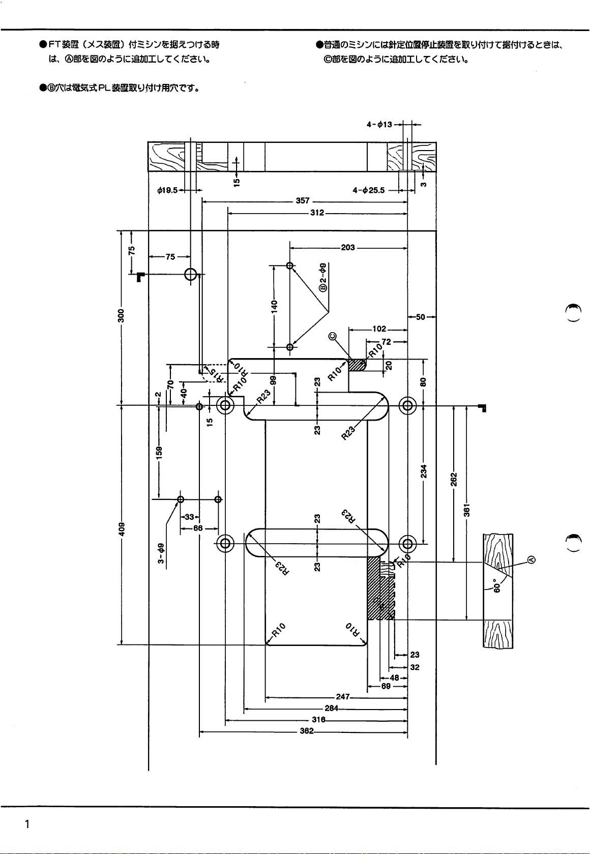
•
Add
with
I
The
the
part
FT.
hole
marked
marked
(A)
(B)
is
as
shown
provided
fitting
when
installing a machine
electric
PL.
I
Add
with
the
the
needle
4-025.5
part
marked
positioner.
(C)
as
shown
when
installing a machine
-33
►
ii
—48
27
Page 30

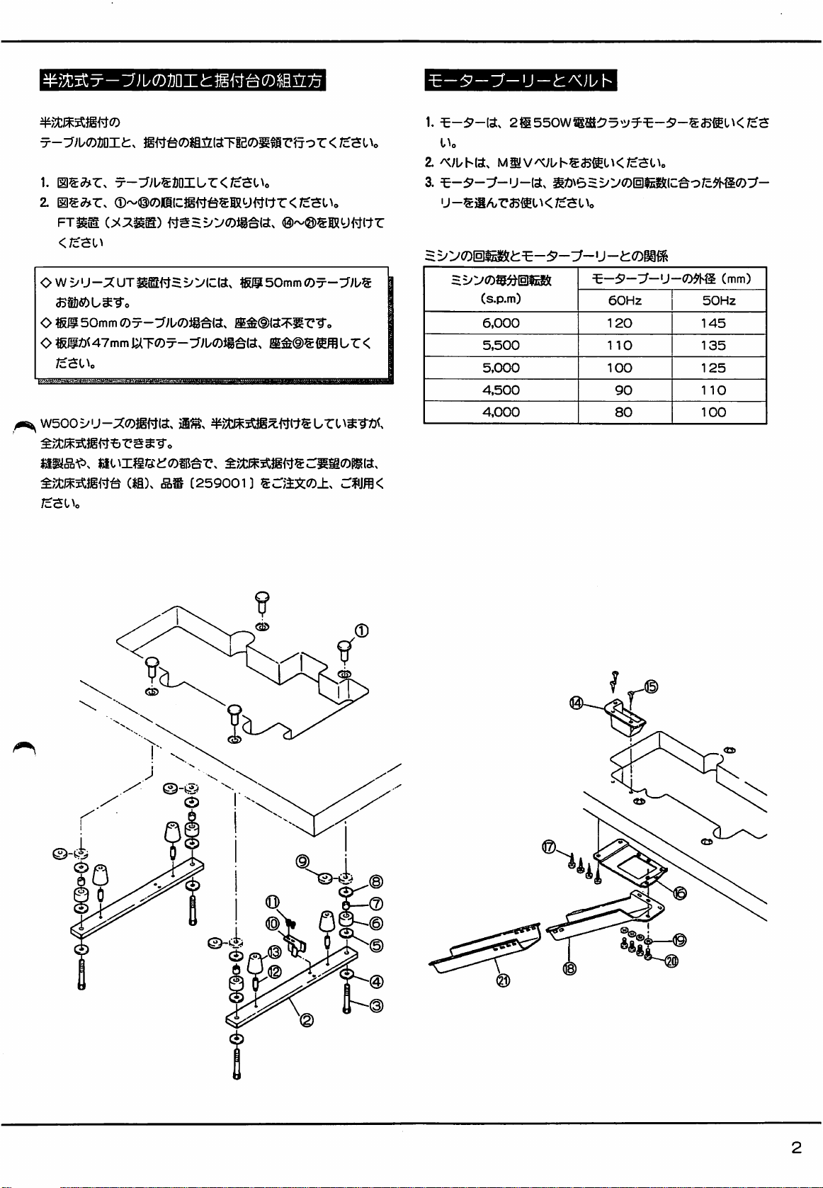
CUTTING
REST
Semi-submerged
machines.
Following
the
machine
1.
Cut
2.
Assemble
the
THE
TABLE
BOARD
the
right
FOR
installation
are
the
procedure
rest
board.
table
by
the
machine
illustration.
AND
ASSEMBLING
SEMI-SUBMERGED
is
adopted
for
cutting
referring
to
pages @ to
rest
board
INSTALLATION
for
the
table
®.
by
following
THE
the
W500
and
steps®
MACHINE
Series
assembling
to®
in
MOTOR
Following
1.
2. V belt:
3.
PULLEY
Motor
Motor
are
Double
Type
pulley:
AND V BELT
the
specifications
pole,
550W
M
Select
the
proper
the
machine
shown
below.
for
the
clutch
motor
motor
to
be
used
motor
pulley
by
and V belt.
for
the
referring
to
speed
of
the
table
O A table
O
O
Generally,
machines.
applied,
If
please
the
50mm
Washer®
Washer®
the
However,
too.
your
sewing
place
part
number
an
thick
is
recommended
is
not
needed
for a table
is
needed
for
tables
semi-submerged
the
articles
order
for
259001
installation
fully-submerged
or
operations
the
fully-submerged
50mm
less
than
for
the W Series
thick.
47mm
thick.
is
used
for
installation
require
such
installation kit
with
UT.
W500
series
can
be
installation,
under
Relationship
Machine
between
speed(s.p.m.)
6,000
5,500
5,000
4,500
4,000
machine
speed
Motor
60Hz
105
95
85
80
70
and
motor
pulley
diameter(mm)
I
\
pully
50Hz
1
25
1
15
105
95
85
r
Q
28
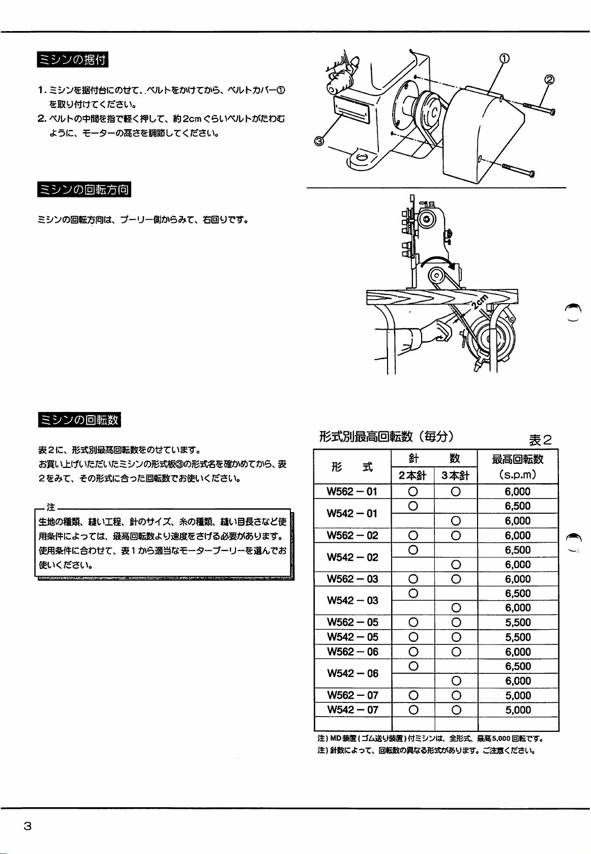
Page 31

BELT
GUARD
1.
For
safety,
machine.
2.
Adjust
when
Adjust
THE
TURNING
The
turning
machine
AND
be
the
tension
you
press
the
height
direction
from
its
right
BELTING
sure
to
fit
Belt
of
the
belt
the
middle
of
of
the
motor
DIRECTION
of
Machine
side.
Guard ® with
so
that
it
can
be
it.
to
do
this.
OF
MACHINE
Pulley
is
clockwise,
Screws
2cm
bent
seeing
(§)
on
inward
the
o
J—
o
MACHINE
Make
it
not
—
Note:
The
sewing
stitch
Select a correct
operation.
SPEED
sure
your
exceeding
maximum
conditions
length,
etc.
machine
the
speed
motor
type
maximum
may
such
as
pulley
number
speed
as
have
to
fabric,
operation,
size
from
with
Type
Plate @ and
listed
in
Table
be
decreased
Table 1 suitable
depending
needle
2.
size,
thread,
to
run
on
your
MAXIMUM
MACHINE
W562 - 01
W542 - 01
W562 - 02
W542 - 02
W562 - 03
W542 - 03
W562 - 05
W542 - 05
W562 - 06
W542 - 06
W562 - 07
W542 - 07
Note:
If
the
maximum
SPEED
2-needle
machine
Is
speed
Num
ber
nec
dies
3-needle
O
O
O
O
O
O
o
o
o
o
o
1
equipped
is
5,000
with
s.p.m.
of
O
O
O
O
O
O
O
O
O
O
O
the
metering
Table
MAXIMUM
SPEED
(S.P.M)
6,000
6,500
6,000
6,000
6,500
6,000
6,000
6,500
6,000
5,500
5,500
6,000
6,500
6,000
5,000
5,000
device,
2
the
29
Page 32

LUBRICATION
The
oil
was
machine
1.
2.
3.
4.
with
Lubricating
Use
Mobil
To
fill
oii
Take
out
the
upper
Screw
0.
Oil
level
Always
between
Manual
Before
idle
keep
two
oiling
starting
for
more
Bar0.
5.
Oil
circulation
Be
sure
to
drained
from
oil
before
starting
Oii
Velocite
oil
the
No.
Screw ® and
line
'H'
of
Oii
enough
oil
lines H and L of
machine
than a couple
check
check
that
oil
machine
it
for
10
(ISO
pour
fresh
Level
Sight
in
the
machine
Window
for
the first
of
weeks,
is
splashing
when
shipped.
the first
VG22)
oil
until
time.
or
the
Window
so
0.
time,
or
manually
inside
Window
So, fill
equivalent.
oil
level
reaches
(g) . Replace
that
the
oil
level
if
the
machine
lubricate
Needle
@.
the
is
is
—
Note:
If
oil
does
6.
Oil
Change
Change
After
that,
—
Note:
Be
sure
to
moving
parts
7.
To
drain
Take
out
8.
Oil
Filter
If
Oil
Check
change.
—
Note;
If
oil
jet
contains
replace
it
not
splash
inside
Window
oil
after
the
first 1 month
change
oil
every 6 months.
change
oil
because
and
shorten
the
life
oil
Screw © and
Filter © is
and
clean © every 6 months
in
Window
bubbles,
with
new
drain
clogged,
(g)
is
check
and
Oil
Filter.
abnormally
clean
@,
in
operation.
dirty
oil
time
of
oil
from
nomal
lubrication
at
Oil
check
Oil
Filter©.
can
cause
excess
the
machine.
here.
cannot
the
time
of
the
restricted
Filter © or
or
wear
be
kept.
regular
weak,
or
if
necessary,
on
oil
oil
30
Page 33

REPLACING
Refer
to
Fig.
Clean
Oil
Filter®
OIL
FILTER
and
disassemble ® @
or
if
necessaiy,
in
sequence.
replace
it
with a new
one.
SILICONE
Fill
Reservoirs ® and ® with
Do
not
NEEDLES
The
standard
REPLACING
use
OIL
any
other
needle
NEEDLES
FOR
is
as
oil
shown
H.R.
the
except
DEVICE
silicone
for
the
in
Table
3.
oil
before
silicone
it
is
too
oil.
low.
NEEDLE
NEEDLE
Schmetz
Organ
Please
of
needles
note
in
SYSTEM
SYSTEM
UY128GAS
UY128GAS
that
the
the
machine.
needle
AND
size
SIZE
2-needle
#65
#
9
varies
depending
NEEDLE
Table
SIZE
3-needle
#70
#10
on
the
3
number
Turn
the
machine
p
Note;
If a clutch
power
is
turned
pressed.
the
Loosen
Fix
—
When
key
IN
When
front.
To
power
Screw @ and
the
needle
Note:
loosening
fully
into
AND
threading,
To
off.
motor
is
used,
off.
prevent
is
turned
off
with
its
or
tightening
the
hexagonal
OUT
OF
press
replace
it
into
it
will
keep
The
machine
accidents,
until
replace
scarf
be
the
machine
needles.
faced
to
Screw
hole
of
THREAD
Lever
TAKEUP
(B • The
its
original
on
running
will
operate
sure
to
keep
stops.
the
rear
of
®,
insert
Screw
@.
BRACKET
bracket
will
position,
push
by
inertia
when
the
the
treadle
the
machine.
the
tip
come
Bracket
after
treadle
on
of
the
alien
out
to
(§)
in.
the
is
after
the
31
Page 34

THREADING
Turn
the
machine
off
I—Note;
If a clutch
power
is
turned
pressed.
the
power
Dotted
f
Dotted
motor
To
prevent
is
turned
lines®.
line®
is
used,
it
off.
The
machine
accidents,
off
until
.When
not
threads
small
loops.
TT
.When
threads
will
keep
be
the
machine
the
catch
needle
the
on
will
sure
looper
the
because
stretch
are
used.
running
operate
to
keep
stops.
does
needle
of
too
thread
by
inertia
when
the
the
treadle
Dotted
after
the
treadle
is
on
after
lines®,©.
(Apply © if
r-Note;-
Threading
thread,
Refer
to
Generally,
.When
the
is
fine
and
gauge
narrow.
the
spreader
depends
stitch
length,
Fig.
and
pass
stitch
length
the
needle
thread
on
the
needle
the
following
threads
as
Dotted
appears
too
Dotted
sewing
gauge,
remarks,
shown
line®
much
line®
condition
etc.
and
by
continuous
...When
is
coarse
needle
under
®.
]-
...When
threads
such
pass
threads
lines.
the
stitch
and
gauge
the
stretch
are
as
the
is
used.
the
length
wide.
type
of
correctly.
32
Page 35
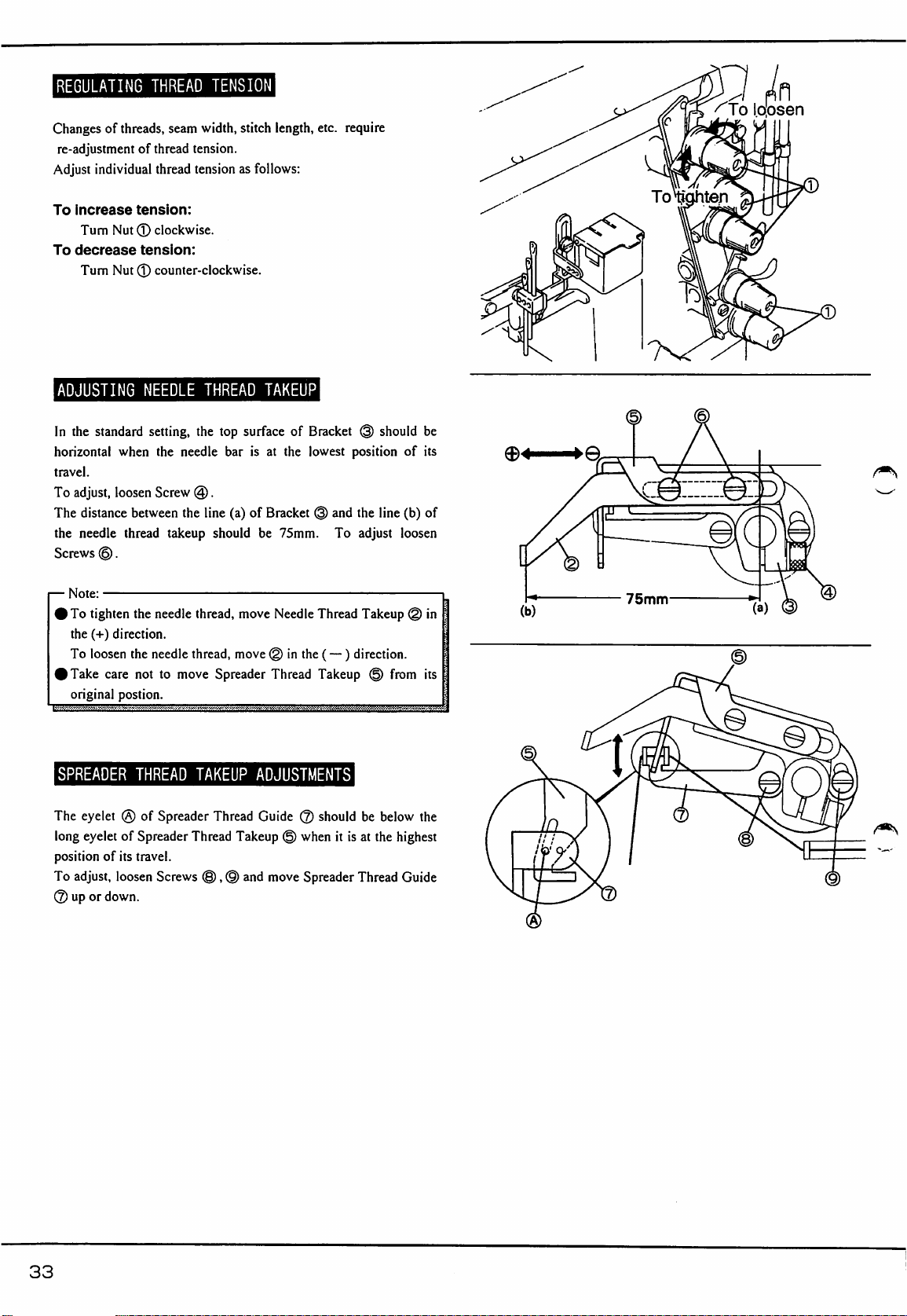
REGULATING
Changes
Adjust
To
To
of
threads,
re-adjustment
Increase
Turn
decrease
Turn
of
individual
tension:
Nut ® clockwise.
tension:
Nut ® counter-clockwise.
THREAD
seam
thread
tension.
thread
tension
TENSION
width,
stitch
as
length,
follows:
etc.
require
^To
Idosen
ADJUSTING
In
the
standard
horizontal
travel.
To
The
the
Screws
—
Note:
I
To
the
To
I
Take
original
when
adjust,
loosen
distance
needle
©.
tighten
(-I-)
direction.
loosen
care
postion.
SPREADER
The
eyelet
(§)
long
eyelet
of
position
To
©
of
its
adjust,
loosen
up
or
down.
NEEDLE
setting,
the
Screw
between
thread
takeup
the
needle
the
needle
not
to
THREAD
of
Spreader
Spreader
travel.
Screws
THREAD
the
top
needle
@.
the
line
should
thread,
thread,
move
Spreader
TAKEUP
Thread
Thread
©,
TAKEUP
surface
bar
(a)
move
move @ in
of
is
at
the
of
Bracket @ and
be
75mm.
Needle
the
Thread
ADJUSTMENTS
Guide @ should
Takeup © when
(§)
and
move
Spreader
Bracket @ should
lowest
position
the
To
adjust
Thread
Takeup
(—)
direction.
Takeup © from
be
it
is
at
the
Thread
of
line
(b)
loosen
below
highest
Guide
be
its
of
in
its
the
75mm
33
Page 36
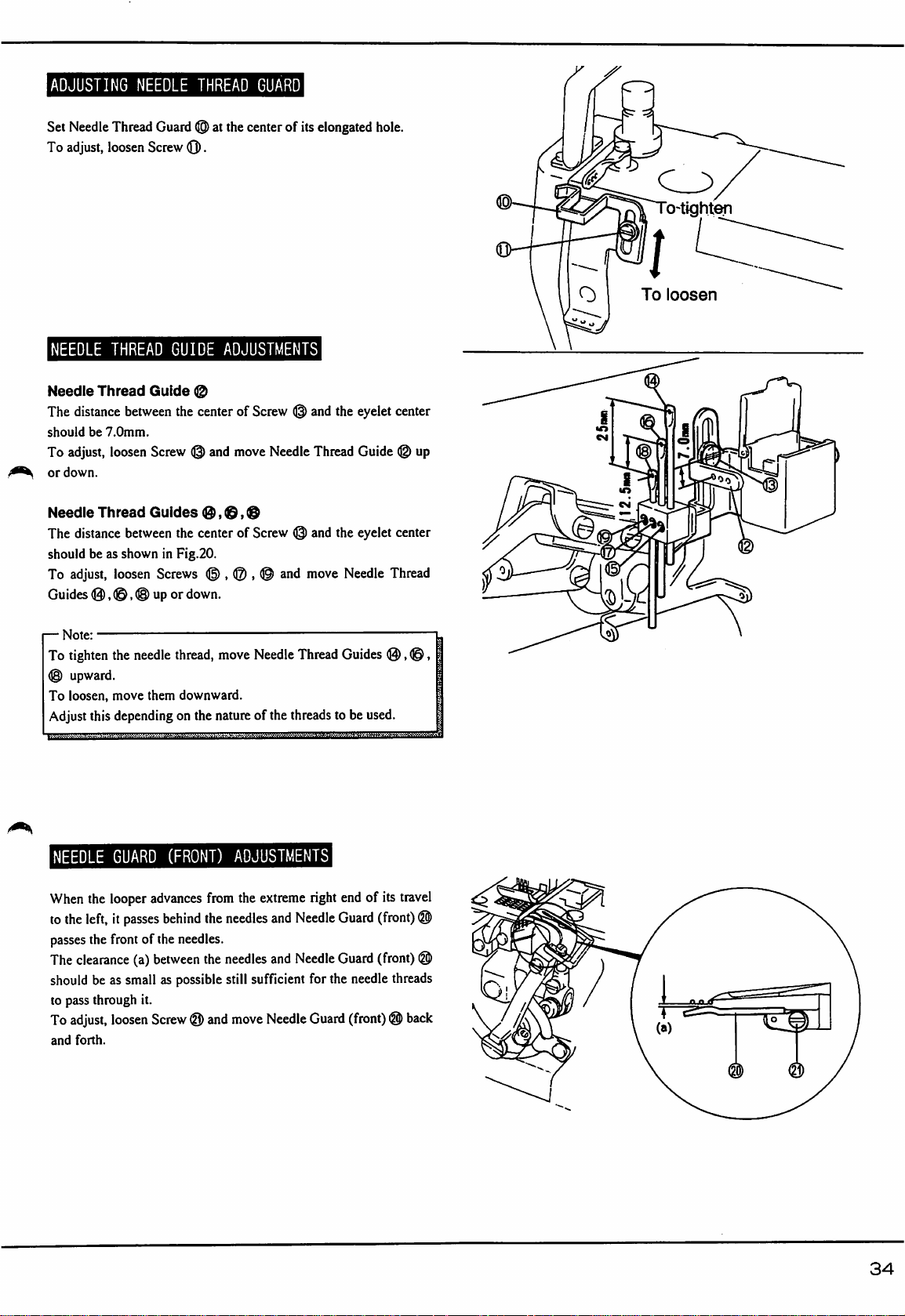
ADJUSTING
Set
Needle
To
adjust,
loosen
NEEDLE
Thread
Guard
Screw
THREAD
(@>
at
(Q).
the
center
GUARD
of
its
elongated
hole.
aM
c_^
o-tight^
To
loosen
NEEDLE
Needle
The
distance
should
be
To
adjust,
or
down.
Needle
The
distance
should
be
To
adjust,
Guides
(0,
—
Note;
To
tighten
©
upward.
To
loosen,
Adjust
this
THREAD
Thread
Guide
between
7.0mm.
loosen
Screw
Thread
between
as
shown
Guides
loosen
©, ® up
the
needle
move
them
depending
GUIDE
the
the
in
Fig.20.
ADJUSTMENTS
(g)
center
(g)
and
0,
@®
center
of
Screw ® and
move
Needle
of
Screw © and
Screws © , ® , © and
or
down.
thread,
move
Needle
Thread
downward.
on
the
nature
of
the
threads
the
Thread
the
move
Needle
Guides
to
be
eyelet
center
Guide
(g)
eyelet
center
Thread
®,
used.
up
©,
NEEDLE
When
to
the
passes
The
should
to
To
and
GUARD
the
looper
left,
it
passes
the
front
clearance
pass
adjust,
forth.
(a)
be
as
small
through
it.
loosen
(FRONT)
advances
of
the
between
from
behind
the
needles.
the
as
possible
Screw © and
ADJUSTMENTS
the
extreme
needles
and
Needle
needles
and
Needle
still
sufficient
move
for
Needle
right
end
Guard
Guard
the
needle
Guard
(front) © back
of
its
travel
(front)
@
(front)
threads
©
©
©
34
Page 37
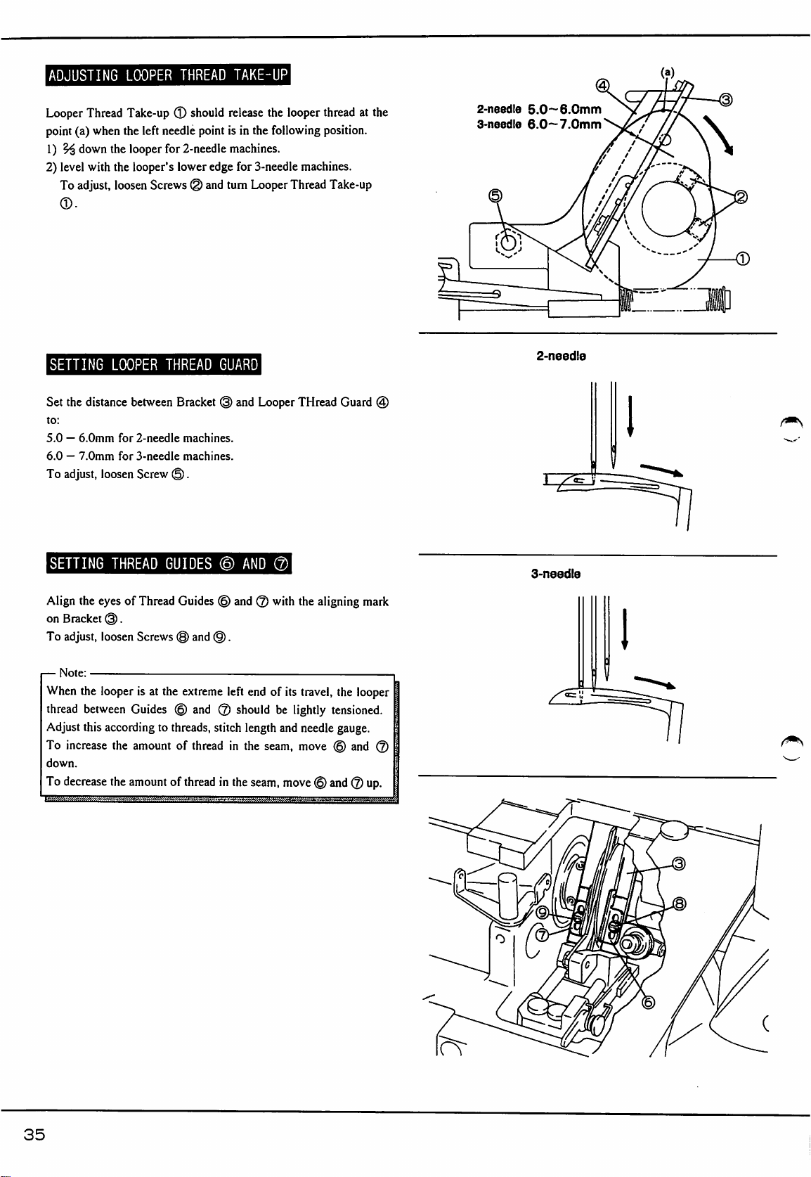
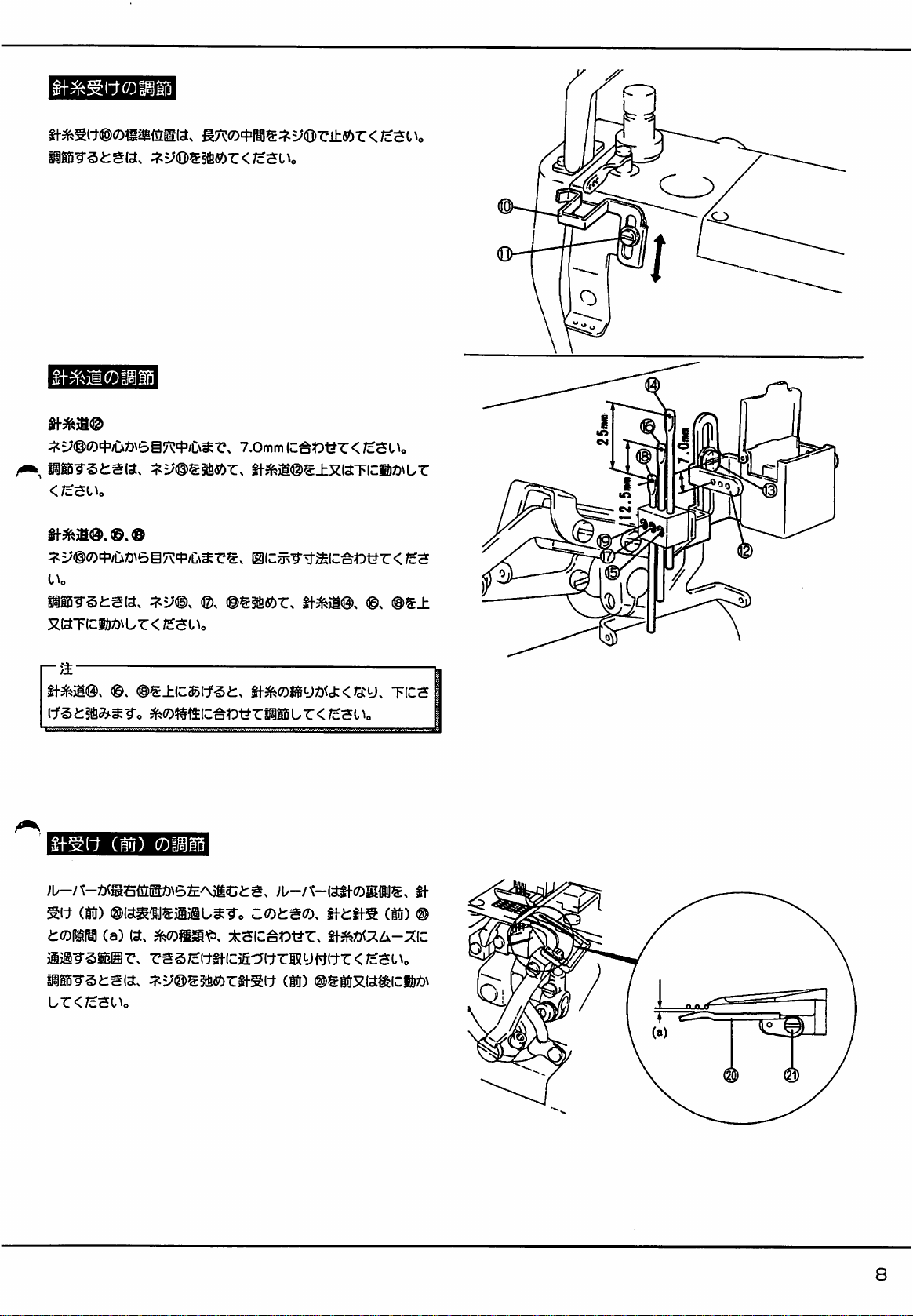
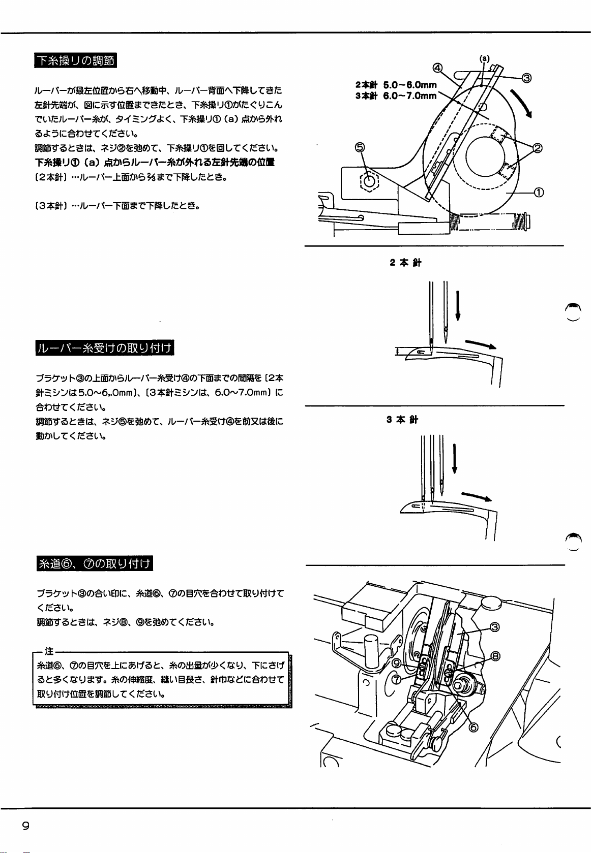
ADJUSTING
LOOPER
THREAD
TAKE-UP
Looper
Thread
point
(a)
when
1)
down
2)
level
with
To
adjust,
SETTING
Set
the
distance
to:
5.0 — 6.0mm
6.0 — 7.0mm
To
adjust,
Take-up ® should
the
left
needle
the
looper
for
the
looper's
loosen
LOOPER
between
for
for
loosen
lower
Screws © and
THREAD
Bracket @ and
2-needle
3-needle
Screw
@.
release
point
is
in
2-needle
machines.
edge
for
turn
GUARD
machines.
machines.
the
looper
the
following
3-needle
Looper
Looper
machines.
Thread
THread
thread
at
the
position.
Take-up
Guard
@
2-need!e
3-needle
5.0—6.0mm
6.0—7.0mm'
2-needl8
SETTING
Align
the
on
Bracket
To
adjust,
—
Note:
When
the
thread
between
Adjust
this
To
increase
down.
To
decrease
THREAD
eyes
(§).
loosen
looper
GUIDES © AND
of
Thread
Guides ® and
Screws ® and
is
at
the
extreme
@.
Guides ® and @ should
according
the
the
to
threads,
amount
amount
of
stitch
of
thread
thread
left
in
in
the
@
(2)
with
the
end
of
its
be
lightly
length
and
the
seam,
move
seam,
move © and @ up.
aligning
travel,
the
tensioned.
needle
gauge.
(§)
and
3-needle
mark
looper
(2)
35
Page 38
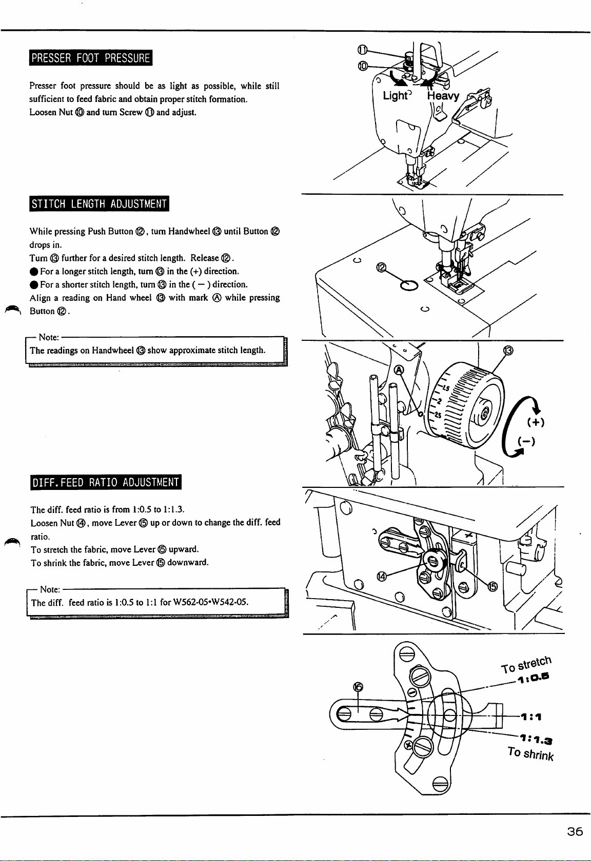
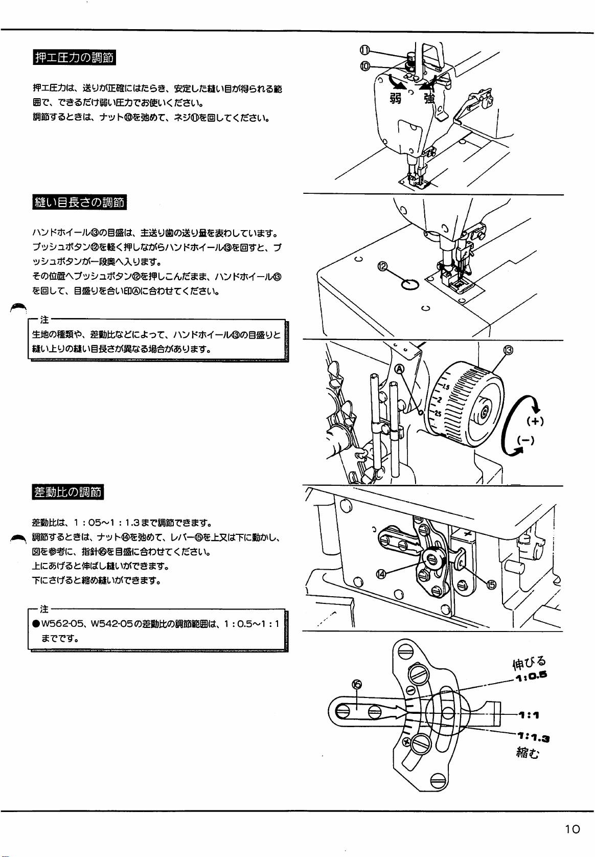
PRESSER
Presser
sufficient
Loosen
FOOT
foot
to
feed
Nut ® and
PRESSURE
pressure
should
fabric
and
turn
Screw
be
as
obtain
proper
(Q)
and
light
as
stitch
adjust.
possible,
formation.
while
still
STITCH
While
drops
Turn © further
0
#
Align a reading
Bunon
—
Note:
The
DIFF.FEED
LENGTH
pressing
in.
Push
for a desired
For a longer
For a shorter
stitch
stitch
on
©.
readings
on
Handwheel
RATIO
ADJUSTMENT
Button
©,
stitch
length,
turn © in
length,
turn © in
Hand
wheel © with
|)
show
i
ADJUSTMENT
turn
Handwheel © until
length.
Release
the
(+)
direction.
the
(— ) direction.
mark ® while
approximate
Button
©.
stitch
length.
©
pressing
The
diff.
Loosen
ratio.
To
stretch
To
shrink
—
Note:
The
diff.
feed
Nut
the
the
feed
ratio
is
®,
move
fabric,
fabric,
ratio
is
from
1:0.5
to
1:1.3.
Lever © up
move
move
1:0.5
or
Lever © upward.
Lever © downward.
to
1:1
for
down
to
change
the
W562-05*W542-05.
diff.
feed
o
iSJ
1
shrink
36
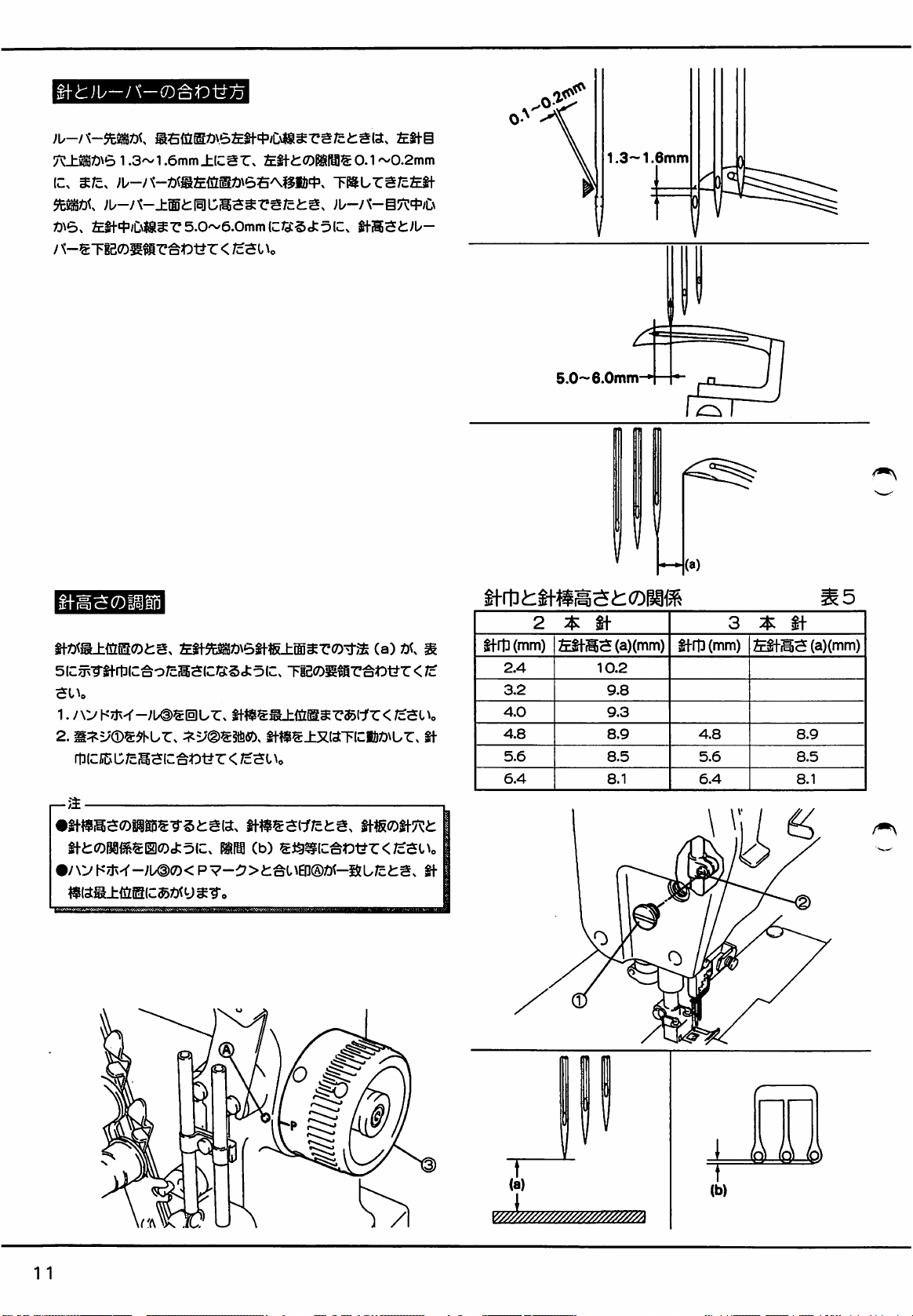
Page 39

ADJUSTING
When
the
looper
be
1.3 — i.bmm
clearance
When
of
the
Adjust
the
the
looper
left
to
left
needle
in
the
NEEDLE
point
is
above
the
left
needle
needle
comes
blade,
the
distance
centerline
following
manner.
AND
LOOPER
behind
the
the
top
should
down
between
should
be
left
needle
of
the
left
be
0.1 — 0.2mm.
and
its
point
the
5.0 — 6.0mm.
centerline,
needle
is
flush
looper
eye,
with
eye
it
and
center
should
the
the
top
and
1.3-1.6mm
5.0—6.0mm
NEEDLE
The
standard
The
needle
and
the
position.
1.
Raise
wheel
2.
To
adjust,
the
needle
—
Note:
>
After
the
center
(b)
is
I
When
handwheel
HEIGHT
settings
height
is
needle
plate
the
needle
bar
@.
remove
bar
up
or
this
adjustment,
of
the
needle
even.
the
needle
should
SETTING
are
shown
the
distance
surface
to
the
Cap
Screw
down
as
make
hole
bar
is
at
meet
mark
in
Table
(a)
between
when
the
highest
®,
loosen
required.
sure
that
each
in
the
needle
its
highest
(§)
5.
the
left
needle
is
at
position
by
Screw
(§),
needle
passes
plate
and
position,
mark P on
needle
point
the
highest
turning
and
hand
move
through
that
the
gap
the
NEEDLE
Needle 1 Left
gauge(mm) I height
2.4
3.2
4.0
4.8
5.6
6.4
HEIGHT
2-needle
i
needle
(a)(mm)
10.2
9.8
9.3
8.9
8.5
8.1
(a)
Needle
gauge(mm)
4.8
5.6
6.4
3-needle
Left
height
Table
needle
(a)(mm)
8.9
8.5
8.1
5
T"
(a)
37
I
T
(b)
(]>
/p\
Page 40
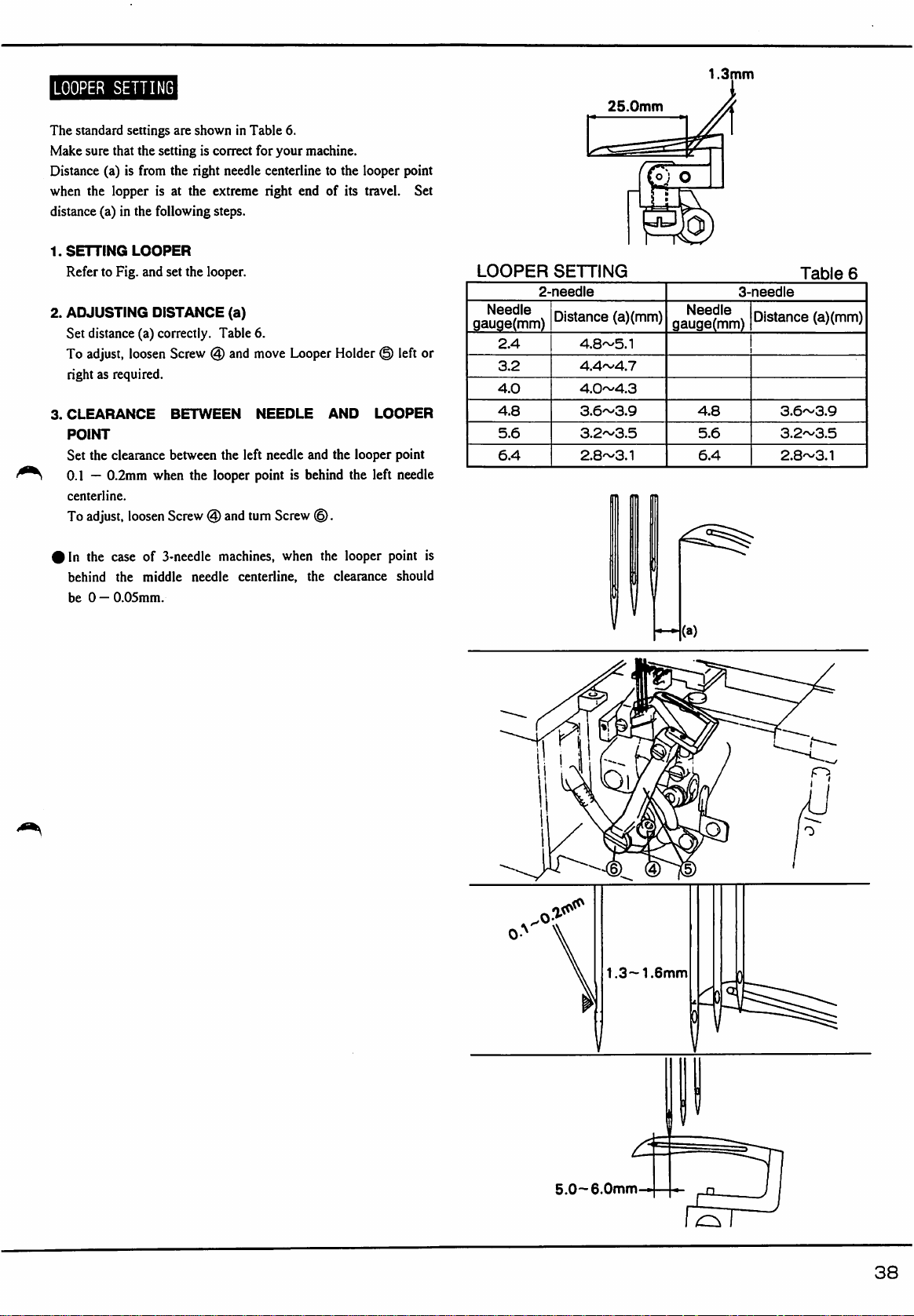
LOOPER
The
standard
Make
sure
Distance
when
distance
1.
2.
3.
(a)
the
(a)
SETTING
Refer
to
ADJUSTING
Set
distance
To
adjust,
right
as
CLEARANCE
POINT
Set
the
0.1 — 0.2mm
centerline.
To
adjust,
SETTING
settings
that
is
lopper
in
Fig.
are
the
setting
from
the
is
at
the
following
LOOPER
and
set
DISTANCE
(a)
correctly.
loosen
Screw @ and
required.
BETWEEN
clearance
between
when
loosen
Screw
shown
is
correct
right
the
extreme
the
looper.
the
looper
(§)
in
Table
needle
steps.
(a)
Table
the
left
and
turn
6.
for
your
machine.
centerline
right
end
6.
move
Looper
NEEDLE
needle
and
point
is
behind
Screw
®.
to
the
looper
of
its
Holder
AND
the
looper
the
point
travel.
(§)
left
LOOPER
Set
point
left
needle
or
LOOPER
Needle
gauge(mm)
2.4
3.2
4.0
4.8
5.6
6.4
SETTING
2-needle
Distance
4.8~5.1
4.4^4.7
4.0~4.3
3.6~3.9
3.2~3.5
2.8~3.1
25.0mm
(a)
(mm)
1.3mm
Needle
gauge(mm)
4.8
5.6
6.4
3-needle
Distance
3.6~3.9
3.2~3.5
2.8~3.1
Table
(a)(mm)
6
#ln
the
behind
be 0 —0.05mm.
case
the
of
3-needle
middle
machines,
needle
when
centerline,
the
the
looper
clearance
point
should
O
\
is
(a)
o
5.0—6.0mm
rsT
38
Page 41

ADJUSTING
Needle
Guard ® should
right
needle
point
is
behind
between
when
1.
2.
the
the
looper
Adjust
so
top
of
the
position.
To
adjust,
down.
To
obtain
and
move
NEEDLE
and
the
the
right
middle
point
that
the
right
loosen
the
above
Needle
GUARD
work
so
that
looper
point
is 0 —
needle
centerline.
needle
and
the
is
behind
the
line
(A)
of
Needle
needle
eye
when
Screw
(§)
and
clearances 0 —
Guard ® back
the
clearance
0.05mm
Also
looper
middle
needle
Guard ® is
the
needle
move
Needle
0.05mm,
and
forth.
when
that
the
point
is 0 —
centerline.
is
Guard ® up
loosen
between
the
looper
clearance
0.05mm
below
at
its
lowest
Screw
the
the
or
@
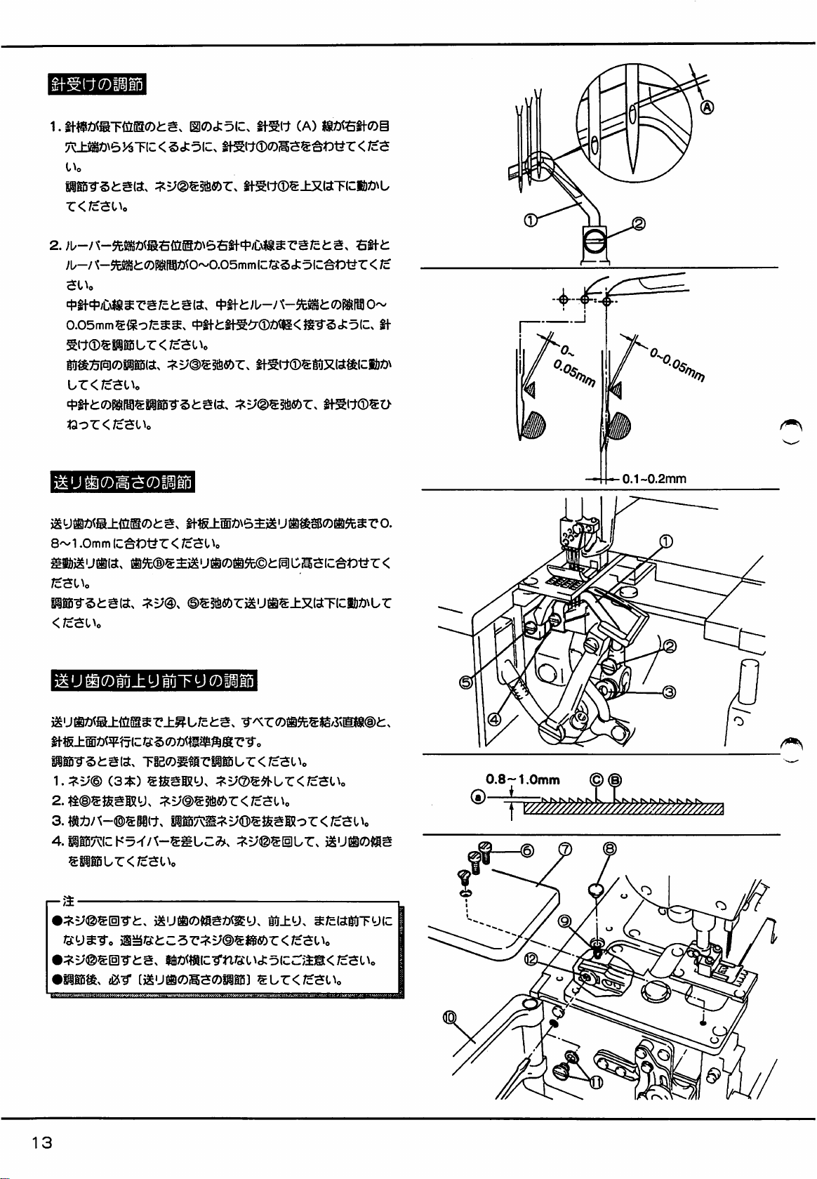
ADJUSTING
When
the
0.8 — 1.0mm.
Adjust
the
dog
point
To
adjust,
down
as
required.
ADJUSTING
When
the
angle
is
that
the
needle
To
adjust:
1.
Remove
2.
Remove
3.
Open
Side
4.
To
adjust
adjusting
—Note:
I
The
feed
tilt
by
turning
Set
Screw © to
I
Make
sure
turned.
I
Remember
adjustment.
FEED
main
feed
diff.
feed
C.
loosen
Screws @ and
FEED
feed
dogs
straight
plate
top
three
Screws ® and
Plug
(i)
Cover ® and
the
feed
hole
and
dog
tilt
Screw
the
that
the
to
adjust
DOG
HEIGHT
dog
is
at
dog
so
DOG
TILT
rise
to
line
(§)
across
surface.
and
loosen
remove
dog
turn
Screw
is
altered
(g).
correct
shaft
does
the
feed
its
hightest
that
©,
their
Cover
Screw
tilt,
position,
point B is
and
highest
all
move
the
tooth
(2).
even
the
position,
tips
®.
Screw
([]).
insert a screwdriver
®.
into
either
forward
position
and
tighten
not
slide
out
when
dog
height
after
set
the
height
with
main
feed
dogs
the
is
parallel
into
tilt
or
backward
Screw
@.
Screw © is
the
feed
to
feed
up
or
standard
with
the
dog
tilt
0.1~0.2mm
0.8-1.0mm
T
©
39
Page 42

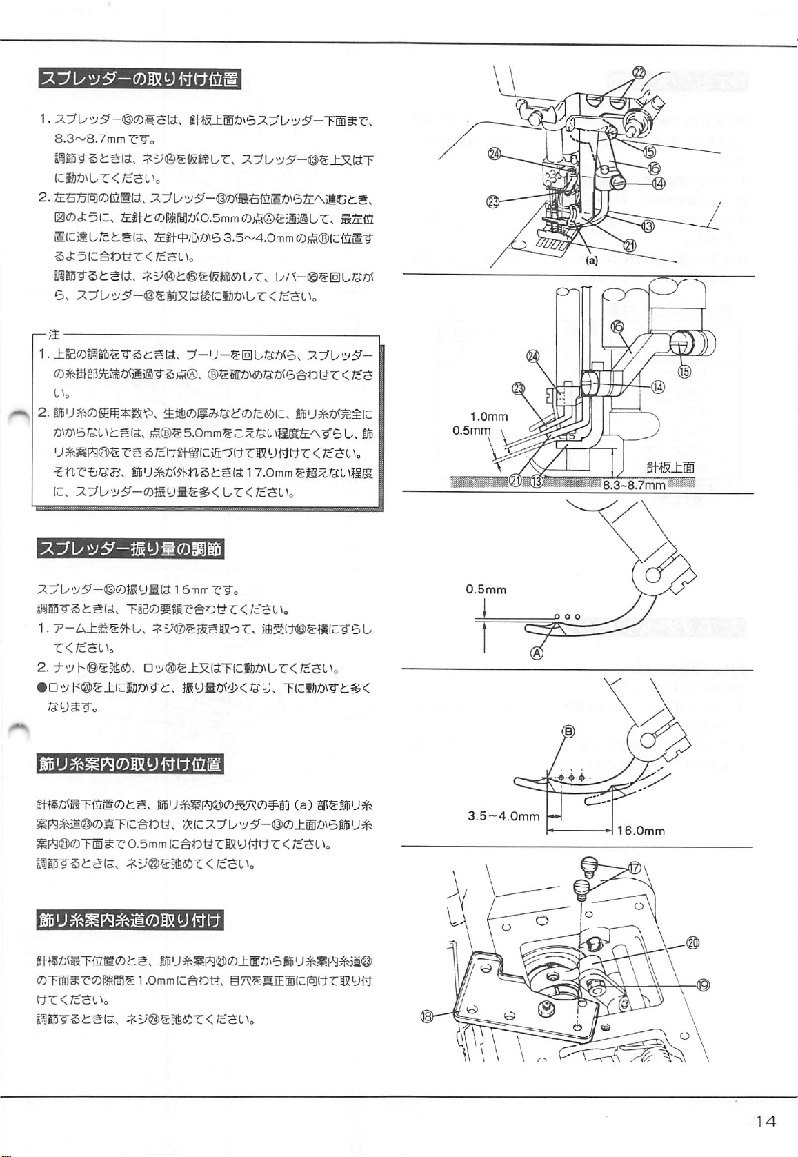
iSETTING
POSITION
OF
SPREADER
I
HEIGHT:
should
SIDEWISE
(A)
spreader
should
To
1.
The
be
8.3 — 8.7mm.
approximately
reaches
be
at
adjust:
Lightly
loosen
move
Spreader © back
position.
2.
Move
Spreader © up
9.7mm.
1.
When
making
check
points © ,
spreader
2.
If
the
spreader
number
the
point
Thread
Guide © as
If
the
spreader
adjustment,
not
exceeding
height
of
POSITION:
0.5mm
the
exreme
the
point
(B)
Screws @ and © .
Tighten
Tighten
Screw©.
Screw
the
above
(!)
passes.
thread
of
spreader
(g)
then
to
the
thread
increase
17.0mm.
threads
left
near
the
spreader
The
hooking
in
front
of
left
end
of
3.5 — 4.0mm
and
forth
or
down,
©.
adjustment,
where
the
is
hooked
or
the
not
exceeding
as
possible
is
not
hooked
the
following
from
the
needle
point
should
the
left
needle.
its
travel,
the
from
the
left
While
tuming
to
set
and
set
its
height
turn
the
thread
carrying
imperfectly
fabric
thickness,
5.0mm
and
to
the
needle
even
under
(the
plate
surface
pass
the
point
When
the
hooking
needle.
point
Lever © .
the
left-to-right
to
9.2
handwheel
notch
because
set
holder.
spreader
and
of
the
of
the
then
shift
Spreader
the
above
stroke)
—
1.0mm
0.5mm
Needle
top
plate
The
stroke
of
1.
Remove
2.
Loosen
0
To
To
Set
when
clearance
I
SETTING
When
between
1.0mm.
The
the
Nut © and
decrease
increse
part
(a)
the
needle
between
the
needle
Spreader
eye
of
Thread
Spreader©
arm
cover
move
the
stroke,
the
stroke,
move
of
Thread
Guide © just
bar
is
Thread
THREAD
GUIDEi
bar
is
Thread
Guide © should
is
16.0mm.
and
Screws
©,
Rod © up
move
Rod © up.
Rod © down.
below
at
its
lowest
Guide © and
at
the
lowest
Guide © and
face
and
shift
Cover
or
down
as
required.
the
eye
of
position.
Spreader © for
position,
Thread
Also,
set
the
Guide © for
forwards.
©.
Guide
©
set
the
0.5mm.
clearance
0.5mm
3.5—4.0mm
16.0mm
Page 43

ADJUSTING
The
standard
The
foot
lift
needle
plate
To
adjust:
1.
Turn
the
positions.
2.
Loosen
Nut
3.
Lower
Lever @ and
for
your
4.
In
the
above
Lever
@.
Lock
this
FOOT
settings
when
is
the
are
distance
the
presser
handwheel
(§)
and
tighten
machine.
condition,
position
with
LIFT
shown
and
raise
adjust
Nut
in
Table
(a)
between
foot
is
raised.
lower
the
Screw
0.
Presser
Screw
(§).
7.
the
feed
Foot
(5)
(2)
presser
dogs
to
correct
so
that
foot
to
their
its
head
and
the
lowest
ghight
(a)
touches
FOOT
Machine
W562-01
W562 - 02
W562 - 03
W562 - 05
W562 - 06
W562 - 07
Note:
The
number
ADJUSTING
To
adjust
left-to-right
movement
1.
2.
of
Remove
the
Guard © aside.
Loosen
two
mark
©.
Tighten
LIFT
type
of
needle
SPREADER
the
needle
arm
cover.
Screws
Screw
2-neeclle
varies
TIMING
timing
of
bar:
Remove
@.
Align
(2).
Foot
111
6.3
6.3
6.3
5.3
5.3
5.3
foot
lift.
the
Spreader
Screws
mark © of
Table
Ft
(mm)
3-needle
to
(§)
the
5.0
5.0
5.0
5.0
5.0
5.0
the
up
and
upper
7
and
down
move
Oil
shaft
with
41
Page 44

ADJUSTING
TO
THE
NEEDLE
In
coordinating
down
movement
the
top
of
the
left
side
of
the
left
to
the
left
(on
moves
to
the
right
illustration.
To
adjust:
1.
Remove
2.
Loosen 4 Screws
of
9
To
position
9
To
in
—
Note:
The
needle
Adjusting
change
In
this
the
Upper
Belt
advance
in
the
retard
the
the
(— ) direction.
looper
holder
bar
is
at
left-to-right
when
the
case,
adjust
LEFT-TO-RIGHT
left-to-right
of
the
needle
needle
the
back
(on
arm
cover.
®,
Gear
the
looper
(-•-)
direction.
looper
is
at
its
lowest
looper
as
timing
needle
eye
and
is
Just
the
side
of
the
front
turn
Handwheel ® and
(g).
timing
timing
against
the
extreme
position.
timing
avoiding
in
the
above.
bar,
same
the
side
of
TIMING
of
the
be
sure
the
point
both
needles)
of
the
against
the
right
the
looper
motion
OF
looper
the
distance
of
the
looper
when
the
and
when
needles).
shift
the
needle,
needle,
shift
end
of
its
to
the
is
adjusted.
THE
LOOPER
to
the
between
at
the
looper
the
See
the
the
position
shift
the
position
travel
when
needle
up
and
right
moves
looper
right
the
the
may
1
ADJUSTING
LOOPER'S
To
adjust
Eccentric ® with
ADJUSTING
The
looper
moves
when
the
motion
procedure.
1.
Loosen
To
increase
©
counter-clockwise.
—
Note:
t
After
the
needle
I
Please
necessary
size
THE
BACK
this
timing,
the
LOOPER
passes
the
to
the
left
and
looper
moves
correctly
the
needle
Nut
(Q)
the
above
bar
note
to
be
is
for
and
looper
adjustment,
and
that
adjusted
fitted.
TIMING
AND
FORTH
loosen
Screw ® and
mark
(§)
on
AVOIDING
back
side
the
looper
to
the
the
needle
turn
Adjusting
avoiding
To
decrease
looper.
the
If
looper
unless
BETWEEN
MOVEMENT
the
crankshaft.
MOTION
of
the
needles
passes
the
right.
Adjust
size
by
referring
Screw
motion,
it,
turn © clockwise.
check
the
synchronization
it
is
not
correct,
avoiding
otherwise
NEEDLE
align
the
when
front
of
the
looper
to
©.
turn
re-adJust.
motion
an
extremely
AND
mark © on
the
looper
the
needles
avoiding
the
following
between
may
not
different
be
42
Page 45

UNDER
The
The
The
the
LUBRICATION
Before
idle
FABRIC
fabric
trimmer
knife
movement
knives
trim
lace
fed
out
the
machine
for a period
TRIMMER
of
the
is
synchronized
the
excess
by
the
elastic
is
operated
of
time,
oil
(FT140)
W500
is a continuous
fabric
while
feeder
can
for
the
Crank
®.
with
sewing,
be
first
type.
the
feed
closed
time
or
dog
motion.
so
the
body
neatly.
after
it
has
and
been
ADJUSTING
Fabric
Guide
edge
and
the
To
adjust,
loosen
as
required.
ADJUSTING
The
presser
Adjust
this
thick
elastic,
elastic
can
be
To
adjust,
loosen
FABRIC
(g)
right
Screw
GUIDE
ensures a constant
needle.
(3)
PRESSER
foot
on
the
W500-05
according
tilt
then
to
the
front
fed
smoothly
the
Nut © and
and
move
FOOT
elastic
edge
of
under
turn
distance
Fabric
TILT
can
be
and
the
presser
the
Screw
between
Guide
tilted.
fabric
foot
presser
©.
the
(g)
right
to
be
sewn.
upwards.
foot.
fabric
or
left
For
The
43
Page 46

REPLACING
1.
Turn
the
position.
—
Note:
Set
Upper
Knife
Upper
Knife
2.
Turn
the
position.
approximately
3.
Insert a piece
the
knives
UPPER
handwheel
Replace
Holder
handwheel
Make
cut
with a new
(2)
with
©.
sure
0.5mm.
of
threas
sharp.
KNIFE
and
Screw
and
bring
Upper
upper
bring
Upper
that
the
between
the
Knife @ to
knife.
so
that
its
Knife @ to
overlap
knives
edge
of
and
its
(a)
the
knives
make
highest
is
flat
its
lowest
sure
on
is
that
O.Srnm
n
REPLACING
1.
open
the
Knife
(Q)
2.
Shift
Upper
Insert
Lower
that
the
plate
surface.
3.
Insert a piece
the
knives
POSITION
The
position
position
Adjust
sewn
To
To
©
of
the
this
together
adjust,
loosen
move
Holder©
to
the
right,
LOWER
side
•
Knife
cutting
cut
OF
of
knives.
so
that
with
KNIFE
cover.
Holder®
Knife
(Q)
edge
of
of
thread
sharp.
LOWER
Lower
Knife
the
excess
the
elastic/lace
Screws
(g),
to
the
Loosen
into
Screw © and
to
the
Lower
Lower
Knife
between
KNIFE
the
HOLDER
right.
Knife
knives
Holder @ determines
fabric
is
trimmed
neatly.
(©
and
turn
Adjusting
left,
turn
Screw ® clockwise.
turn © counter-clockwise.
Holder ® .
is
level
and
and
remove
with
the
make
sure
the
trimming
the
fabric
Screw
©.
To
Lower
Be
sure
needle
that
move
is
—
Note:
Re-adjust
the
ADJUSTING
Set
knives
lowest
To
down
the
position
above
adjustment
the
height
of
is
approximately
position.
adjust,
loosen
as
required
of
Knife
is
made.
THE
HEIGHT
Upper
Knife
0.5mm
Screw © and
when
the
upper
Guide © on
OF
UPPER
Holder ® so
when
the
move
Upper
knife
is
at
the
presser
KNIFE
that
the
upper
Knife
the
lowest
foot
when
HOLDER
overlap
of
the
knife
is
at
Holder ® up
position.
its
or
44
Page 47

METERING
The
metering
accurately.
The
feeding
range
DEVICE
device
feeds
is
0.9 — 3.5mm
(MD230)
elastic
or
lace
per
stitch.
(width
up
to
40mm)
SETTING
Refer
sequence).
LUBRICATION
The
with
LUBRICATION
Align
(A)
on
Remove
Remove
or
not.
LUBRICATION
LACE
to
Fig.
Remove
clutches
and
grease.
mark
(A)
Plate
(§).
Cap
Screw
Always
Screw
GUIDE
Screw ® and fit
bearings
keep
TO
CLUTCH
on
Crank ® and
(§)
and
(®
and
check
TO
BEARINGS
of
the
metering
them
full
insert
whether
with
mark
(A)
the
grease.
the
Lace
Guide @ ((§) ~ (§)
device
come
grease.
on
Sleeve
Q)
clutch
is
full
in
pre — filled
with
mark
with
grease
m
To
lubricate
The
amount
SETTING
Set
Lace
Guide
not
touching
To
adjust,
the
bearings,
of
grease
LACE
GUIDE
(Lower) © as
the
spreader.
loosen
Screw ® and
remove
can
be
Cap
chacked
through
(LOWER)
close
as
turn
Stopper
Screw
(Q)
hole
possible
©.
and
B.
to
insert
grease.
the
needle
but
45
Page 48

SETTING
Install
the
|T1
Guide
Set
Guide
correct
To
adjust,
required.
POSITIONS
elastic
guides
on
the
presser
<I|)
so
position.
loosen
OF
ELASTIC
properly
according
foot
that
elastic
is
Screw © and
fed
under
move
GUIDES
to
the
width
of
the
presser
foot
Guide © left
or
elastic.
in
the
right
as
Guides ® and
Set
Guides @ and © in
To
adjust,
©
left
or
[3]
Guides © and
Set
guides © and © so
in a straight
To
adjust,
@
left
or
ADJUSTING
Two
settings
pn
Standard
On
the
standard
stitch.
To
adjust,
the
(+)
direction.
To
decrease
direction.
®
loosen
Screws © and
right
as
required.
©
line.
loosen
Screws © and
right
as
required.
ELASTIC
are
available
setting
setting,
loosen
Wing
the
feeding
line
with
that
elastic
FEEDING
for
this
metering
the
feeding
Nut @ and
rate,
turn
Guide
©.
©,
and
move
runs
into
Guides © and
©,
and
move
RATE
device.
range
is
0.9 — 2.2mm
turn
Adjusting
Screw ® in
Guides © and
Guides © and
Screw @ in
the
(—
)
©
per
©
r~
Note:
If
the
proper
feeding
adjustment, "pressure
referring
to
page
amount
21.
cannot
be
adjustment"
should
obtained
be
after
also
the
above
made
by
46
Page 49
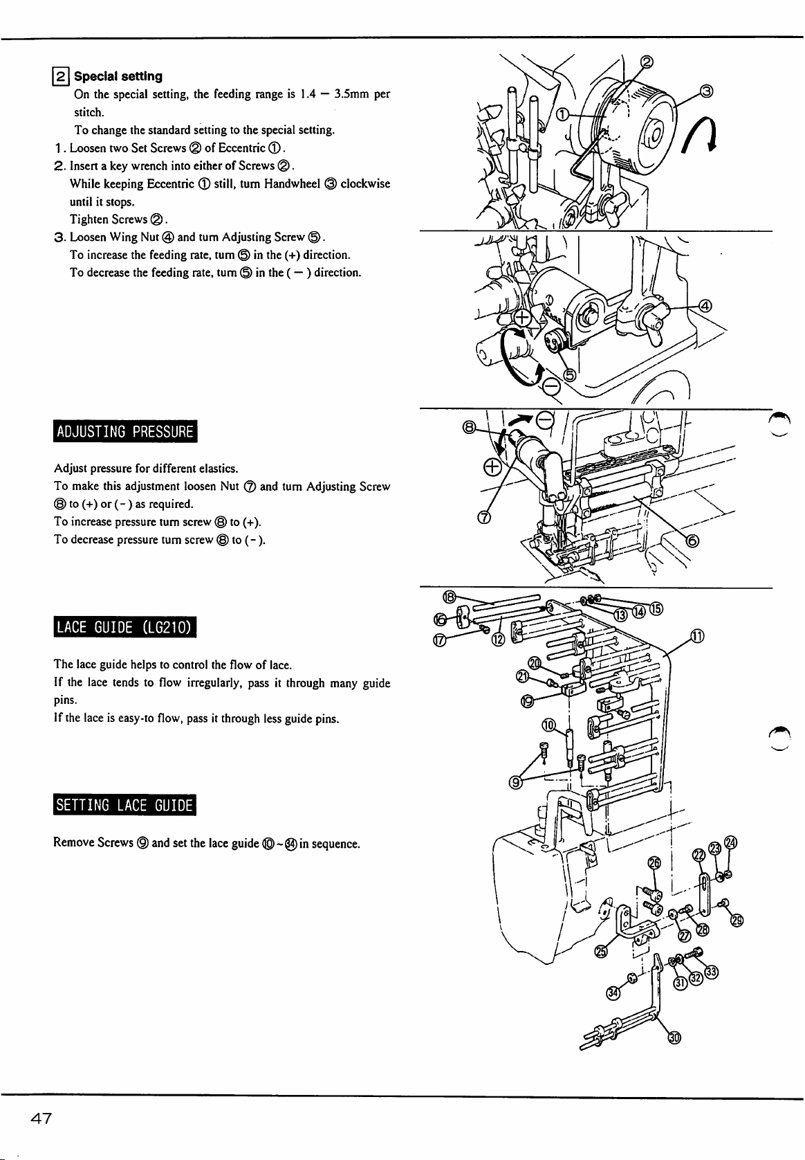
Special
On
the
stitch.
To
change
1.
Loosen
2.
Insert a key
While
until
Tighten
3.
Loosen
To
increase
To
decrease
setting
special
the
two
Set
wrench
keeping
it
stops.
Screws
Wing
the
the
setting,
the
feeding
standard
Screws @ of
Eccentric ® still,
®.
Nut @ and
feeding
feeding
setting
into
either
turn
rate,
rate,
to
the
Eccentric
of
Screws
turn
Adjusting
turn © in
turn © in
range
is
1.4 — 3.5nim
special
setting.
®.
per
(§).
Handwheel @ clockwise
Screw
(g).
the
(+)
direction.
the
(— ) direction.
r\
ADJUSTING
Adjust
pressure
To
make
this
©
to
(+)
or ( -)
To
increase
To
decrease
LACE
GUIDE
The
lace
guide
If
the
lace
pins.
If
the
lace
is
SETTING
PRESSURE
for
different
adjustment
as
required.
pressure
turn
pressure
turn
(LG210)
helps
to
control
tends
to
flow
easy-to
flow,
LACE
GUIDE
elastics.
loosen
Nut © and
screw © to
screw © to
irregularly,
pass
(+).
(-).
the
flow
pass
it
through
of
lace.
less
turn
Adjusting
it
through
guide
many
pins.
Screw
guide
Remove
47
Screws © and
set
the
lace
guide
in
sequence.
Page 50

SETTING
Refer
to
1.
Attach
2.
Attach
3.
Insert
height
TAPE
BINDER
Fig.
and
set
Tape
Bracket @ to
Bracket ® to
Binder ® into
with
Screw®.
Binder ® for
the
front
Binder ® with
Bracket
cover
with
Screws
®.
Set
W562-02
(W542-02).
Screws®.
®.
Binder ® to
the
0
0?^
correct
©
CHANGING
•
W562-01»
•
W542-01.
On
these
subclasses,
from
1:0.5~1:1.3
Refer
to
Fig.
Lever®.
i
—
Note:
Correct
feeding
feed
dog
adjustment
THE
02.
02.
(standard)
Loosen
amount
does
not
is
made.
MAXIMUM
03,
03.
normal
FEED
06.
06.
diflerential
to
1:0.5~1:1.8.
Screw ® and
(stitch
lengh)
touch
the
RATIO
07
07
widen
should
needle
feed
plate
ratio
can
the
moving
be
used
when
be
changed
range
so
that
the
of
the
above
48
Page 51
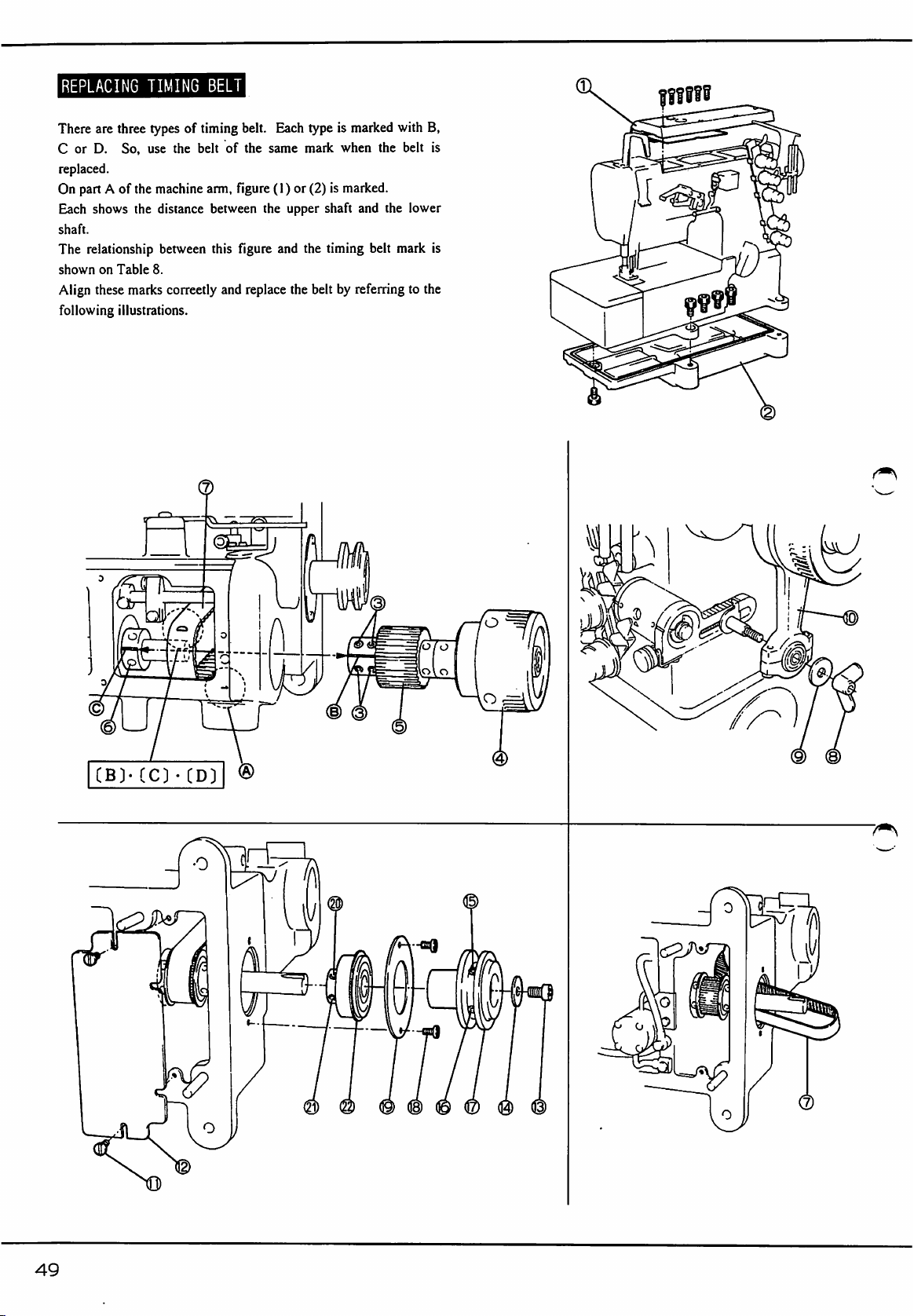
REPLACING
There
are
three
C
or
D.
So,
replaced.
On
part A of
Each
shows
shaft.
The
relationship
shown
on
Table
Align
these
marks
following
illustrations.
TIMING
types
use
the
the
machine
the
distance
between
8.
correetly
BELT
of
timing
belt
arm.
between
this
belt.
of
the
figure
figure
and
replace
Each
same
(1)
the
and
type
mark
or
(2)
upper
shaft
the
the
belt
is
marked
when
is
marked.
and
timing
belt
by
referring
with
the
the
mark
B,
belt
is
lower
is
to
the
0
7^
49
Page 52
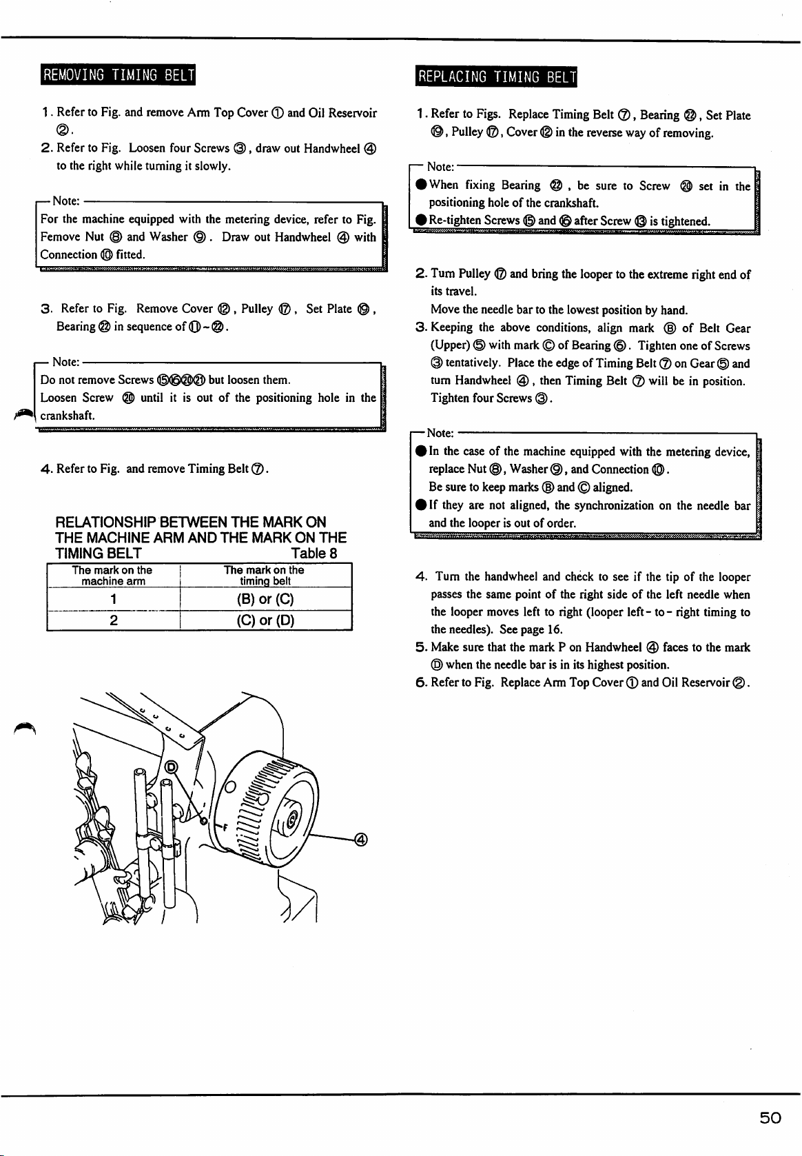
REMOVING
1.
Refer
to
2.
Refer
to
to
the
right
—
Note:
For
the
machine
Femove
Connection
3-
Nut
Refer
to
(©
Bearing ® in
—
Note:
Do
not
remove
Loosen
crankshaft.
4.
Screw
Refer
to
RELATIONSHIP
THE
MACHINE
TIMING
The
mark
machine
TIMING
Fig.
and
Fig.
Loosen
while
equipped
(§)
and
fitted.
Fig.
sequence
Screws
@)
Fig.
and
BELT
on
arm
1
2
BELT
remove
four
turning
Washer
Remove
of
(©©QPQj)
until
it
remove
BETWEEN
ARM
the
Arm
Top
Screws
it
slowly.
with
the
metering
(§).
Draw
Cover ® .
0) - (§).
but
loosen
is
out
of
Timing
Belt
AND
THE
The
Cover ® and
(3),
draw
out
device,
out
Handwheel @ with
Pulley
®,
them.
the
positioning
Q).
THE
MARK
MARK
mark
timing
(B)
(0)
on
the
belt
or(C)
or(D)
ON
Table
Oil
Reservoir
Handwheel
refer
Set
hole
ON
THE
to
Plate
in
8
@
Fig.
the
REPLACING
1.
Refer
to
Figs.
®,
Pulley
—
Note:
IWhen
2.
3.
fixing
positioning
1
Re-tighten
Turn
Pulley © and
its
travel.
Move
the
needle
Keeping
the
(Upper) © with
@
tentatively.
turn
Handwheel @ ,
Tighten
—
Note:
I
In
replace
Be
)
If
and
4.
the
the
5.
Make
®
6.
Refer
four
the
case
Nut
sure
to
they
are
the
looper
Tum
the
passes
the
looper
needles).
sure
when
the
to
Fig.
keep
TIMING
®,
Bearing @ ,
hole
Screws © and ® after
above
Screws
of
the
©,
not
is
handwheel
same
moves
See
that
needle
Replace
BELT
Replace
Cover ® in
of
the
crankshaft.
bring
bar
to
the
Timing
the
the
lowest
conditions,
mark © of
Place
the
edge
then
Timing
©.
machine
Washer
marks
aligned,
out
point
left
page
the
equipped
@,
(§)
and © aligned.
the
of
order.
and
check
of
the
to
right
16.
mailc P on
bar
is
in
Arm
Top
Belt
reverse
be
sure
Screw ® is
looper
to
position
align
Bearing
and
©.
of
Timing
Belt @ will
Connection
synchronization
to
see
right
side
(looper
Handwheel © faces
its
highest
Cover
©,
Bearing
way
to
Screw @ set
®,
of
removing.
tightened.
the
extreme
by
mark
Tighten
Belt ® on
with
the
if
the
of
the
left - to - right
position.
(3)
and
right
hand.
(§)
of
one
Gear © and
be
in
metering
®.
on
the
tip
of
left
needle
to
Oil
Reservoir
Set
Plate
in
the
end
of
Belt
Gear
of
Screws
position.
device,
needle
bar
the
looper
when
timing
to
the
mailc
©.
50
Page 53

The
stitch
machine.
timing
gauge
formation
In
order
set
(Pan
is
to
No.510-91)
affected
adjust
the
very
much
timings
is
available
by
the
easily
and
as
an
timings
of
correctly,
option.
Talbe
the
the
9
Machine
Left
needle
Looper
Spreader
Spreader
Spreader
(gauge)
height A (mm)
setting B (mm)
height C (mm)
height O (mm)
stroke E (mm)
W562-21(356}
9.3
3.7-4.0
9.7-10.2
18-18.5
W562 - 21(364)
9.7-10.2
5.5-6
18-18.5
Feed
dog
Presser
Maximum
hieght F (mm)
foot
lift G (mm)
speed
(S.P.M)
1.2-1.5
1.2-1.5
Page 54
INTRODUCTION
This
booklet
maintenance
should
the
best
help
you
use
from
of
contains
the
to
it.
some
W500,
become
familiar
notes
which
should
with
on
be
the
machine
the
operation
useful
and
to
you
to
derive
and
and
liiiiKuaau
(1)
Make
sure
Belt
(2)
Take
care
when
well
as
when
(3)
Turn
off
Motor
(4)
Turn
off
Motor
(5)
Make
sure
Motor
inspect
the
machine.
(6)
Be
sure
to
completely
needles.
stopped
Cover
you
you
check
Switch
Switch
turn
off
is
properly
connect
Power
the
machine
whenever
in
the
event
has
completely
the
power
when
you
fitted.
Cord
before
you
leave
of
power
stopped
and
thread
the
to
Machine
switching
the
work
failure.
when
you
make
sure
machine
or
Motor
as
on.
table.
clean
or
Motor
has
replace
the
DAILY
Before
(1)
Check
(2)
Check
Check
(4)
Check
Foot.
(5)
Check
is
maintained
lubricated
After
close
(1)
Remove
(2)
If
any
mechanic
(3)
Be
sure
MAINTENANCE
morning
each
all
threading
the
start
Needle
Needles
about
30mm
oil
jets
at
enough.
of
work
dust
and
trouble
for
adjustment
to
place
is
the
lint
or
Dust
is
not
damaged
are
correctly
correct.
of
thread
in
Oil
Sight
specified
deposits
disorder
or
repair.
Cover
over
or
set.
chain
Window
level
and
on
the
is
found,
the
bent.
remains
are
normal.
the
hand-oiled
machine.
report
machine.
behind
Check
it
to
the
Presser
oil
parts
are
plant
PRECAUTIONS
(1)
Do
not
run
weeks.
(2)
Before
starting
idle
for
more
moving
pans.
(3)
Always
Gauge.
(4)
Change
(5)
Thread
keep
the
correctly
the
machine
machine
than a couple
oil
level
oil
at
the
end
as
shown
at
more
than
for
the
first
of
weeks,
between
of
the
the
first 4 weeks.
in
Treading
4,500
time,
or
munually
two
lines
Diagram
s.p.m.
for
if
the
machine
lubricate
on
Oil
on
Page
first
4
is
the
Sight
7.
52
Page 55

t553
;^ra^SSEl}Stl5-7-2
TEL
(06)
454-0561
PEGASUS
5-7-2.
Sagisu,
SEWING
Fukushima-ku,
MACHINE
Osaka
553,
Japan.
MFG.CO.,LTD.
Phone:
(06)
454-0561
Cat.
NO.9A2029
©1992
PEGASUS
January,
SEWING
1993
MACHINE
MFG.
CO..
LTD.
^
 Loading...