

Page 1

Thank you for purchasing Pegasus' labor saving device.
Study this manual very carefully before beginning any of
the procedures and then use the device correctly and
safely.
Keep this manual in a convenient place for quick refer-
ence when needed.
Thread trimmer
Models: W(T)500 Series
W700 Series
INSTRUCTIONS
UT
Device
Page 2

CONTENTS
CONTENTS
Installing and adjusting UT device
Threading diagram for W500/UT・
Taking the thread take-up bracket in and out
. . . . . . . . .
13
Threading diagram for W700/UT・
Taking the thread take-up bracket in and out
. . . . . . . . .
14
Sewing
. . . . . . . . . . . . . . . . . . . . . . . . . . . . . . . . . . . . . . . . . . . . . . . . . . . . . . . . . .
15
Adjusting the upper knife and flat spring
. . . . . . . . . . . . . . .
16
Adjusting the looper thread clamping spring
. . . . . . . . . .
16
Adjusting the lower knife
. . . . . . . . . . . . . . . . . . . . . . . . . . . . . . . . . . .
17
Checking for cutting action
. . . . . . . . . . . . . . . . . . . . . . . . . . . . . . . .
18
Adjusting the electric needle thread wiper
. . . . . . . . . . . . .
18
Adjusting the pneumatic needle thread wiper (air wiper)
. . . .
19
Adjusting the pneumatic top cover thread trimmer
. .
20
Adjusting the thread releaserr
. . . . . . . . . . . . . . . . . . . . . . . . . . . .
21
Adjusting the operation detector
. . . . . . . . . . . . . . . . . . . . . . . . .
21
1.Introduction
. . . . . . . . . . . . . . . . . . . . . . . . . . . . . . . . . . . . . . . . . . . . . . .
1
2.I
ndications of dangers, warnings & cautions
.
1-2
3.Safety precautions
. . . . . . . . . . . . . . . . . . . . . . . . . . . . . . . . . .
2-3
4.Notes for each procedure
. . . . . . . . . . . . . . . . . . . . . . . .
3-4
Applications and functions of the UT device
. . . . . . . .
5
Installation
Installing the electric presser foot lift
. . . . . . . . . . . . . . . . . . . . .
6
Installing the pneumatic presser foot lift
. . . . . . . . . . . . . . . . .
6
Installing the filter regulator and solenoid valve
. . . . . . .
7
Connecting air lines for the pneumatic UT
Connecting air lines for the pneumatic UT・
Adjusting the speed controller
. . . . . . . . . . . . . . . . . . . . . . . . . . . . . .
8
Connecting air lines for the pneumatic UT
(Pneumatic needle thread wiper)・
Adjusting the speed controller
. . . . . . . . . . . . . . . . . . . . . . . . . . . . . .
9
Connecting air lines for the pneumatic UT
(Pneumatic top cover thread wiper)
(W562-82 for angled stitching does not use this air piping.)・
Adjusting the speed controller
. . . . . . . . . . . . . . . . . . . . . . . . . . . .
10
Connecting air lines of the pneumatic UT for W562-82
for angled stitching・
Adjusting the speed controller
. . . . . . . . . . . . . . . . . . . . . . . . . . . .
11
Adjusting the air pressur
. . . . . . . . . . . . . . . . . . . . . . . . . . . . . . . . . . .
12
Page 3

Indicates an immediate hazard to life or limb.
Indicates a potential hazard to life or limb.
Indicates a possible mistake that could result in injury or damage.
DANGER
WARNING
CAUTION
1.Introduction@@@@@@@@@@@@@@
●This manual describes the instructions for using this device safely.
●Study this manual very carefully and understand fully how to operate, check, adjust and maintain the labor
saving device before beginning any of the procedures.
●You always perform operations close to moving parts such as needles when using industrial sewing machines.
Therefore you have to keep in mind you could easily touch them. To prevent accidents, it is essential that you
use the safe products supplied by Pegasus correctly.
All the people who will use sewing machines must study this manual and the instruction manual for sewing
machines very carefully and then take necessary safety measures before beginning any of the procedures.
2.
Indications of dangers, warnings and cautions
@
To prevent accidents, indications (symbols and/or signs) which show the degree of danger are used on our
products and in this manual. Study the contents very carefully and follow the instructions.
Indication labels should be found easily.
Attach new labels when they are stained or removed.
Contact our sales office when new labels are needed.
Besuretostudyverycarefully
for
for
safety.
safety.
Symbols,signsand/orsignalwordswhich
Symbols,signsand/orsignalwordswhich
attractusers'attention
attractusers'attention
1
Page 4
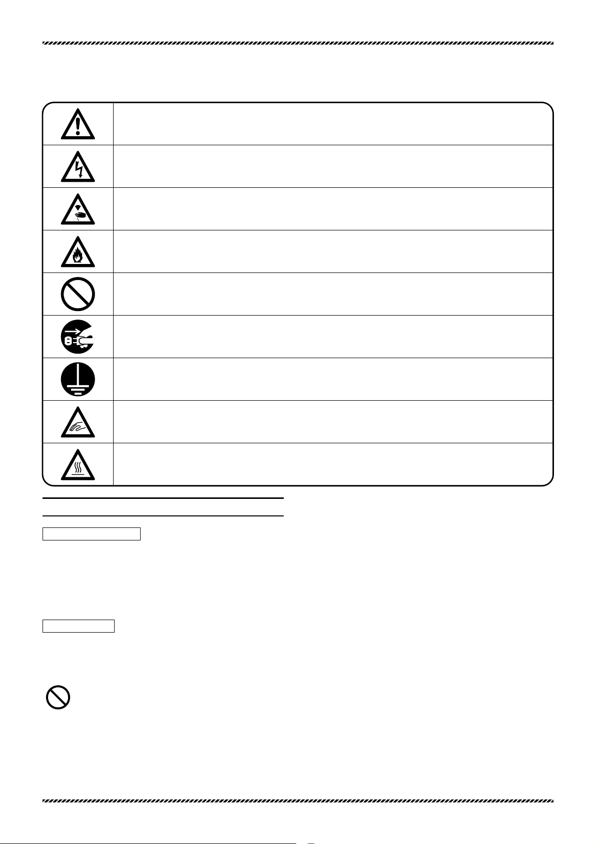
Be sure to follow the instructions when you operate the machine and/or labor saving device.
If you use the machine and/or labor saving device incorrectly, you may get an electrical shock.
If you use the machine and/or labor saving
device incorrectly, your hands and/or fingers may
be injured.
If you use the machine and/or labor saving device incorrectly, you may cause fire.
Never do this.
Unplug the machine or shut off the power when checking, adjusting and/or repairing the
machine and/or labor saving device, or when lightning may strike.
Be sure to connect to ground.
If you use the machine and/or labor saving device incorrectly, your fingers and/or hands
may be caught in them or it, causing trouble.
If you use the machine and/or labor saving device incorrectly, you may burn yourself.
3.Safety precautions
①Applications, purpose
The labor saving device is designed to increase quality and
productivity according to you needs.
Therefore never use the device for the applications which may
defeat the above purpose.
②Circumstances
Some circumstances when you are using the labor saving device
may affect its life, function, performance, and safety.
For safety, do not use the labor saving device under the
circumstances below.
1.Do not use the device near objects which make noise such as a
high-frequency welder, etc.
2.Do not use or store the device in the air which has vapor from
chemicals, or do not expose the device to chemicals.
Symbolsandmessages
Symbolsandmessages
3.Do not leave the device outside, in high temperatures or the
direct sun.
4.Do not use the device in high humidity or ambient temperatures
which may affect them.
5.Do not use the device on the condition that the voltage fluctua-
tion range is more than ± 10% of the rated voltage.
6.Do not use the device at the place where the supply voltage
specified for the control motor cannot be properly obtained.
7.Do not use the device at the place where the air supply specified
for the device cannot be properly obtained.
8.Do not expose the device to the water.
2
Page 5

③Safety measures
(1)Safety precautions when you perform maintenance on
the labor saving device.
●When performing maintenance such as when checking, repairing,
cleaning the labor saving device, turn off the power, disconnect
the power plug from the outlet and press the machine treadle in
order to make sure the machine does not run.
If you have to perform maintenance on the machine and/or labor
saving device with the power on, always be careful because the
machine and/or device could start operating unexpectedly.
To prevent accidents caused by incorrect operation, you should
establish your own procedures for safe operation and follow
them.
●Only well-trained people should perform routine daily
maintenance and/or repair the machine and/or device.
●Do not modify the machine and device yourself.
※Consult you local Pegasus' sales office or representative for
modification.
(2)Before operating the device
●Before operating the device, check the machine head, machine
unit and device to make sure they do not have any damage
and/or defects.
Repair or replace any defective parts immediately.
●To prevent accidents, always make sure the safety covers and
safety guards are properly secured.
Never remove the safety covers and safety guards.
(3)Training
●To prevent accidents, operators and service/maintenance
personnel should have proper knowledge and skills for safe
operation.
To ensure so, managers must design and conduct training for
these people.
4.Notes for each procedure
CA
CA
UTION
UTION
①Unpacking
The machine and device are packed in boxes (and plastic bags) in
the factory before shipment. Unpack the boxes and bags properly
and sequentially by following the instructions shown on them.
②Installation, preparation
CA
CA
UTION
UTION
Connecting the air lines
1.Always turn off the power first and then connect the air lines to
the joints. Be sure to connect all the air lines before connecting
them to the air source.
2.When connecting the air lines to the joints, be sure to insert the
joints to the proper depth of the air lines and fasten securely.
3.Do not allow excessive force to be exerted on the air lines while
using the device.
4. Do not bend the air lines too much.
5.If necessary, protect the air lines by positioning them safely
and/or using the cover.
6. Do not use staples to secure the air lines. Otherwise it may
cause damage.
WWARNING
ARNING
Connecting the cords
1. When connecting the power cord, be sure to turn off the
power and disconnect the power plug from the outlet.
2. Check the voltage designation to make sure the power
relay cord matches the local supply voltage. The use of wrong
cord may cause damage to parts and/or fire.
3.Do not allow excessive force to be exerted on the cords while
using the device.
4. Do not bend the cords too much.
3
Page 6
5.Confirm that the cord is at least 25mm away from moving part of
the machine and/or the device when you connect the cord.
6.If necessary, protect the cords by positioning them safely and/or
using the cover.
7. Do not use staples to secure the cords. Otherwise it may
cause damage.
Ground
1.Connect each of the ground wires in the sewing machine system
to the ground terminal. Do not connect one devices' ground wire
to another devices'.
2. Connect the ground wires securely to the indicated ground
points on the machine head.
WWARNING
ARNING
③Before operation
1.Check the cords, connector and air lines to make sure they do
not have any damage, disconnections or tangles and then turn on
the power.
2. Do not bring your hands and/or any part of your body close
to the needle and pulley when turning on the power.
3.Well-trained people who studied this manual and the instruction
manual very carefully should use the machine with the labor
saving device.
4.Study the contents on "2. Indications of dangers, warnings and
cautions" very carefully and then provide users with safety
training as required.
WWARNING
ARNING
④Precautions for work and operation
1. The area near the presser foot is very dangerous during
sewing. Do not bring your hands and/or any part of your body
close to the presser foot.
2.To prevent accidents, be careful that any foreign matter such as
water, other liquids or metals do not get into the device.
3.Wear clothes that cannot be caught in the machine.
4. Do not leave tools or other unnecessary objects near the
device.
5.To prevent accidents, always make sure the safety cover are
properly secured.
6.Drain and clean the filter regulator periodically, if the device is
pneumatic. Otherwise drainage will flow into the solenoid valve
and/or air cylinder, causing trouble.
7.Always turn off the power before leaving the machine table.
8.If any trouble occurs, stop using the machine and turn off the
power. Check, repair and/or perform other necessary procedures
immediately.
9. Pay close attention to the knife edges not to injure your
hands and/or fingers.
CA
CA
UTION
UTION
⑤Maintenance, check & repair
1.Well-trained people who studied this instructions very carefully
should maintain, check and repair the machine and device.
2.Perform routine daily maintenance and periodical maintenance by
following this instructions.
3.Use Pegasus' genuine parts when repairing and/or replacing
parts.
Pegasus disclaims all responsibility for accidents caused by
improper repair/adjustment and/or use of parts which are not
genuine.
4. Do not modify the device yourself.
Pegasus disclaims all responsibility for accidents caused by
modification.
5.After maintaining, checking, and/or repairing the machine and
device, always make sure that any trouble does not occur when
the power is turned on.
6.Before and after operation clean lint and any other foreign from
the device not to cause trouble.
7.Make sure to replace the safety covers when you need to remove
them for checking and/or maintenance.
4
Page 7

Applications and performance
Features:
Features:
This device is available for flatbed, interlock stitch machines.
Needle threads, looper threads and top cover threads are easily
trimmed by pressing the treadle with heel. This device eliminates a
tedious thread trimming operation, thus dramatically increasing
efficiency.
Driving method:
Driving method:
To trim the threads and to lift the presser foot, two types of driving
methods, pneumatic and electric are available.
5
Page 8

6
Installing the electric presser foot lift
CA
CA
UTION
UTION
Always turn off the power, unplug the machine and then well-
qualified technicians should install the electric presser foot lift.
1.
Install solenoid 1 to the table with screws 2, washers 3 and
nuts 4.
2.
Adjust nut 8 so that stroke A is 28mm (standard).
3.
Hook pitman rod 5 onto the hole at the end of presser foot lift
lever 7. Adjust the length of pitman rod 5 by loosening screw
9. Hook pitman rod 5 onto hole B on lever 6.
Give a little play on presser foot lift lever 7.
Installing the pneumatic
presser foot lift
CA
CA
UTION
UTION
Always turn off the power, shut down the air compressor and
then well-qualified technicians should install the air cylinder.
Install air cylinder 10 to the machine with screws 11, spring
washers 12 and washers 13.
2
1
3
4
8
9
B
6
7
5
A=28mm
10
11
12
13
Fig.2
Fig.3
Fig.1
Page 9

7
To use the pneumatic top
cover thread trimmer
For W562-82
Fig.4
Installing the filter regulator and
solenoid valve
(AirlinesforthepneumaticUT)
CA
CA
UTION
UTION
Always turn off the power, shut down the air compressor and
then well-qualified technicians should install the filter regulator and
solenoid valve.
Install the filter regulator and solenoid valve on the underside of the
table board with wood screws (see the illustration).
Page 10

Connecting air lines for the
pneumatic UT
CA
CA
UTION
UTION
Always turn off the power and air compressor first and then
well-qualified technicians should connect the air line.
After connecting all air lines completely, join them to the air
compressor (air source).
The wrong connection of air line may cause machine
malfunction and accidents. Be sure to make proper connections in
order to prevent any damage to the machine.
Connect air lines by referring to the illustration.
●Insert the air tube 1 completely to the depth of the joint 2 and
check if the air tube can not be removed by pulling it by hand.
●To remove the air tube 1 from the joint 2, push the release ring
3 toward the joint 2 and pull out the air tube 1.
8
Fig.5
Adjusting the speed controller
To adjust the speed when the upper and lower knives protrude,
adjust speed controller 5. To adjust the speed when the upper and
lower knives retract, adjust speed controller 4.
If the speed is too fast, the operating sound of the air cylinder may
be increased or some types of threads may be broken before the
overlap of upper and lower knives occur.
To adjust the speed, loosen nut 6, turn knob 7 fully counterclock-
wise (to increase the speed) and then turn knob 7 slowly clockwise
(to decrease the speed). After this adjustment, tighten nut 6.
●When wiring, grounding and installing the position detector,
refer to the attached instruction manual for the UT motor.
6
7
4
5
To air compressor
2
1
3
1
Page 11

To air compressor
1
2
1
3
4
5
7
6
9
図88Fig.6
Connecting air lines for the
pneumatic UT (Pneumatic needle thread wiper)
CA
CA
UTION
UTION
Always turn off the power and air compressor first and then
well-qualified technicians should connect the air line.
After connecting all air lines completely, join them to the air
compressor (air source).
The wrong connection of air line may cause machine
malfunction and accidents. Be sure to make proper connections in
order to prevent any damage to the machine.
Connect air lines by referring to the illustration.
●Insert the air tube 1 completely to the depth of the joint 2 and
check if the air tube can not be removed by pulling it by hand.
●To remove the air tube 1 from the joint 2, push the release ring
3 toward the joint 2 and pull out the air tube 1.
Adjusting the speed controller
To adjust the speed when the upper and lower knives protrude,
adjust speed controller 5. To adjust the speed when the upper and
lower knives retract, adjust speed controller 4.
If the speed is too fast, the operating sound of the air cylinder may
be increased or some types of threads may be broken before the
overlap of upper and lower knives occur.
To adjust the speed, loosen nut 6, turn knob 7 fully counterclock-
wise (to increase the speed) and then turn knob 7 slowly clockwise
(to decrease the speed). After this adjustment, tighten nut 6.
●When wiring, grounding and installing the position detector,
refer to the attached instruction manual for the UT motor.
Page 12

To air compressor
4
5
7
6
1
2
1
3
10
Fig.7
Connecting air lines for the pneumatic UT
(Pneumatic top cover thread wiper)
(W562-82 for angled stitching does not use this air piping.)
CA
CA
UTION
UTION
Always turn off the power and air compressor first and then
well-qualified technicians should connect the air line.
After connecting all air lines completely, join them to the air
compressor (air source).
The wrong connection of air line may cause machine
malfunction and accidents. Be sure to make proper connections in
order to prevent any damage to the machine.
Connect air lines by referring to the illustration.
●Insert the air tube 1 completely to the depth of the joint 2 and
check if the air tube can not be removed by pulling it by hand.
●To remove the air tube 1 from the joint 2, push the release ring
3 toward the joint 2 and pull out the air tube 1.
Adjusting the speed controller
To adjust the speed when the upper and lower knives protrude,
adjust speed controller 5. To adjust the speed when the upper and
lower knives retract, adjust speed controller 4.
If the speed is too fast, the operating sound of the air cylinder may
be increased or some types of threads may be broken before the
overlap of upper and lower knives occur.
To adjust the speed, loosen nut 6, turn knob 7 fully counterclock-
wise (to increase the speed) and then turn knob 7 slowly clockwise
(to decrease the speed). After this adjustment, tighten nut 6.
●When wiring, grounding and installing the position detector,
refer to the attached instruction manual for the UT motor.
Page 13

1
2
1
3
4
5
7
6
To air compressor
11
図88Fig.8
Adjusting the speed controller
To adjust the speed when the upper and lower knives protrude,
adjust speed controller 5. To adjust the speed when the upper and
lower knives retract, adjust speed controller 4.
If the speed is too fast, the operating sound of the air cylinder may
be increased or some types of threads may be broken before the
overlap of upper and lower knives occur.
To adjust the speed, loosen nut 6, turn knob 7 fully counterclock-
wise (to increase the speed) and then turn knob 7 slowly clockwise
(to decrease the speed). After this adjustment, tighten nut 6.
●When wiring, grounding and installing the position detector,
refer to the attached instruction manual for the UT motor.
Connecting air lines of the pneumatic UT
for W562-82 for angled stitching
CA
CA
UTION
UTION
Always turn off the power and air compressor first and then
well-qualified technicians should connect the air line.
After connecting all air lines completely, join them to the air
compressor (air source).
The wrong connection of air line may cause machine
malfunction and accidents. Be sure to make proper connections in
order to prevent any damage to the machine.
Connect air lines by referring to the illustration.
●Insert the air tube 1 completely to the depth of the joint 2 and
check if the air tube can not be removed by pulling it by hand.
●To remove the air tube 1 from the joint 2, push the release ring
3 toward the joint 2 and pull out the air tube 1.
Page 14

12
Adjusting the air pressure
CA
CA
UTION
UTION
To adjust the filter regulator, turn off the power and finish air
piping completely and then turn on the air compressor.
Pull knob A of filter regulator 1 until it clicks.
Then set the filter regulator at 0.5Mpa (5kgf/cm2).
●To increase the air pressure, turn knob A clockwise.
●To decrease the air pressure, turn knob A counterclockwise.
Draining the filter regulator
Be sure to drain the filter regulator and clean the air filter
periodically. Otherwise it may cause trouble on the solenoid valve
or air cylinder.
Note that drainage spouts downward with air.
Before drainage level reaches baffle 2, drain the filter regulator by
pressing draining valve 3.
A
2
3
1
+
−
Fig.9
Page 15

2
1
13
To use woolly
threads
●Threading diagram for W500/UT
To use cotton threads
or spun threads
Taking the thread take-up
bracket in and out
To thread the machine, press lever 1. Then the bracket comes out
to the operator.
To return the thread take-up bracket, press bracket 2 into place.
Fig.10
Page 16

●Threading diagram for W700/UT
14
Taking the thread take-up
bracket in and out
To thread the machine, press lever 1. Then the bracket comes out
to the operator.
To return the thread take-up holder, press push button 2 into place.
Fig.11
To use cotton threads
or spun threads
To use woolly
threads
1
2
Page 17

15
With heel
With toe
Neutral
Fig.13
Fig.12
Sewing
1.
Raise the presser foot by pressing the treadle with heel.
Position the fabric under the presser foot.
●The UT does not work at this time.
2.
Start the machine by pressing the treadle with toe.
●Machine speed can be adjusted freely by the amount of
pressing when you press the treadle with toe.
●The machine pulley can be turned easily with hand while the
machine is not running.
3.
Press the machine treadle with heel again.
The UT gets actuated. Then the presser foot is lifted.
Remove the fabric from under the presser foot.
●After the threads have been trimmed, the presser foot can be
easily lifted or lowered by pressing the treadle with heel.
Presser foot lift knee switch
If you want to lift the presser foot without trimming the threads
during a sewing operation, press the presser foot lift knee switch.
●This switch is optional.
Page 18

16
A
1
243
165mm
(
100.5mm
)
Pay close attention to the knife edges not to injure your
hands and/or finger.
1. To adjust the upper knife
There should be 165mm between the rear end of bracket 2 and the
point of the cutting edge on upper knife 3. The side of upper knife
holder 4 should be aligned with that of upper knife 3 at A.
Adjustment is made by loosening screws 1.
To allow for the proper
cutting action, slightly
raise and twist the end
of flat spring
5
in the
direction of the arrow.
Fig.14
Fig.15
Fig.16
0.5mm
6
4
1
0.3mm
7
8
83
5
Fig.17
Adjusting the upper knife and flat spring
CA
CA
UTION
UTION
Always turn off the power, shut down the air compressor and
then well-qualified technicians should adjust the upper knife and flat
spring.
2. To adjust the flat spring
Move flat spring 5 all the way to the right.
3. To adjust the bracket
Create a clearance of 0.5mm between bracket 6 and upper knife
holder 4 while maintaining the proper relation described above.
Tighten screws 1.
Adjusting the looper thread clamping spring
CA
CA
UTION
UTION
Always turn off the power, shut down the air compressor and
then well-qualified technicians should adjust the looper thread
clamping spring.
Pay close attention to the knife edges not to injure your
hands and/or finger.
The distance from the end of looper thread clamping spring 8 to
that of the cutting edge on upper knife 3 should be 0.3mm.
Adjustment is made by loosening screws 7 and moving looper
thread clamping spring 8. After this adjustment is made tighten
screws 7.
Adjust the clamping pressure of looper thread clamping spring 8 so
that it can keep clamping the looper thread even after the lower
knife cuts the looper thread. Adjustment is made by loosening
screws 7 and moving looper thread clamping spring 8 in the direction of the arrows. After this adjustment is made tighten screws 7.
Page 19

17
Adjusting the lower knife
CA
CA
UTION
UTION
Always turn off the power and shut down the air compressor
first and then well-qualified technicians should adjust the lower
knife.
To prevent to injury to your hands and/or fingers by the
cutting edge of the lower knife, great care should be taken when
you perform these procedures.
The lower knife and the needle may touch with each other.
Be sure to bring the needle to its highest position when adjusting
the lower knife.
1. To adjust the knife overlap
Move lever 1 until the lower knife holder is at its farthest position to
the right. Loosen screws 2. Adjust the upper and lower knives to
obtain 0.5mm overlap of the left cutting edge (the first hook) on
lower knife 3 and the cutting edge of upper knife 4. Align point A
of lower knife 3 with the center of clamping spring 5. After this
adjustment tighten screws 2.
●The distance from the point of lower knife 3 and the center
line of the needle bar should be 17mm.
2. To adjust the lower knife front to back
Center the point of lower knife 3 in the thickness of looper 6 by
referring to the illustration on the right. Adjustment is made by
loosening screws 7.
1
2
0.5mm
3
3A 5
4
4
2
●
Center of clamping
spring 5
Center line
of the needle
bar
17mm
(A)mm
3
Needle space
(mm)
3.2〜5.6
6.4
A (mm)
10.4
9.6
7
Fig.19
Fig.20
Fig.21
Fig.18
36
Page 20

18
To prevent to injury to your hands and/or fingers by the
cutting edge of the lower knife, great care should be taken when
you perform these procedures.
Check for proper cutting action using woolly threads.
Check to see if looper thread 1 and needle threads 2 are
smoothly cut, and looper thread 1 is clamped by looper thread
clamp spring 3. If the threads are not smoothly cut, adjust flat
spring 4 again by referring to page 16.
If the looper thread is not clamped, adjust looper thread clamp
spring 3 again by referring to page 16.
Checking for cutting action
CA
CA
UTION
UTION
Always turn off the power and shut down the air compressor
first and then well-qualified technicians should Checking for cutting
action.
Adjusting the electric needle thread wiper
CA
CA
UTION
UTION
Always turn off the power, unplug the machine and then well-
qualified technicians should adjust the pneumatic needle thread
wiper.
Adjust the thread wiper with the needles at the top of their
stroke. Otherwise the needles may contact the thread wiper.
1.
Center screws 6 in the slots on bracket 5.
Tighten screws
6 temporarily.
2.
Position lever 7 so that the clearance between the bracket
and ring
8 is 0 ~ 0.3mm, and distance C is 10mm.
Adjustment is made by loosening screw
9.
After this adjustment tighten screw
9.
3.
Position shaft 10 so that distance D is 2mm. Adjustment is
made by loosening screw
11. After this adjustment tighten
screw
11.
4.
Position thread wiper 12 at the extreme left end of its travel.
To do so, turn lever
7 in the direction of arrow B while pulling
lever
7 in the direction of arrow A.
5.
With thread wiper 12 at the extreme left end of its travel, the
distance between the center line of the needle bar and the
end of the thread wiper should be approximately 19mm, and
the clearance between the thread wiper and the point of the
left needle approximately 0.7mm. Adjustment is made by
loosening screws
13 and 6. After this adjustment tighten
screws
13 and 6.
6.
Flat spring 14 should be parallel with thread wiper 12.
Adjustment is made by loosening screw
15. After this
adjustment tighten screw
15.
B
A
0~0.3mm
C=
10mm
D=
2mm
Approx
19mm
14
8
5
10
9
13
11
12
6
7
Approx
0.7mm
14
1512
●Flat spring
parallel with the
thread wiper
●Flat spring
14 should
not protrude from
thread wiper 12.
Fig.24
Fig.23
1
1
1
The looper thread is
being clamped.
4
3
2
2
2
Fig.22
Page 21

19
Adjusting the pneumatic needle
thread wiper (air wiper)
CA
CA
UTION
UTION
Be careful when you perform the procedures with the power
on. To prevent accidents due to the unexpected start of the
machine and users' misoperation, consider the procedures for
safety and follow them.
When the needle is at the highest position, set opening a of the air
wiper 1 ~ 2mm below the eye of the left needle. Distance B from
the center of the left needle to the air wiper on the backside of the
needle should be 0.5 ~ 1.5mm. Blowing angle C should be 0 ~ 5°.
Adjustment is made by loosening screw 1 and moving air wiper 2.
To adjust the amount of air from the air wiper
The air should be the extent to which the trailing end of trimmed
needle threads can be removed from the next fabric. Loosen nut 3.
Adjustment is made by turning adjusting screw 4 as required.
After this adjustment, tighten nut 3.
●To decrease the amount of air, turn screw 4 clockwise.
●To increase the amount of air, turn screw 4 counterclockwise.
1
2
a
4
3
1~2mm
B = 0.5~1.5mm
C = 0~5°
(Rear)
(Front)
Fig.25
Page 22

1
0.5mm
0.5mm
2
4
5
6
1
8
7
9
10
20
Adjusting the pneumatic top cover
thread trimmer
CA
CA
UTION
UTION
Always turn off the power, shut down the air compressor
and then well-qualified technicians should adjust the pneumatic
top cover thread trimmer.
Great care should be taken not to injure your fingers and/or
hands by the knives.
Turn the machine pulley until the needle is at the top of
its stroke.
Adjust hook 1, spreader 2 and left needle 3 by referring
to the illustration below. Adjustment is made by turning
front-to-back positioning screws 4, left-to-right positioning
screws 5 and up-and-down positioning screws 6.
Speed controller 7 adjusts the speed at which hook 1 protrudes.
Speed controller 8 adjusts the speed at which hook 1 returns home.
To adjust the speed loosen nut 10 and turn knob 9.
●Turning the knob clockwise decreases the speed.
●Turning the knob counterclockwise increases the speed.
Fig.26
1
3
0.5mm
Page 23

21
Loosen screws 9. Set a clearance of 0.5mm between operation
detector 10 and magnet 11. After this adjustment tighten screws
9.(For left-to-right adjustment, refer to “Positioning the operation
detector” in the instruction manual for UT motor.)
0.2~0.5mm
A=30mm
B=6mm
D=8.5mm
E=6.5mm
(G=15mm)
F=9mm
C=7mm
7
6
1
2
3
5
4
8
Fig.28
Fig.27
Adjusting the thread releaser
CA
CA
UTION
UTION
Always turn off the power, shut down the air compressor and
then well-qualified technicians should adjust the thread releaser.
1.
Clearance between the thread tension disc and the finger on
thread releaser 3 should be 0.2 ~ 0.5mm. Adjustment is
made by loosening screw 1 and turning eccentric 2. After this
adjustment tighten screw 1.
2.
Adjust shaft 4 to obtain distance A (=30mm). Then tighten
screw 5.
●The releasing amount of each thread is made by the
relationship between thread guides 6 and thread releasers 7.
Cotton threads: B=6mm, C=7mm, D=8.5mm, E=6.5mm,
F=9mm
For stretchable threads, such as woolly threads, all the
distances above from B to F should be slightly shortened.
●Without top cover thread trimmer
Position thread releaser 8 (for top cover thread) so that the top
cover thread will not be affected if needle and looper threads
are loosened.
●With top cover thread trimmer
Set G at 15mm.
Adjusting the operation detector
CA
CA
UTION
UTION
Always turn off the power, shut down the air compressor and
then well-qualified technicians should adjust the operation detector.
0.5mm
10
11
9
1110
Page 24

PEGASUS SEWING MACHINE MFG. CO., LTD.
5-7-2, Sagisu, Fukushima-ku, Osaka 553-0002, Japan.
Phone :(06)6458-4739
Telefax
:(06)6454-8785
Cat. No. 9A2832E0000
△
1
June 2003
2000
PEGASUS SEWING MACHINE MFG. CO., LTD.
The description in this INSTRUCTIONS is subject to change without prior
notice for improvement.
 Loading...