

Page 1
PEGASUS
INSTRUCTION
CLASS
AS7k:
R57L
ASUS
Page 2
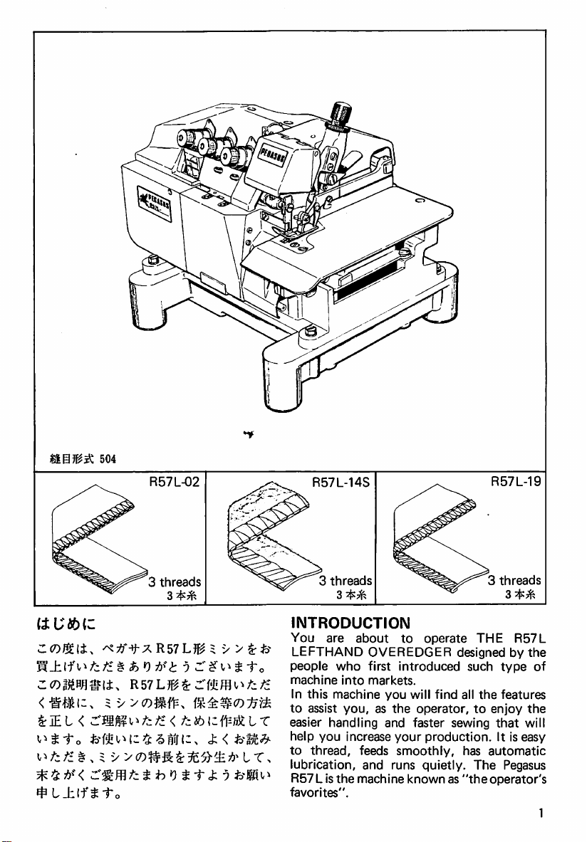
504
R57L-02
3
threads
R57L-14S
3
threads
3^^
R57L-19
3
threads
3^^
INTRODUCTION
You
are
^lEL
<
^^fzfz § , = y
^
L±lf^
to
§
i)
0
1
<
7^i6i;fWLT
J
I'o
LEFTHAND
about
people
machine
In
to
easier
help
to
who
into
this
machine
assist
you,
handling
you
increase
thread,
lubrication,
R57 L is
favorites".
the
to
OVEREDGER
first
introduced
markets.
you
will
as
the
and
faster
your
feeds
smoothly,
and
runs
machine
known
operate
THE
designed
such
find
all
the
operator,
to
sewing
production.
has
quietly.
as
"the
The
R57L
by
type
features
enjoy
that
It
is
automatic
Pegasus
operator's
the
of
the
will
easy
1
Page 3
TABLE
1.
Organization
2.
Run
OF
machine
speed
3.
Machine
4.
Driving
installation
motor,
CONTENTS
chart
at
recommended
pulley
and
Page
belting
Page
2
4
4
4
16.
Regulating
Selecting
Changing
17.
Adjusting
18.
Adjusting
stitch
length
eccentric
eccentric
feed
height
feed
tilt
20
20
20
22
22
5.
Screwing
6.
Lubrication
To
fill
To
drain
Oil
filter
7.
Needle
8.
How
to
9.
Threading
10.
Regulating
11.
Pressure
12.
Regulating
13.
Replacing
14.
Replacing
15.
Knives
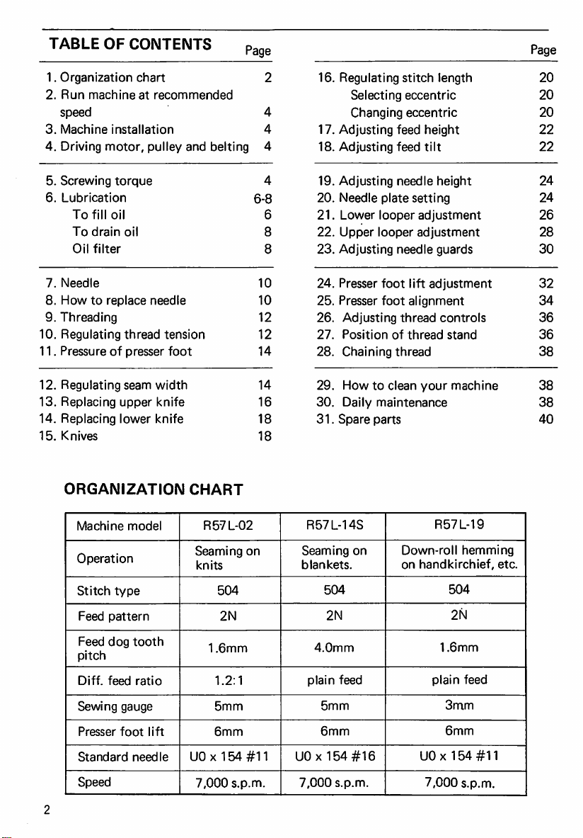
ORGANIZATION
Machine
Operation
Stitch
torque
oil
oil
replace
needle
thread
of
presser
seam
upper
lower
model
type
tension
foot
width
knife
knife
CHART
R57L-02
Seaming
knits
504
on
6-8
10
10
12
12
14
14
16
18
18
4
6
8
8
19.
Adjusting
20.
Needle
21.
Lower
22.
Upper
23.
Adjusting
24.
Presser
25.
Presser
26.
Adjusting
27.
Position
28.
Chaining
29.
How
30.
Daily
31.
Spare
R57L-14S
Seaming
blankets.
504
needle
plate
looper
looper
needle
foot
foot
of
thread
to
clean
maintenance
parts
on
height
setting
adjustment
adjustment
guards
lift
adjustment
alignment
thread
controls
thread
stand
your
machine
R57L-19
Down-roll
on
handkirchief,
hemming
504
24
24
26
28
30
32
34
36
36
38
38
38
40
etc.
1.6mm
plain
3mm
6mm
UOx
7,000
2N
feed
154
s.p.m.
#11
Feed
pattern
Feed
dog
pitch
Diff.
feed
Sewing
Presser
Standard
Speed
tooth
ratio
gauge
foot
needle
lift
1.6mm
1.2:1
5mm
6mm
UOx
7,000
2N
154#11
s.p.m.
4.0mm
plain
5mm
6mm
UOx
7,000
2N
feed
154
s.p.m.
#16
Page 4
s
^
1
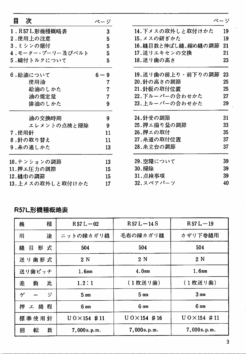
.R57L1^M«^
3 . 5 y vco^-f^
4
.^-9--
-f~
-
y"
3
5
5
h
5
5
14.T^
15.
;^ X COW
16.M@l<fi#(^LM>liMcoM
17.31';
Ji^-t>co3c^
18.3^';iiiCOi^$
§"
75^
i'i
i
Wft
75^
V
19
19
21
21
23
l&VftCO
t
8.#i-C0^«9#^
9.^(Dmi-A'fz
10.T
y y a y
(DM'B
11.#J^l±;fl<7)MSi5
12.Mltico|)^gif
IZ.±.^
7^<DW\-LtM\is\ii3^tz
m
^
u m ^
m
- y hcOft:^
3i
R57L-02
504
6-9
7
7
7
9
11
11
13
13
15
15
17
if^)M.
lo.jM'iiifcoir^o • MT';coiisigi!
20.thcoi^$coMgi5
2i.m&(Dmmm
22.~f
}\/~y^—(D'ah^^^fz
23.±)V-^^-(D^h-^^-rz
24.tt-^col)J10
26.#J:.(7)|X#
27.^)1
CO
WfiM
28.^3i-^(7)M0
29.^i|(;ov^T
30.
Z2.y.^7^^-y
R57L-14S
504
R57L-19
504
23
25
25
27
29
31
33
35
37
37
39
39
39
40
2
1.6mm
(1
tiCT^
0X154
7,000s.
N
•;"®)
3
mm
6
mm
#11
p.m.
m^)
M^)
m
w
li
^
[H
mm
m^ y ^
hj
— y
^
m
15
^
it
m
M
1^:
U
2
1.6mm
1.2:1
5
6
0X154
7,000
N
mm
mm
s.
#11
p.m.
(1
U
0X154
7,000s.
2
N
4.0ram
i!$t3M
■;
®)
5
mm
6
mm
#16
p.m.
U
Page 5
RUN
MACHINE
RECOMMENDED
1.
Do
not
run
5,000
s.p.m.
2.
At
the
end
should
be
Thereafter
operated
3.
Oil
two
of
seizure
at
level
should
lines
lubrication
of
AT
SPEED
the
machine
for
first 4 weeks.
of 4 weeks,
drained
the
machine
normal
speed.
be
always
on
Oil
Sight
may
parts.
out
cause
at
more
original
and
replaced.
may
kept
between
Gauge.
accidental
than
oil
be
Lack
DRIVING
BELTING
Each
machine
belt
of
the
1.
Clutch
watts
{1/2HP).
2.
Belt: V belt,
3.
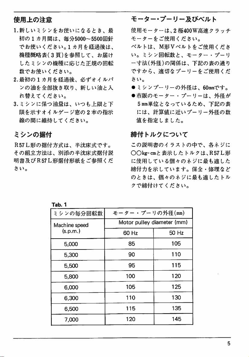
Motor
pulley:
Machine
Motor
measured
MOTOR
should
following
motor: 3 phase, 2 pole,
Type
Pulley
Pulley
at
its
PULLEY
use a motor
specifications:
M.
as
shown
in
Table
Diameter
Diameter
outer
is
60.0mm.
should
diameter.
AND
1.
and
400
be
MACHINE
This
machine
submerged
effortless
The
contained
includes
pattern
installation
operation.
details
in
the
sheet.
INSTALLATION
is
designed
for
are
shown
shipping
sketch,
in
container,
description
for
semi-
efficient
the
and
Manual
which
and
SCREWING
The
figures,
illustrations
represent
when
the
tightened.
parts
recommended
that
the
tightened
TORQUE
which
and
the
relating
For
described
to
relating
with a correct
are
shown
expressed
correct
fixing
screwing
screws,
bolts
the
in
this
use
torque
screws
or
torque
in
by
'xxkg-cm',
torque
or
nuts
main
moving
book,
it
gauges
nuts
can
specified.
the
are
is
so
be
Page 6
i^m±<Dykm
^7}<Dl:^n
^t«l3&^(3H)^#{!^tT,
I
fz^i/ y co^@
2.
MW<7y
ti*^^x
3.
^
Pallia
lij^
<
)^'y—yW^(D
r^vzmnix
^^5000~55001Il#f
(;iS?
<fz^^^o
l;
fz
iEMco
015
'Z^-ft
^
vi-:?^j±i5IiT
^ - ^ - •
7'-«;
-:5lt>X;i/
f5^m^-^-(i.2ti400Wf^jti^
^)y V It.
v^o 5 V
u^v^)y V ^
>01515:i.
^-^7--7°-'J
Tieco^coMO
• 5 V
•
>
';
-OH^i(±^
rliMO^-^-
\Z\t.
imiil-55v^7°-U-mSOS5c
•
L5co
y-'J-|±.
eOmmT-To
N
y-j^
<tz^
^>>(Dmn
R57L?^cO$g{t:^^(±>
H^®At>'R57L?^}g#?F^gc^3:'#0^<
^
v^o
Tab.
5 y 7
Machine
^i:fcJ^^1?1-o
1
<7)^35-01515:
speecJ
(s.p.m.)
5,000
5,300
5,500
5,800
6,000
6,300
6,500
7,000
/i
^—^—'
^;^':7(cot^T
<ros^0;?#c7)^ 7 7
OOkg-cmi^^t/i
i;fs!!ffl L T
CDitJi.
7°—'J
Motor
pulley
60
Hz
85
90
95
100
105
110
115
120
-510^
ji^^CD^-.
CD^'RKmra)
diameter
(mm)
50
105
110
115
120
125
130
135
145
hopf'TN
h
;W7i±.R57L5^
CD y {I®
vdfttiiL/i
Hz
L
h^L'
Page 7
LUBRICATION
The
oil
was
when
shipped.
supplied
ing.
oil
Use
recommended
drained
or
from
Fill
Oil
equivalent
Pan
before
type
the
with
oil
only.
machine
factory
operat
To
fill
oil:
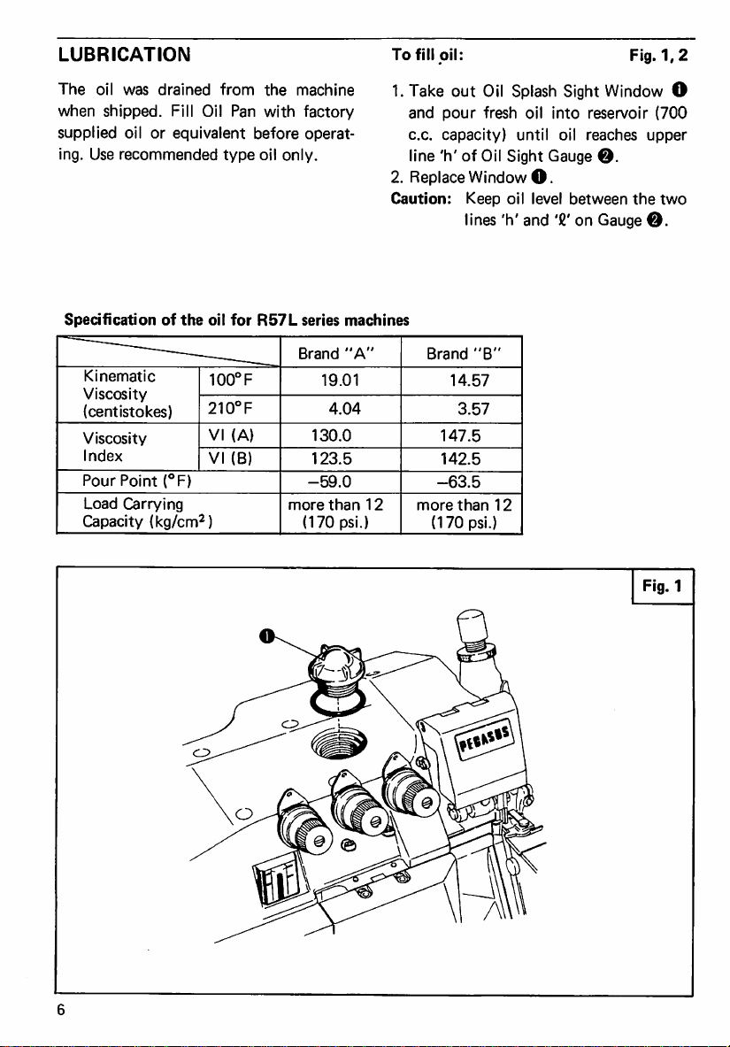
1.
Take
out
and
pour
c.c.
capacity)
line
'h'
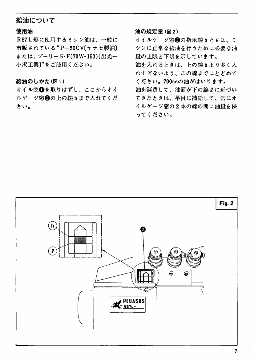
2.
Replace
Caution:
Oil
fresh
of
Oil
Sight
Window
Keep
oil
lines
'h'
Splash
Sight
oil
into
until
oil
Gauge
O.
level
between
and
'8'
on
Fig.
1,2
Window
reservoir
reaches
upper
©.
the
Gauge
©.
(700
two
O
Specification
of
—■—
Kinematic
Viscosity
(centistokes)
Viscosity
Index
Pour
Point
(°F)
Load
Carrying
Capacity
(kg/cm^)
the
oil
for
100°F
210°F
VI
VI
(A)
(B)
R57L
series
Brand
19.01
130.0
123.5
-59.0
more
(170
machines
"A"
4.04
than
12
psi.)
Brand
more
(170
14.57
147.5
142.5
-63.5
3.57
than
psi.)
"B"
12
Fig.1
Page 8
mmm
R57Lj^lzimt6
i
7°-'J-S-F(70W-150)Cai:)fe-
:t>f
)l^Y-
v^0O±CO^
I
y
"P-SOCVC-V-f
ZZ:^^ht4
h t XAhX < ti
(1^2)
t ^ )\/Y-
yyizJE^^
M<7)±m
<
fz^
T§^ci§i±.
oT < /i ^ <^^0
yW,0(Dm^m h i
t
700cjc.(7)ifi;6^"|±Vi
L T Vi ^ -To
±(D^h^iO$rix
Z(D^tX^lzt
0 ^ 1"o
-^-SCli^^LT.
jg
(i.
t'ibX
Fig.
5
^
2
PEGASUS
R57L
Page 9
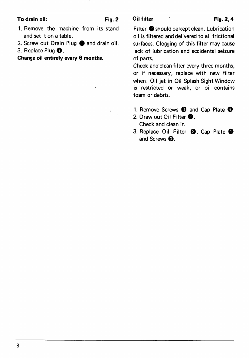
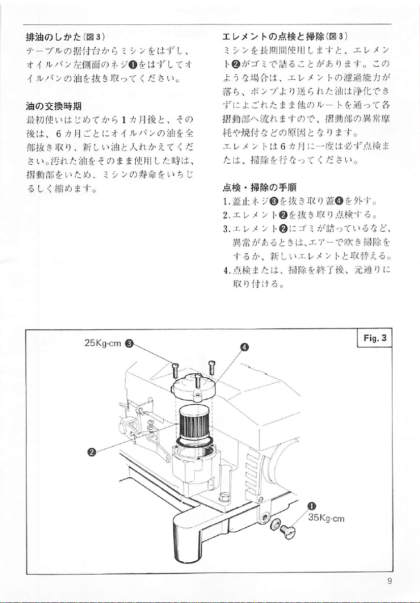
To
drain
1.
Remove
and
2.
Screw
3.
Replace
Change
oil:
the
set
it
out
Plug
oil
entirely
machine
on a table.
Drain
Plug O and
O.
every 6 months.
from
Fig.
its
stand
drain
oil.
2
Oil
filter
Filter 0 should
oil
is
filtered
surfaces.
lack
of
of
parts.
Check
or
if
when:
is
restricted
foam
or
1.
Remove
2.
Draw
Check
3.
Replace
and
and
Clogging
lubrication
and
clean
necessary,
Oil
jet
in
or
debris.
Screws © and
out
Oil
and
clean
Oil
Screws
0.
be
kept
clean.
delivered
of
this
and
accidental
filter
every
replace
Oil
Splash
weak,
Filter
©.
it.
Filter
0,
Fig.
Lubrication
to
all
frictional
filter
may
seizure
three
months,
with
new
Sight
Window
or
oil
contains
Cap
Plate
Cap
Plate
2,4
cause
filter
O
O
Page 10
(0
3)
t 4 ;b/x° > £#JlS<0
4
b 5 V > ^l±-f
vO^lt-f L T
L,
xiy^>
5
^
hOTlj^'r'A
J;
KC7);i^^i:J§l^(0
V V & i^wifiofs
9
ni
JZU
bi-ri,
t
;<
y
3)
t
xb^v
Ao
bCO
f^[±,
•& L <
%iinxt\zii^
rrtvMftiAn:^'^r
its()S-ro
</i
-fizJzXhfzt
SftlicoJU-
MHjSii^i^nS-fc?)T^
xu^vMieT:?!^
fzit.
1.m±x
2.xu^
>
3.xu^ > !>@i;=7A
i±,
Ifrbi^xu^
A(i.
m'oiii-f^o
h
[i;'£'f,-;.it^^
<
fz^^-^o
XT - Tnx ^ Jf ^ ^
>
Ttm^iz
Page 11
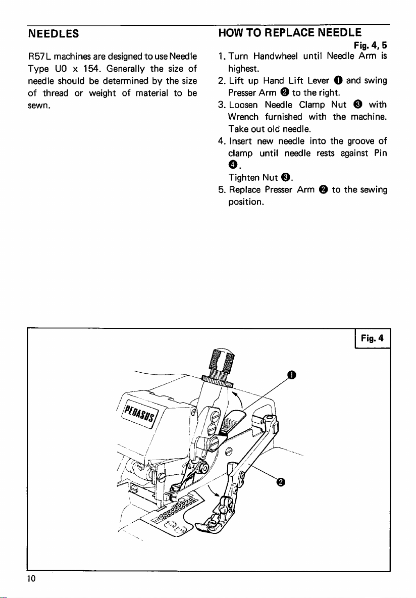
NEEDLES
R57 L machines
Type
DO x 154.
needle
of
thread
sewn.
should
or
be
weight
are
designed
Generally
determined
of
to
use
Needle
the
size
by
the
material
to
of
size
be
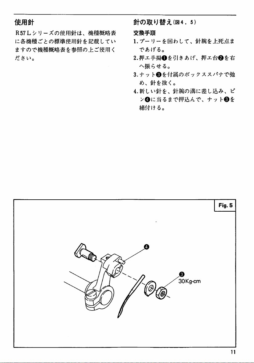
HOW
TO
1.Turn
highest.
2.
Lift
Presser
3.
Loosen
Wrench
Take
4.
Insert
clamp
O.
Tighten
5.
Replace
position.
REPLACE
Handwheel
up
Hand
Arm e to
Needle
furnished
out
old
needle.
new
needle
until
Nut
©.
Presser
until
Lift
Lever O and
the
Clamp
with
into
needle
Arm 0 to
NEEDLE
Needle
right.
Nut 0 with
the
machine.
the
groove
rests
against
the
Fig.
4,
Arm
swing
sewing
5
is
of
Pin
Fig.
10
4
Page 12
mmm
R57Ly
t
fz $ V^o
:r't
coiiSf^
^
ffl
it ^ iei( t r
^ mM<D±z'im
ti-<?)|RU^X(l2l4.
1.7°-U-^0hLT.
<
•ti"
-5
o
3.^7
hO^iifB,<D^-K7
i6,
5)
■:^7
h0^
Fig.
30Kg-cm
5
11
Page 13
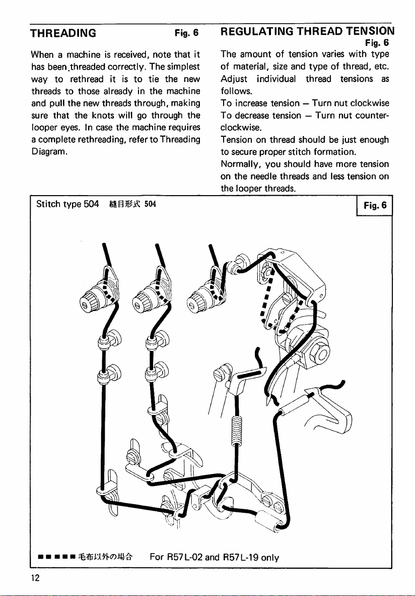
THREADING
When a machine
has
been
.threaded
way
to
rethread
threads
and
sure
looper
a
Diagram.
to
pull
the
that
eyes.
complete
Stitch
type
those
new
the
knots
In
case
rethreading,
504
is
received,
correctly.
it
is
to
already
threads
through,
will
the
machine
in
go
refer
504
Fig.
note
that
The
simplest
tie
the
the
machine
making
through
requires
to
Threading
new
the
6
it
REGULATING
The
amount
of
material,
Adjust
follows.
To
To
clockwise.
Tension
to
Normally,
on
the
individual
increase
decrease
on
secure
the
needle
looper
thread
proper
you
threads.
THREAD
of
tension
size
and
varies
type
thread
tension — Turn
tension — Turn
should
stitch
formation.
should
threads
have
and
TENSION
with
of
thread,
tensions
nut
clockwise
nut
counter
be
just
more
less
tension
Fig.
6
type
etc.
as
enough
tension
on
Fig.
6
For
R57
L-02
and
R57
L-19
only
12
Page 14

h
e.
^.mn
0.
MJio/i!
■fo
:^li[2I(7)M0
/ijfi L 75^/l ^ It-to
J: 9 UjfiL S 1*o
i<7)aa%ilZ
UIEL < Mtr
x> V a
It
<
ir<Dx\
•y
hT-S^lfft
C
co^i-^.
T.
■f
n(f
><7)ilS5(ii6)
T < fz
^
^^s(Dt
CO
y y ay
b
tit
t
IK
J: 9 Ull^gfi
to
(B)co_hco@7t76^b,
J; 9 Iwiili L i
504
R57L-02
l+^)i(C)co@
-fo
R57L-14S
R57L-19
13
Page 15

PRESSURE
Pressure
means
Screw
Pressure
enough
stitch
spoil
than
cause
1.
2.
3.
of
of
®.
on
to
formation.
material
it
needs.
uneven
Loosen
To
increase
Turn
To
decrease
Turn
After
obtaining a proper
tighten
OF
PRESSER
Presser
Pressure
Presser
feed
Lock
Screw 0 clockwise.
Screw 0 counter-clockwise.
Foot
Foot
material
Too
and
give
Too
feeding
or
Nut
0.
pressure:
pressure:
is
Regulating
and
much
it
little
stitches.
FOOT
Fig.
regulated
Thumb
should
be
obtain
proper
pressure
more
stretch
pressure
7
by
just
may
may
pressure,
Nut
0.
REGULATING
The
position
needle
regulates
1.Turn
2.
3.
4.
5.
6.
7.
Handwheel
at
its
lowest
Loosen
Push
right
tighten
Loosen
and
the
obtained.
Tighten
Loosen
will
Tighten
Lower
Lower
as
screw
Upper
move
right
screws
screw
return
screw
of
Upper
the
position.
Knife
far
as
O.
Upper
or
left
to
position
O-
SEAM
Knife
seam
until
Knife
Holder
Holder 0 to
it
will
Knife
Clamp
Knife
until
desired
0.
O,
then
by
WIDTH
to
the
width.
Upper
Knife
Screw
go
and
Screw
Clamp O to
width
the
Holder
spring
action.
Fig.
8
inside
is
O.
the
lightly
0
is
0
y
Note:
Needle
widths
are
obtained
proper
width
required.
Plates
are
available.
size
Needle
for
with
various
Best
use
Plate
for
seam
results
of
the
seam
Fig.
7
14
Page 16

^X-h-'h.
1"o
V-y 9 i--y
A'7
7°0lrlHl
;^f
^(,^0
LT?f
^rt]0pgi5(ia8)
1.7°-';-^[llLT.
X^M^o
±^^yO^UUir^o
3.fS^;r^y©^§ii6.
-t^T.
7
:5">l
±><XJS^O^M
i
^/i
L;&^i6.
Fig.
25Kg-cm
e
'i25Kg-cm
8
15
Page 17

REPLACING
1.
Loosen
2.
Push
Lower
right
as
tighten
3.
Remove
Wrench,
and
4.
tighten
5.
Turn
screw
withdraw
Replace
screw 0 completely.
Handwheel
Clamp O is
6.
Set
the
overlaps
as
shown
©
securely.
7.
Loosen
will
return
8.
Tighten
THE
Lower
Knife
Knife
far
as
it
O-
Upper
furnished
with
blade
Lower
screw
screw
Knife
knife
new
at
its
so
Knife
in
Fig.
O,
to
position
O.
lowest
that
UPPER
Fig.
Holder
Screw
Holder 0 to
will
go
and
Screw 0 with
with
the
machine,
downward.
knife
but
until
Upper
position.
its
cutting
by
0.5 — 1.0mm
10.
Retighten
then
the
Holder
by
spring
KNIFE
9,10
O.
the
lightly
do
not
Knife
edge
screw
0
action.
Fig.
©
30Kg-cm
25Kg-cm
16
9
Page 18

(1219.10)
l.ii:^>
2.±^-«y©^Jfe^0.
■to
3.rrtv^±^
m±ib-t6o
4.y-';-^0LT^
.>5 i T- ^ (f\
_h^ X <h T ^ ^ ;!)noigl(7)
J: 9 l:i0.5~1.0inin;6'tf^'^
^
^^h-itX^
jh^-y'O^liii'f^lt'So
5.±;t^y0^5ifei6'5o
•y 9 ^)
fz
Z. t ^
T
"a0Irfii"t
±^X^|XO(ir
±^>y0T-
9
±/
fz I ^'ib.
^
^
jh
Fig.
10
Upper
knife
X
Needle
top
fi-IH
plate
surface
l-Jfn
0.5~
I.Onnm
\\\\\\\\\\\\\\\M
Lower
knife
X
17
Page 19

REPLACING
1.
Loosen
2.
Push
Lower
right
as
tighten
3.
Loosen
and
withdraw
4.
Insert
Clamp,
cutting
of
Needle
Tighten
5.
Turn
Handwheel
Clamp O is
6.
Loosen
will
return
7.
Tighten
THE
LOWER
Lower
Knife
Knife
Holder O to
far
as
it
will
screw
O-
Lower
new
setting
screw
knife
edge
Plate
at
Knife
knife
the
is
level
as
®.
until
its
lowest
downward.
into
blade
shown
screw O then
to
position
screw
O.
Fig.
Holder
Screw
go
and
Clamp
Screw
Lower
so
with
in
Upper
position.
the
Holder
by
spring
KNIFE
11,12
lightly
Knife
that
the
top
Fig.
Knife
action.
O.
the
O
the
12.
0
KNIVES
Knives
may
while
is
Upper
tors
since
carbide
sharpened
must
be
sharpened
making
maintained
Knife
or
return
it
is
alloy
by a diamond
be
kept
by
sure
that
as
shown
may
be
to
made
from a special
material,
sharp.
use
the
in
Fig.
sent
to
us
for
and
grinder.
Fig.
13
Lower
Knife
of a grinder
correct
angle
13.
our
distribu
resharpening
tungsten
must
be
Fig.
25Kg-cm
18
O
25Kg-cm
11
Page 20

(011.12)
.><X0?3Ft>/=(013)
2.i--y
h®^§l646,
XDf^lz^ljh^s
±mt.
b-a-T.
T^xc7)^5fe^l0li;;^$(C'&
i-y
4.7°-•;-^®
5.±;T>
vOiSr^ifeto-So
7
^'J
Vimo-)^ 0 \z%\Wi
h©^lii5#{t^o
LT.
ii^x^O^T^
i
Fig.
^
12
^■t(DX\
<
ti
^\^o
aT^
tT^
A_h^xii,
LT.
tzt-^.
li,
tXo
<r h VMiSff
T^^^fiffri£LT<
IEflil-5ffViT'<
#31(7)^*7
^ f C ^ h
;'K-Ii^ft(7)±^
5ffrii:t
-f
^
Li-to
1^(;©gP(;
13@^#0S
v^o
^
ttz
Fig.
t
13
ys*"
Upper
Needle
top
surface
ft-tS±ig
ESSSSSSS,
Lower
I
yy
plate
knife
<
X
knife
-±^
X
0,5 ~ 1.0mm
19
Page 21

REGULATING
Stitch
combination
eccentrics
actuates
Inner
The
indicates
However,
or
Selecting
When
feed
that
material
When
feed
that
material
Changing
1.
2.
length
of
to
be
differential
eccentric O actuates
number
less
stamped
the
number
the
stitches
depending
eccentric
the
stamped
eccentric
of
main
feed
will
tend
the
stamped
eccentric
of
main
feed
will
tend
eccentric
Remove
Crankshaft.
Screw
machine,
Feed
R57L-14S
Nut O and
extractor,
into
Eccentric © (Spacer © for
and
STITCH
is
determined
main
and
differential
used.
Outer
feed.
on
of
stitches
made
upon
the
number
(e.g.
#8)
is
eccentric
to
shrink
number
(e.g.
#14)
eccentric
to
stretch
Washer @ from
furnished
screwholeof
-19)
and
take
LENGTH
Fig.
14,15
by
eccentric
main
feed.
feed
eccentric
per
inch.
may
vary
more
material.
of
differential
smaller
(e.g.
#12),
in
stitching.
of
differential
is
larger
(e.g.
#10),
in
stitching.
Fig.
14,15
with
Differential
it
out.
the
feed
©
than
than
the
3.
Screw
Main
for
out.
4.
Be
are
Clean
dirt
the
5.
Face
(rightward)
extractor
Feed
R57L-14S
sure
to
clean.
Eccentrics
and
dust
machine.
the
into
screw
hole
Eccentric O (Eccentric
and
-19)
and
take
Eccentrics
deposits
extruded
and
and
in
oil
before
portion
insert
mating
to
remove
placing
outward
Main
Eccentric O (Eccentric © for
R57L-14S
mating
crankshaft
6.
Face
(rightward)
Eccentric © (Spacer ® for
and
groove
7.
Replace
8.
Tighten
the
the
-19)
with
Washer
Nut
and
-19)
eccentric
key.
Use
extruded
and
insert
in
the
crankshaft
the
key.
©and
O.
on
the
crankshaft
groove
with
extractor.
portion
outward
Differential
R57L-14S
mating
Use
extractor.
Nut
O.
Fig.
of
©
it
parts
all
in
Feed
the
Feed
the
14
O
35Kg-cm
20
Page 22

(7)iili5(®i4,
'J
j:.^-tr
15)
><Dm<On^\~^iO
^S!B[(7)iS85
iH
'J
-I- ^ -t > (I
8 i l^p
(±>
12t|-coM@
-fe
>
IfeJtilcofilIMm;
li,
^nXi^tXofzt
ntz:^
, 12<hP|J$n/i
f'ii/IK/i ^ (,^0
oTMlElSi(l±,
Xo
iss«)^a)Pgi5
XJl
•;
(DJz^-b
#
{f L M11 ^ S
fOiW
<
CO
3^
'j
>
liX-2<l-::X
mm
[IIEi3{3M
25mmll!]c7)^g
25mmfiJllC8if
^
-f o ^!eM-^X
.
i-o
XXill^XfM Ub-
XifeS'l*,WII ? ->
LX ^ >0
^
J-^-t
fz/zl.
mDjM
iim
tXo
(±\
>
'J
5i';iJe-ti><7)5^i^(isii4.
1X^McOX/n°XX-3MO
O ^ ikM n ;M<fe0 ^ li
2.Um(DJL^-t
>fk^
X'X
15)
>jhX-y
o
^0j3^ 0 J. ^ -t > © • X3^ U j:. ^ -t
o
^
-s
o
•
R57L-14S
ij
7-0 • 3^ U +
X3M'3
X3M';
JcJr-t
4.m!})M 0 J- ^ -fc > ©COMPP ^ HfltiJ
It,
^>®J3^
zli tt
CO ^ ^
5.
rM^e
• 5 V
•
>liX^f-J-(t-5rrLc^3^'J
l±,
nliX'X < ?3ti^,
3^
'J
-I-
tr
(4lM)l-5?i'5cc03^'J-x + -t
Tc^SXCOX,
•
R57L-19C0^^-^|±,
>@SrtfeIlX-5o
>OcoMPP^3'M!!ijl-i^5]{t,
>OcO^-?iSf^<i:,
T#3At;>o
•;
jc ^ -tr
>0£7)
tr - ?iVji
ft
-t
<
>(±.
/i
h-It T t>l'iZi
$:
c^o
3^ 0 tr
hO^
o
$«ft
J-tr-t
-t > —
x^geiiKL
3i
0-xtr-t
>—
X^ilico
t;
{t
#nS(0Xrrfi1ij < /i $ c^o
h
>
[fi]
,
-5
o
>
Machine
model
^
R57L-02
R57L-14S
R57L-19
fjti
in
machine
Main
= V >cOx^-tr
:!•
31
U
#12
#
#6
eccentrics
Diff.
#10
5
>
u
in
acc.
box
ft-®
CO
X:^-fe
#8
#14
#5.5
#7,
>
#8
Fig.
Feed
35Kg-cm
15
21
Page 23

ADJUSTING
R57L-14S
Standard
above
at
its
1.
Loosen
2.
Turn
3.
Move
Tighten
R57L-02
Standard
mm
at
its
Differential
straight
of
1.
Loosen
2.
Turn
3.
Set
then
4.
Tighten
5.
Set
are
Feed.
and
height
the
top
back
tooth
Screw
Handwheel
Feed O as
Screw
height
above
the
back
tooth
edge
Feeds.
Screws O and
Handwheel
Main
Diff.
Screws O and
Auxiliary
0.5mm
FEED
R57L-19
HEIGHT
of
Feed
surface
when
e.
of
Feed
until
Fig.
Feed
required.
0.
of
Main
Feed
top
surface
when
Feed
should
can
be
Feed 0 first
Feed
©.
Feeds
placed
0.
until
Feeds
of
be
as
©.
Feed 0 so
below
from
16,17,18
is
1.0-1.2mm
Needle
is
highest.
is
highest.
is
1.0-1.2
Needle
are
highest.
set
so
that
across
the
are
highest;
required
that
its
those
of
Fig.
Plate
Plate
a
top
and
teeth
Main
16
ADJUSTING
Feeds
are
factory-set
Feeds
are
level
above
the
top
By
this
setting.
back
tilt
or
higher
rear,
when
Feeds
Generally
Feeds
Knit
Woven
1.
Loosen
2.
Turn
3.
Turn
set
are
highest.
material;
material;
Lock
Handwheel
Pin © until a proper
obtained.
tightening
strongly
the
Note:
inward
sidewise
When
is
necessary
height,
FEED
surface
Feeds
Feeds
front
(Standard).
level.
so
when
in
are
highest.
to
TILT
that
they
of
will
the
as
back
Screw © for
until
Feeds
Tighten
Screw
play
the
®,
in
in
Feed
feed
Screw
order
tilt
to
too.
Fig.
the
teeth
first
appear
Needle
Plate.
have a front
front
than
follows
tilt
Pin
0.
are
when
highest.
tilt
©.
When
press
Pin
to
eliminate
Bars.
is
changed,
adjust
the
Fig.
19
of
to
the
is
©
it
feed
17
1.0 ~ 1.2mm
/
22
McT^V
mm
20Kg-cm
Page 24

jM
'J
TWtt^
1
$(016.
17,
T^'1.0~1.2mra(I'^-ti-
to
(R57L-14S • 19)
18)
511
•;
m0m±
tStijiSL/ci
®
mm^m
1. fc:°
t ^
>± t V®
<D
u
hut
0±#L.
omm
±X(DM9cti^U±
75^^^
^?ife46
^o
Jt
(019)
T't
o
0.
mm|;-^-ti-T±t
2ft5MUii-&
l.ii)i';ii[0^±T(cilj7{;^-ti:.
j:0.iMU®f^gP(7)li^St'1.0-1.2
ra
ni|I'^-ti-T±t
2.
HiJlji
^
b ^ Is]
^l3^:.tLT0.5mmTt;^lf^
(R57L-02)
'J
]t®CO
b'
vO^ISf^tt
iif5fe ^ ±)M
^
T'.
'J
> ± t
1.0-1.2
-So
^■m±m
6o
(iOc')))!
vO
to
Fig.
18
•
3
if
c^3^1fb(^m)cOli'^liHtTlCLJto
CO
ii; ^ c7)
i]^)y
LottTiht
^ff
0
rjigif
ifl?±0
O
i § li.'iJ't.iM'l
tf
9
f: L ^
v®^^i6T<
25Kg-cm
o i to
to
tfz.
K0l§lfe^7&^'®
Fig.
19
®25Kg-cm
25Kg-cm
23
Page 25

ADJUSTING
The
needle
machine.
from
surface
highest.
careful
Needle
of
1.2mm
needle
1.Turn
2.
3.
4.
This
the
of
When
to
is
Needle
apart
hole.
Handwheel
highest.
Loosen
Drive
Arm
Move
Arm e and
of
Needle
Tighten
NEEDLE
height
height
point
Needle
making
set
Needle
centered
Plate
from
Clamp
©.
as
required.
Screw
HEIGHT
is
10.3mm
means
of
Plate
and
the
Needle
as
in
the
to
when
this
adjustment,
shown
the
needle
its
front
bottom
until
Screw O for
make
the
O.
Fig.
20,
for
this
distance
the
top
Needle
in
Fig.
hole
edge
of
Needle
Needle
position
21
is
be
21;
is
the
is
NEEDLE
As
shown
centered
Plate
edge
bottom
setting),
Sidewise
This
no
further
PLATE
in
Fig.
in
the
(sidewise
should
setting
be
of
the
when
it
setting
is
correct
adjustment
setting),
needle
is
Bracket O has
reason.
1.
Tentatively
O
with
key
in
the
2.
Loosen
Move
required.
Tighten
Front
to
When
always
1.
Loosen
2.
Move
required.
Tighten
set
Screws
of
Bracket O fits
bottom
surface
Screws
Bracket O right
Screws
back
setting
fixing
Needle
keep
this
setting
Screws © for
Needle
Screws
SETTING
21,
Needle
needle
1.2mm
hole
lowered.
at
is
been
Needle
©,
©.
©.
Plate
correct.
Plate
back
©.
Fig.
should
hole
of
and
its
apart
from
(front
the
factory
required
moved
Plate
making
of
on
sure
in
the
Needle
for
or
on
machine,
Needle
Plate.
or
front
21,22
be
Needle
front
the
to
rear
and
unless
any
Bracket
the
groove
Plate.
left
as
as
Fig.
20
Fig.
10.3mm 1 \/
o
35Kg-cm
24
21
Page 26

t § ^
^
T\
Mii!l3}fi!loT>
X^-fo
1.x-
ifmmm X V
2.tf-|r ^ (fXz t ^
'C.»^iE?it-A-5
Wj/)^LXmBt6o
3.
7°-
'; - ^
o
HI L T
Mii!(-}B!l-oT^
X y O
^
1+15±IS
ci:
0
10.3mm;6^'^^"\l'?i
imt 6 o
J: 9 ,
A/i
/i
t>'f+
^
10.3nini|;'^h t T ^ t+
t+
-5
o
22)
^
21110+; 9 I3#+|S a J; 0 1.
li-??|«+>'C.'
tto
X
2.7°-'j-^ULT,
3,
ti-
M • ^:^r^<7)is@s
l.±+^y©^ll<rai--5o
2.l1-+5^Mf^t-i)!l?&'L > a
yO^UUt^o
b
aV.S
b
,'^,{l|+;6^+ig-t-
4"C.^
5
16tZ6tX\
,#.+;
1.2mmt;'^h L T.
iffz t ^
2minM:^0
J; 9 ^#{t
$
tf-So
±+^v@
Of+i+^'C,'
±+-
v©
s
Fig.
20Kg-cm
©
25Kg-cm
22
25
Page 27

LOWER
When
Lower
its
point
should
centerline
Also,
the
Looper
Needle
in
Set
the
apart
and
the
scarf
Looper
center
from
you
(0-0.1
can
LOOPER
Looper
be
of
Needle.
mm
of
Needle.
as
its
of
Needle,
make
ADJUSTMENT
is
extremely
5.3mm
point
clearance)
point
Needle,
when
this
apart
should
in
the
and
Needle
adjustment
Fig.
from
just
when
rear
0-0.1
is
23,24
right,
the
touch
it
is
and
at
mm
lowest,
easily.
1.
Insert
Looper
far
as
it
Tighten
rests
against
Looper
2.
Lightly
Looper
3.
Turn
Handwheel
4.
Move
Lever 0 as
Turn
Handwheel
from
the
centerline
extreme
If
necessary,
for a fine
5.
Tighten
into
will.
go.
Screw
O.
the
shank.
loosen
Lever
right
Clamp
0.
Looper
be
5.3mm
position.
move
adjustment.
Screw
0.
Looper
making
flat
Lever 0 as
sure
its
portion
head
of
the
Screw 0 for
until
Needle
is
lowest.
required.
and
check
the
distance
point
to
the
Needle
at
Looper's
Lever 0 just a little
Fig.
5.3mm
"025Kg-cm
-07OKg-cm
26
23
Page 28

^i^iH-COPf.PBKiO-O.lminC-g'b-ti-Si-o
(D y ^ 0 i;±
2.mU^^yO^^<UUi'^o
3.
7"-'j
-1:® L T,
^
Hi:.
"F
^
h-it
^o
-
-It^o
5.
_hieO~
^M
t <7)Pf,Pt}]
0.
IramW
"t
J;
0.
ti-4"i:^
vO
(t 6 o
#i'^"f^.'?i'.l-ii®
® ^ ^ i -
^0-0.
^
lniml^-^b
L
i-C-5.
3mm(l
tz
>
;u-
h
0.1mm
Fig.
24
27
Page 29

UPPER
When
should
the
centerline.
When
Looper,
without
Clearance
1.
LOOPER
Upper
be
Looper
Upper
they
striking.
Insert
Lever
the
back
right
edge
Lightly
2.
Lightly
Upper
3.
Turn
Handwheel
4.
Move
Crank © up
the
distance
mentioned.
5.
Turn
Handwheel
that
the
Looper
the
distance
eye
center
Looper
should
(Clearance
'B' = 0.2mm)
Upper
and
tighten
loosen
Looper
preset
edge
of
Looper
Screw
Lever
Looper
'a'
Clamp
until
clearance
ADJUSTMENT
Fig.
is
highest,
of
3.0mm
and
the
crosses
be
as
near
'A' = 0.5mm.
into
the
clearance
of
Looper
Lever
O.
Screw O for
Crank
Looper
or
down
of
3.0mm
slowly
'A'
is
0.5mm.
and
25,26.
there
between
Needle
Lower
as
possible
Looper
from
to
at
4.0mm.
©.
is
highest.
and
obtain
above-
observe
27
the
6.
When
clearance
0.5mm,
Turn
Handwheel
Move
Looper
3.0mm
Turn
clearance
7.
When
move
highest
and
abovementioned.
Turn
clearance
8.
clearance
9.
When
tighten
distance
Handwheel
clearance
Crank
obtain
Move
Looper
the
Screws O and
point,
Handwheel
move
until
inward,
abovementioned.
'A'
is
0.5mm.
'A'
downward.
move
the
'A'
is
0.5mm.
in
'B'
is
0.2mm.
above
'A'
is
more
than
Crank © upward.
Looper
is
highest.
and
obtain
the
again
and
check
the
is
less
than
0.5mm,
At
Looper's
Looper
3.0mm
and
its
holder
setting
outward,
distance
check
until
is
complete,
the
the
©.
Fig.
25Kg-cm
—4.0mm
©
lOOKg-cm
28
25
Page 30

±.)\/—ji-(0^t>-\tiy'tz
-@yA:4"ll'^
^O.BmmlZ^
±;i/-/N°-a fij;
T'4.0min|;fM(l-^h
<imt^o
2._h;u-yN°_gff^ 7 >
<
MUir ^ o
3.7°-'J-'^|pILT.
.'rApfiS ^ -ti"
4.
_h
;u - ^
i;,
fjT&a,
4''O^T'3.0min(I-^b1-o
-
(DptR{] A >6^'0.
T'S.OmmT'i-o
^0.2nim|I'^b-ti: i i~o
f),
"S*
o
^° - 7!)^'±^,'S
Smint;
(025-27)
LTx
ih^-
vOSr^
±;i^-/>°-$r±5E
CO t ^
cotl"
yy
^e^±Tiz
OT
V^
-S i t'
^
«9,
It
9
6.0.
SmmtU-hCO^^-a
0J-;U_y-?_3fj^ V y
izWi^'i'o
-/^°- ^ ±^,|5
—
CO
jtjffl ^ 3.
T
Pf.
fH] A ;!)fO.
"1"
-So
@0.5mml.U±co<i:§li.
7,0.
Bmml-UT'CO^^'o
l±
C^O^'Pl^±j
Izfjg
Ommi;
5nim
11 ^ o T V i -5
<'9SLM^t
l±
0±;^-/^°-j^^^;7 7 >
izWi^'iTo
;u _ y f ^
tllig $ -tt ^ o
0±;W-/^°-|r'"^l#itiLTj
"ah-f
o
©±
;i/- / N° - i
T.
P^rai A 7!>^0.
El"-So
"F
^
5mmll ^ oT
©O.SmmWTcOi
"f-So
8.
±!e
3.
Omra^i^
t>'0.
5mra ^ t
•r\
B
^0.2tmlZ'^h-\t 6 o
$-It ^ „
i"
o
3.0nim|;
^ ^ ^-tt
Mttl
^
;{)^^
Fig.
3.0mm
26
0.5mm
o / 0.2mm
Fig.
27
29
Page 31

ADJUSTING
Rear
needle
When
Lower
and
at
the
center
Guard
should
deflecting
1.Turn
Lower
center
2.
Loosen
Guard
3.
Move
Guard
deflecting
it.
Handwheel
Looper
of
Screw 0 for
Bracket
Bracket O so
just
Tighten
Needle
deflection
NEEDLE
guard
Looper
of
just
is
Needle.
O.
touches
it.
Screw
point
Needle,
touch
until
in
the
that
0,
making
by
Needle
GUARDS
Fig.
is
in
Rear
Needle
the
rear
and
Rear
Rear
Needle
Guard.
28,29
the
rear
Needle
without
point
at
the
Needle
Needle
without
sure
of
no
Front
needle
When
Needle
a
slight
Needle
and
1.
Turn
2.
Loosen
Guard
Move
Guard
Tighten
guard
is
lowest,
clearance
Handwheel
Front
Needle
(0.1-0.2mm)
until
Screw O for
Bracket
0.
Bracket © so
is
0.1
•0.2mm
Screw
O.
there
Guard.
Needle
Front
that
Front
apart
from
Fig.
should
between
is
lowest.
Needle
Needle
Needle.
29
be
Fig.
30
28
Page 32

tfS(B)
;u-/N°-
0^15
(028,
29)
28[10cI:9I;>
^
T
o
l.t|-^(B)»f^,
6o
T'fJf
i£:
;i/ - /^•-
«<!:
t|-(7)
5n d Pt
0.1 ~ 0.2mm
11
F«1
r.
P0l^O.l~O.2mml-'^^-ti"T,
ih-T-vO
Fig.
29
25Kg-cm0
!
1
j-^
25Kg-cm
O
7
31
Page 33

PRESSER
ADJUSTMENT
Presser
machine.
In
lifted
Foot
by
Foot
other
6.0mm
Lift
Screw
words,
Lever O is
0.
FOOT
Lift
Presser
up
from
LIFT
is
6.0mm
Foot
Needle
lowered
and
Fig.
30,31
for
should
Plate
when
stopped
this
be
6.
Loosen
Keeping
Lever
play
from
Tighten
Screws
O,
clearance
Presser
O.
the
6.0mm
move
of
Arm
Screws
0.
lift
by
lowering
Stopper 0 until
0.3-0.5mm
0.
is
obtained
a
1.Make
2.
3.
by
turning
Loosen
When
Foot
just
Feed
Nut 0 and
Lever O is
Screw © and
of
2mm
from
Tighten
4.
Loosen
5.
Turn
obtained
stopped
Tighten
Nut
Nut
Screw 0 until
by
Nut
Dogs
Handwheel.
begins
obtain a play
Lever
0.
O.
when
Lever O is
Screw
0.
O.
30Kg-cm
below
Needle
Screw
0.
lowered
to
O.
be
the
and
lifted,
6.0mm
lowered
Plate
Presser
turn
clearance
lift
is
and
Fig.
30
O
30Kg-cm
32
Page 34

ff
X±UM0iill5(ia3O.
t^'6.0nimT'i"o
^If^o
2.^7
3.^if
±®J:0.
y©^0
©CT) a t
•y
h©^^#(t^o
0
IfxJS® i T'6.
^_hlf
-So
$
lt\
LTJE^^U^^—Ot
COPf,® ^ 2mrad'^h
30
#x)!s®
OmmCT)
ig $ S
J; 0 .If
LXi'
T'^fx
X
5.6.
OmmCO ^ lit# L ^
T\
1^
@i5
y©^J£^U^<-OC^^cfc 9 CM
L.
t-y
VOiiUUn^o
6.6.
OmmCO
"t
r± ^ lit# L fz
X h 7^'^°-©i^±Tl-ifl7!>^L.
©C0±®
O.SmmOPf,®
#tt§o
l±,
J;
0. X h
7/^°-©^-e0.3~
^-9<
oT^±^-vOl'lifj
t¥x{s®7{)WS_h®
L/illlli.tfx^e.Omm±(ffz
i
V
^cosmM^-v©i.
.
ttp x ^
tix^
-To
Fig.
25Kg-cm
0.5mm
31
33
Page 35

PRESSER
Presser
Plate
with
eliminate
(seepage
1.
Foot
and
that
of
Loosen
Hinge
Spring.
Its
14).
Loosen
Foot
Bracket.
2.
Move
Presser
hole
is
Plate.
3.
With
Presser
Plate,
tighten
4.
After
properly
pressure
14).
FOOT
needle
Needle
the
Screw O for
Clamp
aligned
ALIGNMENT
should
pressure
be
hole
should
Plate.
Screw 0 for
Foot 0 until
with
Foot 0 flat
Screw
0.
set,
on
Presser
Fig.
32,33
flat
on
Needle
be
aligned
For
this
setting,
of
Presser
Presser
Foot
Foot
Presser
its
needle
that
of
Needle
on
Needle
load a proper
Foot
(see
page
Fig.
34
32
Page 36

#1(7)
IX#
i:^<im-r^o
(032.
33)
1S±ffi ^ fef 7 ^ 'J
i
.
±V
Fig.
33
15Kg-cm
30Kg-cm
35
Page 37

ADJUSTING
CONTROLS
Thread
Thread
less
material,
Factory
positions
left.
1.
2.
3.
4.
5.
6.
Controls
Takeups
depending
etc.
setting
when
Lower
Horizontal.
Upper
The
edge
Auxiliary
O:
Its
edge
'C.
Lower
Its
lower
Upper
Lowest
Upper
Highest
THREAD
or
and
Guides
on
is
as
Lower
Looper
Looper
'C
eyelet's
Looper
Looper
in
Looper
in
2.5mm
Lower
edge
the
long
the
long
Thread
Thread
Looper
center
Thread
level
Thread
Thread
the
positions
vary
operation,
follows.
Looper
threads,
Check
is
extremely
Takeup
Takeup
below
Takeup
Thread
level
with
Guide
with
the
edge
Guide
groove.
Guide
groove.
Fig.
more
the
O:
0;
Guide
the
'C.
0:
34
of
or
O.
O;
©:
POSITION
Set
thread
stand
in
Fig.
35.
1.
Loosening
set
thread
2.
Obtain
80mm
Top
3.
Bar o should
front
4.
Tighten
the
between
Cover.
of
Oil
screws
OF
THREAD
in
position
screws
guide
bar O as
distance
bar O and
be
Sight
Window
0,
STAND
as
per
0,
0,
(D
follows.
of
approximately
above
and a little
©.
0, 0 and
Fig.
35
shown
and
0,
Machine
0.
Fig.
2.5mm
36
34
Page 38

(034)
5:^(011115(035)
xp'pm^j-
v(D ^ 7K¥
±
;i/ - /
mmll'^h-ttTlSJ'f'tlt
4."F^i^-^'?-tia!j^)I©ti^
- 7 ^gij
Wlt^o
•itrwit^o
6.±;u-7n°-^)I©i±. flXf«(O^Tfi
MT^Wtt-So
MT'TOtt^o
ioti-o
{3{4g ^ -It T mn
N° - ^
JgiJ ^ 0
C7) © ,^. ^ T%
-So
tr
0(0©
cofig
It ^ o
g:n:^±;u
[3-g-h-It
2.5
T
^Tieci^tfiSuWt-it^i-o
4'fOl^)i#0J:'}^
-±ffit
Mf^fiSli.
-5
^
ff^-oX < fS^
t^'SOmmT-l-o
»<»;
J: 9 tilX#!! J 1"o
(0
ll^g|5
(i.
1.^0
LT.
V
@000
±i3^<
4'R^^^^ii^©
^
T
Fig.
35
/
80mm
37
Page 39

CHAINING
THREAD
DAILY
MAINTENANCE
It
is
necessary
approximately
presser
will
After
that a continuous,
thread
foot.
HOW
foot
avoid
replacing
comes
TO
Cleaning
important
to
remove
foot
and
out
the
covers
lint
from
and
under
any
loose
covers
position.
and
to
have a chaining
10mm
when
starting
"skip-stitches".
needles
smooth
out
from
CLEAN
the
machine
operation.
any
parts.
swing
it
out
and
remove
around
lint
the
needle
or
use a lint
return
the
long
to
or
thread,
neat
under
YOUR
is a simple
It
is
not
Merely
to
the
all
loopers,
plate.
brush.
foot
to
thread
behind
sew.
the
This
check
chaining
the
presser
MACHINE
but
necessary
release
left.
thecollected
Swing
feed
Blow
the
slots,
out
Replace
the
sewing
Before
*
*
*
*
*
Check
in
oil
Check
damaged.
Check
Check
10mm
After
close
Remove
morning
oil
sight
needle
threading
chaining
long
machine
and
looper.
*
If
any
trouble
report
it
adjustment
*
Keep
record
and
thread
*
Dust
cover,
should
be
start
level
is
correctly
gauge.
is
correctly
is
correct.
thread
remains
of
work
dust
specially
to
or
behind
and
lint
around
or
irregularity
the
plant
repair.
showing
breakage a day.
furnished
placed
on
the
maintained
set
and
of
approximately
presser
deposited
needle
in
is
found,
foot.
plate
mechanic
number
of
with
machine,
machine.
needle
not
the
for
38
Page 40

^
ViD
^jf^oT < fz^
iz
X < fz^
5 y >(i.
$<^^0
'i^
=i
'J
i!&Pf
<.^0
tflS.
t
i-o
S^10mm^i/g(7)^ii
v^o
l+<;)ix#x.
#
nvMlJf^LT
jl'Jif.
T
^.mtKD'i^
6:it^fzL^^ib
>11'-/'?-,
LT
^
1"
<?:,
^ i 1"o
ff
LT < ;'i^v^o
-ox^mmi^^m^^^mitiTo
•
^4Ji^ ^ 'f
COPnlllf^^oTVi^-r;{>^o
</i
<
•n^m-ofz'o.
X'^^fz^
<
ffX#{t h hX^^
•
^lilEL
•
0c^
fi^y-
Lt'^/viy^o
<
10mm
ym<Dm^m
tir^'o
CO^H
ttz^
;6^o
htn
mK
tf(±iEL
• 5 y
•
• 5 y y [Z:^
y<Di§B^
/£ $ v^o
mfrti.
^
1^0
IX < fz^^^o
£^-rm^^izm^Lx
git/^i'coniljc^
<
<
fz^^^o
39
Page 41

B
Page 42

SPARE
Ref.
No.
^ §[5n°n#^-
mm
1
2
3
4
5
6
O0UOX154
O
7
00205573
0
8
9
O02O5612
10
0
0
11
12
13
14
15
O
0
00205500-8
0
16
17
18
19
O
20
0
0
21
22
0
0
23
PARTS
Part
No.
206233
205589
205586
205492
205655
UOX154
205674
205657
205675
205613
205607
205609
205500-5.5
205500-7
205500-14
205501
205600
205601
205599
205656
205660
205661
205662
Name
Oil
filter
Upper
looper
lever
" guide
Lower
looper
Needle
#11
Needle
#16
Needle
plate
Needle
plate
Presser
foot
Presser
foot
Presser
foot
chaining-off
Presser
foot
Upper
Lower
Feed
Feed
Feed
Feed
Feed
Feed
Feed
Main
Auxiliary
Differential
hinge
knife
knife
eccentric
eccentric
eccentric
eccentric
see
chart
needle
bearing
bar
lift
block
needle
bearing
dog
dog
feed
dog
feed
feed
#5.5
#7
#8
#14
below
dog
dog
spring
finger
Ji u ^ > h
11
ff
#11
tl- # 16
fffg
/1\
Tx
X
U +
❖
1
r
m
*)
J-.
Ff']3i
ii'jtii
')
mmm
-t
m
m
Qt.
tm
1
1
1
1
1
10
10
1
1
1
1
1
1
1
>
#5.5
#7
#8
#14
>J > y
1
1
1
1
1
1
1
1
1
1
1
Available
PP
Mark
o
0
0
feed
Part
No.
205500-5
205500-5.5
205500-6
205500-7
M.
R57L-14S
R57L-19
R57L-02
eccentrics
Mark
5
5.5
6
7
itk
iVmJIPiS.
Parts
Parts
Parts
Part
205500-8
205500-10
205500-11
205500-12
Meaning
for
R57L-14S
for
R57L-19
for
R57L-02
No.
only
only
only
Mark
8
10
11
12
Part
No.
itPnu#^
205500-14
205500-16
205500-18
205500-20
Mark
^JPP
14
16
18
20
41
Page 43

PEGASUS
SEWING
CO.,
LTD.®
MACHINE
MFG.
■
4Mip
Cat.
No,8093
Printed
in
November.
1977
in
Japan(n771
T430
 Loading...