

Page 1
INSTRUCTIONS
Cat.
No.
9A2539
March,
1986
KS
*
KHdevices
VERTICAL
KS
FOR
CHAIN
E32,
E51,
L32, L52,
TYPE
(MRILA)
CUTTERS
E52, E56,
ETS51,
FLAT
KM
TYPE
CHAIN
FOR
^
L132, L152,
R53,
(TKiiSt)
E32,
R57.
CUTTERS
L32,
L132.
PEGASUS
Page 2
z.<r>mmWU.
^i>7:7
-y
#^<7)-f-i > 7(7 y 9-<r>^^^1t^:rMm<n±..
iicL^1"o
s
R53-
R57-E51-ETS51
L152 • L52 • L132 • L32
E52 • E32 • E56
L32
L132
E32
^-*>'<-'y^(E32KH • L132KH • L32KH)
■?=■ I >
R57
R53
L152 • L52 • L132 • L32
E52-
•^x
L132 • L32
E32
^)> V ziu 9 ^—(r>'S^^)iil-fi}^tz
•fe^i^-b'y
L132
L32
E32
KH3>
K H =7 > ^ o —7
KH=7>
n-
rx
-fe>^t-b y h
K H ^ > h D —7
ffi
f|Rt^±<7>j±S
-y ^ -KS<7)5Z U #iii!)^tz
E32-
E56-E51-ETS51
-y
^-KHOffil
'j—
h
P-^-
—
h
')
mt^tz
h
K7A<7)®#
<7)|^|p
^
—X)g^ig
Hg
^x
</•::'?
it
J:
-7
2
3
4
5
6
7
8
9
10
11
12
13
14
16
17
18
20
22
23
23
23
24
25
26
28
28
English
— 1 —
edition
starts
from
page
29.
Page 3
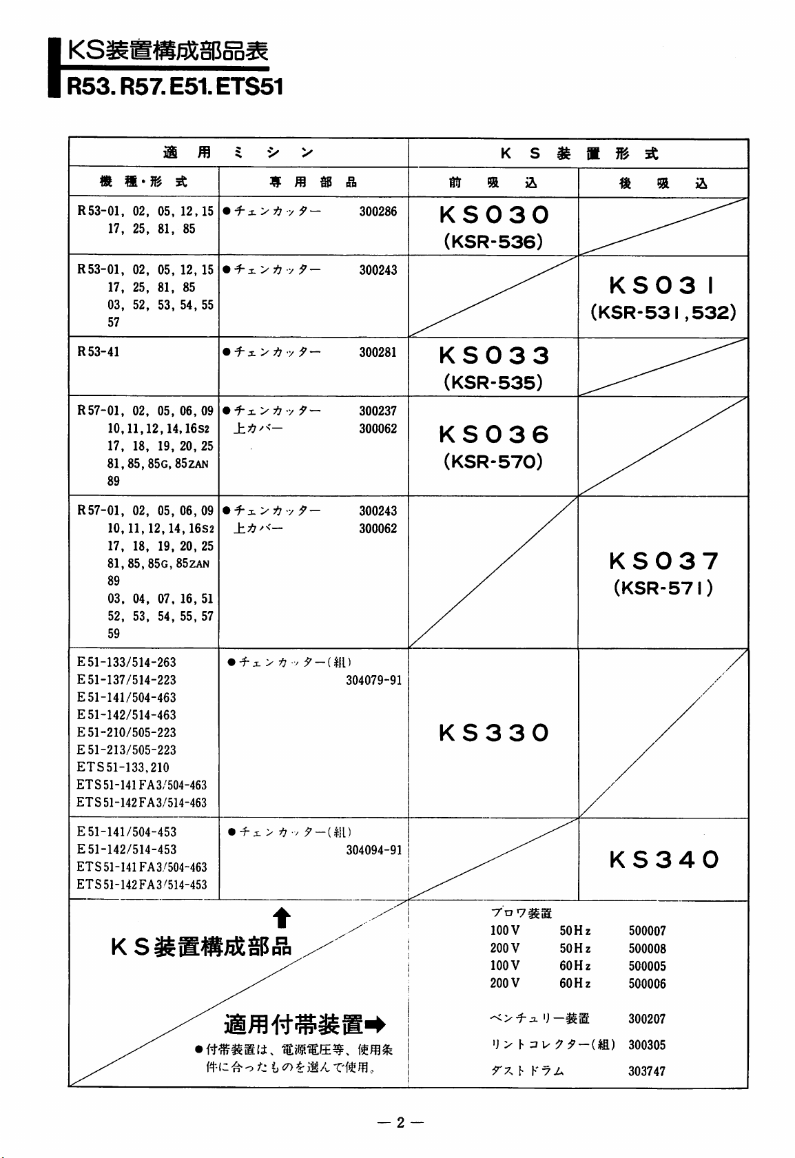
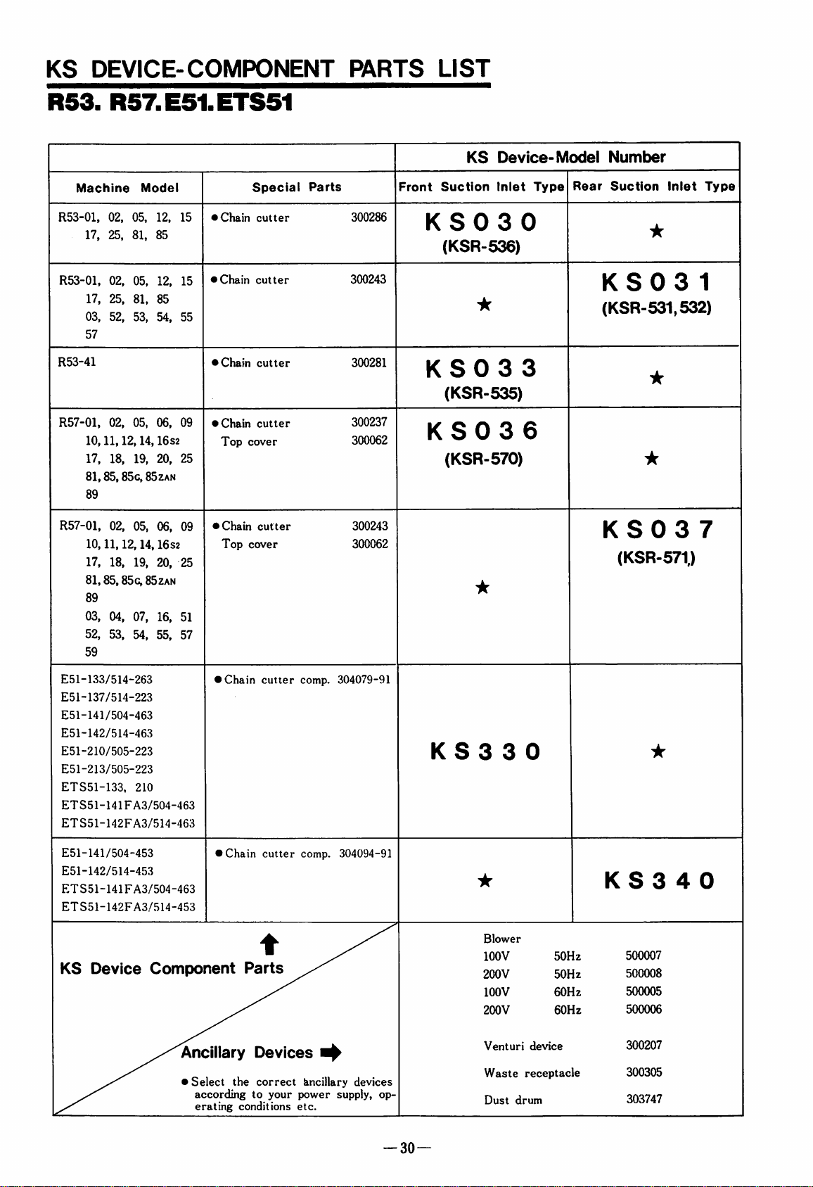
KS^TO^§B§a^
R53.R57.E51.ETS51
m
m
K S
m
M
^
R53-01,
17,
R53-01,
17,
03,
57
R53-41
R57-01,
10,11,12,14,
17,
81,85,
89
R57-01,
10,11,12,14,16S2
17,
81, 85,
89
03,
52, 53,
59
02,
05,
25,
81,
02,
05,
25,
81,
52,
53,
02,
05, 06,
18, 19,
85g,
02,
05, 06,
18,
19,
85g,
04,
07,
54,
12,15
85
12,
85
54,
16s2
20,
85zan
20,
85zan
16.
55,
15
55
09
25
09
25
51
57
■f- i >
"1-
%
^
tI?
•/ ^ —
X. y i] ■ 9
x>
^
xy
i] ' •/ 9
xy
i] ' /•
t(r
300286
%
KS030
%
&
(KSR-536)
—
9
—
300243
300281
KS033
KS03
(KSR-531
I
,532)
(KSR-535)
•
300237
300062
KS036
(KSR-570)
9-
300243
300062
KS037
(KSR-571)
E51-133/514-263
E51-137/514-223
E51-141/504-463
E51-142/514-463
E51-210/505-223
E51-213/505-223
ETS51-133,210
ETS
51-141FA3/504-463
ETS51-142FA3/514-463
E51-141/504-453
E51-142/514-453
ETS
51-141FA3/504-463
ETS51-142FA3/514-453
ft-C
•
-f
•
-f X >
O
X>^
/
9-{m
304079-91
KS330
■/
^-(m)
304094-91
KS340
50 H z
60
Hz
y
\-zjy 9 9-im)
i
^
A
.
9'7^\-V7A
500007
500008
500005
500006
300207
300305
303747
—
2
Page 4
\
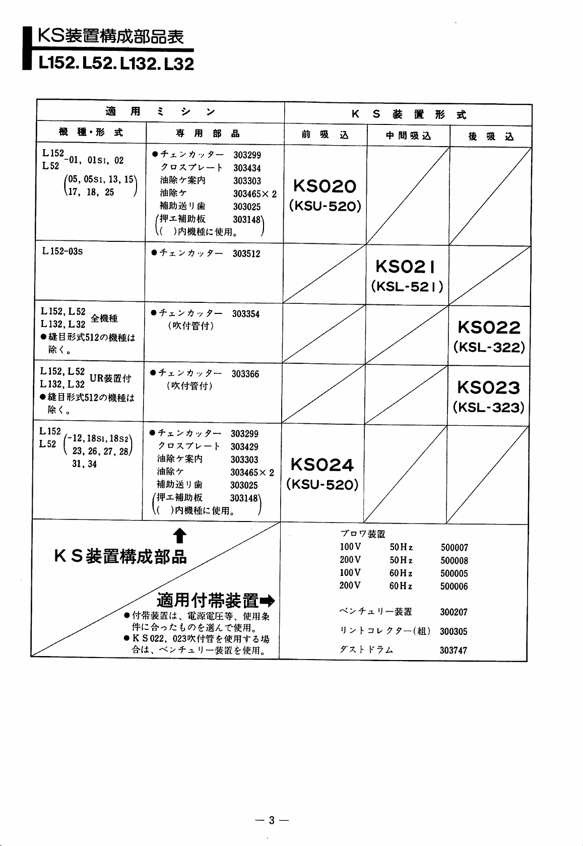
KSi
L152.
L52.
□POD-
L132.
L32
L152
-01,
/05,
\17,
Olsi,
05S1,
18,
L52
L152-03S
L152,L52
L132,L32
•
IISff^^512c7)|^MIi
^<o
L152,L52
L132,L32
il
13,
25
02
15\
^
I
•
:7Dxr^—h
(
•
^:L>:^-y9~
mmm
z.y
V
'j
®
i] - y 9 ~
9-
9 -
303299
303434
303303
303465 X 2
303025
303i48\
j
303512
303354
b5
®
a
KS020
(KSU-520)
K s
KS02I
(KSL-52I)
m
4* ® ®
m M
^
m
&
KS022
(KSL-322)
KS023
i^<o
L152
,
j^g2
/"12,18si,
V
23
31,
,
18si,
, 26,
34
18s2\
18S2^
27,
28)
•
9 3.
KS022,
>
-y 9 —
9 O X7°U—
'J
lif
023^n^^itmir6m
303299
h
303429
303303
303465X
303025
2
303148j
KS024
(KSU-520)
7
lOOV
200V
lOOV
200V
rxhKxA
O
y
}•
Zi]^ 9 9-m)
50Hz
50Hz
60Hz
60Hz
(KSL-323)
500007
500008
500005
500006
300207
300305
303747
3
—
Page 5
\
KSi
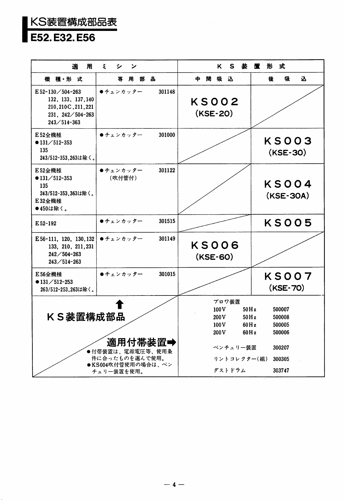
E52.
E
E32.
m
m-m
52-130/504-263
132, 133,
210,210C,211,221
231,
243/514-363
E56
iS
^
137,140
242/504-263
^
^
^
^>-h
m m
-y
9-
&
301148
K
M
KS002
(KSE-20)
s
^
m
M
m
^
m
E52^t^m
•
131/512-353
135
243/512-353,263li^<
E52^mm
•
131/512-353
135
243/512-353,363l±f^<,
E32^^M
•
450(il^<
E52-192
E56-111,
E56^^M
•
131/512-253
263/512-253,263lil^<„
0
120,
133,
210,
242/504-263
243/514-263
130,132
211,231
•
„
•
^:L>ij-y9-
mmit)
•
•
i-j.yi] y 9-
•
t
y 9-
-y
9-
-y
9-
301000
301122
301515
301149
301015
KS006
(KSE-60)
rD7^M
100
200
100
200
V
V
V
V
50
50
60
60
KS003
(KSE-30)
KS004
(KSE-30A)
KS005
KS007
(KSE-70)
Hz
Hz
Hz
Hz
500007
500008
500005
500006
mz^-o
f-o.
fzij
(7)
rime
i) > h
— 4 —
9
9-m)
300207
300305
303747
Page 6
\
KHi
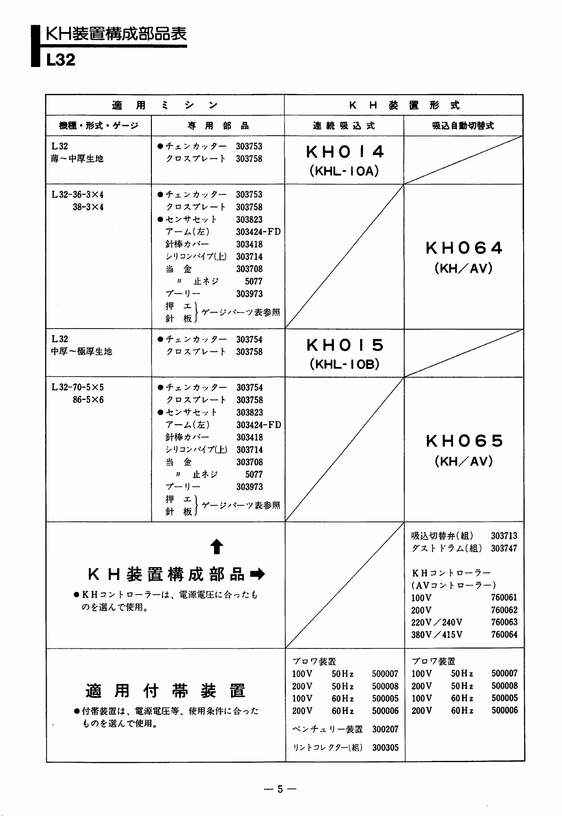
L32
EfiSaBSa;
L32
L
32-36-3X4
38-3X4
L32
m
•
^s-y-h-y^-
^^'Dxr^-h
•
^z.yij-y9-
^axrU'-f
•
-b>-»f-byh
T-A(;fe)
x'j=i>/M7'(±)
i
±
"
y-
'J
-
iffl
x.\
E
•
f-i
>717
;ynxyw-h
m
^
Y— X ^
•/;5'-
303753
303758
303753
303758
303823
303424-FD
303418
303714
303708
5077
303973
-y
303754
303758
3^
US! % ^
KHO
(KHL-1
/
KHO
(KHL-1
K H
1
4
OA)
1
5
OB)
^
g
KH064
(KH/AV)
^
L
32-70-5X5
86-5X6
•
KH3>
m
b
D-7-(i,
m
•
•
^
Ys-yij
;7nxyu-h
-tvy-t/h
T-A(;£)
i+#7t7^<-
1
y-
tt-
^
"
±
'J
-
ji
isj
1
-y}^-
m m
t
303754
303758
303823
303424-FD
303418
303714
303708
5077
/
303973
yoy^B
100
200
100
200
V
V
V
V
50
50
60
60
Hz
Hz
Hz
Hz
500007
500008
500005
500006
KH065
(KH/AV)
yxhKyA(M)
K H =J > h o —y
(AV::J>hn
100V
200V
220V/240
380V/415
yoy^B
100
V
200
V
100
V
200V
V
V
50
50
60
60
—7
Hz
Hz
Hz
Hz
303713
303747
—
—)
760061
760062
760063
760064
500007
500008
500005
500006
'Jvh^uy^y-lliD
— 5 —
300207
300305
Page 7
KHi
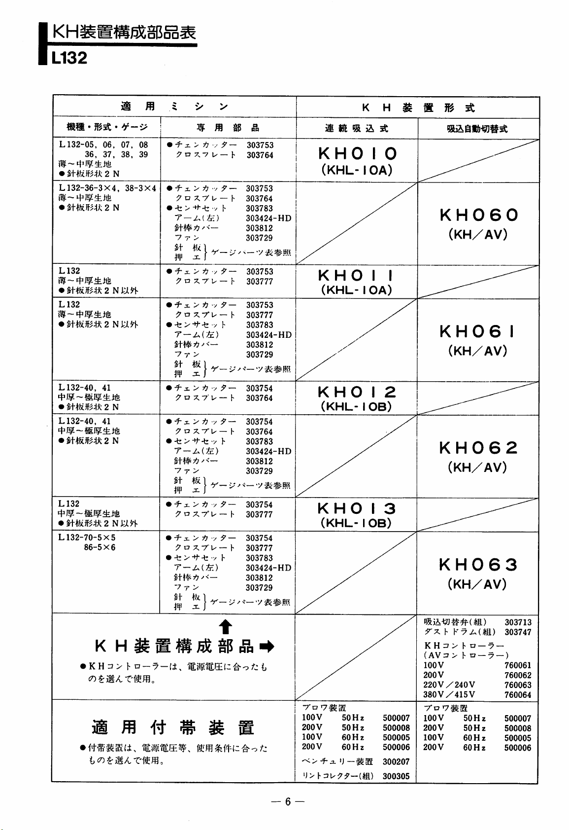
L132
I
L132-05,
•
L132-36-3X4,
•
L132
•
L132
L132-40,
•
L132-40,
•
•
06.
36,
37,
mUB^k 2 N
umm
maifm
%\mm
mmm2
2
2 N laii-
41
2
41
m
• *f—i>
07,
38.
38-3x4
N
N
n
olJoa-
m
^
08
• X > 717 / :? — 303753
39
^ o 7. V u — h
•
-f" X >
77
o X 7' u —
•
-b > -H--b y h
ti-#77-'<—
7 T >
It
t/x
I
•
f-x > 7i7 y rJ'—
a
7, 7 u — h
' -f" X >
'
% & s- > f]
•
7!? ^ —
^ a x-ru
-t
T
—A(&)
st#7:7^<—
■7 r >
It
m
W
-fe > T'-b y h
It
}r-:
^
^7 D X 7 U — h
9o
77U—
V T >
I
•■/
y
/•9 —
r
:?'
—
h
9-
—
hP
—
h
>■' ^
}■
h
ng
303764
303753
303764
303783
303424-HD
303812
303729
<—
-v
303753
303777
303753
303777
303783
303424-HD
303812
303729
303754
303764
303754
303764
303783
303424-HD
303812
303729
K
KHO
(KHL-1
KHO
I
OA)
I
(KHL- I OA)
KHO
I
(KHL- I OB)
H
a
^
0
KH060
(KH/AV)
I
KH06
I
(KH/AV)
2
KH062
(KHy/AV)
L132
•
m}inm2Nk:m
L132-70-5X5
86-5x6
KH7>hn-7-(i,
K
H
m
•
^x>77y;7—
:7 a X
% s- > f] • •/ 9
:7 D X 7 u — h
•
-b > 7
Ittt^7;7''<—
■7 T >
II|tjj
#
jr.
7°
U- — h
-b • •/
I
V—
h
—
303754
303777
303754
303777
303783
303424-HD
303812
303729
•;
a
nn
KHO
(KHL- I OB)
7'D
100
V
200
lOOV
200
i)>}-ziu99-{m
50
V
50
60Hz
V
60
Hz
Hz
Hz
I
3
500007
500008
500005
500006
300207
300305
KH063
(KH/AV)
7xhK7A(M)
K H 7
(AV7
lOOV
200
V
220V/240
380
V/415
7'D
100
V
200
V
100
V
200
V
h D
—7
t o —X
V
V
50
Hz
50
Hz
60
Hz
60
Hz
303713
303747
-)
760061
760062
760063
760064
500007
500008
500005
500006
— 6 —
Page 8
\
KHi
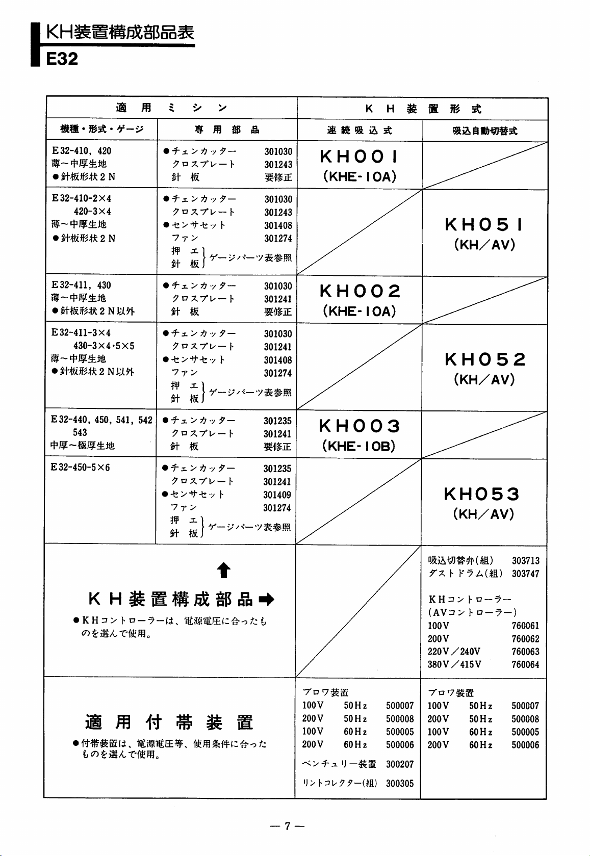
E32
m
WOO-
m
i
^
^
>
^
&
mtim
K
&
A
H
m
s
m
A
E32-410,
•
mRifm2N
E
32-410-2X4
•
E32-411,
E
32-411-3X4
420
420-3X4
2 N
430
430-3X4-5x5
•ii-mmu2Ni;in'
E
32-440,
543
450,
541,
•
•
•
•
•
•
542
mi-j.>/j y 9
n
-y
f-
;;^oX7°U—b
It
m
y 9-
^u7.-rv-\
-b>^t-byb
7 T >
W
JZ
]
i-j.>ij-y 9 -
n-
M
&z.>tiy
^nx7°u-h
-fe>-t-b y h
7 T >
7nxrw-h
9-
-
wi
301030
301243
mm
301030
301243
301408
301274
301030
301241
301030
301241
301408
301274
301235
301241
mBiE
KHOO
(KHE-1
KH002
(KHE-1
KH003
(KHE-1
OA)
OA)
OB)
1
KH05
1
(KH/AV)
KH052
(KH/AV)
E
32-450-5X6
• K H 3 > h n
cr>i:m^X'imo
3®
—7
•
i-:L>i]y9
•
-by-^-tz-y
7 T >
—
TO ^
t
h
-
B
301235
301241
301409
301274
/"j
t
7*0
100
200
100
200
V
V
V
V
7^®
50
50
60
60
Hz
Hz
Hz
Hz
500007
500008
500005
500006
KH053
(KH/AV)
rxhKxA(M)
KH=»> h o-x-
(AV:3>
lOOV
200V
220V/240V
380
7*0
100
200
100
200
V/415
7^®
V
V
V
V
1«o
V
50
Hz
50
Hz
60
Hz
60
Hz
—X
303713
303747
—)
760061
760062
760063
760064
500007
500008
500005
500006
')-^m
'l>h^i^9f-m)
7
—
300207
300305
Page 9
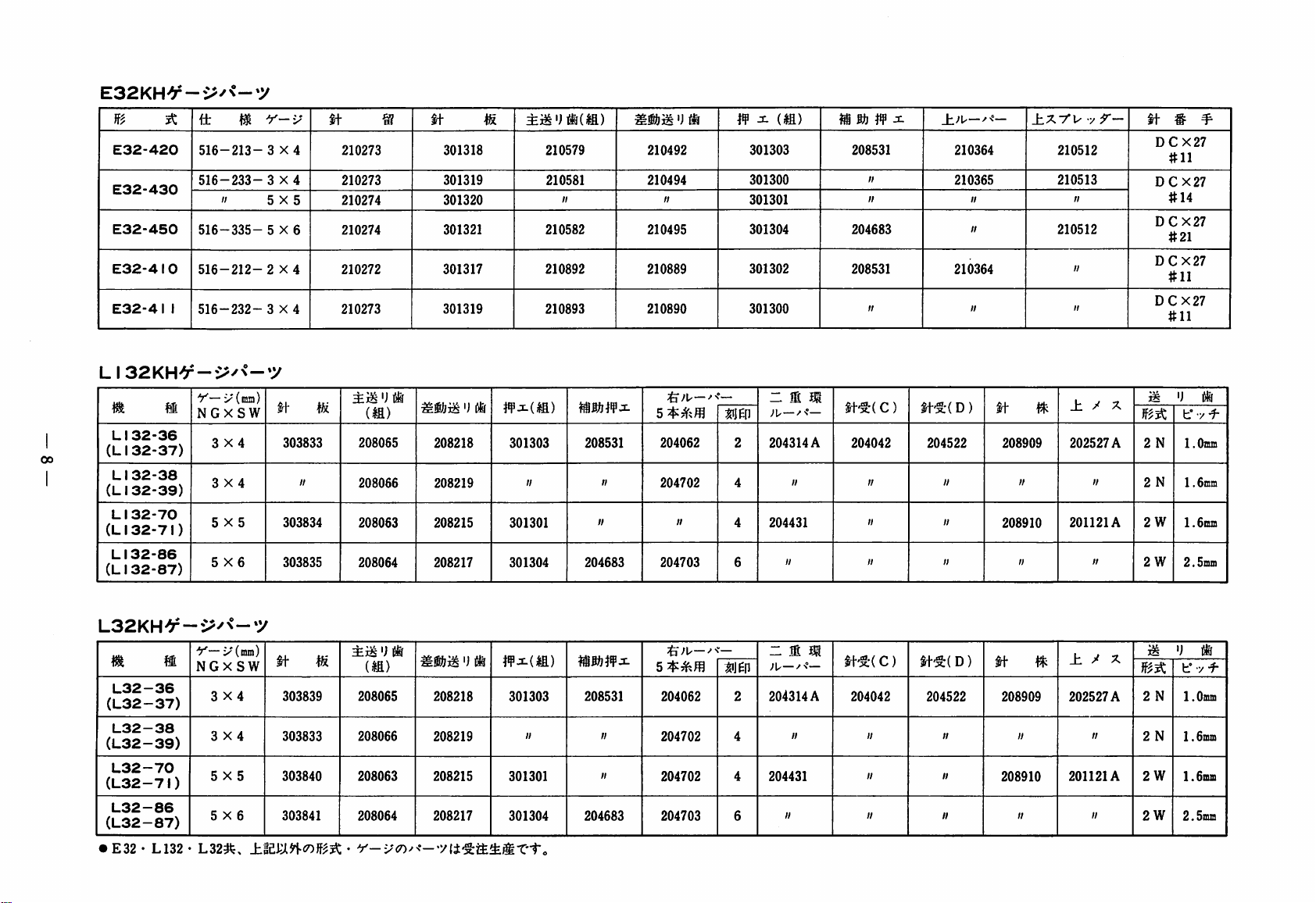
E32KH¥-i>^<-y
}f^
E32-420
E32-430
E32-450
E32-410
E32-4I
^
it
516-213-
516-233- 3 X4
516-335- 5 X6
516-212-2
1
516-232- 3 X4
m
II
LI32KH>5r-v^^<-»y
Y—
NGX
5X5
5X6
i'(ma)
SW
3X4
3X4
LI
(LI
LI
(LI
L1
(LI
LI
(LI
W.
32-36
32-37)
32-38
32-39)
32-70
32-71)
32-86
32-87)
y-i^'
3X4
5X5
X4
ft
303833
303834
303835
ft
ifi
II
210273
210273
210274
210274
210272
210273
(M)
208065
208066
208063
208064
®
')
(if
ft
msm
208218
208219
208215
208217
301318
301319
301320
301321
301317
301319
>)
^
(if
301303
II
301301
301304
210579
210581
II II
210582
210892
210893
208531
II
II
204683
210492
210494
210495
210889
210890
^
204062
204702
204703
U
JU—
II
M
ff (la)
301303
301300
301301
301304
301302
301300
•—
nw
2
4
4
6
~ m m
-'L—-'n"—
204314
II
204431
II
A
208531
II
II
204683
208531
II
ft-SrC
C)
204042
II
II
II II
±;u—
210364
210365
II
II
210364
II
ft-SrC
D)
204522
II II II
II
ft
208909
208910
±XYUyr-
^
II
210512
210513
II
210512
II
II
± / X
202527 A2
201121A
II
ft
ii
2
2
2
#
DCX27
#11
DCX27
#14
DCX27
#21
DCX27
#11
DCX27
#11
N
N
W
W
^
u (if
b° • Y
1
.Omm
1.6mm
1.6mm
2.5mm
L32KH^-v>^<-»y
TO
®
L32-36
(L32-37)
L32-38
(L32-39)
L32-70
(L32-7I)
L32-86
(L32-87)
•
E32 • L132 • L32^,
Y— X (mm)
NGXSW
3X4
3X4
5X5
5X6
ft
303839
303833
303840
303841
ili
'J
jSfe
(M)
208065
208066
208063
208064
•
Y-i^<n^<-'yli-^m^mX'tc
Mmm')
208218
208219
208215
208217
wMm
(s
301303
II
301301
301304 204683 204703
208531
II
II
;&;u—>->
204062
204702
204702
2
4
4
6
~ M m
;u——
204314
II
204431
II
A
ft'S;(C)
204042
II
II
II
ft'§:(D)
ft
204522 208909
II
II
II II
208910
_h X X
^
202527
II
II
201121A
II
ii
t° • ■/ Y
2
N
1
A
2
2
2W
.Omm
N
1.6mm
W
1.6mffl
2.
5mm
Page 10
R57
I
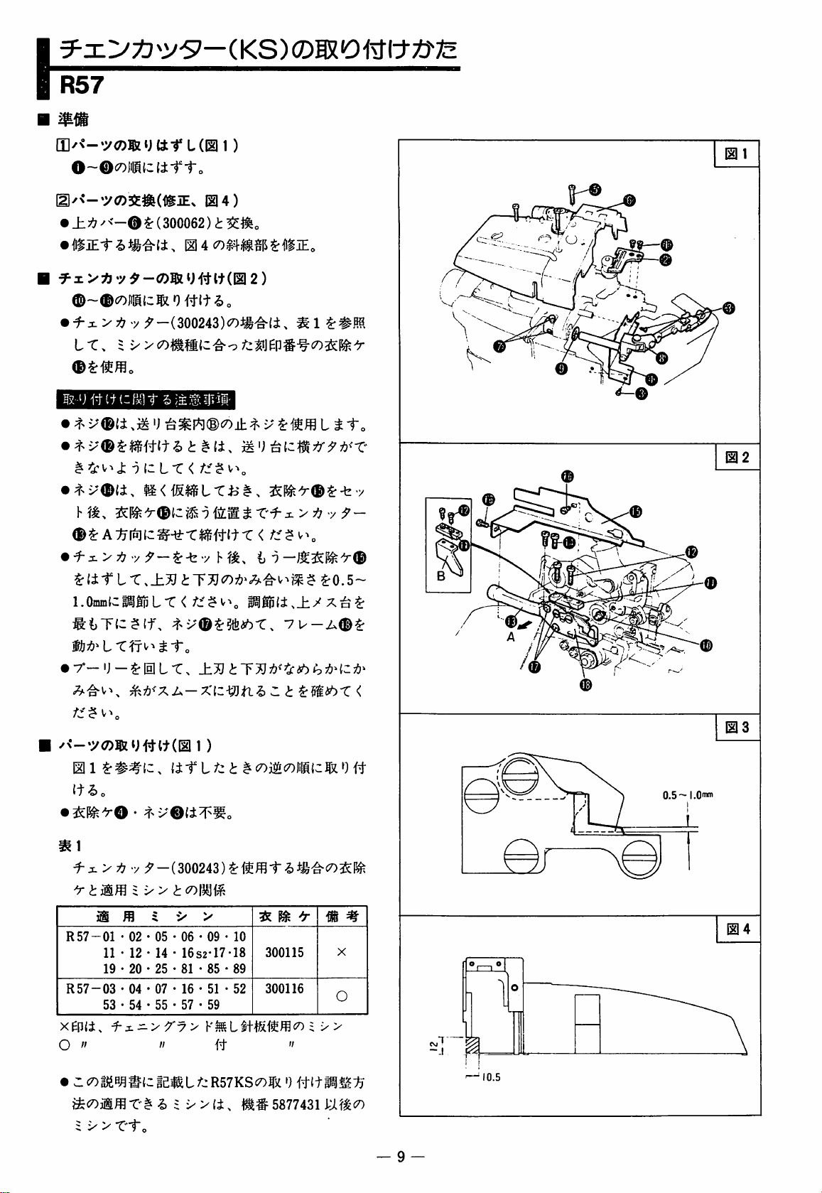
(I]/<-.y<7)|SzytttL(Ell )
o~0<7)jnMtc(±-rto
(2l/<-'y<7>SE#^(1lfiEx
•
}Lti^
<-0
i:
(300062
5^1
•
i-:^yp^
-y
yf-(300243)com^li,
LT. ^ >'
ycoi
04)
I
•
^
0^At\tniz^-±XmWX
^ittix
i.o!mizmmLx<f^^^\
'j
J; 9 (2
.±j}
LT < /".:'$
v-»„
2
)
mii:0m
itto
<
^0.5-
i^gp(i.±yx^^
%
02
^<—^y<7>®zu#tt(0
m
1
It^O
mi
^ X >
R57-01 • 02 • 05 • 06 • 09 • 10
R57-03 • 04 • 07 • 16 • 51 • 52
xep{±,
O
•
Ccotfi5B^#{;He«cL/>;R57KSco43i
717
-y y -
11 • 12 • 14 • 16S2-17-18
19 • 20 • 25 • 81 • 85 • 89
53 • 54 • 55 • 57 • 59
f-x->7'7>
"
i X >
Xto
1)
.
(if L /:; t ^
(300243) ^ ffl 1"
"
i> $ xXi,
ft
It#
(Xi^cowmzm
m ^ ^
300115
300116
5877431
-i)
"
P
0
m m
X
O
X>
1^^7)
—
0.5-
I.Own
CS.T
-.1
10.5
9
Page 11
\
R53
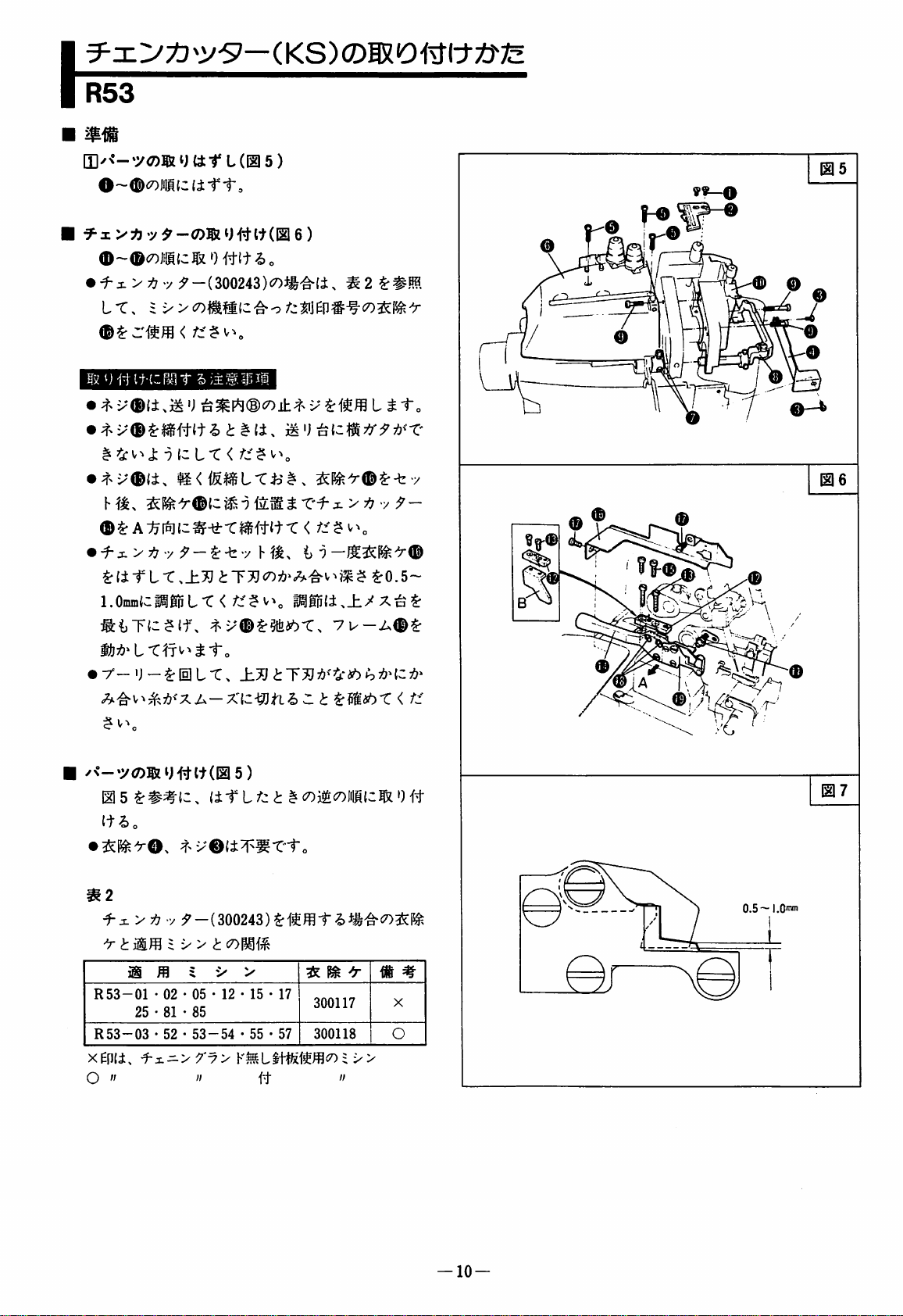
|I|/<--yOT®iJttt
VA
y^-ro®iJ#lt(E16)
0~®i7)»S(cR')Wt?)„
•
^x>7>
i>;u^4if{cr*Tr
^
•
f-x>7:7
yy-(300243)<0»-g-li,
5>)3Esrii
J: 9 {3
ft < /■>; ? ^'■'o
-y
^li-rL-t,±^^T^c7)7!7»;^'^v^?f
l.OmmtcMgRft
<
L(EI5)
i
>7:7
Plp{i.±7'X^^
7u-A<D^
$
V
i^0.5~
ff
@5
f—O
o
@6
•
r-ij-^dlft.
Ill5^##(c.
(i-rLZ-ci
tt^o
^2
•X
<J:
R53-01 • 02 • 05 • 12 • 15 • 17
R53-03 • 52 • 53-54
xenii,
O
"
i X >
iS
25 • 81 • 85
•^x.=-yXy>
i:
5
V
>
•55-57
"
ft
i
^mubX < Z-^'
^<7)il&X>IilH{3^0#
^
^
m
300117
300118
=
"
X
0
x>
©
07
4—
#
—
10
—
Page 12
L152.
L52,
L132.
L32
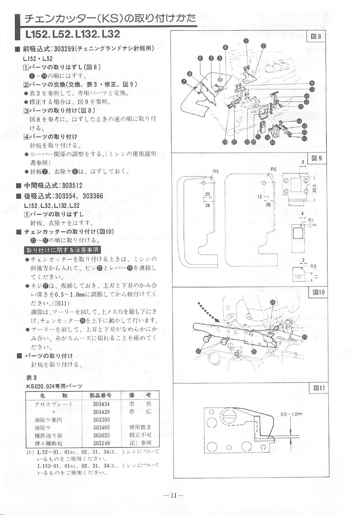
^5aiiit:303299(^x:i>^'-7VK:#-xtt4Sffl)
L152 • L52
[I]/<-'yc7)ga u itt L (0
!2l'<-'y<7)^fi|(5#6.
[gy<-.y(7)5[iH^W(EI8)
ms
(t^o
[iT
i-„
^3
8)
1*19)
<7)1^collateSio#
•
*#.Ha.)
•
mm.
tm'roit.
=t=rBmi^^:303512
303354,
L152,L52,LI32,L32
[]]/<--y(7)
X > ^'y
©-©conicfx')
•
i-^>y7-y
X
<
iJlit'L
^
la
^
0.5~
1.
OmmlC
>
yj
■y:$'-®^±.rizmy)'ix'ii^'tt,
in'imi.
303366
(J # 11C^
Hgp
n^xyyitm-mn
10)
L-C
^
li^xyy
T
<
KS020,0241Fffl^<-*y
iJ
B
i£)
L52-01.
L152-01.
OlsK
Olsj.
ijcn^zsi^m
Sgg°pS-^
303434
303429
303303
303465
303025
303148
02.
31.
02. 31.
<
34(i.
34ii..
t^^ebX
B #
r1i
rti
m
ii^XlOv^-C
iv>;zov>-t
mx
<
ft
O
O
-
o
o
j
I L__
'o
Page 13
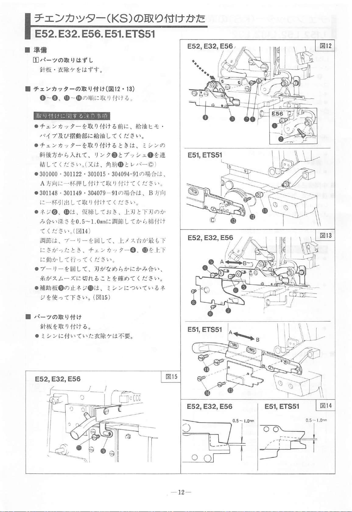
E52.E32.E56.E51.ETS51
mm
[]]/<-'y<7)®:UU:-r
^:L>i3'y9-<7>JSLi)iit.imn • 13)
O-®.
•
301000 • 301122 • 301015 • 304094-91c^^^^^^ti.
A
•
301148 ■ 301149 ■ 304079-91(/>^^-'^f±,
iz
•
t>i-'0,
T < /^■?v^,(E]14)
mmt,
iz
^zmt^lX'ii;nX<
®~®<7)iiiii(c^zgfW^.
fi
-4T4¥ L ftt t T
1
tti L xm 0 iwx
®li,
^0.5~1.0mm(3i^§RL'C7:)'i^l?i5-#ft
r-O-^IULT,
tz t ^ . ■i':i. > ij
L
L
-r < fJf
'J >':?®t7*vxi0^ii
'Ht(t T <
«LTiJ^,
±/
■•/
f—Q s ®^_hT
?
u•-<-©)
/f ^ ^
B:^l^i]
±J}tyj)cO:^^
E52,
E32,
**11
E56
7^^=f:
^.ib^'X2.-X^z-^tl^Zt
•
fflfifi
^®c7)iL^
/<—•y(7)B2t)44-l+
x®(±.
(iai5)
^msbX<
=
E52, E32,
E56
0.5—
I.Omti
Page 14

L132.
t
L32
016
(D/<--y«)®
ij
(it
^ n XT'u—
•
<Z)5ZU
•
f-i>y7v
xri^-h
Sr-k-y
^ D X7"u- h 5.
h^X < /i$v^(018)
L
h
016$:#Mo
^x-rv
^4
h
^Utto
-i^jEx
016)
'y t ^jl^o
#1^(017)
i
t^xO$:5fei6-Ci^lnt
(h
C7)P^
$:^^J0.
i7D
4minC
2.5-^^-
I
R5
,<~r"
12.6 n I
T 4 ^
34
I
b-
20
Rl
-75.3
~~r~
23.5
J_
.45*
017
')
t0.5inm±(C^>{fT<
^
^i^^0.3nim{cMLT < /j:-^«.^(02O)
36»
LT^f o X
•
r-U-^lULT,
^.:f3'XJ.-XlZ-^g}tllZt
m4
iS
ffl $
m.
m
L132
L132
L32
2
2
3
3W
2N~3W
<
>
N
W
N
/
1®
/ ^
(D
1 (
^mibX
Di^PfJ-#"^
303764
303777
303758
'
o,
1
7
(A
|>
<
018
#
m
016
016
016
020
0.4nvn
019
[—G.3mm
—
13-
Page 15

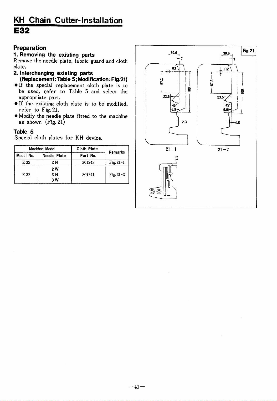
E32
(if
L
Itts • ^^.^]kl/9^x-rv-
h
^(i-ri".
30.6
30.6
11121
,
7
• ^ a
•
X7V—
h
(l|jE-r-2>^i^(i,
iS
5
->
>
wt
m
E32
E32
2
3
3W
2
N
W
N
^5
12121
-y
t
301243
301241
—
12121)
h
#
m
12121-1
12121-2
.t
23.5
21-1
R2
. J
45^
6.9r;
1l
-2.3
U7
J_.
23.5
21-2
c
R2
I
45*
6.9'-
7
J
-4.5
-14
—
Page 16
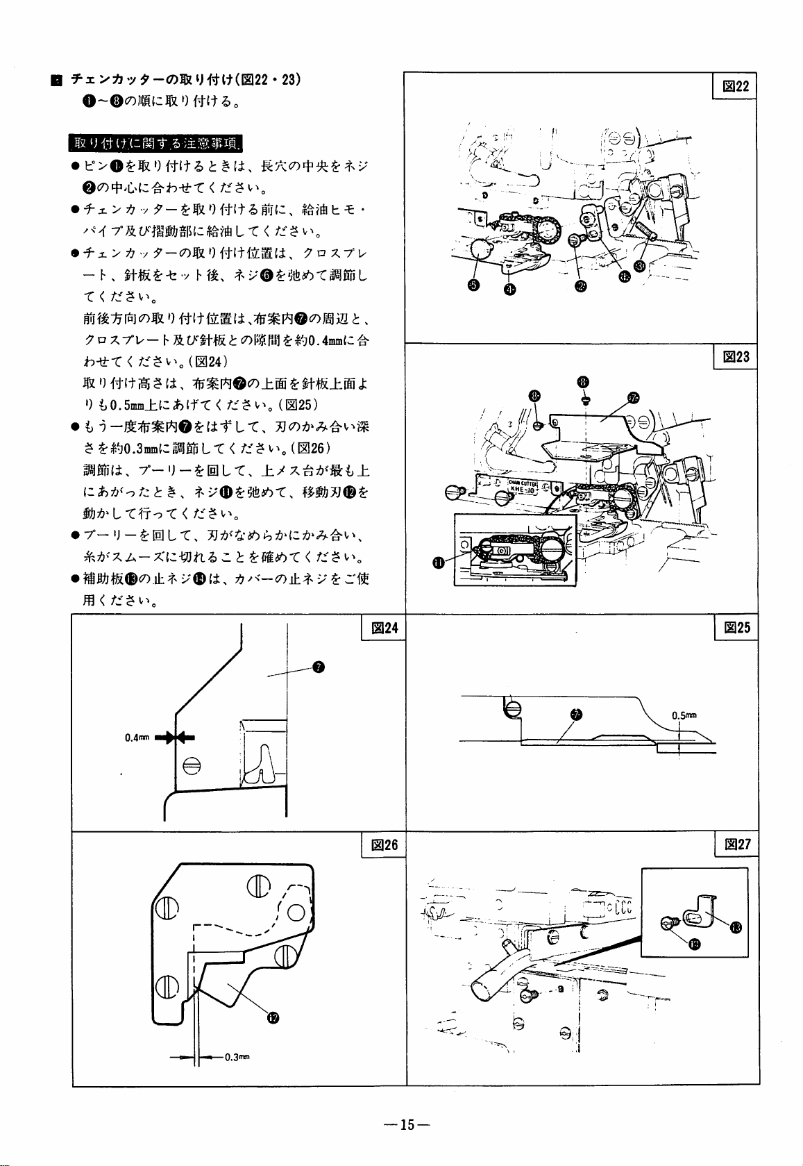
naiEiBBraEii
•
0c7)4i>i:^(C'^b-^r < f::^^\
•
f-x > 7!7 V :?'
-C<
0 #tt
—c7)^»)
l> i ^
®
1122
o
^oX7°U—hS.
ib-ti-r
')
$
i^gfili,
<
^0.5mm±{C#)lfr < fz^^\
^|J^0.3min{c|^gnL-C < /::$
r-g-^ElL-C.
(/§ttS i <7)
(1224)
{zhi3<-otzt^.
Myf?' L T^to T <
•
<7).ill
0.4f^
X®
(i,
li^
fjg ^ I^jO . 4mni{3
(1125)
i]^<—
(1126)
Z'^
@24
^ttlTTU)
@25
@26
O.Snw
—
15
—
@27
Page 17
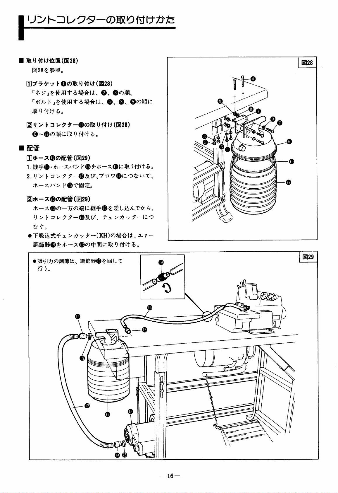
\
E128^#Mo
{y\y
^^ y hO<7)®U#lt(12128)
■"'-K^uh
^')fW-2>o
mi; > h □ u^^-®<7)®iy#it(028)
©-©council
(I]?f.-X®(7)E^(|2129)
2. U > h r? u ^
.tx
—X^<>
m?^-:^©<^E®(029)
rf
-x — X
©CO—
ij > h
r? U ;J'-©S.O\
4-<'o
•
P»©^d-^-X©cotr^tc^»){W^o
0#(t-2)0
K©^:'^'^—x©{clx')#lt^o
©^lO\7'o
K®T'gl^o
> 7
-y
f-i
;?'-(KH)co^i'^(i,
©>
®,
7©(20^v^t:\
^
t
>7-y
©colic
:f-{30
J^r-
b
©
s
WMij
©
© ©
—
16
—
Page 18
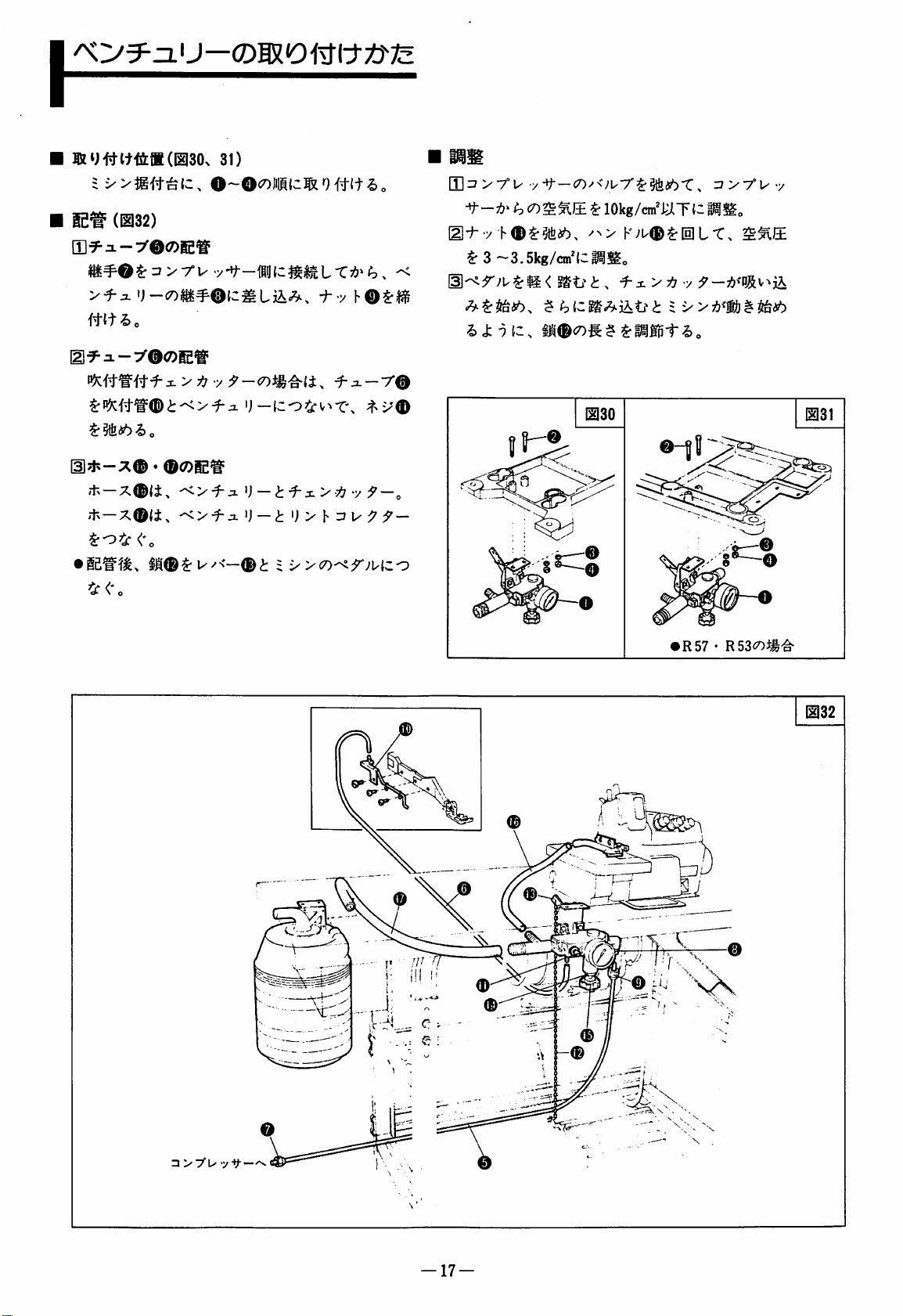
\
ix>$g#^{c.
|£^
(11132)
[I]f^3.-:/©<7)ie^
31)
O~©<7)Jii(c^0#it^o
[Hz/>7°U
-t-Ti/'
^3~3.5kg/cin'(Ci^^|,
y-t
—C7)y<yU7'$:§tfei6t:,
<7)^^|± ^ 10kg/cm^l.JlT{:il^!^o
Ziy-fUy
^
mi>o
[iif=-i-y®<7)ie^i=
y
o
(l?^-:^© • ©(7)iei=
'+^
—X©|i^
itx—X©(±,
^o=S:<%
•
^<-0
^>-i-SL
-O-f-jL
i-'y
f-i-r©
^) — ti-:SL>'
'j
—i";>huu:7
= x>c7)-<r>'Hco
tf
"/
f—o
f
—
R57 • RSSWl-g-
^32
©
—
17
—
©
©
Page 19

tzytf-tz^y
L132
I
[I]y<-y<7)|SHj
(i t L
0-ii>cr>miziitto
• T - A (&)
[l/x--»y<7)5iU4tlt
033^
^0
#Mo
me
KH060~063li:ffl^<-'y
r-M^)
7 T >
It
If
i
##(c
{2
ft ^ r V >
(i t L
(033)
0 6 •
I, p gR X #
i ^ <y)i^colUMJc
303424-HD
303812-HD
303729
■(gJEx
034)
CO ^ N-- • y
m
034-l#.fKi
034-2#.»«
fl^iE^"T
n
II
0^e
®
0
')
#tt
0
0®
#
-
43.7
-J
—
18
Page 20

(11135)
n]^m(7)W^Vt^^^^2Nj(D i '>>(L132-36 • 38«07-
39^)
7.-<-^-O^CP't>^Oty'y'r'y
b®c7)
11135
(E)
x-^--
d
h
86,
7'7^-x
>
88^)
LTl^S $ vV(L132-
yy'r y h®x>g5\(i)^Mo-t:.
[lCP'b>-»f<7)=f-K(i.
v®T"4
^36^##(c^u
ij?f\^±.sbh.
rx^-y f $•
v
7°
O
0
0
11137
[I]/<-«y(7)lttj(i-f
0~®o)iIM{z(i-f
l(®37)
i-„
[2l/<-»y<7)5tS&(^6)
7 T >®
[I]^<-*y(7)5zij'ftlt(I1137)
ma?
(t^o
•
'j-(Cr[D]
•
Z3-
^##(3,
K{i.-< y K-^§>i^gfeliL4-v^J:
lj
Ji-
(itLtii
t
It
t
(11137)
^xxmn
^Oi^coJilMic^'ift
-)
(c
#(t
!>
y-
ihy)^..
»?
„
—
19
Page 21

\
L32
[D/N--'y<7)5iij
•
T-a(;£),
•
T—A
l3l^<-»y<?)®iU#It
mas • 39^##{c(itLtc
(it L (EI38 • 39)
th#7:7^<-(i.!2l4060ii0{c>fliiEo
(;£) H oi
^-C V ^ ^ Pin
m7
-^je.
'y(i,
(11138 • 39)
t |i<7)i|frc7)jiiK{c^>)
;f.
#{tl>o
• ^ X > y? y -
(KH)
')
#{t
Mo
CP-b>'-9-<7)5iiJ#lt(I1141)
[1141^##{C
m h 7 ^ ^
-ff
i
X
L T Ll- ^ >'(L32-86,
88^)
iii4o)
X
iV'Xcov"'
t:
7'y^-yh^
{i.
-y
($),
13M
0
o
\i:5,
^
0
1
ryy-y
S^¥HU{3?iaiLT^0#lt-2)o
CP-fe>-'t<7)n-h'®(i,
•r®^lt/^^x®T'4
Kw * 9.b
/ 4.5
40-2
ijfh^itubho
^
>r
'•
\
y'y'T'y h ^
I2|42$:##C
-43.7-
-44.2-
y'j
y
KH064 • G653§:ffl/<-'y
m
#
r-A(^£)
f>
1)
=?
h 7 y
•/_
i;_
if
tf
i
>^<^
ts
7(±)
303424-FD
303418
303714
303708
5077
303973
I1140-1#8S
i2]40-2#ra
dlJE^'ai
II
II
II
II
II
—
20
Page 22

[T]yN'-y<7)5iij
(i-f
L(043)
0~©<7)|iiI{c(iT-to
|2]/<-»y(Z)3^SI(a7)
r-
u
^y<-yoj^
043
'J-tCigij
i)
It
(043)
0te«^m«<7>5iiJ#lt(044)
1.7°-
'J-{C'<;uh
2.043|:#MLT.
•
-<;uh
717'-K=^^')#{t-Cv^'g>
IIl®I*l#lttS[g(045,46)
045^##{3^^ai^affi^7°-
(cr&jtt
1.
OmmtC
T. a ®
i:
-2)
7°-
o
<7)ii&c7)iii
'J
-iSUffi
t
{c
m.
►)
m
i
o
=
,
O
^
'j—<7)4i>i:>:^f^
^0.5~
044
V
045
•
7-K7!?^'7°-g-^t^ML^v^J:7(c,
h
®C7)J; 7 {cjhi6l>o
KT\
7>
046
046
—
21
Page 23

I
E32
CP-b
047^##{c
fZ^tho
[EE32-430,
X^-'^r-O^'Ty'r
[11E32-430,
U
=
440
1175-2^^^fflo
AA0Ul9\-<Dii^>
@{i.
1202$ri^fflo
•
7°®^tr/'^^
v®-C'3
K®(±,
7!7P;fl:±i6-2>o
Iil^^a3SS(7)liiU#lt
(047,48)
-/
h®^
=x><7)r^{c|i
|2]48^##{Ci7 U -y
1
047
E32-430«440
ftl
[E^<-'y0®iUtt-r
7
T
L(049)
04£^aiSS®<7)®l U 4^
049^##{c^»HW-g>o
•
3—K(i.
<7)51
049^##{3,
{t^o
'j
-©{cruj
^8
KH
7t>
It
ijftlt
IK
h
(049)
\.i'fLfzt^<r>m<r>]mzW)ii
ij
✓\ — *y
t
It
(049)
301274
9{3±i6-5)o
m #
//
II
049
L
. ,1
®
22
—
Page 24

[E-f
>7"^
C P -fe
L ^ 1".
yr>cr>-7r^^
-(INDICATOR)
{CLOTH
C P -fe > -'t
-(COUNTER)
-y
^
m\ L ^
h
1"=
DETECT
^
igSfr L -C V ^
ON)
^
iNOICATOft
o
e
[4]MIBSi5(SEN
C
P-fe
>
ADS)
[lJiv.^tei6(START)
^
•^—Iz^?: U ^
to
(FINISH)
wmcomm^
-i-7—
^
ti
ymcnmnz^W61
L
^to
•y^(POWER)
=7 > h n —7
(Sl/^-f
O'y h 5
'Mx>f
—(7)'^il?;x
vt^^oNj
KH 3 > h □-7-<7)®I
r — 7'; u c?)
•
KHr>>
;£
101T ® U © ~
h
o-7-ii.
^ L i
to
,
'f
v-f-f'to
tJ-ft
tt
(EI51)
®
I'iC 'J
'til"r€f±l3i^:-l:/j^jc7)
w
.^.^TL^t<
It t §
<
PEGASUS.
^<5^0
POWER
« M
o
tt(Ill52)
Page 25

3-
(IIB®a-K
0(7)3-KS:a?©-0-©<7)1^.
i.
(053,54)
— 9 —
c7)X'f
053
(£t.o
x^tC)^^LT
054
0+aia-
t«83-K©-©.©?:««1-2,t#l±,
Tr - r
K
(055)
3
(f. 7 ^' - m&t
ft
®(7)h-—
^i-Tffl'TOig S 4-(3:a U jt)')
i
o
Kat/'XT-r)U
?)
o
|B|6,
055
□
24
Page 26

\
(12156)
mmm<^xom'^ ^ i^ t iiAMtc
t^C^LX<
i^ox-m.
►)
#it
dl/l-^-xO • 0 • @<^121=
l.li^©
^h\
2.056^##lc^/t>
KOt'gj^l-'&o
•
;tN-xO(i.
•
.t^-X^<>
'PLMiblzLXh*)
K®i^7n-Xc7)i^i!^(c^L
—X^o^v^Tx
(056)
<
/w$
tto
v-»„
d-x—X^<>
^tc<:
^7. h K7A©(7)Jgf^ita
T-7';uc7)^tIij{z®
•
D-&?l:^X)|^|pli,
ff
•)
o
i^lflS5©^IilL-C
<
„
(056)
mt>-700^m
l.;^-x0X)ii^^i
2..tv-X©cO:rx
^T':^X
i > t!/ y rJ'—
•
(056)
h
KxAfilJlw,
h
K-7A©{co^v»t:x
i I'li.
<'o
ni^ixp®tc^^.yr
xr-liln
;?-{C:rx
h
056
4
0
®
—
25
—
Page 27

tz
ytt-tz h (Dm^
LI32«L32(E!57,58
^57-58^##(c,
miri>.
£32(058,59
(USB
-
L32
-^9)
-559)
fxMmznti>±ncon^^
^9(7)=^li5^)!iCt^£oTl^
■/-IJ--(7)-7/;^-y
h
t
I
y > xm^'An-r
L132-E32
=
y
hzt
i>zt
^mmt
7r
^mutho
^PEGASUS.
h.
y h t
[a
POWER
n
Page 28
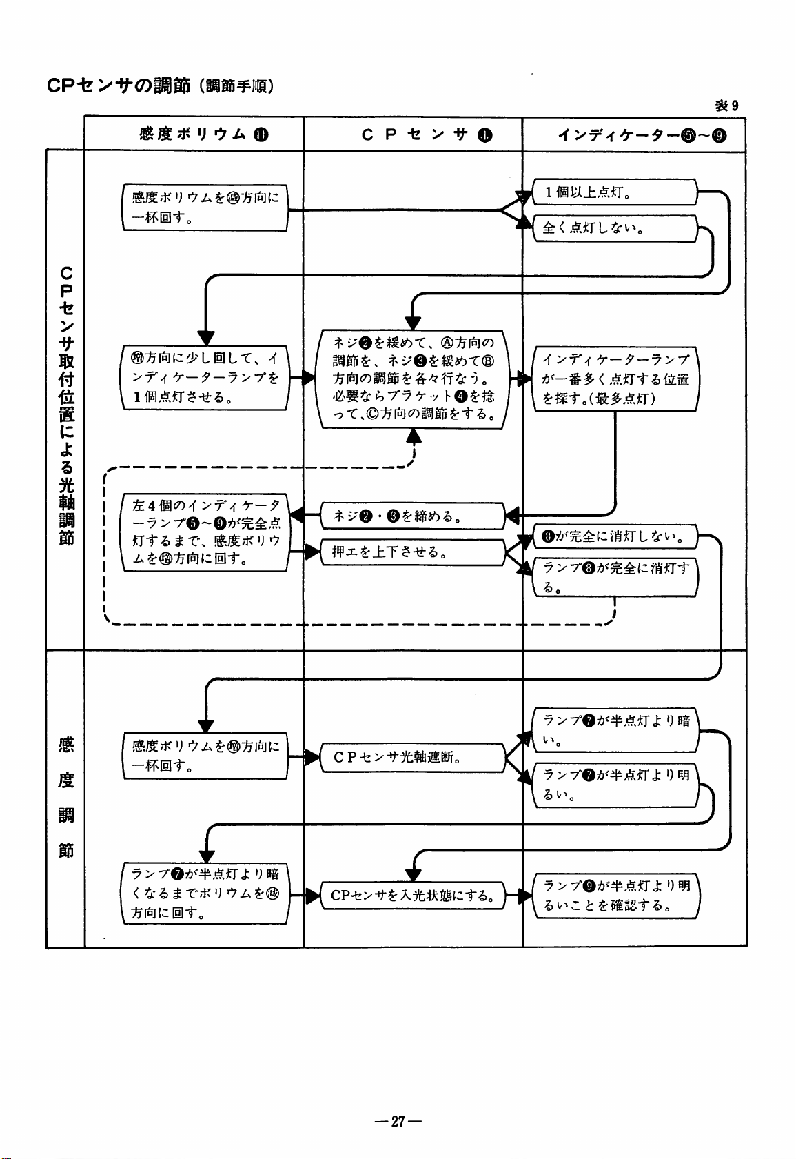
CP-fe
vy-oisas
(Ki5¥ll)
09
c
p
•fe
>
it
s
(C
J:
%
3fe
-fmto
>T'^
I
U A
f—9
>f'>f
®
C P -k > -If
O
1
mj;Ji±mr.
<
f
I
®:^f6]c7)
\
^
>f'^
^mtoiMi^An)
'y—
Ant
^—y
yy
i>iiLm
15
Jt
15
T\
M;KU
/^tr®":^f6j{wIili-„
i
—^=T^Ia]1"o
I
yyyO^^'tAM^
:^i^{clil-t-o
•)
Bg
CP-t>^t:)fcM0i/To
•7 > 7°@;&^'^^(zf^''j:Tt*
t(
I
yytO^'tAn^
i>
v-»o
7>r©;{?>#.^,iTJ:
H{
t
^mut6o
')
»)
—
27
—
Page 29

KHD>sn—
cz)i®i
ai.^t&i(C>^-f
v-ocmeo)
«t^ii?»j^'-fv-@(ia6o)
0
[z-®^c7>PJiix^7&>
•-^ # ;c V ^
V ^ j
miOIRlNJzODjil
1.K H ::? > h n —7
—i±.
1^3 ^ 7:^<7)P^i\At;
-V
[H
i-,
i
(7)
2.KH
3.KH3>
4. C P-fe>t(7)U > X®^^t>\
=» > h
n-7-[±,
I-#-
X
<
h
a-7-(i.^^U^v>-r-<
:^-i&itL/-^i^{±,
-nmm.
AfL-r.
^mtfztt
IC-
hyyyx^-^j:
nrv^ ^ to
i-3-y
^ts_hffi'75^|t®
CP-t>tt7)^#^
l
t-v^r- < z-:r^
igtt.
ttzu^^
ito
Uti.
Page 30

KS
Device-Component
KH
Device-Component
CONTENTS
Parts
Parts
List
R53
L52
E52
List
L32
R57
L32
E32
E51
E56
ETS51
30
31
32
33
Gauge
KS
KH
Installing
Installing
CP
KH
Installing
Checking
Adjusting
Parts
Chain
Chain
Sensor
Controller-Installation
for
E32
Cutter-Installation
Cutter-Installation
The
Waste
The
Venturi
Set-Installation
The
Dust
And
Adjusting
The
KH
KH
and
L32
R57
R53
L52 L32
E52
L32
E32
Receptacle
Device
L32
E32
Drum
The
Sensor
Controller
E32
KH
E32
E56
Set
Machines
E51
ETS51
34
35
36
37
38
39
40
41
43
44
45
47
48
50
51
53
Precautions
53
—
29
Page 31
KS
DEVICE-COMPONENT
PARTS
LIST
R53.
Machine
R53-01,
17,
R53-01,
17,
03,
57
R53-41
R57-01,
10,11,12,14,
17,
81,85,
89
R57.E51.ETS51
Model
02,
05,
12,
15
•
Chain
25,
81,
85
•
02,
05,
12,
25,
81,
85
52, 53, 54,
02,
05,
06,
16s2
18,
19,
20,
85g,
85zan
15
55
09
25
Chain
•
Chain
•
Chain
Top
Special
cutter
cutter
cutter
cutter
cover
Parts
300286
300243
300281
300237
300062
Front
KS030
KS033
KS036
KS
Device-Model
Suction
Inlet
(KSR-536)
*
(KSR-535)
(KSR-570)
Type
Number
Rear
Suction
★
KS03
(KSR-531,532)
★
★
Inlet
1
Type
R57-01,
E51-133/514-263
E51-137/514-223
E51-141/504-463
E51-142/514-463
E51-210/505-223
E51-213/505-223
ETS51-133,
ETS51-141FA3/504-463
ETS51-142FA3/514-463
E51-141/504-453
E51-142/514-453
ETS51-141FA3/504-463
ETS51-142FA3/514-453
02, 05, 06,
10,11,12,14,
17, 18, 19,
81,85,85c,
89
03,
04, 07,
52,
53, 54,
59
16s2
20,
85zan
16,
55,
210
09
25
51
57
•
•
•
Chain
Top
Chain
Chain
cutter
cover
cutter
cutter
comp.
comp.
300243
300062
304079-91
304094-91
★
K S 3 3 0
★
KS03
(KSR-571,)
★
K S 3 4 0
7
Blower
lOOV
200V
lOOV
200V
Venturi
Waste
Dust
KS
Device
t
Component
^^^nciliary
•
Select
according
erating
Parts
Devices
the
correct
to
your
conditions
power
etc.
^
kncillary
devices
supply,
op-
30
50Hz
50Hz
60Hz
60Hz
device
receptacle
drum
500007
500008
500005
500006
300207
300305
303747
Page 32

KS
DEVICE-COMPONENT
PARTS
LIST
L52.
Machine
L52
-01,
/05,
V17,
L52-03S
L52
, all
L32
•
excluding
512
L32
01
05si,
18,
models
models
model
SI,
02
13,
25
stitch
type
15\
•
Chain
Cloth
J
Oil
Oil
Auxiliary
/Uncurler
1
For
\brackets ( ).
•
Chain
•
Chain
(with
Special
cutter
plate
shield
shield
use
on
cutter
cutter
air
Parts
holder
feed
dog
the
blower)
303299
303434
303303
303465X2
303025
303148
machines
303512
303354
in
\
/
KS
Front
Suction
Inlet
Type
KS020
(KSU-520)
★
★
Device-Model
Mid-position
Inlet
Type
★ ★
KS021
(KSL-521)
★
Number
Rear
Inlet
KS022
(KSL-322)
Suction
Type
★
L52
, with
L32
•
excluding
512
models
('-12,
V
23,
31,
KS
Device
UR
device
stitch
type
18s.
18SSN
26,
27,
34
Component
•
•
28/
/Uncurler
j
Select
according
erating
•When
KS023
a
Venturi
Chain
cutter
(with
air
blower)
Chain
cutter
Cloth
plate
Oil
shield
holder
Oil
shield
Auxiliary
For
feed
use
on
the
\brackets ( ).
t
Parts
Ancillary
the
correct
to
your
the
chain
device
power
etc.
with
must
conditions
using
equipped
303366
303299
303429
303303
303465
X2
dog
303025
303148
machines
in
Devices
ancillary
cutters
an
devices
supply,
KS022,
air
blower
be
used.
\
/
op-
★
KS024
(KSU-520)
Blower
lOOV
200V
lOOV
200V
Venturi
Waste
Dust
★
★
50Hz
50Hz
60Hz
60Hz
device
receptacle
drum
KS023
(KSL-323)
★
500007
500008
500005
500006
300207
300305
303747
-31-
Page 33
KS
DEVICE-COMPONENT
PARTS
LIST
KS
Device-Model
Number
Machine
E52-130/504-263
132, 133,
210,
231,
243/514-363
E52
All
•
131/512-353
135
243/512-353,263
E52
All
•
131 / 512-353
135
243/512-353,363
E32
All
•
450
E52-192
E56-111,
133,
242 / 504-263
243/514-263
Model
210C,
242 / 504-263
mcxiels
models
models
120,
210,
211,
137,
140
211,
221
except:-
except
except
130,
132
231
•
Chain
•
Chain
•
Chain
(with
•
Chain
•
Chain
Special
cutter
cutter
cutter
air
blower)
cutter
cutter
Parts
301148
301000
301122
301515
301149
Mid-position
KS002
(KSE-20)
*
★
★
KS006
(KSE-60)
Inlet
Type
Rear
Suction
KS003
(KSE-30)
KS004
(KSE-30A)
KSOO
★
★
Inlet
5
Type
E56
All
models
•
131 / 512-253
263/512-253,263
KS
Device
except
•
Chain
Component
Select
according
erating
•
When
using
equipped
device
must
cutter
t
Parts
Ancillary
the
correct
to
your
the
an
be
used.
power
etc.
chain
air
conditions
with
301015
Devices
ancillary
blower a Venturi
devices
supply,
cutter
op-
KS004
★
Blower
lOOV
200V
lOOV
200V
Venturi
Waste
Dust
50Hz
50Hz
60Hz
60Hz
device
receptacle
drum
KSOO
(KSE-70)
500007
500008
500005
500006
300207
300305
303747
7
—
32
—
Page 34

KH
L32
DEVICE-COMPONENT
PARTS
LIST
KH
Device-Model
Number
Machine
L32
Light
to
materials.
L32-36-3X4
38-3X4
L32
Medium
weight
materials.
L32-70-5X5
86-5X6
medium
to
extra
Model
weight
heavy
Special
•
Chain
Cloth
•
Chain
Cloth
•
Sensor
Machine
Needle
Silicone
Clamp
Clamp
Pulley
Presser
Needle
•
Chain
Cloth
•
Chain
Cloth
•
Sensor
Machine
Needle
Silicone
Clamp
Clamp
Pulley
Presser
Needle
Parts
cutter
plate
cutter
plate
set
arm
(left)
bar
cover
pipe
(upper)
screw
foot i Ref.
plate ' parts
cutter
plate
cutter
plate
set
arm
(left)
bar
cover
pipe
(upper)
screw
foot i Ref.
plate ' parts
303753
303758
303753
303758
303823
303424-FD
303418
303714
303708
5077
303973
to
Gauge
list
303754
303758
303754
303758
303823
303424-FD
303418
303714
303708
5077
303973
to
Gauge
list
Continuous
Type
KHO
Suction
1
(KHL-10A)
★
K H 0 1 5
(KHL-10B)
★
4
Automatic
Switching
Vacuum
Type
★
K H 0 6 4
(KH/AV)
★
K H 0 6 5
(KH/AV)
t
KH
Device
•
Select
power
Ancillary
•
Select
power
Component
the
correct
supply.
Devices
the
correct
supply,
operating
KH
controller
ancillary
devices
conditions
Parts
according
according
etc.
to
to
your
your
Blower
lOOV
200V
lOOV
200V
Venturi
Waste
33
*
50Hz
50Hz
60Hz
60Hz
device
receptacle
500007
500008
500005
500006
300207
300305
Changeover
assembly
Dust
drum
KH
controller
(AV
controller)
lOOV
200V
220V / 240V
380V/415V
Blower
lOOV
200V
lOOV
200V
50Hz
50Hz
60Hz
60Hz
valve
303713
303747
760061
760062
760063
760064
500007
500008
500005
500006
Page 35

DEVICE-COMPONENT
Machine
Model
Special
PARTS
Parts
LIST
KH
Continuous
Type
Device-Model
Suction
Automatic
Switching
Number
Vacuum
Type
E32-410,
Light
to
materials.
•
Machines
needle
E32-410-2X4
420-3X4
Light
to
materials.
•
Machines
needle
E32-411.
Light
to
materials.
•
Machines
type
needle
E32-411-3X4
430-3X4-5X5
Light
to
materials.
•
Machines
type
needle
E32-440,
543
Medium
weight
materials.
420
medium
with
plates.
medium
with
plates.
430
medium
without
plates.
medium
without
plates.
450,
to
extra
weight
2N
weight
2N
weight
weight
541,
type
type
2N
2N
542
heavy
Chain
Cloth
Needle
•
Chain
Cloth
•
Sensor
Fan
Presser
Needle
•
Chain
Cloth
Needle
•
Chain
Cloth
•
Sensor
Fan
Presser
Needle
•
Chain
Cloth
Needle
cutter
plate
plate
cutter
plate
set
foot
plate
cutter
plate
plate
cutter
plate
set
foot
plate
cutter
plate
plate
Ref.
parts
.
Ref.
to
to
parts
301030
301243
modification
required
301030
301243
301408
301274
Gauge
list
301030
301241
modification
required
301030
301241
301408
301274
Gauge
list
301235
301241
modification
required
K H 0
0
(KHE-10A)
K H 0 0
(KHE-10A)
KH003
(KHE-10B)
1
K H 05
(KH/AV)
1
2
K H 0
(KH/AV)
5
2
E32-450-5X6
KH
Device
•
Select
the
power
supply.
Ancillary
•
Select
power
Devices
the
correct
supply,
Component
correct
KH
ancillary
operating
•
Chain
cutter
Cloth
plate
•
Sensor
Fan
Presser
Needle
plate
Parts
controller
conditions
according
devices
according
etc.
set
fool
.
Ref.
parts
to
to
to
Gauge
list
your
your
301235
301241
301409
301274
Blower
lOOV
200V
lOOV
200V
Venturi
Waste
50Hz
50Hz
60Hz
60Hz
device
receptacle
500007
500008
500005
500006
300207
300305
K H 0 5 3
(KH/AV)
Changeover
asembly
Dust
KH
controller
(AV
lOOV
200V
220V/240V
380V/415V
Blower
lOOV
200V
lOOV
200V
valve
drum
controller)
50Hz
50Hz
60Hz
60Hz
303713
303747
760061
760062
760063
760064
500007
500008
500005
500006
—
34
Page 36

GAUGE
E32KH
PARTS
FOR
E32
KH
AND
L32
KH
MACHINES
E32-420
E32-430
E32-450
E32-410
E32-411
E32-420
E32-430
E32-450
E32-410
E32-411
L32KH
Type
Type
Spec.
Gauge
516—213—
516-233- 3 X4
516-335- 5 X6
516-212-
516-232- 3 X4
Presser
3X4
5X5
2X4
foot
301303
301300
301301
301304
301302
301300
comp.
Needle
210273
210273
210274
210274
210272
210273
Fabric
208531
>/
204683
208531
f/
clamp
guard
Needle
301318
301319
301320
301321
301317
301319
Upper
210364
210365
o
ff
210364
//
plate
looper
Main
feed
dog
210579
210581
'/
210582
210892
210893
Spreader
210512
210513
'f
210512
<>
comp.
Diff.
feed
210492
210494
210495
210889
210890
Needle
DCX27
DCX27
DCX27
DCX27
DCX27
DCX27
dog
❖
size
#11
#14
#14
#21
#11
#11
Type
L32-36
{L32-37)
L32-38
(L32-39)
L32-70
(L32-71)
L32-86
(L32-87)
Type
L32-36
(L32-37)
L32-38
(L32-39)
L32-70
(L32-71)
L32-86
(L32-87)
Guage
NGXSW
3X4
3X4
5X5
5X6
Double
chain
204314A
204431
(nun)
looper
❖
Needle
plate
303839
303833
303840
303841
Needle
(f
ront)
204042
'r
'/
guard
Main
dog
208065
208066
208063
208064
feed
comp.
Needle
(rear)
204522
>/
'/
Diff.
dog
guard
feed
comp.
208218
208219
208215
208217
Needle
208909
'f
208910
Presser
foot
301303
301301
301304
clamp
comp.
❖
Upper
202527A
201121A
Fabric
guard
208531
204683
knife
Upper
loo]
aer
(5-thread)
204062
'f
f/
Pattern
2N
2
N
2W
2W
204702
204702
204703
Feed
Mark
2
4
4
6
Pitch
l.Ghtm
l.Goun
1.6min
2.5imn
—
35
—
Page 37

KSChain_Cuttei^^^
R57
Preparation
1.
Removing
Remove
2.
Interchanging
•
Replace
part
(Part
•
If
the
used
then
shown
the
the
parts
the
top
No.
special
in
replacement
modify
Fig.
4.
existing
in
Parts
cover O with
parts
the
sequence 1 to
(Modification,
the
300062).
part
the
existing
(Remove
machine
the
hatched
(Fig.
1)
Fig.
replacement
is
not
9.
4)
being
arm
as
portion.)
Installing
Install
•
When
300243),
the
of
your
Installation
•
For
screw.
•
When
is
no
•
Temporarily
guard
the
Chain
the
parts
in
installing
use
the
number
corresponding
machine.
Hints
screw
use
tightening
sideways
play
tighten
®,
push
the
direction ® until
the
fabric
guard ® and
screw ® securely.
•
After
fabric
overlap
~
upper
screw 0 and
the
•
Rotate
the
and
fitting
guard ® once
of
the
1.0mm.
To
knife
overlap
the
upper
that
and
they
clamp
is
pulley
the
upper
make
then
0.5—1.0mm.
lower
cut
Cutter
the
sequence
the
chain
fabric
screw
guard ® marked
(See
the
feed
Table
®,
in
the
screw
chain
it
comes
chain
again,
and
this
adjustment,
all
the
move
by
hand
blades
the
thread
(Fig.
cutter
to
the
2)
10
to
(Part
model
1).
bar
guide
check
feed
(D,
that
bar.
fit
the
cutter ® in
into
contact
then
tighten
cutter,
lower
way
the
remove
then
adjust
blades
lower
down,
frame ® until
and
check
engage
smoothly
cleanly.
16.
No.
with
No.
(0)
set
there
fabric
the
with
the
the
the
to
0.5
the
loosen
that
o
0.5~l.0™>
Replacing
Refer
in
•
Table
Relationship
guard
R
R
(X)
(O)
to
the
The
be
installed.
when
Machine
57-01 • 02 • 05 • 06 • 09 • 10
11 • 12 • 14 • 16S2-17-18
19 • 20 • 25 • 81 • 85 • 89
57-03 • 04 • 07 • 16 • 51 • 52
53 • 54 • 55 • 57 • 59
indicates
indicates
Parts
Fig. 1 and
reverse
fabric
1
sequence
guard O and
between
using
model
machines
machines
(Fig.
1)
replace
the
(i.e. 9 to
screw @ need
machine
the
chain
without a chaining
with a chaining
model
cutter
Fabric
guard
300115
300116
land.
land.
existing
parts
1)
and
fabric
(300243)
Remarks
X
O
not
Ml
•
Note
that
mentioned
5877431
—
36
—
0.5
and
the
R57KS
here
after.
only
set
refer
to
up
instructions
machine
No.
Page 38

KS
R53
Chain
Cutter-Installation
Preparation
1.
Removing
Remove
Installing
Install
•
•
•
•
the
When
300243) , use
the
number
of
your
Installation
For
screw
screw.
When
is
no
Temporarily
guard
the
the
parts
the
parts
installing
the
corresponding
machine
Hints
tightening
sideways
tighten
®,
push
direction ® until
the
®
•
After
fabric
overlap
~
1.0mm.
upper
fabric
securely.
guard ® and
fitting
guard ® once
of
the
To
make
knife
clamp
screw ® and
the
•
Rotate
the
and
overlap
upper
that
the
and
they
is
pulley
Existing
in
the
Chain
in
the
fabric
use
Cutter
the
sequence
chain
guard ® marked
(See
the
feed
Table
screw
play
in
the
screw
the
chain
it
comes
then
the
chain
again,
upper
then
0.5~
lower
cut
and
this
adjustment,
all
the
move
1.0mm.
by
hand
blades
the
thread
Parts
(Fig.
5)
sequence 1 to
(Fig.
6)
11
to
17.
cutter
to
(Part
the
model
2).
bar
guide
(B)
®,
check
feed
®,
cutter
into
tighten
cutter,
lower
way
the
engage
that
bar.
fit
the
in
contact
the
screw
remove
then
adjust
blades
lower
down,
loosen
frame ® until
and
check
smoothly
cleanly.
10.
No.
with
No.
set
there
fabric
the
with
the
the
to
0.5
the
that
!
Fig.
5
Table
Relationship
guard
R
(X)
(O)
2
between
when
Machine
53-01 • 02 • 05 • 12 • 15 • 17
25.-
R
53-03 • 52 • 53-54
indicates
indicates
using
model
81 • 85
machines
machines
machine
chain
•55-57
without a chaining
with a chaining
model
cutter
Fabric
300117
300118
land.
(300243)
guard
land.
and
Remarks
fabric
X
O
0.5~
I.Oiwn
Fig.
7
—
37
—
Page 39

KS
Chain
Cutter-Installation
L52.
Front
for
L52
1.
Remove
2.
•
If
used,
appropriate
•
If
to
3.
Refer
in
•
Make
before
fabric
Mid-position
L32
Suction
Needle
Removing
the
parts
Replacing
Table
the
the
Fig.
Replacing
to
the
reverse
the
3;
Modification:
special
refer
existing
9.
Fig. 8 and
adjustments
replacing
guard
plate
the
to
parts.
parts
parts
sequence
0.
Suction
Inlet
existing
existing
replacement
with
in
the
Type
(303299)
chaining
parts
sequence 1 to
parts
Fig.
parts
Table 3 and
are
to
be
replace
to
the
the
(i.e.
the
looper
needle
24
lnletType(303512)
land
(Fig.
8)
24.
(Replacement:
9)
are
to
be
replace
modified,
existing
to
1).
related
plate @ or
the
refer
parts
parts
the
□
Rear
Suction
L52,
L32
1.
Removing
Remove
Installing
Fit
the
Installation
•
To
locate
cutter
as
shown
•
Lightly
overlap
~1.0mm
To
make
and
bring
position.
down
•
Rotate
and
lower
they
cut
Replacing
Replace
Table
Special
3
the
the
needle
the
parts
until
in
lever ® on
from
the
by
fasten
of
the
before
this
the
Then
the
the
pulley
blades
the
the
the
needle
Parts
InletType(303354,303366)
existing
plate
Chain
the
sequence
Hints
back
the
arrow
the
screws
upper
tightening
adjustment,
upper
knife
move
adjustment
and
engage
thread
existing
plate.
for
KS020
parts
and
the
Cutter
25
pin
of
the
machine
insert
(See
0,
and
lower
them
rotate
clamp
the
chain
is
check
smoothly
cleanly.
parts
and
024
fabric
(Fig.
to
guard.
10)
27.
the
at a slant
Fig.
10).
and
adjust
blades
fully.
(Fig.
the
to
its
lowest
cutter
up
correct.
that
the
and
chain
the
to
0.5
11)
pulley
and
upper
that
0.5-^
I.Onvn
Part
Cloth
plate
Insert
Plate
Oil
Splash
Auxiliary
Presser
Guard
Feed
Foot
Name
Dogs
Uncurler
Part
303429
303303
303465
303025
303148
Number
303434
Remarks
Narrow
wide
Two
Not
See
pieces
modifiable
note
Note
used.
38
that
on
L52-01,
—
Olsl,
02, 31,
34
the
standard
part
may
be
Page 40

KS
Chain
Cutter-Installation
Preparation
1.
Removing
Remove
Installing
Fit
the
Installation
•
Prior
the
oil
•
To
locate
chain
slant.
(See
•
When
301122,
backwards
When
304079-91
•
Lightly
overlap
1.0mm
To
make
bring
the
Then
the
adjustment
•
Rotate
lower
the
thread
•
Use
the
machine
jtlate
©.
the
the
needle
the
parts
in
Hints
to
the
wick
and
(block
the
cutter
installing
mo\'e
blades
from
arrow
301015
in
installing
pull
fasten
of
the
before
this,adjustment,
upper
the
the
pulley
engage
cleanly.
existing
to
existing
plate
Chain
the
sequence O to
installation
pipe
(D)
link 0 on
the
Fig.
the
or
304094-91).
the
direction
Part
it
fully
the
screws
upper
tightening
parts
and
the
Cutter
of
the
as
well
the
back
12).
chain
cutter
A.
Nos.
forwards
0, 0 and
and
lower
them
as
(lever
of
rotate
knife
clamp
chain
is
correct.
and
to
cutter
check
smoothly
screw 0 attached
fasten
the
cloth
fabric
(Fig.
12,13)
®,
tD
chain
the
moving
©)
bush
O.
the
machine
(Part
No.
fully
push
301148,
in
301149
the
direction
adjust
blades
fully
(Fig.
the
pulley
its
lowest
up
and
down
that
the
and
that
plate
guard.
to
®
cutter,
oil
parts.
insert
the
at
a
301000,
it
fully
or
B.
the
to
0.5
~
14).
and
position.
until
upper
and
they
cut
to
the
auxiliary
E52, E32,
E51,
E52, E32,
E56
ETS51
E56 / ./
0
ja
Replacing
Replace
The
needed.
E52, E32,
the
the
needle
fabric
guard
E56
existing
plate.
already
parts
on
the
machine
is
not
Fig.
15
E51,
E52,
ETS51
E32,
I
E56
0.5 ^ I.O'""'
E51,
ETS51
0.5-
I.Onim
o
ov
1
39-
Page 41

KH_Chain_Cutter;^^
L32
Preparation
1.
Removing
Remove
plate.
2.
Interchanging
(Replacement:
•
If
the
be
used,
•
If
the
refer
the
the
needle
special
replacement
refer
existing
to
Fig.
16.
existing
plate,
fabric
existing
Table
to
cloth
parts
4;
Table
plate
parts
guard
Modification
cloth
4.
is
to
and
Fig.16)
plate
be
modified,
cloth
is
to
Installing
Fit
the
Installation
•
When
be
aligned
•
Prior
oil
the
parts.
•
The
adjusted
fitting
the
chain
clearance
well
and
Note
be
installed
surface
surface
•
To
the
overlap
the
parts
pin O is
as
to
the
oil
wick
position
by
the
needle
cutter
around
as
the
needle
too,
that
is
of
adjust
the
clothguide
is
0.3mm
adjustment,
upper
knife
screw O and
it
is
correctly
•
Rotate
and
they
the
lower
cut
the
Chain
in
the
Hints
fitted,
shown
installation
and
of
loosening
is
clearance
plate
the
in
such a way
0.5mm
the
needle
overlap
Cutter
sequence 1 to
the
in
Fig.
of
pipe
as
the
chain
the
plate
and
in
the
the
cloth
between
should
Cloth
be
plate
higher
plate
of
plate 0 again.
(See
rotate
to
its
highest
move
adjusted.
pulley
blades
thread
Fig.
the
pulley
position.
the
lower
and
check
engage
cleanly.
(Fig.
driver
17)
6.
slot
17.
the
chain
well
as
the
cutter
should
screw O after
cloth
plate.
correct
position
plate
guide 0 as
the
0.4mm
(See
cloth
guide 0 should
that
its
than
the
(See
the
20).
Fig.
blades,
The
correct
To
make
and
move
Then
blade 0 until
that
the
smoothly
and
should
cutter,
moving
be
When
the
plate
Fig.18).
upper
upper
19).
remove
this
the
loosen
upper
that
Table
Special
Model
L32
4
cloth
Machine
No.
plates
Model
Needle
2N
~3W
Plate
for
KH
Cloth
Part
303758
device.
Plate
No.
Remarks
Fig.16
—
40
—
(D
—0.3"*"
Page 42
KH
Chain
Cutter-lnstailation
Preparation
1.
Removing
Remove
the
needle
the
plate.
2.
Interchanging
(Replacement:
•
If
the
special
be
used,
appropriate
•
If
the
refer
•
Modify
as
shown
Table
Special
Model
No.
E32
E32
refer to
existing
to
Fig.
the
needle
(Fig.
5
cloth
Machine
Model
Needle
existing
plate,
fabric
existing
Table
5;
replacement
Table 5 and
part.
cloth
plate
21.
plate
fitted
21)
plates
2N
2W
3N
3W
Plate
for
KH
Cloth
parts
guard
and
cloth
parts
Modification:
cloth
is
to
to
device.
Plate
Part
No.
301243
301241
Fig.21)
plate
select
be
modified,
the
machine
Remarks
Fig.21-1
Fig.21-2
is
the
to
23.5
21-1
c
30.6
45*
6.9
30.6
-
7
i
V-r
-<>
R2
r
23.5
|45*
6.9!-
l
-2.3
Rg.21
t
1
.J
-4.5
c
21-2
—
41
—
Page 43

Installing
Fit
the
the
parts
in
Chain
the
Cutter
sequence 1 to
(Fig.
22,
8.
23)
f89Vi3--r
Installation
©When
that
©Prior
oil
parts.
•
The
pin O is
it
locates
to
the
oil
position
adjusted
cloth
plate
chain
cutter
clearance
well
as
the
and
needle
Note
too,
be
installed
surface
surface
©To
the
of
adjust
cloth
adjustment
this
adjustment,
the
upper
loosen
0
•
Rotate
and
they
•
Use
machine
screw ® and
until
it
the
lower
cut
the
to
Hints
fitted,
in
the
the
installation
wick
and
pipe
of
the
after
that
is
the
existing
fitting
by
loosening
is
in
around
clearance
plate
the
the
plate
is
knife
is
blades
the
should
the
cloth
in
such a way
0.5mm
needle
overlap
guide O again.
0.3mm
rotate
to
its
correctly
pulley
fasten
and
engage
thread
screw 0 attached
the
fasten
center
of
as
well
chain
the
cloth
between
higher
(See
cleanly.
cutter
the
needle
screw
correct
plate
be
0.4mm
plate
plate
of
the
Fig.
the
highest
move
adjusted.
check
smoothly
auxiliary
screw 0 so
of
the
long
hole.
the
chain
as
®.
position,
the
(See
guide O should
that
than
(See
blades,
The
26).
pulley
position.
the
that
cutter
the
moving
should
plate
When
be
and
the
the
guide O as
cloth
plate
Fig.24).
its
upper
the
upper
Fig.
25).
remove
correct
To
make
and
move
Then
lower
plate
the
and
®.
blade
upper
that
to
the
42
Page 44
Installing
the
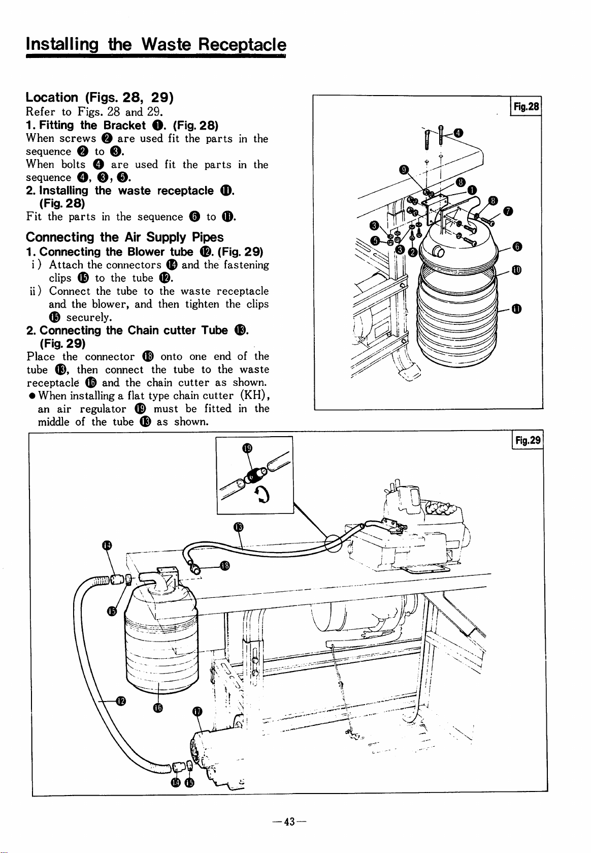
Waste
Receptacle
Location
Refer
1.
Fitting
When
sequence O to
When
sequence
2.
Installing
(Fig.
Fit
the
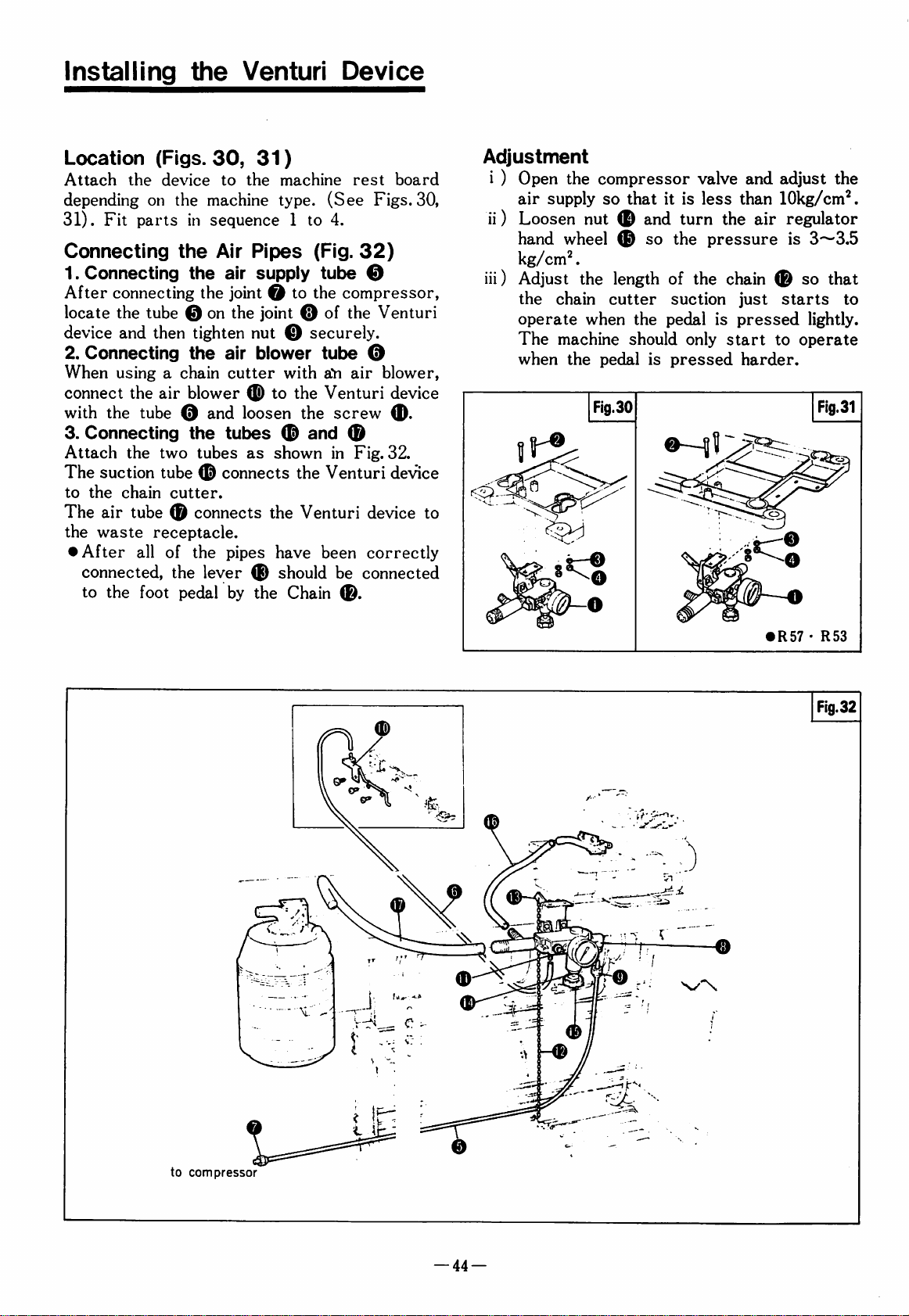
Connecting
1.
Connecting
i)
Attach
clips 0 to
ii)
Connect
and
©
2.
Connecting
(Fig.
Place
tube
(Figs.
to
Figs.
28
the
Bracket
screws @ are
o.
bolts O are
O,
o,0.
the
28)
parts
in
the
the
the
the
connectors
the
the
tube
the
blower,
securely.
the
29)
the
connector
0,
then
connect
receptacle © and
•
When
an
middle
installing
air
regulator © must
of
the
a
tube
28,
29)
and
29.
O.
(Fig.
used
fit
used
fit
waste
Air
the
receptacle
sequence @ to
Supply
Blower
tube
and
Chain
flat
tube
0.
to
the
then
cutter
onto
the
tube
chain
type
chain
as
shown.
cutter
28)
the
parts
the
parts
0.
Pipes
0.
(Fig.
and
the
waste
tighten
receptacle
Tube
one
end
to
the
as
cutter
be
fitted
in
the
in
the
0.
29)
fastening
the
clips
0.
of
the
waste
shown.
(KH),
in
the
Rg.28
-43
—
Page 45
Installing
the
Venturl
Device
Location
Attach
depending
31).
Fit
(Figs.
the
device
on
parts
Connecting
1.
Connecting
After
locate
device
2.
connect
3.
Attach
The
to
The
the
•
connecting
the
tube
and
then
Connecting
When
using a chain
the
with
the
tube 0 and
Connecting
the
suction
the
chain
air
tube 0 connects
waste
After
connected,
to
the
receptacle.
all
foot
air
two
tube 0 connects
cutter.
of
30,
31)
to
the
the
machine
in
sequence 1 to
the
Air
Pipes
the
air
supply
the
joint O to
on
the
tighten
the
nut 0 securely.
air
blower
cutter
blower 0 to
loosen
the
tubes ® and
tubes
the
the
pedal
as
pipes
lever
by
the
machine
type.
(See
4.
(Fig.
tube
the
compressor,
joint 0 of
tube
with
aYi
the
Venturi
the
screw
shown
the
have
should
in
the
Venturi
Venturi
been
be
Chain
©.
rest
board
Figs.
32)
0
the
Venturi
0
air
blower,
device
0.
®
Fig.
32.
de-sdce
device
correctly
connected
30,
to
Adjustment
i ) Open
air
ii)
Loosen
hand
kg/
iii)
Adjust
the
operate
The
when
the
supply
wheel
cm^.
the
chain
machine
the
compressor
so
that
it
nut 0 and
length
cutter
when
should
pedal
so
the
is
pedal
turn
the
of
suction
pressed
valve
is
less
the
pressure
the
chain 0 so
is
only
start
and
adjust
than
lOkg/cm'^.
air
regulator
is
just
starts
pressed
harder.
lightly.
to
operate
the
3~3.5
that
to
•
R57 • R53
Fig.32
0
to
compressor
—
44
—
Page 46
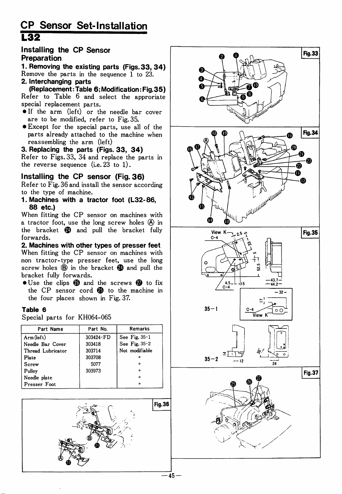
CP
L32
Sensor
Set-Installation
Installing
the
Preparation
1.
Removing
Remove
2.
Interchanging
the
the
parts
(Replacement:
Refer
special
•
•
to
replacement
If
the
arm
are
to
be
Except
parts
for
already
Table 6 and
modified,
the
reassembling
3.
Replacing
Refer
the
to
reverse
Installing
Refer
to
1.
When
a
the
forwards.
2.
When
non
screw
bracket
•
to
the
type
Machines
88
etc.)
fitting
tractor
bracket ® and
Machines
fitting
tractor-type
holes
Use
the
the
CP
the
four
the
Figs.
sequence
the
Fig.
36
of
with a tractor
the
foot,
with
the
(§)
fully
forwards.
clips @ and
sensor
places
CP
Sensor
existing
in
the
parts
Table
parts.
(left)
33,
machine.
use
or
refer
special
attached
the
arm
parts
34
and
(i.e.
CP
sensor
and
install
CP
sensor
the
other
CP
sensor
presser
in
the
cord @ to
shown
parts
(Figs.
sequence 1 to
6;
Modification:
select
the
parts,
to
the
needle
to
Fig.
35.
use
the
machine
approriate
bar
all
(left)
(Figs.
long
pull
types
33,
replace
23
to
the
1).
(Fig.
the
sensor
foot
(L32-86,
on
machines
screw
the
bracket
of
presser
on
machines
feet,
use
34)
36)
according
holes ® in
the
bracket ® and
the
screws ® to
the
machine
in
Fig.
37.
33,
34)
23.
Fig.
35)
cover
of
the
when
parts
in
with
fully
feet
with
long
pull
the
fix
in
O
o
View
K—I, , s
C-4
^
32-
Fig.35
Table
Special
Part
Arm
(left)
Needle
Thread
Plate
Screw
Pulley
Needle
Presser
6
parts
Bar
Lubricator
plate
Foot
Name
Cover
for
KH064-065
Part
No.
303424-FD
303418
303714
303708
5077
303973
See
See
Not
Remarks
Fig.
35-1
Fig.
35-2
modifiable
❖
//
Fig.36
—
45
0-4
View
K'
35-2
Fig.37
—
Page 47
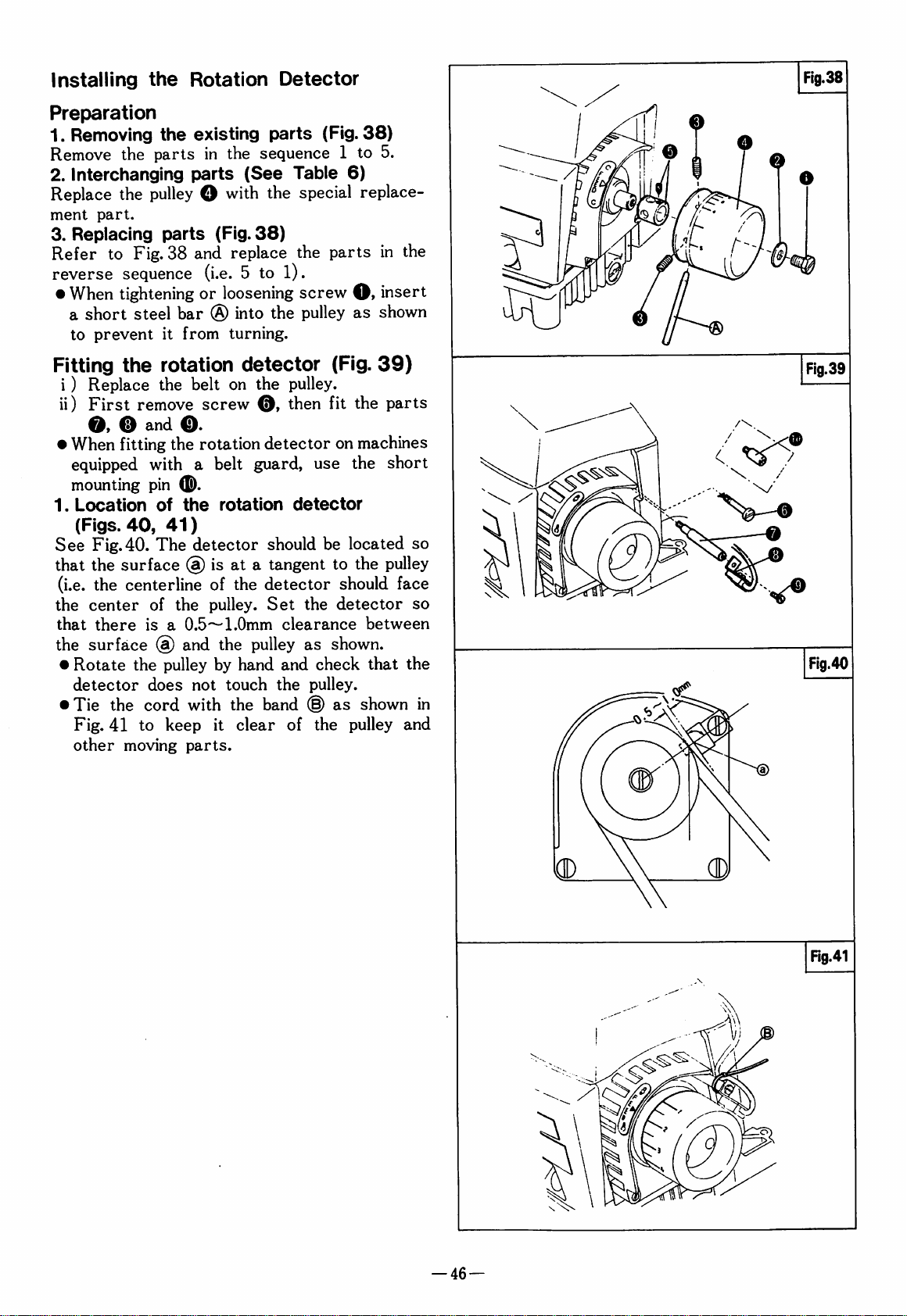
Installing
the
Preparation
1.
Removing
Remove
2.
Interchanging
Replace
ment
part.
3.
Replacing
Refer
to
reverse
•
When
a
short
to
prevent
the
the
parts
the
pulley O with
parts
Fig.
38
sequence
tightening
steel
it
Rotation
existing
in
parts
parts
the
sequence 1 to
(See
the
(Fig.
38)
and
replace
(i.e. 5 to
or
loosening
bar ® into
from
the
turning.
Detector
(Fig.
Table
6)
special
the
parts
1).
screw
pulley
0>
as
38)
5.
replace
in
the
insert
shown
Fitting
i)
ii)
•
When
the
Replace
First
0» ® a-nd
remove
fitting
equipped
mounting
1.
Location
(Figs.
See
that
(i.e.
the
that
the
•
Rotate
detector
•
Tie
Fig.
other
40,
Fig.40.
the
surface
the
centerline
center
there
surface @ and
the
the
41
to
moving
rotation
the
belt
O.
the
detector
on
screw
rotation
with a belt
pin
(E).
of
the
rotation
41)
The
detector
(a)
is
at a tangent
of
the
of
the
pulley.
is a 0.5-^
1.0mm
the
pulley
does
cord
keep
by
not
touch
with
the
it
parts.
hand
clear
the
pulley.
then
detector
guard,
should
detector
Set
pulley
band
use
detector
be
the
clearance
as
and
check
the
pulley.
(0)
of
the
(Fig.
fit
39)
the
parts
on
machines
the
short
located
to
the
pulley
should
detector
face
between
shown.
that
as
shown
pulley
so
so
the
in
and
Fig.39
Flg.40
—
46
—
(D
Rg.41
Page 48

CP
Sensor
Set-Installation
Installing
Refer
according
1.
£32-430,440
Use
the
the
machine.
For
screw
2.
Models
The
spacer 0 is
For
screw
•
Use
the
shown
the
to
Fig.
to
the
spacer O between
0>
other
0>
the
clips @ and
CP
sensor
in
Fig.
CP
Sensor
42
and
install
machine
model.
use a 1175-2
than
£32-430
not
necessary.
use a 1202
the
cord
43.
to
(Figs.
the
the
42,
CP
sensor
bracket @ and
screw.
and
£32-440
screw.
screws O to
the
three
43)
fix
points
Rg.42
E32-430'440
Installing
the
Preparation
1.
Removing
Remove
2.
Interchanging
Replace
part.
Fitting
Refer
•
Replacing
Refer
reverse
•
Table
Special
to
Fasten
belt
and
When
a
short
to
prevent
7
Part
Fan
Needle
Presser
to
Plate
the
the
parts
the
fan O with
the
rotation
Fig.
44
the
other
parts
Fig.
sequence
tightening
steel
it
Parts
Name
Foot
rotation
existing
in
the
parts
detector 0 (Fig.
and
fit
cord
so
moving
(Fig.
44
and
replace
(i.e. 4 to
or
loosening
bar
(§)
into
from
turning.
for
KH
Part
detector
parts
sequence 1 to
(Table
the
the
that
parts.
(Fig.
7)
special
replacement
rotation
it
is
clear
44)
the
parts
1)
screw
the
pulley
No.
301274
Not
44)
4.
44)
detector.
of
the
in
the
O*
insert
as
shown
Remarks
modifiable
-V
—
47
Page 49

KH
Controller-Installation
Identification
(Fig.
8.
45)
1.
INDICATOR
Indicates
2.
CLOTH
Lights
by
the
3.
COUNTER
Lights
detector.
4.
SEN
Adjusts
5.
START
Sets
and
to
cutting
6.
FINISH
Sets
and
the
to
thread
7.
POWER
The
Pilot
Lights
the
while
cloth.
when
ADJ
the
the
delay
the
change-over
waste
the
delay
change-over
chain
controller
Lamp
when
sensitivity
DETECT
the
the
sensitivity
time
time
power
the
and
Functions
ON
CP
sensor
fan
magnet
between
from
suction.
between
from
suction.
switch.
power
of
the
light
passes
of
the
CP
the
start
thread
the
cutting
is
switched
of
Controls
CP
sensor.
beam
is
the
sensor.
of
chain
end
of
waste
on.
broken
rotation
seaming
suction
seaming
suction
IXOBMtLOM
IKKaAfl
CLOTH
OCTCCT
.l^'^COUNTEB
ON
-'"—N
''EC
'
SEN
4l^PEBASUS.
INf
riST
* a a
IkOJ
STtRT
A-—"A
SLOW
Bl'MB
FBST
SLOa
m a
POWER
n m
I
Installing
Install
side
of
parts
•
The
power
correct
Installing
(Fig.
Fit
the
rest
board
47)
the
the
KH
the
machine
in
the
sequence 9 to
correct
supply
controller.
the
vacuum
in
the
KH
Controller
controller
under
table
as
10.
KH
controller
voltage.
Vacuum
switching
Be
sure
switching
device
sequence ® to
(Fig.
the
shown.
depends
46)
left-hand
Fit
on
to
select
device
on
the
machine
®,
as
shown.
the
your
the
Page 50
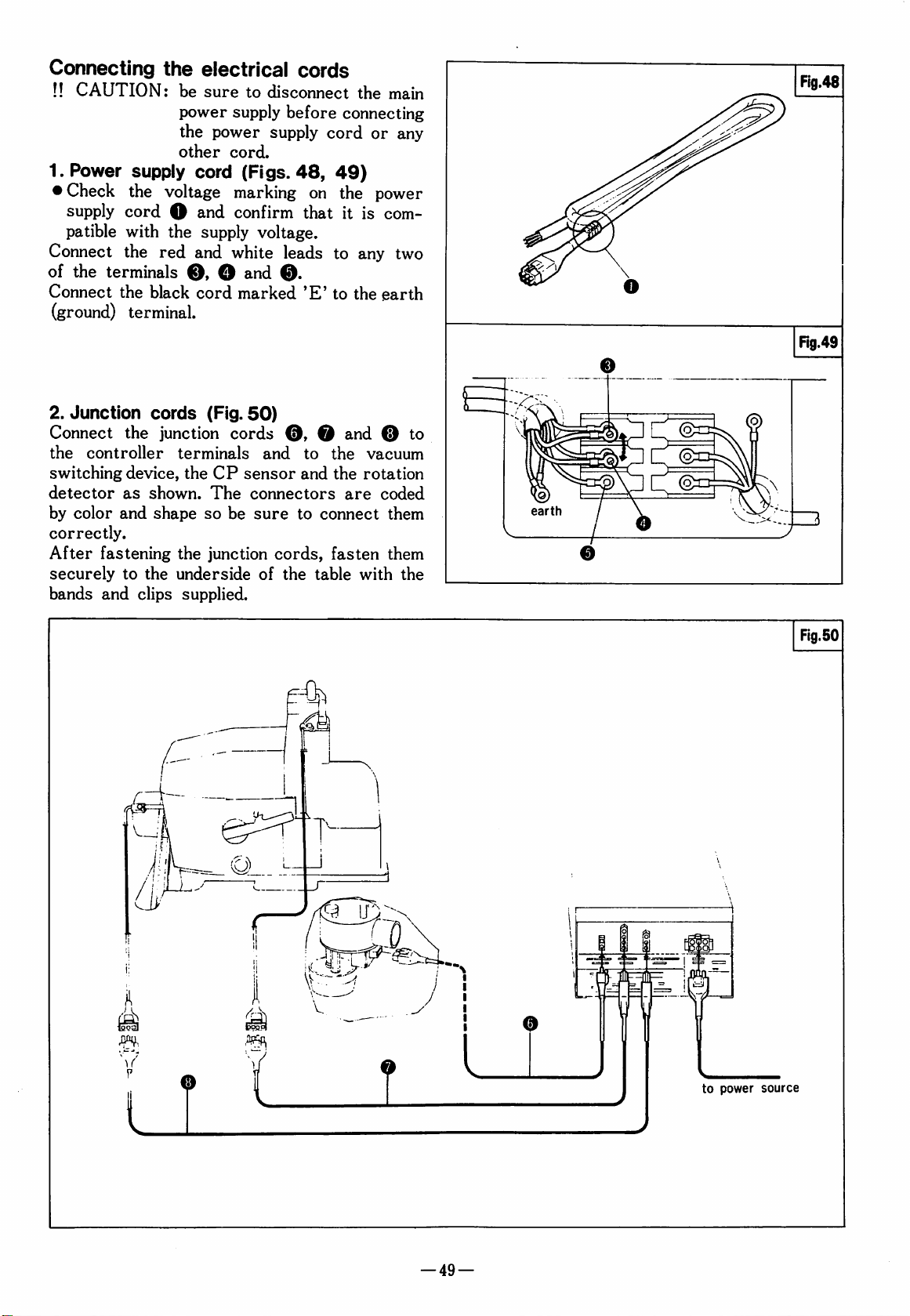
Connecting
!!
CAUTION:
1.
Power
•
Check
supply
patible
Connect
of
the
Connect
(ground)
2.
Junction
Connect
the
switching
detector
by
color
correctly.
After
securely
bands
supply
the
cord O and
with
the
red
terminals
the
black
terminal.
cords
the
junction
controller
device,
as
shown.
and
shape
fastening
to
the
and
clips
the
electrical
be
sure
to
power
the
other
voltage
supply
power
cord.
cord
(Figs.
marking
confirm
the
supply
and
white
O, O and
cord
marked
(Fig.
cords
terminals
the
CP
sensor
The
so
be
the
junction
underside
supplied.
cords
disconnect
before
supply
48,
voltage.
leads
0.
50)
0, 0 and 0 to
and
connectors
sure
cords,
of
the
connecting
cord
49)
on
the
that
it
to
'E'
to
to
the
and
the
are
to
connect
fasten
table
the
main
or
any
power
is
com
any
two
the
earth
vacuum
rotation
coded
them
them
with
the
earth
Fig.50
0
to
power
source
—
49
—
Page 51

Installing
the
Dust
Drum
Fitting
(Fig.
Use
O
•
If
top
chute
Locating
Place
the
the
51)
the
screws O and
in
the
same
the
machine
then
top
the
the
dust
table
as
cutting
position
has a standard
replace
O.
it
dust
drum
shown.
waste
fit
as
with
drum O (Fig.
on
coliector
the
waste
the
standard
the
the
left-hand
chute
one.
waste
special
51)
side
top
chute
waste
of
Connecting
1.
Connecting
(Fig.
51)
the
suction
the
tubes
tubing
O, @ and
i ) Place a connector O and a band
onto
the
ends
of
each
of
the
tubes.
ii)
Connect
then
•
Note
longer
correct
2.
Connecting
®
(Fig.
i)
Cut
insert
ii)
Insert
into
dust
of
the
•
When
without
be
sure
port
®.
each
fasten
that
the
than
length
tube
as
them
with
supplied
required.
before
the
Please
connecting
chain
cutter
shown
the
tube O is a little
51)
the
tube ® at a suitable
the
air
regulator
the
dust
drum
the
connector 0 and
drum
@.
Then
tube @ to
using
the
dust
an
automatic
to
place
the
the
drum
vacuum
(E)
end
connect
chain
and a chain
cap 0 on
in
band
clips
cut
it.
suction
place
as
shown.
of
the
connect
the
other
cutter.
switching
the
@
clip
Fig.
@.
it
to
tube
tube
it
to
cutter
device,
suction
@
51,
the
and
@
the
end
MHttsas
Fig.
51
—
50
—
Page 52

Checking
and
Adjusting
the
Sensor
Set
Adjusting
sensor
L32
(Figs.
To
make
53
and
8.
E32
(Figs.
To
make
54
and
8.
•
The
can
beam
of
the
sitivity
as
possible
needle
Checking
L32
Run
the
COUNTER
the
pulley
detector.
E32
Run
the
COUNTER
the
fan
detector.
the
52,
the
follow
53,
the
follow
optimum
be
achieved
at
right
needle
of
the
plate.
the
machine
indicator
magnet
machine
indicator
magnet
sensitivity
53
Table
adjustment,
the
procedure
54*
Table
adjustment,
the
procedure
sensitivity
by
placing
angle
plate.
to
to
the
Thus
CP
sensor,
the
reflective
rotation
slowly
lamp ® lights
lines
slowly
lamp ® lights
lines
up
of
8)
refer
described
8)
refer
described
of
the
reflective
to
set
detector
and
confirm
up
with
and
confirm
with
the
to
Figs.
in
to
Figs.
in
the
CP
sensor
surface
adjust
surface
it
as
the
the
the
that
up
rotation
that
up
rotation
CP
52
and
Table
53
and
Table
sensor
light
sen
parallel
of
the
the
when
the
when
^PEGASUS
Page 53

CP
Sensor-Adjustment
Procedure
o
'E
(0
c
CO
Q.
c
■«
Q.
Table
Sensitivity
Turn
the
fully
in
SEN
the
DEC
Controi
ADJ
direction
®
control
CP
Sensor
O
<:
O
a>
Loosen
Turn
SEN
ADJ
the
INC
O)
o
INDICATOR
direction
control
lamp
until
lights
in
one
up.
CP
Loosen
CP
If
and
screw O and
sensor
screw 0 and
sensor
necessary
adjust
in
the
(§)
direction.
in
the ® direction.
twist
the
the
CP
(§)
it
in
adjust
adjust
sensor
direction.
the
the
Indicators
One
or
No
indicators
Search
CP
sensor
imum
number
up.
more
for
on.
0^@
indicators
turn
on.
the
position
where
the
of
lamps
turn
of
max
light
8
4
o
Turn
the
in
four
completely.
SEN
the
INC
direction
lamps 0 to 0 light
ADJ
control
until
the
up
Tighten
Move
down.
screws
the
presser
0
and
foot
0
up
and
Indicator
turn
off
lamp 0 does
completely.
not
<
Indicator
completely.
lamp 0 turns
off
<
CO
C
0)
E
(0
3
(0
c
a>
Turn
fully
Turn
wards
0
is
the
in
SEN
DEC
less
the
than
SEN
INC
ADJ
until
half
ADJ
direction.
control
the
full
control
to
lamp
bright-
Break
beam.
(place
Res
tore
beam,
the
CP
cloth
under
CP
(remove
52
sensor
detector)
sensor
cloth)
light
<
light
INDICATOR
than
half
full
INDICATOR
than
half
Check
that
than
half
full
lamp 0 is
brightness.
lamp©
full
lamp 0 is
is
brightness.
brightness.
less
more
more
Page 54

Adjusting
the
KH
Controller
Test
ii)
sewing
i)
Perform a test
Check
thread
tion
at
iii)
Check
cutting
tion
at
Adjustment
Start
Adjust
chain
start
•
•
End
Adjust
waste
end
•
of
the
suction
of
If
the
then
FAST
If
the
then
SLOW
of
the
suction
of
If
the
sewing
timing
sewing.
timing
turn
direction.
timing
turn
direction.
sewing
timing
sewing.
timing
then turn
•
FAST
If
then
SLOW
the
turn
timing
direction.
direction.
check
the
timing
chain
suction
the
beginning
the
timing
waste
the
suction
end
timer
of
to
cutting
of
the
START
of
the
START
timer
of
to
of
the
FINISH
of
the
FINISH
thread
points
sewing
of
the
the
the
the
the
the
and
of
the
to
cutting
of
of
the
to
the
sewing
adjustment
changeover
waste
changeover
control O in
changeover
control O in
adjustment
changeover
chain
changeover
control O in
changeover
control O In
check
changeover
the
changeover
thread
the
waste
sewing
chain
seam.
from
suc
test.
from
suc
test.
(Fig.
55)
from
thread
suction
is
at
too
the
slow
the
is
too
fast
the
(Fig.
55)
from
cutting
suction
is
at
too
the
slow
the
is
too
fast
the
^y\|^CLOTHQl
^PEBASUS.
R7
•ON f SOLENOO > *
riNlSHav>i*f
OFF
POWER
n m
Fig.55
—^
Precautions
iv)
KH
chain
cutter
switching
i ) Be
sure
which
corresponds
voltage.
ii)
Since
the
electronic
sistors,
light,
high
Hi)
Do
not
yourself.
your
distributor.
with
device.
to
use
the
type
to
KH
controller
parts
avoid
humidity
such
exposure
and
disassemble
Should
it
automatic
of
your
consists
as
IC's
to
heat,
vacuum
KH
controller
power
of
and
direct
mechanical
the
KH
controller
malfunction,
supply
precision
tran
sun
impact.
contact
Scratches
on
the
will
So
on
the
of
the
cloth
v)
Do
not
be
broken
cloth
reflective
reduce
be
sure
lens
needle
at
allow
under
on
the
the
sensitivity
to
wipe
face
and
plate
regular
for
intervals.
the
CP
long
the
presser
sensor
face
lens
of
the
off
the
the
reflective
of
with a piece
sensor
periods
of
time
foot.
and/or
needle
the
dust
deposits
light
beam
by
rust
plate
sensor.
surface
of
soft
to
leaving
Page 55

PEGASUS
SEWING
Ca,
LTD.®
MACHINE
MFG.
4MP
 Loading...