

Page 1

INSTRUCTIONS
FW600
Cat.
No.
9A2009
A
'j
With
cover
December,
thread)
1984
FW400
High
First
edition
Second
(issued
edition
(issued
speed,
in
December,
in
2-
June,
(JtSlft
or
3-needle
1984)
1985)
'j
Without
Interlock
W
liS
(1984^^12
(1985:^6
cover
thread)
machines
UJ
ILL
t
cox
Page 2
1./n:;i. h ^yf-(±,
2. 5 y
>^-
0
#{tr
</;
$
5 y >
$ y >(7)#f^,
^rM?c75±.
^1*0
^:fo\
^(nLi3^rzVkiV\z, ^ y
tz<rz^\z^
C(7)|5&B^#li$g-ttTv^a 5 y
f^^co
>
(I^+5>rgeJt<
L ^ -tt^;^>^^
2.lt{ijEl
3.^l±IEl < ®$nT<-^^-r;6^o
4.:S
e$^30mm<" h 7
5.^
^
6.
<IXi'H^!t
bnrt-^^i-Tis
yJ^^'V'X
5 y X-An/iiScoM
^
iU r - y CO 2 ^^cO^cOPbI
L
^^^coifi^ n r c ^ ^
<
is
1
9
:fe'®M'-^i^Li-ro
V^ x 1"
(I
-fc 0 X
tJj'o
T
Hi:
A
3.r-7';i<'^li^n§
^^aJor
<
(h
^{±^
§li>
- ^ -
$
<-^0
yf-gr^oT,
q::.!:
tcff o T
vi ^ C
mm±(o^m
1. c i
(±
b'
46
CO 1 t!; H TbI
2.
li b iOT 5 y
^
A'r>
fz ^ y
$
CS
3. $ y
>;'^(i^
PbIC,
-9T<
>
>
5^/^
4.f^Ci{±b46T;!>^b
^Hf
b
A^I-t&^^T < Ai^cio
9
V t ^
^j-
1
liN
i:
yf-
7f-|:^oT<
<i:
(h ^ b
li.
531
(i'b
T < /i
oT*.^
co
<
^iS ^ b T <
b
juy— y (0 2 Tpccoi^co
^ > >I^D|jCOift
L
i
f^mtm-otzmz
1. 5 y > ^»LT<
2. ^ 4311
L T <
fnl
v^o
^ o /i
T-r
;!)^ C i
l+IS>
-"l--
5.^(±,
^>5ib®cOJi0Ib
<5ibT<
Page 3
24*30'
la
CO
I
1X1
=E—^—
'
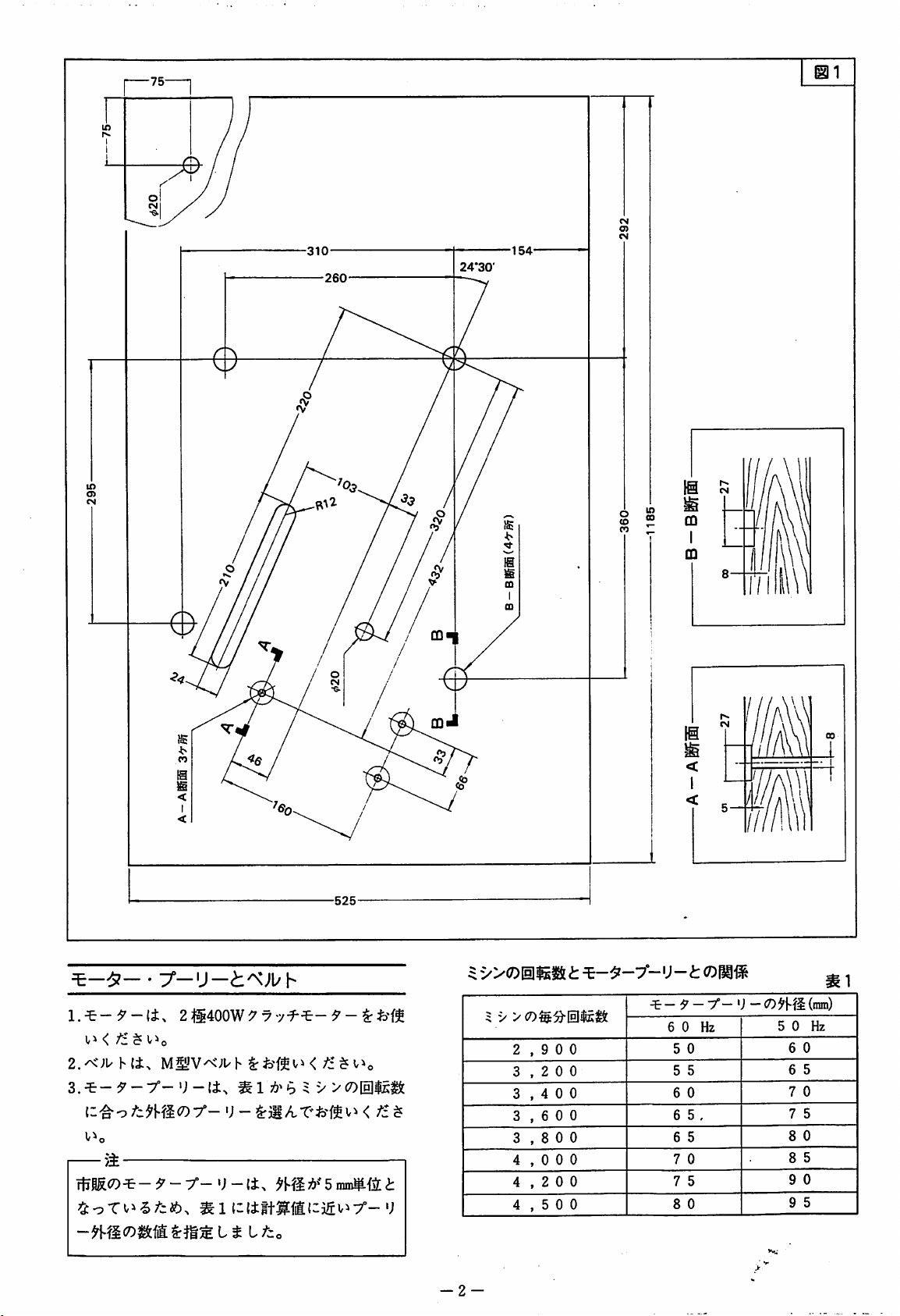
2@400W^7
Vi < /£ $ v^o
2.^";uh(i>
M§yv^;uh
{--^O
V^O
—
5i
rtfS^CD-^—^ ~ 7^—^J
^1
•;
-
—
7f-^-5'-|rfeM
;!?>b 5 V
<
5
nin#.{i
fz
i;
m
^
i^XDUm^ t ^-^-7 - 'J-t<Dmi^
V
><7)^:9'lEllEtS:
2
,900
3
,200
3
,400
^
3
3
4
4
4
,600
,800
,000
,200
,500
^-9-
6 0 Hz
5
0
5
5
6
0
6 5 ,
6
5
7
0
7
5
8
0
-f-
•;
-
5 0 Hz
6
6
7
7
8
8
9
9
m)
(mm)
0
5
0
5
0
5
0
5
-2-
Page 4
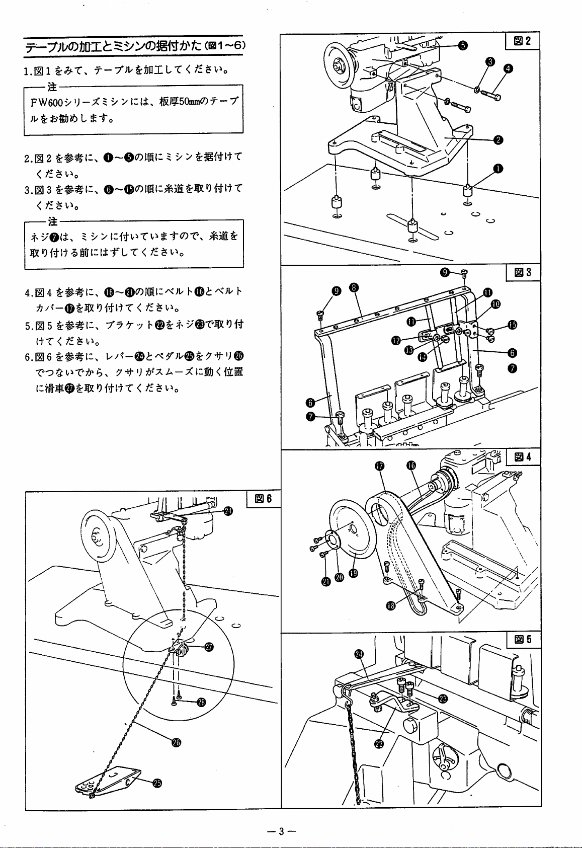
^
~
FW600'>U-X5
t
^i~o
V
^fi®50imn<7)T--/
0
2.ID 2 !:##{-.
<fz^
v^o
3.123
<
—
/i
4.12 4 ^##(-^
5.12 5 ^##1-.
(tr
<
6.126
T-o
^5:
b > :7
O~0<7))iill 5 V
>
©-®(7)Jiiih/nc;L'
^7^7
ix/■?-©<>
-if
'J x A - X
(zfj < {iS
h
-9-V©
-3-
G
Page 5

}¥x^UH(DiiS5
lfT<
$ t Th
Ol-^^ck9{::»LT<
#(i>
±Tizm^^ir<fz^\^^o
(117)
7i>^'o
/i
<h § >
:i-7
h©^§ifei6T.
U/<-®7&f;r-
y
^^vOi:
FW601AC
FW603AAX240
FW603AC
FW603AC
FW603AC
FW603ADX356
FW403AC
FW403A E X256
FW403A F X248
X240
X240
X248
X356
X248
#x^Og(a)
8.0tmn
❖
7.5niin
7.0nnn
>f
lO.Omm
❖
❖
CD
m2
(f
5 y >CO0|s:^[S]{i,
■f-')-m^'b^r.
OT'to
^3ll> ff^^giJ§;^0|El^C^c7)ii:Tl^^to
/i
fz^^fziyy
?t;6^i6T7!?^b>
5±
I^xm.
t^-(7)^^-^x^
^@fi$^<!:1^ffl^#i::«i:oT(i.
y-
'J
-
<fz^
^COi
:t;g|
:&I1I
^
0
F
W601A C X
FW603A A X240
FW603AC
FW603ACX248
FW603ACX356
FW603ADX356
FW403AC
FW403AE
FW403AF
^
240
X240
X248
X256
X248
®
15
[3
4
.200
f/
'/
f/
//
//
4,500
'/
'/
Ie
^
HRii^^0|^^.(ll8)
HR^gCOy'j
^I'^AfiT
zm^^'b
9^t->
::3
>
<
/£$
v^o
y U n
■^@(::ffi^&tT</i^i^o
>7i-'f
y'j 3 >
;i.
n^
t-f
-4
-
Page 6
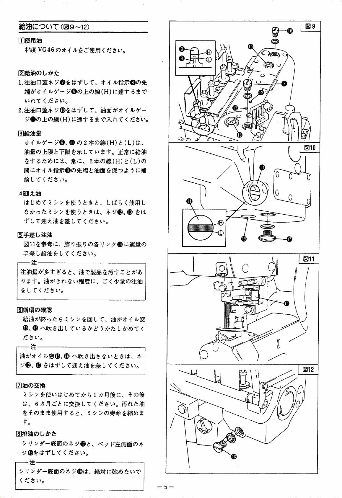
(1^9-12)
VG
46
C7)
^
)VY->0(D±0m{H)izmt
v®iSrlitXT.
v®(7)±o^(H)
^
izmt ^ t
</i $ V
\
TXtir < /i^Uo
t ^ )l^Y-
Ph^
izt^
I^LT
[Siffixjft
TLT3ai;l}6^^LT<
[5]^^
L
llll^##li,
—
>±
'Otto
^LT<
{mmomm
®,
©
fz ^ l^o
a
V©. © C7) 2 :^<DmH)
#(l.
<
fz I "y
>
t ^ it.
0O^t9CO#V
/£
b 5 V > ^0 L T.
§
ai L T1.^ ^ i"
;i/^©,©
2i^<7)m{H)t{L)(D
t
}ft®
r"
9
v©^ © ^l±t'LT3ffi^iA^IILT<
<!:
(L)
(±.
J:
9
L(±'b<f^fflL
v©, © ^
<
li
-f
l^'ibX<
/f^i^o
®
O)
it.
eijBXtiz^mir
2:^<r>ttmmt^t.
to
V
•; > r-mm(7)t
v®^lirLT<
——
V
•;
>
<
fz^
V^o
v©t.
v©(±^
<
ly><Dm^i:mi!bt
f§nfz'<^
^
k;&{iij®co
^^ttiz^isb ^ i^T'
9>\
t
-5-
Page 7

(013)
l-JiLT < /f $ v>
II ^ -
•; - G ^ 7°
ffl
(7)Bf
li
B-63
5^
—
6
Page 8
3
>iDiiS5
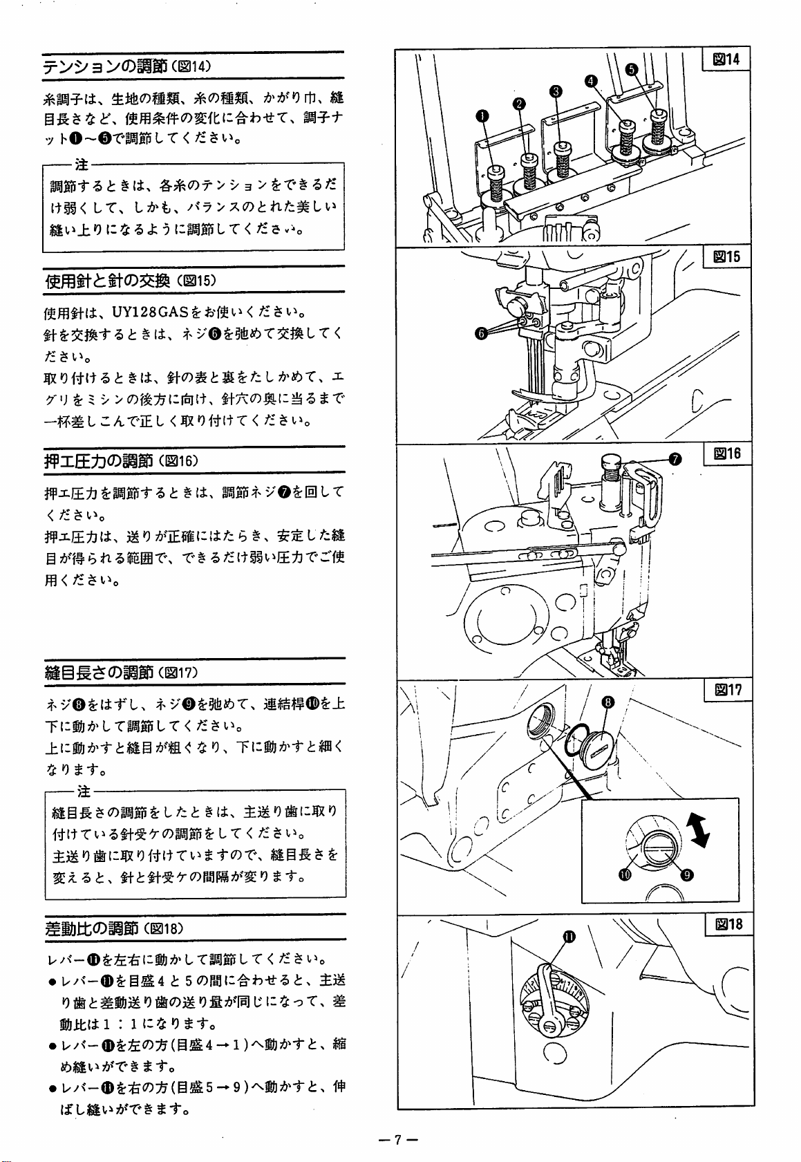
(iai4)
mm^i^<7)mti-'^h-ttr.
7
hO-©T«lT<
—
>i—~~"
#^(7)r>V3
ItIK
f^ffll+li>
^"'j ^ 5 V >(7)f^:^t:i[^(t.
#XEt)CDiiS5
W^J±ti^:m^i-^t^it.
<
J¥xii:^(i,
Sj{>^i#bn'5iEiir\
LT.
0
i: ^ ^
<fc
UY128GASffM^>'^<
#li>
3/uT'IEL<|X0itltT<
;'£ $ i^o
^M0
76?IE^i(I{±;^cb§^
^<y>^<Dtnfzmi^'
9
(^15)
^<D^t^^:fzl^^tbX.
L T <
If7\c7)^i:^^
(1^16)
M;r^v©^0tT
e/i(tiiv^j±:bT'rft
m^f-t
/£ 5 V-.0
mb
x
ST-
/i^v^o
^16
[@g$OiiS5
^^y®^l±-r"l.
Tl-iJ7&^LT|)gii5LT<
^'OtXo
/i
# [ t T V ^ <5
illtt^DiigiJ
•
U/<-®^i^4
0
ti[
(h
fiiklil : 1
•
U/<'-0i:ia<7):^(S^4--l)^W}7!)'i-ts
46^Slvi7&fT'§
•
^y^'—®$:q&(7):^(@^5-» 9 )^i!)7i?'i"
(f
LiS|v^;{>^'T'§^1-o
(1^17)
^>y®^§lbi6T.
tl-^ ^ C7)
ii
(1^18)
t
iz!i
Otto
115 ^ L T <
tc7)r%
L
Tli|gi5L r <
;^£ ^ V ^ o
/£
$
bMl ^ o
T.
<i:>
-7
-
Page 9
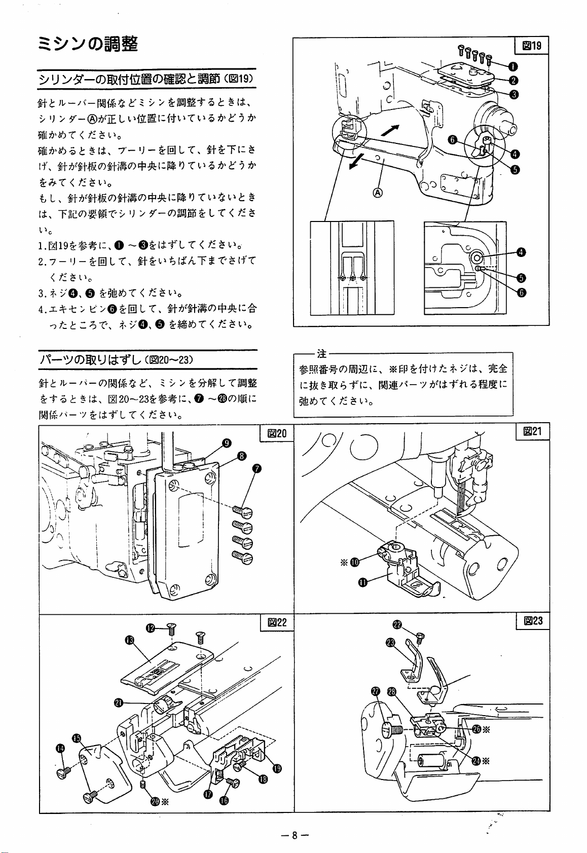
cbi9)"
)i--/«-IM«4t';
>
•;
>
?i;!)'i6«<!:
lf>
If
^h-X < ti ^ i^o
li^
-rm<n:^mx>
V^O
l.E?I19t:##(;.0
2.7-'J-^Ih]LT.
<
/:
3.
il±.
$
vO^ © K^kt>X < /i $ v^o
-> > SrMSi-S
')
>
If^t^^li'ATS
4.x^-t > e>@^lpllT.
-^tztZhXs
A'—^VOgSUt^-fL
Mf^:/v^7^[irLT<
^>v©.
©
(1120-23)
I120~23^##(:,©
/£
i
1
f}'
LT<
th7!»^"lf-;^(7)4.:^(:'^
#0e#-^C7)1^7Sf->
I - J-fe § IX b -f " t
~©C7)|i|Mli
?ife46T
v(i>
^
<
-f
"n
-5
UfS. I -
\e
-8
a
mz
Page 10
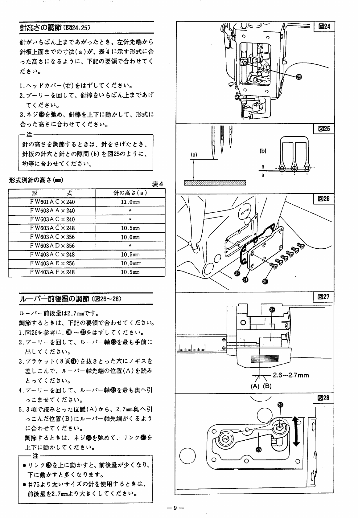
itB^CDiiSr(IS24.Z5)
W^^(a):d>\
1.^7
[—>$
K7:?^<-(^)
T < fz^\^^o
mJi<r>^^tiitcr,Bm
(mm)
m
FW601AC
FW603AAX240
FW603AC
FW603AC
FW603AC
FW603ADX356
FW403AC
FW403A E X256
FW403A F X248
^
X240
X240
X248
X356
X248
^
4
iSrli-ftT<
(b)
^[2]25<7)J: ^ C.
$ ( a
ll.Oiran
❖
❖
lO.Sinm
lO.Onun
'/
10.5mm
10.0
mm
10.5mm
&
@25
(a)
«4
)
(b)
jb—A—|u^S(DiiS5
;i/
—y\°—gfjf^^ti2.7inmT'"i"
1.I126^##I2.
€)
(1^26-28)
~®trli-r"LT
2.7'-';-^0LT.
thLT<
3.
7'7 7 7 h (
fz^\^>o
8M®)
^lz/vX\
ioT < /i^v^o
o
Zt-^X < /£
5.
3
i^lni-ai
—
>±
^
i o 7^fiS(A)
^(±.
y\zmi3^-rtp<^^^tto
•
#75ck0i:(.^-if>f
irf^fi^2.7min3:'9:^i < LT
o
<
i: o /-7\i: ^ ^'7
:d* b %
2.7inm-^^5l
-5
'J
>
§li.
<
3:7
iml.iirtlitnl
^
2.6~2.7mm
(A)
(B)
@28
-9-
Page 11

Ot
fV
I
8
s
M-
ro
CO
/-N
vg^
v:
(k-
ae
•
t
<r
W
W
Or
f>
4
A
av
✓X
(>.
c~
RV
0
^
Ulc
rw
I
1
M,
d
1
1
-<0
X
—t-
3
«•'
v^.
?>1
SB
s?
M
f
f>
✓X
1
h"
OV
<-
P?v
m
rr
fV
10}
0
3
3
Opf
o
Ok
c
9+
0
nfr
M
o
nS
RV
bUQ
■^'
'
v:
1
CO/o
o
CO
o
1
-^o
Nv
RV
3
R^
«
(
w-
3
9«-
-A
i
r»
tt-
n5>
&-
■'
0.3'>-0.4mm
I
fV
t—'
h-»
CO
RV
ii
*vl.
to
1
ilSI
JBH-
fc
H'
—
v
O
QV
#
'i
fW
1
1
d
<-
15-
il
9>l
9t
O'
rv
■=n
VJ;
e
p?v
0
A
t=H
j
I
0
tr
'~\
m
o
vf'
:ao
'
s
f>
(k
A
yx
v;
-^'
f
<-
•m
n>
r!
i
<-
o
?>"
3
M
n>
9+
w
c~
0
0
V
l"
X
n
3
ii-
fX
a<-
0
tJ.
1
s
s
dv
»
(
10
<r-
f
OV
o
Co
p^V
mi
•a
?
o-<
f>
RV
o
n
c
0
w
fV
'
ct:
:ii
)
<
tf-
n>
Pli
(k-
5+
'~\
rA
ij-
(H-
y\
r-
A
"
1
X
I
vj„
z
0
Page 12
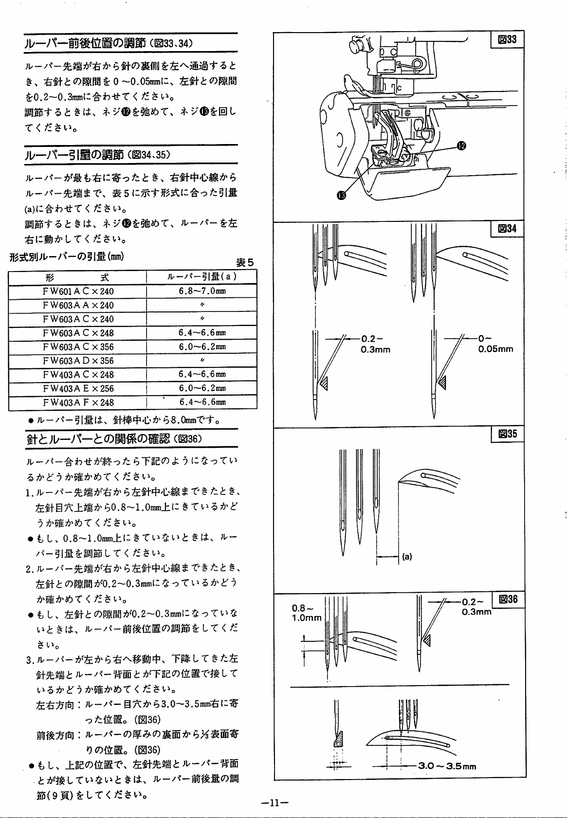
;i/-y\°-§Ti^fig0iig!r
§:>
:&t1-,i:COPOTt:0~0.05minli.
^0.2—0.Smnl^'^h-^X
^>v®^5fei6T.
T<
/£
(1^33.34)
<C
^■'V^^IeIL
^33
>11/—A°—glgCDIigi
(1^34.35)
(a)(:'^h-ti-T < fz^\^^o
FW601AC
FW603A A x240
FW603AC
FW603AC
FW603AC
FW603A
FW403AC
FW403AE
FW403A F X248
•
;F
—/N°—
—<75 5 Ifi
(mm)
X240
X240
x248
X356
0x356
X248
X256
tt<h>ll/—A—^(011^0
;u—y\°—5l:g( a )
6.8—7.0nraj
6,4—6.6mni
6.0—6.2nini
6.4—6.6nrai
6.0—6.2nini
6.4—6.6mm
b8.0min*Ci"o
{ili
(@36)
f/
❖
0-
0.05mm
tf
g|35
;u
—/\'
—
^ i"
9
IJW - ^
9
• i L.
-f - ^
0.8-1.Oiran±II#Tli^i^<h
T < /i ^ I.^o
< fz^^^o
/^^-?lffl^lllBi5LT<
2.
;i'-^
fe
tfi
COPtFal;{>^"0.2~0.3iran(l
<
tz^\^o
•
{>1. fcli*<i:OPtPB^7{)^'0.2~0.3mm(:^oTl^^
^
v^o
* ;U
—>'^°—@7a:7{>"b3.0—3.5ramq&(-^
o^cfiSo
bTIC^^cfc
b £ ti-
4-
9
^D ^ T'
b0.8~l.Oram±(: # T^
§{i^
rz^l^o
h
tX^tztt.
^ o T
yi^ix
(1^36)
#
-5
?!»'<!:'
)\^-
(i:-
^fzi£
^
9
^
8~
0mm
(a)
0.2—
0.3mm
®36
'9(7)fi[So
•
tL.
±fe(7)(3[ST\
liS(9M)^tT<^i$«/^o
(1136)
-11-
■rt*--
m—
5
mm
Page 13
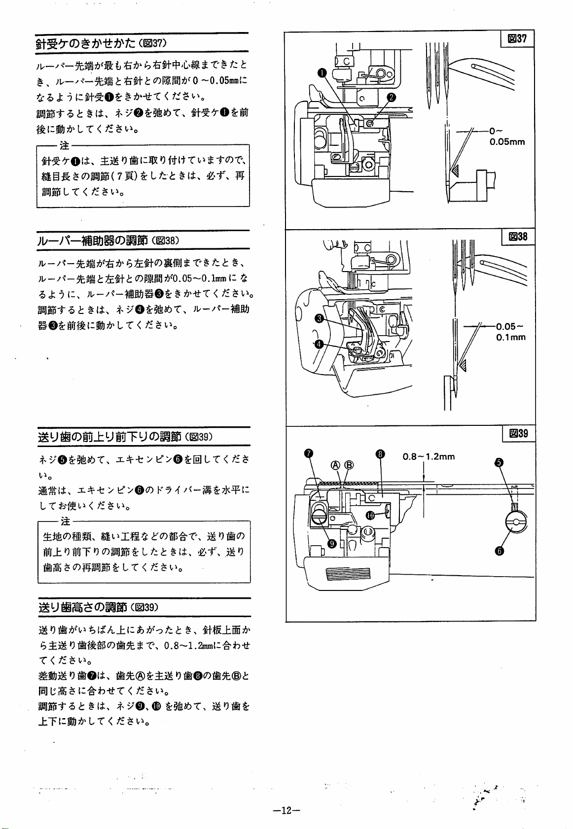
®37)
IJ-
@37
;U—
^ , ;U—
t^hXn
t3
|)||iSl-'5<h
>±—
IT
<
;b-A-^atl^CDpg5
; U - / ^ ^ £
§{i.
i)
i
^tl"
t
^
;f>
v©^§ife46T.
<
(1138)
tl-1C7)
^
0
~0.05nini(C
fJ:
$
it'^^OIrM
. 0 5 ~ 0.
T' ^ t
Imm
11
,QaS
o~
0.05mm
m
w
^
rc
0.05-
0.1mm
3MU^0lii±UluT'Jg)iii!i
^-v©^§tbfeT.
JC^-t>e>©c7)K7^v<-^^7K^i:
ii±»9HuTO(7)M^l;^;£:
'^±3iOliff^S15C7)#5fe^-r\
r
<fz^
^iS}i'9®©li>
iigiSi-^<i:
±Tl^ib75'^tT</£$v^o
Ji^-b > t''>©i^lHlLT
((^39)
#^(§)Sri)^0jir®cO®5fe(i)^
^(±s
(mag)
#(i.
0.8-l.2ma\Z^h^t
<
iiOiicT)
0.8—
@39
1.2mm
•12-
■ .
*»t
Page 14

3-
Q
lif
m
©
Q^,
4-»
to
CO
©
^
^
9^
o
3
^ ^
^
5$
p^
imt
3;
Ot:
p^
mi
®
^Df
^
e
w
n
#
>1-
©
©
©
'
r-
m
H
9fr
(V
4
(
S
5
S
tHWX
©
'^
CT
n
y
(6
3
«V
4
W
4-»
00
y
$
l-»
9+9+
«£>
y
^
9+
CO
O
y
$
9+
Off
-^'
y
ij.
A
c
S
9+
'
'
©
q:
9t
^
r>
^
p?v
^
o»
c
'p
's>
s>
©
r>.
I
n
'S
b"
vT'
Si
O
I
Ii^
f>.
1^4
&
n
rov
M
wi:
tJ-
0>
y
^
0
"
O
vS
3
ru
null
<r
?
III
6^
p^
iy
<-
Of
y
y
©
e
4
C>«
4
XV
©
e
y
y
i:
3
n
iSS
18.0mm
19.0mm
20.0mm
0
B»U
BUtt
!$
Jtg
c
1
r-
mi
ti-
isB
h-
4
vT'
v:
v:
Of
b-
Of
J
©
{^
&
p^
©
H
3
-tI
r^
Hf
xa^
O
<"
o«
ir
9>
•''V
vJ
a.
f>
fV
y
(t
3$
>
p^
©
*y
0
0^
xa^
X;
A
&
y
xa^
9+
0-'
Off
y
fV
3
•y*!
V
M
y
iW
A
y y
3$
s,
H
■^'
©
y
fc
<-
r>»
A
Of
O
9+
iy
62113
9^^
O
w
iutH
IN9
<-
iy
9+
-fr
p^
CO
O
Of
n
T)
3
3
-^'
4
(
-^'
f>.
?>J
p^
•H6
1
3
Xaja
0
m
•KVy
u
<r
(7'
/V
(»
(V
Of
vJV
f>»
fV
Of-
<-
m
fit
1
0
vT'
Of
W
c
va^
5$
A
✓N.
go
m
sT
4
(
w
a-
iP
>}
vaj.
xa^
■^'
©
^r
1^5
H|>
©
3
n
Vj»
///
©
y
n>
3
Wt
T#
fe
b"
m
)<')l
□>
PJf
©
p^v
©
HI
H
m
3
n>
p^
1
1
V.
^O
V
3 3
ve^
V
3
y
©
9+
o
3
S
1
H
3
{»
2{:
c
xnn
tmrn
M
9>
a-
1
1
V
y
Or
a-
9t
-!>
A
n
ytm
Sin
3
r>
HBi
t^
^sS
a
©
li^
vT'
VO^
Piv
w
w-
xa^
p^
c
w
a-
w-
Na^
r>*
A
r*
rA
-V-
Of
vT'
w
fV
O
3
i./
<-
0
I
OJ
Page 15

^
^(i^_hi;
•')
©^N I T, X h 7 T';r^
<7)n.K
msrM(r>^m(n^^^^b
A ® s
T-^'j23mmlI ^ S
Ji, _ y
V^
^<^>'),
^< L ^-To
f) 0 ^Jii6
ij-<
(1143)
J:
•)
i:-^h-tf-T<
i"o
-5
(h
^
>0;!?'
< ^ •')
tto
V©
'J
")
ai
@43
>
f
L
to
0
@44
if5LJ^iiiUa)iiM5
(^44)
^^»)©C7)B
ot
<"±^r^<
MBi5i-'5 ^ t{i>
T. X h 7 7°^^
<
^i:
9
i
0
^<9.
fp U H
1.^6(1.
(a ) ^
-ti-T < v^o
f)©
^5ii6 « <i:
;fc-<
bt<!:'>< ^ f)
U
gij(I(7)-ttr
^El+7)>b5.0~5.5mm(7).i5(g)t;^g|^P^J^7{)'-<
7'b^7
h®^0i^7&'b>
J:9t:'^h-a-T<
^>v©^3tbi6.
y©7!)^'U > X'CO-iaJ
<iZe
(1^45)
;^^0©^Ifi]L
»9
Z^(D^4i:i-
f)
th
S-To
L
1.^^1-0
^^7©,
<
m'om'o
^
FW601AC
FW603A A x240
FW603ACX240
FW603AC
FW603AC
FW603A
FW403AC
FW403AE
FW403A F X248
X240
x248
X356
0x356
X248
X256
im)
5.0-
5.5mm
10.5mm
10.Gram
9.5mm
@45
to
00
lfPUIiUSCDiiS5
m^m<oo<7)m^&ii:
1.^7
2.-f 7 h®^5fefcT. n 7
K:<7/<-(:&)
<
/£
^
•9^
(1146)
i^xto
^l±rLT<
K©^;£^(-i!j7&^LT
^ ^ 1-0
-14-
@46
14mm
Page 16
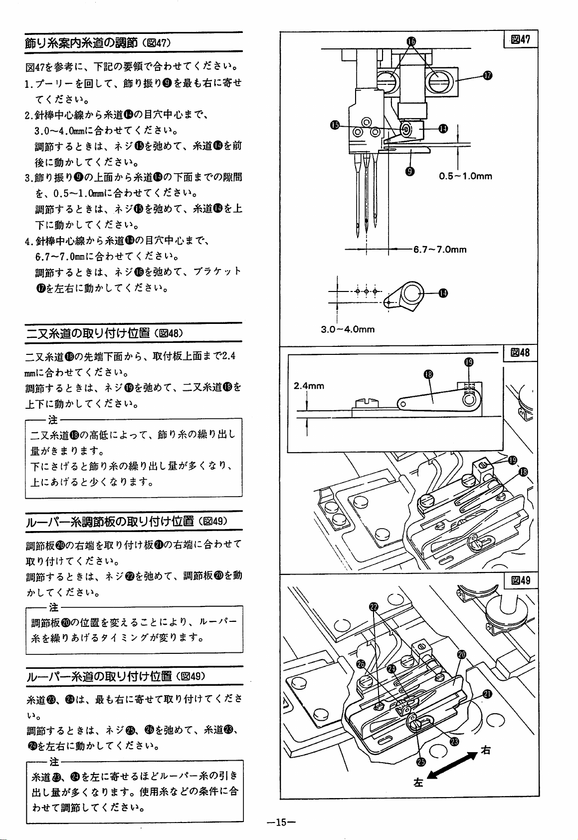
ci^47)
1.y-u-grHitT,
X<fz^
2.
3.0~4.0inin(;'^b-ltT < /£ ^ V^o
b
X\
J
,
@,
(Q)
--
@47
A
(Q)"
r
/£$v^o
®
o±®
i:.
0.5-1.0iran(:-^h-li:T<
r\zm^'ix<fz^\.^o
4.
&.7-7.0niiiii:'^h-ti-T
Mt^<!:§:
li.
~3^^Mg)g)?UWttlNlM
rx^ii^co^fe^^T®
±ycm^'ix<fz^i^o
_.^
i:Z;^5:jI®<7)i^fg:{ii;oT,
b
b
4^y®^§fetoT.
g
7=^4^ t X\
<fz^
(1^48)
7&^ b >
mtm±^
T® t x^<Dmr^'\
;^£$vio
gfp0^(7)^0
XyX-yh
t
X2A
tB
W
3.0~4.0mm
2.4mm
L
'4
^
^
^
■6,7—7.0mm
0.5-1
0mm
T1-^
^0#ltT<
|^li5t^<J:
^^lX<fz^\.^o
jb-y\-^^cDi;m^c-tlizM
Iigi5t'5<h
—
if-5
<h
§li.
#l±>
IfP 0 ^
(7)^ 0 iB L fl
/£$t^o
f>y®l:$fetoT,
5
f->y®^
tT < /£^i^o
®tr§tfei6T.
c^49)
xi-o
(1149)
;^3i®^
0.
@49
fBtfi7&^'#<
b-<i:T^gi5LT<
^5:0^1-0
/£^Vio
-15-
Page 17
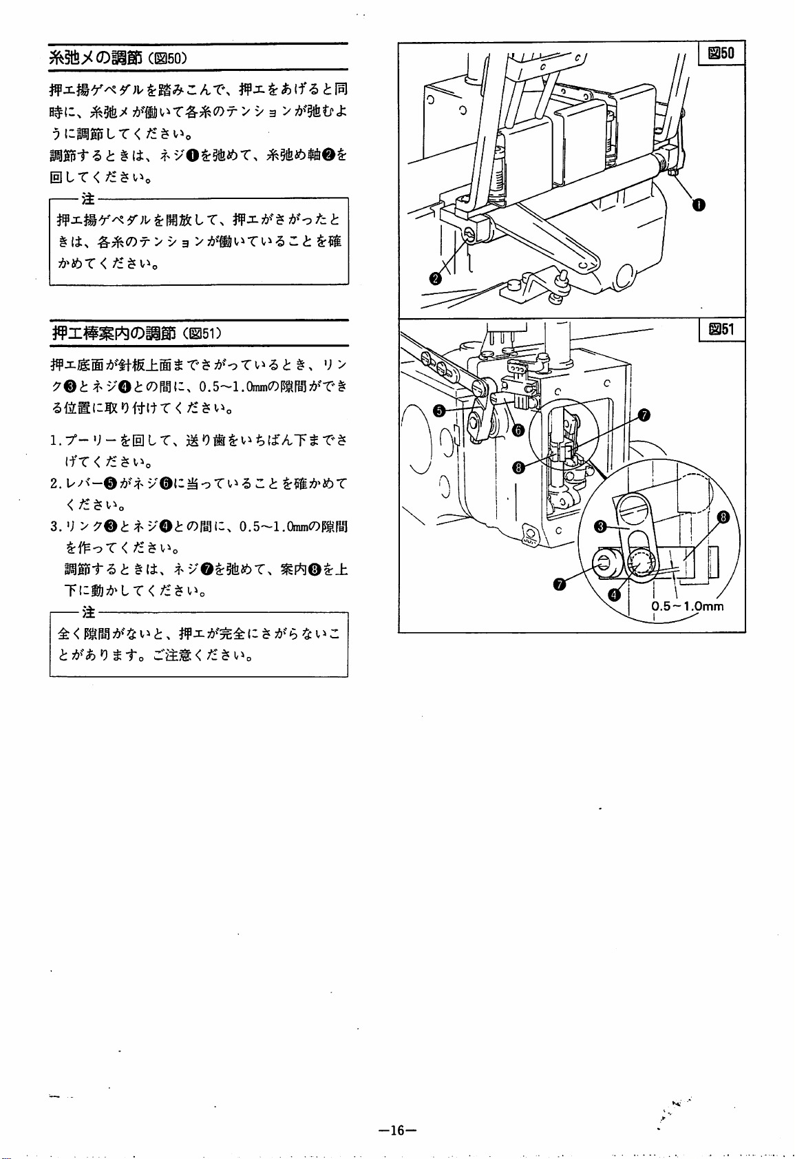
S^§te;><a)iiS5
H#i;.
;^§fe^
#lix
^^<Dt>
7&^i6T<
ff
X#^p*gCDiig5
7®
^
(1^150)
y
3
/£
(11151)
VO<1:^7)Paid.
> V 3
>7i>^"§fitfc!:
0.5-1.OinmCT)
t
ifr
<
2.
3.
'J
y9Bt^^yOt(7^mi:-.
l^@5t6<J:
'r\zm^'ix<fz^\.^o
—jt
v®t;^oTi^6
§(±.
O.S-l.OmmCOPtrBl
H^yOz:mibX.
^?S;{>»toT
mP^Oi:±
0.5 — 1,0mm
-16-
Page 18
u
^
3^
mm
C
s.p.m.
FW601ACX240
FW403ACX248
FW403AEX256
FW403AFX24B
FW603AAX240
FW603ACX240
FW603ACX248
FW603ACX356
FW603ADX356
4.0
4.8
5.6
4.8
4.0
4.0
4.8
5.6
5.6
2
4
1.4 - 4.1
1.4-4.1
0.8 - 1.4
-
1.4
8.5
10.0
8.0
4,200
4,500
4,200
U
>
•
• U r—t—tl'^^ftv-'-Cv-'^to
h
hu-—-f—
h
IJ
>
• f |-|j5ic7)jR{c
0 it,
v> i tc
Page 19

MEMO
-18-
Page 20

INTRODUCTION
This
booklet
operation
and
machines.
before
derive
DAILY
Before
1.
2.
3.
4.
5.
6.
7.
After
1.
2.
3.
use
of
the
best
MAINTENANCE
starting
Check
damaged.
Check
Check
Check
formed.
Check
lines
Check
lubrication
Check
while
Clean
needle
If
it
rapair.
Place a dust
needle
needle
threading
thread
oil
of
oil
oil
oil
running
close
the
plate
any
trouble
to
the
of
machine.
plant
contains
maintenance
Careful
indicator
gauge.
is
parts.
monitor
work:
reading
the
machine
use
from
work:
is
in
sound,
is
correctly
is
correct.
chain
of
not
color
the
machine.
it.
tip
short
Especially,
and
looper.
or
irregularity
mechanic
cover
over
some
of
of
will
condition
set.
about
is
between
for
is
changed
for
the
machine.
notes
the
SOnan
FW
this
help
length
on
series
booklet
you
and
the
the
manual
to
green
clean
around
is
found,
report
adjustment
the
to
not
is
two
or
FOR
SAFETY
1.
Make
sure
2.
Be
well
with
energizing.
3.
Turn
the
4.
Be
an
5.
Make
the
off
work
sure
electric
sure
checking
6.
Make
when
replacing
NOTES
1.
Run
the
2.
In
after
drops
3.
Keep
level
lines
4.
Change
one
5.
Thread
the
ON
new
maximum
using
stop-page
of
the
indicator
of
month
illustration.
Belt
careful
power
Motor
table.
to
turn
breakdown.
to
and
cleaning
sure
Motor
the
machine
Needles,
USE
machine
for
the
machine
oil
manually.
machine
oil
gauge.
oil
entirely
in
operation.
your
machine
Guard
in
connecting
source
Switch
off
Power
turn
off
has
etc.
at a 20%
the
for
some
oil
is
always
at
is
properly
the
and
whenever
Switch
Power
the
Switch
machine.
completely
requires
less
speed
first
one
month.
for
the
first
time,
lubricate
level
so
that
between
the
end
of
correctly
according
fitted.
machine
checking
you
leave
in
case
of
before
stopped
threading,
than
time
and
2~3
the
oil
the
two
the
first
to
-20-
Page 21

-19-
Page 22

CONTENTS
Driving
Table
Presser
Turning
Machine
Silicone
Lubrication
Threading
Regulating
Needles
Presser
Stitch
Diff.
Cylinder
Disassembling
Needle
Looper
Looper
Looper
Synchronizing
Adjusting
Adjusting
Checking
Needle
Looper
Feed
Feed
Needle
Needle
Needle
Looper
Spreader
Setting
Spreader
Spreader
Setting
Setting
Setting
Thread
Presser
Specifications
Operators
Table
Parts
motor
cutting
foot
oil
foot
length
feed
height
pulley
and
lift
direction
speed
for
the
thread
pressure
control
ratio
adjustment
adjustment
adjustment
avoiding
holder
height
and
adjustment
needle
clearance
distance
the
relationship
guard
adjustment
auxiliary
dog
tilt
adjustment
dog
height
thread
thread
thread
thread
guide
presser
support
takeup
thread
position
of
stroke
thread
position
position
position
release
bar
of
of
of
adjustment
guide
Manual(For
of
Adjusting
Checker
adjustment
motion
adjustment
takeup
adjustment
guide
adjustment
and
belting
machine
of
H.R.
tension
installation
machine
device
adjustment
looper
between
setting
and
looper
between
needle
needle
between
adjustment
spring
adjustment
adjustment
adjustment
adjustment
spreader
adjustment
spreader
looper
looper
thread
thread
thread
operators)
Standards
timing
and
looper
and
looper
needle
and
guide
guide
plate
eyelets
for
FW600,
point
looper
FW400
^
22
23
24
24
24
24
25
26
27
27
27
27
27
28
28
29
29
30
30
30
31
31
31
32
32
32
32
33
33
33
34
34
34
35
35
35
35
36
36
50
•53
-21-
Page 23

Fig.1
-310-
260
24*30'
-154-
o Si
to
CO
C
0
t)
<D
CO
^
CD
1
OQ
I' /A \ 1
rtl
I! / '
\
h'\\
\\
A\i
\
li
U
DRIVING
The
the
following
1.
Motor:
2.
Belt: V belt.
3.
Motor
MOTOR
machine
Clutch
watts.
pulley:
-525-
PULLEY
should
use a motor
AND
BELTING
and
specifications:
motor, 3 phase, 2 pole,
Type
M
Select
referring
an
appropriate
to
Table
1.
belt
of
400
pulley
Relation
Machine
between
speed
2
,900
3
,200
3
,400
3
,600
3
,800
4
,000
4
,200
4
,500
Machine
(s.p.m.)
0
(0
<
<
Speed
Motor
6 0 Hz
5
0
5 5
6
0
6
5
6
5
7
0
7
5
8
0
c
o
0>
1
and
pulley
m
•/Aw
/
/;
h\\
i I i
i
Motor
Pulley
diameter
5 0 Hz
6
6
7
7
8
8
9
9
Table
(mm)
0
5
0
5
0
5
0
5
1
-22-
Page 24

TABLE
INSTALLATION
1.
[—
For
thickness
2.
3.
—
Remove
guides.
4.
5.
6.
CUTTING
Refer
to
Fig. 1 and
Note:
FW600
50mm
Refer
to
Fig. 2 and
in
sequence.
Refer
© — ®
to
in
Note:
Screw O before
Refer
to
Fig. 4 and
Cover
Refer
Screws
Refer
©
position
®, © — © in
to
Fig. 5 and
©.
to
Fig. 6 and
with
Chain © and
where
(Figs.i-6)
series
is
Fig. 3 and
sequence.
the
AND
MACHINE
cut
the
table.
machine, a table
recommended.
install
the
machine O —
attach
attaching
attach
Belt © and
Thread
the
sequence.
attach
connect
chain
Bracket © with
Lever © to
attach
Pulley © to
can
move
smoothly.
of
plate
Guides
thread
Belt
Pedal
©
the
©
-23-
G
Page 25
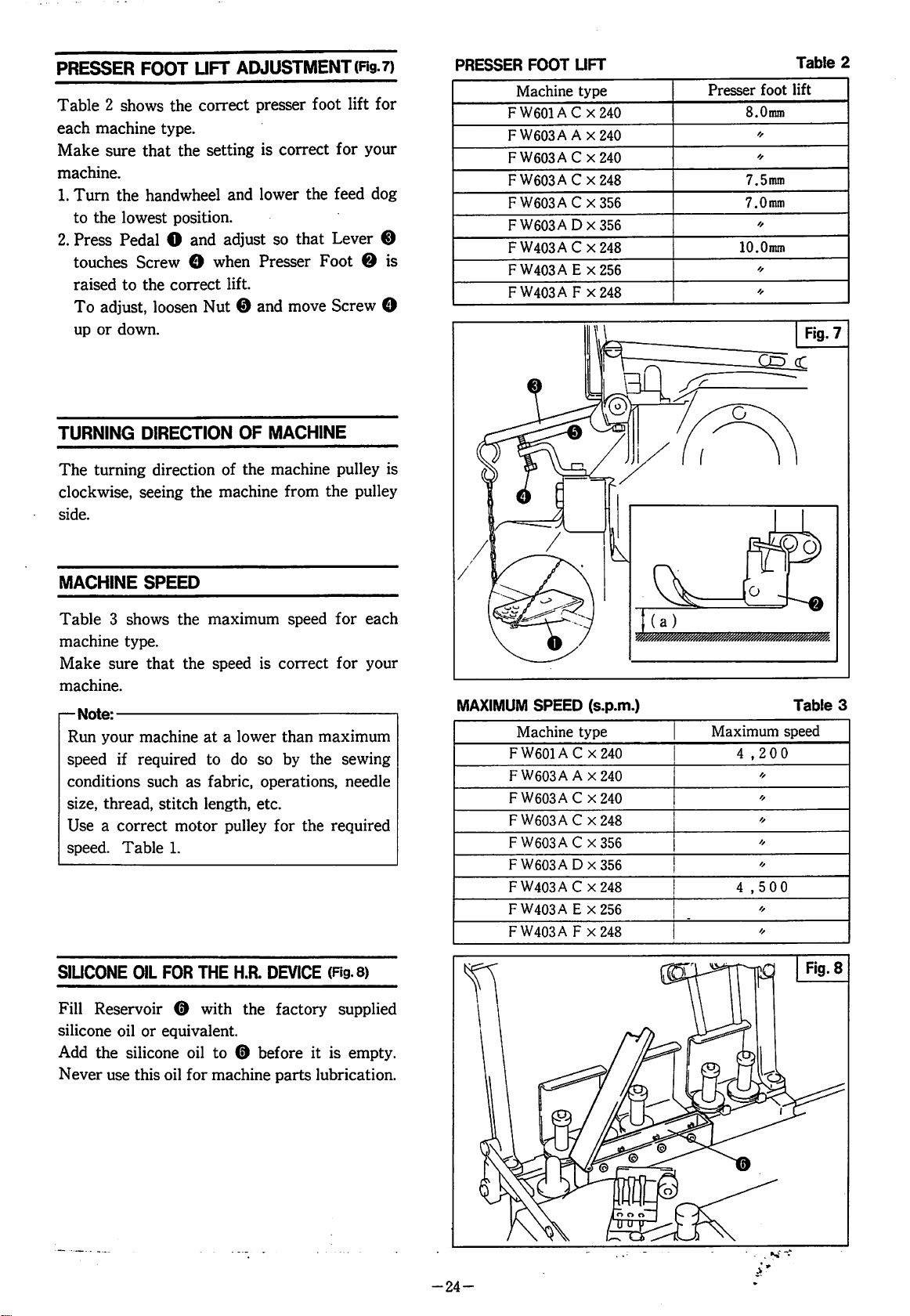
PRESSER
FOOT
Table 2 shows
each
machine
Make
machine.
1.
2.
sure
Turn
to
the
Press
touches
raised
To
adjust,
up
or
type.
that
the
handwheel
lowest
Pedal O and
Screw O when
to
the
loosen
down.
UFT
ADJUSTMENT
the
correct
the
setting
and
position.
adjust
correct
lift.
Nut © and
presser
is
lower
Presser
foot
correct
the
so
that
Foot © is
move
(Fig.
7)
lift
for
for
your
feed
dog
Lever
Screw
©
O
PRESSER
FOOT
Machine
FW601AC
FW603A A x240
FW603ACX240
FW603AC
FW603ACX356
FW603A
F
W403A C X
FW403A E X256
FW403A F X248
UFT
type
X240
X248
0X356
248
Presser
8.0nmi
7.5mni
7.0
10.0mm
foot
❖
mm
❖
❖
'f
CDcC
Table
lift
2
TURNING
The
clockwise,
side.
MACHINE
DIRECTION
turning
direction
seeing
SPEED
Table 3 shows
machine
Make
machine.
r—
Run
speed
conditions
size,
sure
Note:
your
thread,
type.
that
machine
if
required
such
stitch
Use a correct
speed.
Table
the
the
maximum
the
at a lower
to
as
fabric,
length,
motor
1.
OF
of
the
machine
speed
do
is
so
operations,
etc.
pulley
MACHINE
machine
from
the
speed
correct
than
maximum
by
the
for
the
required
pulley
pulley
for
each
for
your
sewing
needle
is
MAXIMUM
FW601A C X240
FW603A A X240
FW603AC
FW603AC
FW603AC
FW603A
FW403A C X248
FW403A E X256
FW403A F X248
SPEED
Machine
(s.p.m.)
type
X240
X248
X356
0x356
Maximum
4
,200
o
f/
o
ff
"
4,500
'f
f/
Table
speed
3
SlUCONE
Fill
silicone
Add
Never
OIL
FOR
THE
H.R.
Reservoir © with
oil
or
equivalent.
the
silicone
use
this
oil
oil
for
to © before
machine
DEVICE
the
(Fig.
factory
parts
supplied
it
is
lubrication.
8)
empty.
-24-
Page 26

LUBRICATION
The
oil
was
shipped.
So,
fill
the
it
for
the
first
(ngs.9-12)
drained
machine
time.
from
with
the
oil
before
machine
starting
when
[DLubrication
Use
of
UTo fill
1.
Take
head
upper
2.
Take
level
Gauge
IDOil
level
The
two
and ® indicate
limits
level
both
mPrlmlng
When
is
idle
Oil
VG46.
oil
out
of
Oil
line
out
reaches
or
Screw © and
Level
(H)
of
Screw © and
the
®.
lines
'H'
the
of
the
oil
between
Oil
oil
the
for
the
Gauges © and
machine
more
Screws © and © and
priming.
equivalent.
pour
oil
until
Indicator © reaches
Oil
Gauge
upper
and
maximum
level.
two
©.
pour
oil
line
'L'
on
Always
lines
(H)
until
(H)
Oil
Gauges
and
keep
and
minimum
®.
is
used
for
the
first
than
two
weeks,
drop
oil
into
there
the
the
the
oil
of
Oil
©
the
oil
(L)
for
time
or
remove
for
HlManuai
Refer
Link © of
i—Note:
Excess
minimum
moil
After
see
and
I—
Note:
If
remove
(2011
Change
machine,
Dirty
machine.
[8|To
Remove
and
I—Note:
Never
cylinder.
oiling
to
Fig.
11
and
Spreader.
oil
may
stain
necessary
circulation
oiling,
that
©.
no
oil
Screws © and © and
change
oil
drain
Screw © on
loosen
check
run
the
oil
jets
jets
in
Oil
oil
one
and
thereafter
may
reduce
oil
Screw © at
the
Screw © at
apply
the
amount
the
machine
in
Oil
Sight
Windows © or
month
the
the
bottom
left
side
hand
oiling
fabric,
of
oil.
and
Sight
Windows
add
oil.
after
the
every
the
half a year.
service
of
of
life
the
the
bottom
to
each
Add
a
check
to
©
©,
start
of
of
the
cylinder
bed.
of
the
a
-25-
W.
Page 27
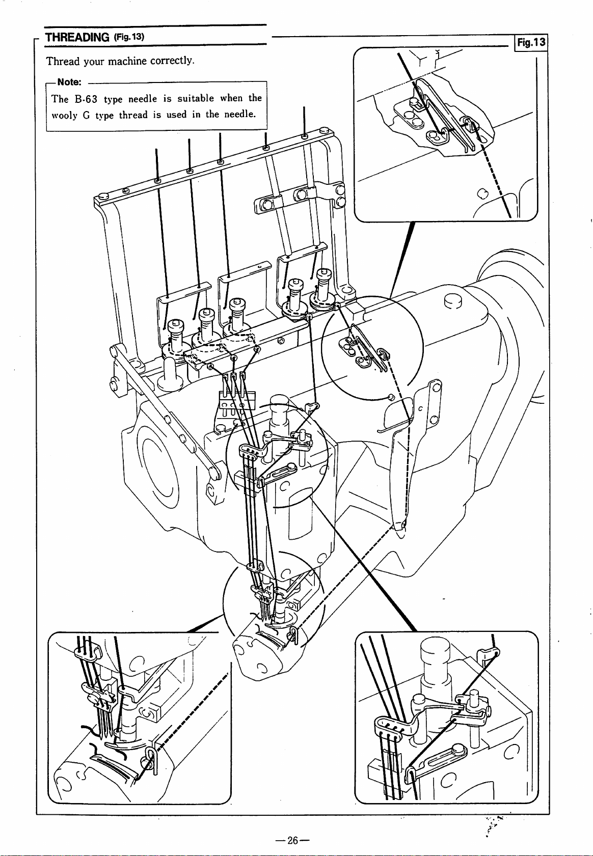
THREADING
(Fig.i3)
Thread
—
The
Note:
your
B-63
type
wooly G type
machine
correctly.
needle
thread
is
suitable
is
used
in
when
the
needle.
the
—
26
—
Page 28

REGULATING
THREAD
TENSION
(Fig.i4)
Adjust
O — ®
as
—Note:
NEEDLES
Use
Loosen
Insert
scarf
PRESSER
To
Adjusting
Adjust
making
results.
the
according
fabric,
Adjust
possible
balanced
the
thread,
each
while
sewing
needle
Screw © and
the
needle
to
the
adjust
the
Screw
the
sure
thread
(Fig.i5)
back
FOOT
pressure
tension
to
the
sewing
seam
width,
thread
system
tension
making
results.
UY128GAS.
replace
as
far
as
of
the
machine.
PRESSURE
pressure
of
©.
as
weak
positive
feeding
with
Tension
conditions
stitch
as
sure
the
it
will
go,
(Fig.l6)
the
presser
as
possible
and
length,
weak
neat,
needle.
facing
foot,
neat
sewing
Nuts
such
etc.
as
well
the
turn
while
A
Fig.16
STITCH
Remove
Link © up
LENGTH
Screw
or
Move © up
down
for a shorter
f—
Note:
When
making
needle
the
DIFF.
Move
diff.
•
•
•
guard
correct
FEED
Lever ® right
feed
ratio.
When © is
the
diff.
feed
To
gather
(4-^
1).
To
stretch
(5->
9).
CONTROL
©.
Loosen
down.
for a longer
stitch.
this
adjustment,
on
the
relationship
RATIO
set
at
the
ratio
the
fabric,
the
fabirc,
Screw @ and
stitch
main
feed
with
ADJUSTMENT
or
left
center
is
1:1.
move © to
move © to
(Fig.i7)
move
and
move
also
re-set
the
dog
and
keep
the
needle.
(Rg.i8)
and
adjust
between 4 and
the
left
the
right
©
the
5,
-27-
Page 29

MACHINE
ADJUSTMENTS
CYUNDER
When
that
Cylinder
needle
slot
of
the
center,
1.
Refer
2.
Turn
lowest
3.
Loosen
4.
Turn
the
Screws
DISASSEMBLING
If
it
is
and
re-adjust
in
sequence.
ADJUSTMENT
adjusting
should
the
to
Handwheel
point.
Screws
Eccentric
center
O.
necessary
the
(S)
is
in
pass
needle
adjust
Fig.
0
19
of
the
and
O,
each
machine
sewing
the
the
plate.
position
remove O —
to
0
Pin ® to
(Rgs.20-23)
to
disassemble
timings,
(Rg.i9)
parts,
correct
center
If
it
of
lower
the
set
needle
slot,
remove © to
make
position.
of
each
does
Cylinder
sure
Each
needle
not
pass
®.
©•
needle
each
needle
and
the
to
the
tighten
machine
to
©
^
Note:
Screws
numbers
to
them
with ^ marks
should'not
such a degree
are
ready
to
be
removed
that
the
be
removed.
on
the
parts
reference
but
loosened
secured
by
\
-28-
a
Page 30

NEEDLE
The
left
surface
point.
for
each
Make
machine.
To
adjust:
1.
Remove
2.
Turn
to
3.
Loosen
down,
—
Note:
In
even
NEEDLE
HEIGHT
needle
needle
height
point
when
the
Table 4 shows
machine
sure
that
the
the
head
the
handwheel
the
highest
Screw
and
adjusting
for
each
HEIGHT
Machine
FW601AC
FW603A
FW603AC
FW603AC
FW603AC
FW603ADX356
FW403AC
FW403A E X256
FW403A F x248
position.
obtain
the
needle.
(mm)
type
X240
A
x240
x240
X248
X356
X248
ADJUSTMENT
is
the
gap
and
the
needle
is
the
correct
type.
height
cover
(right).
and
move
the
the
correct
needle
height,
Fig.
(a)
needle
at
the
is
correct
raise
needle
height.
25.
Needle
(Rgs.24,25)
between
plate
upper
needle
for
the
needle
bar
set
gap
height
11.0
f/
❖
10.5mm
10.0mm
"
10.5mm
10,0mm
10.5mm
the
top
dead
height
your
bar
up
or
(b)
Table
(a)
mm
Fig.25
(a)
4
(b)
/A
/A
A\
LOOPER
The
To
1.
2.
#
3.
4.
5.
r—
AVOIDING
looper
adjust
Refer
Turn
to
avoiding
to
Fig.
the
handwheel
the
most
Insert a gauge
for
Bracket
Measure
Turn
®
to
Measure
gap
To
up
Note:
►
To
move
To
move
►
When
increase
position
the
handwheel
the
most
position
between
adjust,
or
down,
decrease
Link ® up.
increase
Link ® down.
using
the
(2.7mm).
MOTION
motion
26
and
protruded
or
vernier
(A)
retracted
(B).
(A)
and
loosen
Screw ® and
the
looper
the
looper
needles
gap
to
ADJUSTMENT(Ftgs.26-28)
is
2.7mm.
remove # —
and
bring
®.
Looper
Shaft
position.
calipers
of
the
and
bring
position
Make
(B)
is
thicker
more
3.0mm.
avoiding
avoiding
than
in
looper
shaft
Looper
(B).
sure
move
motion,
motion,
than
the
standard
the.
hole
tip.
Shaft
that
Link
#75,
the
®
1
1 i . 1
lllllllllllltllll
oitJ
0
_
0
-
2.6~2.7mm
(A) (B)
Fig.28
-29-
Page 31

LOOPER
HOLDER
AND
LOOPER
SETTING
(Rg.
29)
Fig.29
Attach
^
LOOPER
Turn
of
Adjust
To
Note:
When
its
tip
shaft.
the
the
gap
adjust,
Looper
tightening
looper
Holder O and
is
on
the
HEIGHT
handwheel
below
(a)
to
loosen
Looper
Screw
spot
0.3
Screw O and
0,
make
surface
ADJUSTMENT
and
bring
the
needle
—0.4mm.
of
the
highest
plate
turn
0.
sure
the
looper
(Fig.
Screw
that
30)
part
finger.
0.
Fig.30
OM
SYNCHRONIZING
TIMING
1.
Remove
2.
Turn
bar
Check
Turn
same.
be
To
©
Use
(Figs.
parts © — © in
the
handwheel
is
4.0mm
the
the
handwheel
In
both
in
the
same
adjust,
the
loosen
mark
31,32)
looper
on © as a guide
NEEDLE
sequence.
forward
up
from
the
lower
point
against
backward
cases,
level
against
the
looper
Screws 0 and
AND
LOOPER
until
the
dead
the
and
point
the
needle.
turn
Coupling
for
adjustment.
needle
point.
needle.
do
the
should
CBI
\
©
-30-
Page 32

ADJUSTING
NEEDLE
When
the
right
between
the
looper
dead
the
AND
looper
0 — 0.05mm,
looper
To
point
adjust,
loosen
CLEARANCE
LOOPER
passes
point
to
point
and
the
and
the
left
Screw ® and
BETWEEN
POINT
behind
the
left,
and
the
the
set
clearance
needle
to
(Rgs.33.34)
needles
the
clearance
right
needle
between
0.2 — 0.3mm.
turn
Screw
from
to
the
®.
ADJUSTING
NEEDLE
Table 5 shows
machine
correct
Check
centerline
is
To
looper
LOOPER
for
the
at
the
adjust,
right
SETTING
Machine
FW601ACX240
FW603AAX240
FW603AC
FW603AC
FW603AC
FW603ADX356
FW403AC
FW403A E X256
FW403A F X248
DISTANCE
AND
LOOPER
the
type.
your
Make
machine.
distance
and
the
right
dead
loosen
or
left.
type
X240
X248
X356
X248
BETWEEN
(ngs.34,35)
correct
(a)
looper
point.
distance
sure
that
between
the
point
when
Screw ® and
(a)
for
the
setting
right
needle
the
looper
move
Distance
6.8~7.0inin
❖
❖
6.4~6.6mm
6.0
—6.2niin
ff
6.4
—S.Smin
6.0
—6.2niin
6.4
—6.6nim
each
is
the
Table
(a)
r
V
1
5
h-O-
/'
0.3mm
0.05mm
Fig.35
CHECKING
BETWEEN
Make
between
1.
•
2.
•
3.
•
•
•
sure
needle
Turn
from
behind
the
If
Turn
from
If
from
the
the
the
Make
sure
top
not,
re-adjust
the
the
behind
Make
point
Turn
the
sure
and
not,
re-adjust.
the
the
point
touches
The
looper
the
needle
The
needle
thickness.
If
not,
re-adjust
THE
NEEDLE
again
and
handwheel
right
left
needle
that
the
of
the
needle
handwheel
right
left
needle
that
the
needle
handwheel
left
to
the
eye
centerline.
point
RELATIONSHIP
AND
LOOPER
the
correct
looper.
and
move
to
the
left
until
centerline.
point
is
0.8—1.0mm
eye.
the
distance
to
the
the
gap
is
the
right
back
center
is
1/3
the
looper
(a).
and
move
left
until
centerline.
between
0.2 — 0.3mm.
and
move
until
of
the
looper.
is
3.0 — 3.5mm
of
the
avoiding
(Rg
36)
relationship
the
looper
its
point
is
above
the
looper
its
point
is
the
looper
the
looper
the
left
needle
from
looper
blade
motion.
0.8-
1.0mm
J
(a)
I i
0.2-
/
0.3mm
1
3.0 ~ 3.5
Fig.36
mm
-31-
Page 33
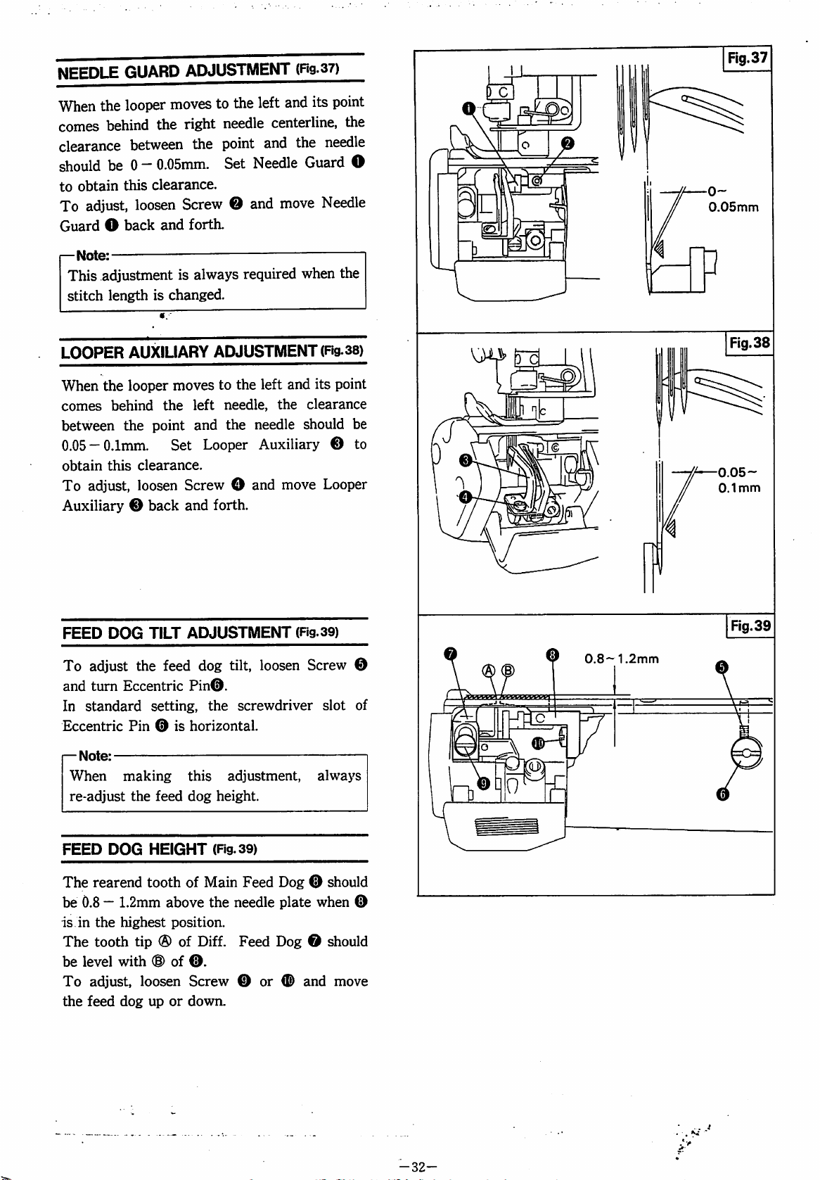
NEEDLE
When
comes
clearance
should
to
obtain
To
Guard O back
(—
Note:
This
stitch
GUARD
the
looper
behind
between
be 0 -
this
adjust,
loosen
—
adjustment
length
ADJUSTMENT
moves
the
to
right
the
0.05mm.
clearance.
Screw @ and
and
forth.
is
always
is
changed.
the
left
needle
point
Set
centerline,
and
Needle
required
(Rg-37)
and
its
the
needle
Guard
move
Needle
when
Fig.37
point
the
O
0-
0.05mm
the
LOOPER
When
comes
between
0.05
obtain
To
Auxiliary ® back
FEED
To
and
In
standard
Eccentric
—
Note:
When
re-adjust
AUXILIARY
the
looper
behind
the
—0.1mm.
this
clearance.
adjust,
adjust
turn
loosen
DOG
TILT
the
Eccentric
setting,
Pin ® is
making
the
moves
the
point
Set
feed
feed
ADJUSTMENT
to
the
left
left
needle,
and
the
Looper
the
needle
Auxiliary ® to
Screw O and
and
forth.
ADJUSTMENT
dog
tilt,
loosen
Pin®.
the
screwdriver
horizontal.
this
adjustment,
dog
height.
(Fig.
and
its
clearance
should
move
(Fig.39)
Screw
always
38)
point
be
Looper
©
slot
of
(^31
®
0.8-1.2mm
0.05-
0.1mm
Fig.39
FEED
The
be
is
The
be
To
the
DOG
HEIGHT
rearend
0.8 — 1.2mm
in
the
tooth
level
adjust,
feed
tooth
highest
tip ® of
with
(S)
loosen
dog
up
(Fig.39)
of
Main
Feed
Dog ® should
above
the
needle
position.
Diff.
of
®.
Screw ® or ® and
or
down.
plate
Feed
Dog ® should
when
move
®
-32-
Page 34

NEEDLE
Set
and
1.
(D = 18.0mm
2. ® =
3. ® =
—
Set
needle
the
thread
each
the
eyelet
19.0mm
20.0mm
Note:
each
thread
looper.
to
THREAD
distance
Thread
be
used.
GUIDE
between
of
(D,
(the
(the
(the
can
Adjust
ADJUSTMENT
the
®
as
left
needle
center
right
Guide 0 ® ® so
be
needle
needle
smoothly
this
according
bracket
follows.
thread)
thread)
thread)
that
cast
off
(Fig.
40)
surface
the
from
to
the
NEEDLE
THREAD
ADJUSTMENT
Set
Needle
it
lightly
To
adjust,
r—
Note:
When
foot
turned
loop
the
needle.
this.
NEEDLE
Thread
contacts
loosen
the
fabric
on
the
way
backward.
tends
to
Spring ® functions
THREAD
ADJUSTMENT
Set
each
upper
2.3mm
Bar
the
lowest
To
adjust,
Thread
above
Thread
Guide ® when
position.
loosen
Supports ® up
PRESSER
(Fig.4i)
Presser
Screw
®.
Screw 0 and
is
removed
of
sewing,
In
such
be
formed
on
SUPPORT
(Fig.42)
face
of
Needle
the
eyelet
Screws 0 and
or
down.
SPRING
Spring ® so
turn
Knob
from
the
presser
the
handwheel
case, a thread
the
front
side
to
prevent
Thread
center
the
Supports
of
needle
bar
move
that
®.
is
of
Needle
is
in
Needle
/
I I I I ir
2.3mnn
Fig.41
—
Note:
Needle
improve
having
also
when
As
needle
the
Thread
tightening
been
to
assist
the
each
Support 0 can
thread,
type
of
Support ® functions
released
to
produce a good
looper
make
the
thread
catches
each
needle
from
the
the
needle
be
adjusted
adjustment
used.
to
thread
looper,
shaped
after
and
loop
thread.
for
each
according
to
-33-
teiete^
Page 35
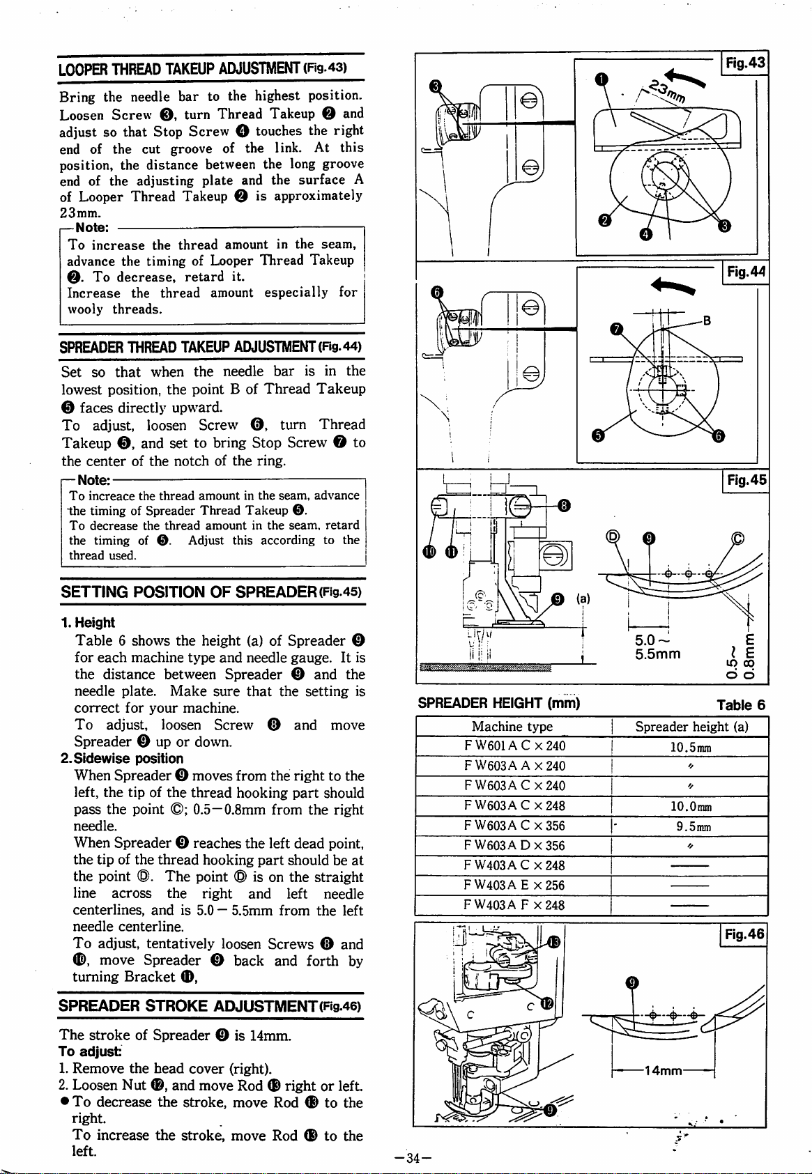
LOOPER
THREAD
TAKEUP
ADJUSTMENT
(Rg.43)
Bring
Loosen
adjust
end
position,
end
of
23mm.
—Note:
SPREADER
Set
lowest
the
the
Screw
so
of
the
the
of
the
Looper
To
increase
advance
©.
Increase
wooly
©
To
Takeup
—
Note:
To
the
To
the
thread
the
To
decrease,
threads.
so
that
position,
faces
directly
adjust,
©,
center
increace
timing
decrease
timing
used.
needle
that
Thread
the
THREAD
of
of
bar
to
©,
turn
Stop
Screw O touches
cut
groove
distance
adjusting
between
plate
Takeup © is
the
thread
timing
of
Looper Thread
retard
thread
when
the
amount
TAKEUP
the
point B of
upward.
loosen
and
the
the
Spreader
the
of
set
notch
thread
thread
©.
Adjust
Screw
to
bring
amount
Thread
amount
the
highest
Thread
of
Takeup @ and
the
the
and
amount
it.
especially
ADJUSTMENT
needle
Thread
©,
Stop
of
the
ring.
in
the
Takeup
in
the
this
according
position.
the
right
link.
At
this
long
groove
the
surface
A
approximately
in
the
seam,
Takeup
for
(Rg.
44)
bar
is
in
the
Takeup
turn
Thread
Screw © to
seam,
advance
©.
seam,
retard
to
the
SETTING
1.
Height
POSITION
Table 6 shows
for
each
machine
the
distance
needle
correct
To
plate.
for
adjust,
Spreader © up
2.Sldewlse
When
left,
pass
needle.
When
the
the
line
centerlines,
needle
To
©,
turning
position
Spreader © moves
the
tip
the
point
Spreader © reaches
tip
of
the
point
®.
across
centerline.
adjust,
move
Spreader © back
Bracket
OF
the
height
type
and
between
Make
your
loosen
or
of
the
©;
thread
The
the
and
is
tentatively
Spreader © and
sure
machine.
Screw
down.
thread
0.5—0.8mm
hooking
point ® is
right
5.0 — 5.5mm
loosen
©,
SPREADER
(a)
of
Spreader
needle
that
gauge.
the
©
from
the
hooking
from
the
left
part
should
on
the
and
left
from
Screws © and
and
(Fig.45)
setting
and
move
right
to
part
should
the
right
dead
point,
be
straight
needle
the
forth
©
It
is
the
is
the
at
left
by
SPREADER
Machine
FW601AC
FW603A A X240
FW603AC
FW603AC
FW603A C X356
FW603ADX356
FW403AC
FW403A E X256
FW403A F X248
HEIGHT
type
X240
X240
X248
X248
(mm)
5.0-
5.5mm
Spreader
lO.Smm
lO.Otnm
9.5nmi
lO
Table
height
(a)
00
6
SPREADER
The
stroke
To
adjust:
1.
Remove
2.
Loosen
•
To
decrease
right.
To
increase
left.
STROKE
of
Spreader © is
the
head
Nut
®,
and
the
stroke,
the
stroke,
ADJUSTMENT(Rg.46)
14mm.
cover
(right).
move
Rod ® right
move
Rod ® to
move
Rod ® to
or
left.
the
the
-34-
14mm
Page 36

SPREADER
THREAD
GUIDE
ADJUSTMENT
(Rg.
47)
Adjust
1.
2.
Turn
to
the
Set
the
in
the
the
right
centerline
Guide © to
To
adjust,
©
back
and
3.
Set
the
gap
©
to
0.5 — 1.0mm.
To
adjust,
©
up
or
down.
4.
Set
the
centerline
Guide © to
To
adjust,
Bracket
SETTING
THREAD
Set
Guide © and
To
adjust,
up
or
I—
Note:
To
lower
To
raise
©.
POSITION
GUIDE
the
distance
loosen
down.
increase
Guide
decrease
Guide
following
handwheel
dead
point.
distance
and
3.0 — 4.0mm.
loosen
forth.
between
the
Screw © and
between
loosen
distance
and
Screw © and
between
the
6.7 — 7.0mm.
loosen
(Fig.48)
between
the
bracket
Screw © and
the
thread
©.
the
thread
©.
manner.
and
bring
Spreader
the
needle
eye
center
of
move
Spreader © and
move
the
needle
eye
center
Screw
OF
SPREADER
Spreader
to
2.4mm.
amount
amount
of
©
and
move
in
the
in
the
Thread
Thread
Guide
©
bar
Thread
Guide
Guide
Guide
bar
move
©
seam,
seam,
2.4mm
3.0-4.0mm
i
rs
0.5—1.0mm
6.7--7.0mm
SETTING
THREAD
Set
Guide
right
To
adjust,
Plate
—
Note:
The
up
can
Guide
SETTING
THREAD
Set
Eyelets © and © at
To
adjust,
Eyelets © and
Note:
To
shift
To
decrease
shift
POSITION
GUIDE
Plate © to
ends
aligned.
loosen
©.
—
timing
for
be
changed
Plate
POSITION
©.
EYELETS
loosen
®.
increase
Eyelets © ©
Eyelets © ©
the
the
the
OF
LOOPER
PLATE
(Fig.
49)
Bracket © with
Screws © and
looper
by
thread
shifting
OF
the
LOOPER
(Fig.49)
the
right
Screws © and
thread
thread
to
to
amount
the
amount
the
right.
left.
shift
Guide
to
be
taken
position
extremes.
©,
and
in
the
seam,
in
the
seam,
their
of
shift
-35-
Page 37

THREAD
When
foot
simultaneously
tension.
To
Releasing
I—
Note:
When
releasing
a
tension
RELEASE
the
presser
lift
pedal,
adjust,
loosen
Shaft
the
the
is
applied
work
©.
presser
foot
ADJUSTMENT
foot
is
raised
the
thread
to
relax
Screw O and
foot
is
lift
pedal,
to
each
make
thread.
(Rg
by
pressing
release
each
turn
should
thread
Thread
lowered
sure
SO)
the
by
that
PRESSER
When
the
and
To
adjust'
1.
Turn
to
2.
Make
3.
Leave a clearance
Link 0 and
To
©
—
Note:
If
there
O,
BAR
GUIDE
the
presser
needle
Screw O to
the
the
plate,
the
hand
lowest
sure
adjust,
up
or
is
loosen
down.
no
presser
that
Screw
gap
position.
foot
ADJUSTMENT
foot
is
lowered
set
the
gap
between
0.5 — l.Omm.
wheel
and
bring
the
Lever 0 contacts
of
0.5 — l.Omm
O.
Screw O and
between
may
Link 0 and
not
be
fully
(Fig.5i)
and
sits
Link
feed
Screw
between
move
Guide
Screw
lowered.
on
®
dog
0.
0.5—
l.Omm
-36-
Page 38

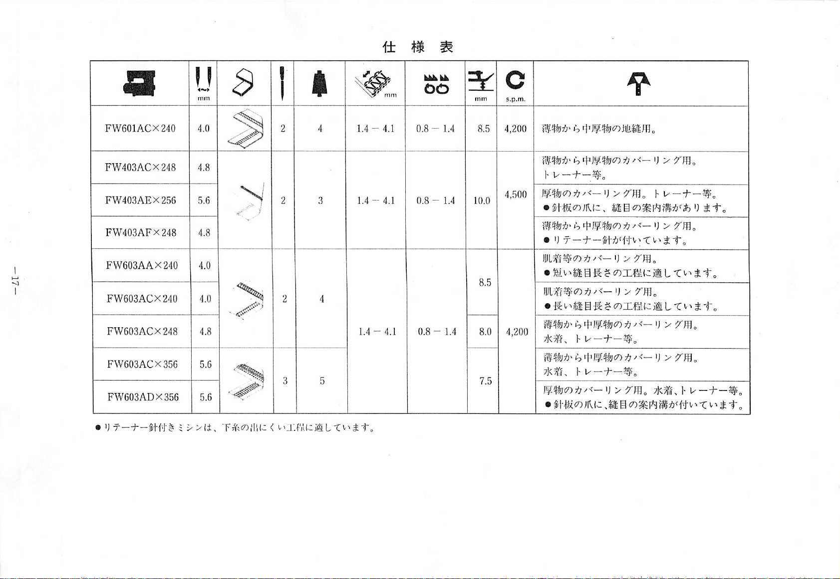
SPECIFICATIONS
FW601ACX240
FW403ACX248
FW403AEX256
FW403AFX248
FW603AAX240
FW603ACX240
FW603ACX248
FW603ACX356
FW603ADX356
1.4-4.1
1.4 - 4.1
0.8-
1.4
0.8-
1.4
0.8 - 1.4
10.0
8.0
4,500
4,200
Seaming
Cover
on
stitching
Sportswear,
Cover
stitching
•
The
needle
Cover
stitching
•
With a retainer
Cover
stitching
•
Suitable
Cover
•
Suitable
Cover
Swim
Cover
Swim
Cover
Swim
•
The
for
stitching
for
stitching
suits,
stitching
suits,
stitching
suits,
needle
light
to
medium
on
light
to
etc.
on
heavy
fabrics.
plate
has a seam
on
light
to
needle.
on
underwear.
short
stitch
on
underwear.
long
stitch
on
light
to
sportswear,
on
sportswear,
on
sportswear,
plate
etc.
light
to
etc.
heavy
etc.
has a seam
fabrics.
medium
Sportswear,
guiding
medium
length
length
operations.
operations.
medium
medium
fabrics.
guiding
fabrics.
etc.
groove.
fabrics.
fabrics.
fabrics.
groove.
The
machine
fitted
with a retainer
needle
is
good
for
operations
where
the
looper
thread
is
difficult
to
be
fed.
Page 39

MEMO
-38-
Page 40
FW
Series
OPERATORS
MANUAL
'
^
jj
THREADING
■if-
thread
REPLACING
STITCH
DIfIeREKiTIAL
presser
silicone
LUHRICATION
m
cleaning
L
w
^
tension
CO
^
41^
The
length
X CO g ti
foot
o/l
}[»
1^
for
NEEDLE'
CON'i'KUL
EEED
pressure
the
g
CONTENTS
cont
kui.
hk
device
<k
^
d
^
®
7
^
Page 41
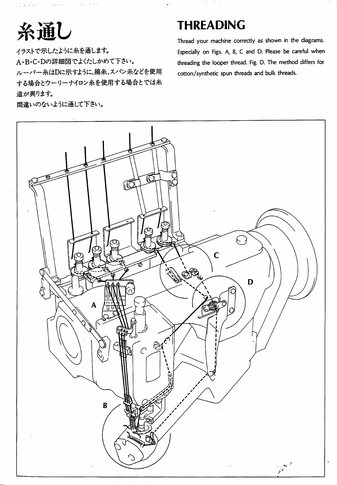
THREADING
A • B-C-D«r)gfMll
ilA^MOSto
T-j:
(cii
L"tT?v
<^cL;!>>a6rT§i'
V
Thread
Especially
threading
cotton/synthetic
your
machine
on
Figs.
the
looper
correctly
A,
B, C and
thread.
spun
threads
as
shown
D.
Please
Fig.
D.
and
bulk
The
method
threads.
in
the
diagrams.
be
careful
differs
when
for
H
Page 42

w
B
Bulk
threads
Cotton/synthetic
spun
threads
Page 43
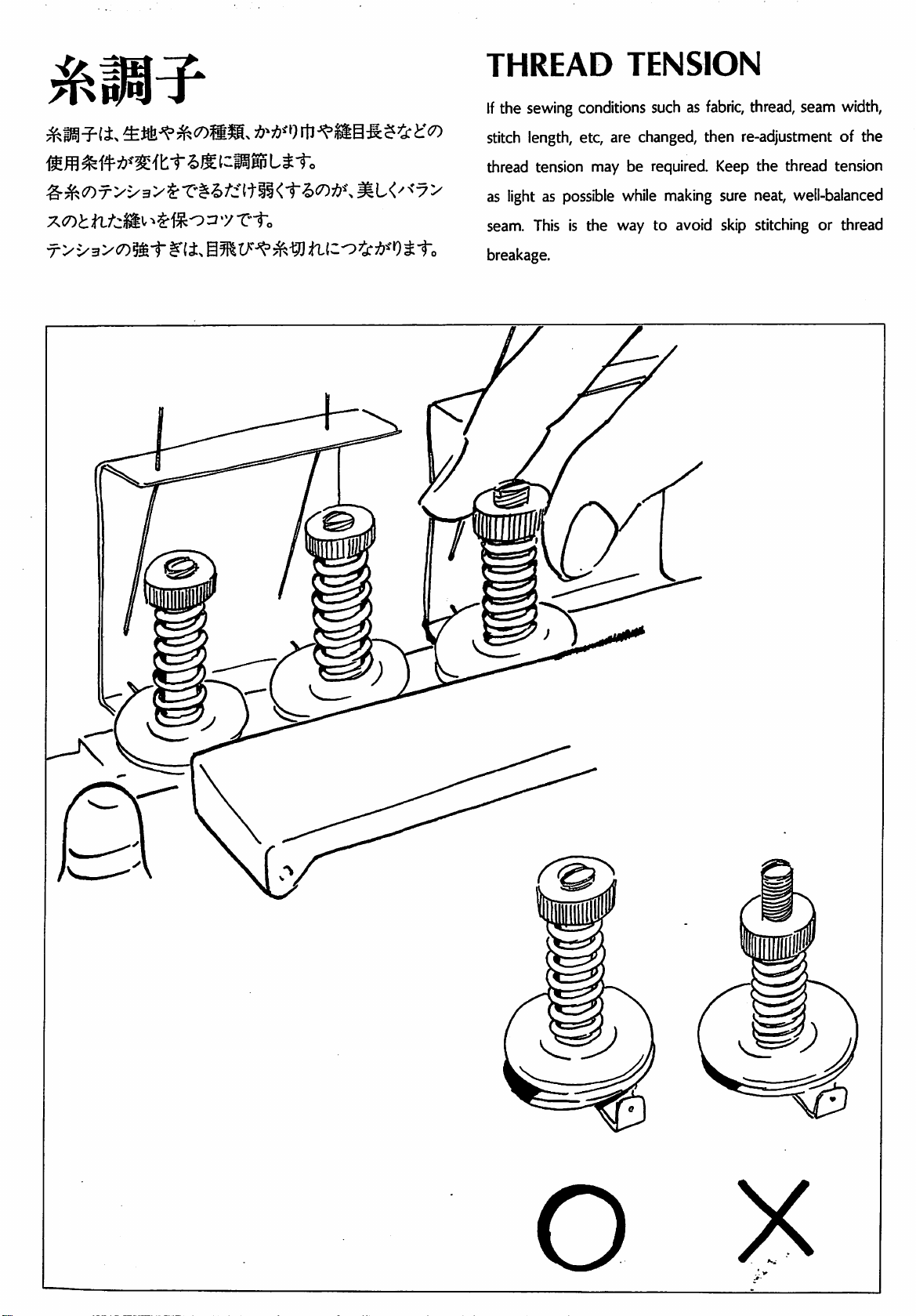
THREAD
If
the
sewing
stitch
length,
conditions
etc,
TENSION
such
as
are
changed,
fabric,
thread,
then
re-adjustment
seam
of
width,
the
^^OT>X3>$-"C^I>/ittll<1"l)W,^L<'^*-7>
^$1So3'y
T-f.
thread
as
seam.
breakage.
tension
light
as
This
may
be
possible
is
the
while
way
required
making
to
Keep
sure
avoid
skip
the
thread
neat,
stitching
tension
well-balanced
or
thread
Page 44

REPLACING
THE
NEEDLE
f>-fe-y
K7^/
<-
(iTtwili
S-f#f«|S]§$-5i75'AiU9o
ffi
ffl
«ti4UY128GASS-fi6uito
x-mncm
Ky^-'<-S-1s6o
LiiAr-TSi-
>0
Holding
the
tightening
into
tion
The
the
screw
the
of
needle
with
the
hole
the
damaged
of
needle.
system
o
needle
the
alien
screw,
the
screw.
Is
is
it
insert
UY128GAS.
with a pair
key
driver.
the
tip
Please
inserted
make
fully
of
tweezers,
When
of
the
alien
sure
into
the
loosen
loosening
of
the
needle
key
direc
hole
or
fully
?
Page 45

STITCH
CONTROL
LENGTH
T-,
T^}boT~F$*''*o
«:Sr#.
WAtcft®
tt
Wp®
$"£'T
Remove
ing
L
down
Please
to
to
the
link.
Move
for a shorter
note
that
re-set
the
do
this.
cap-screw.
the
after
needle
Loosen
link
up
stitch.
this
guard.
the
screw
for a longer
adjustment,
So,
please
stitch
it
will
ask
of
the
and
be
your
connect
move
it
necessary
mechanic
Page 46

/"c
tt
T-
T-#
DIFFERENTIAL
CONTROL
Differential
is
turn
If
you
feed
the
lever
turn
the
control
to
the
right
lever
to
is
very
the
left,
or
to
FEED
easy.
the
then
All
you
left.
you
have
can
gather
to
do
the
fabric.
stretch
If
the
you
fabric.
turn
the
lever
to
the
right,
then
you
can
Page 47

PRESSER
Turn
the
Keep
it
thumb
as
screw
light
as
FOOT
and
adjust
possible
while
PRESSURE
the
presser
making
foot
sure a neat,
pressure.
well-
riil;TSvv
balanced
seam.
Page 48
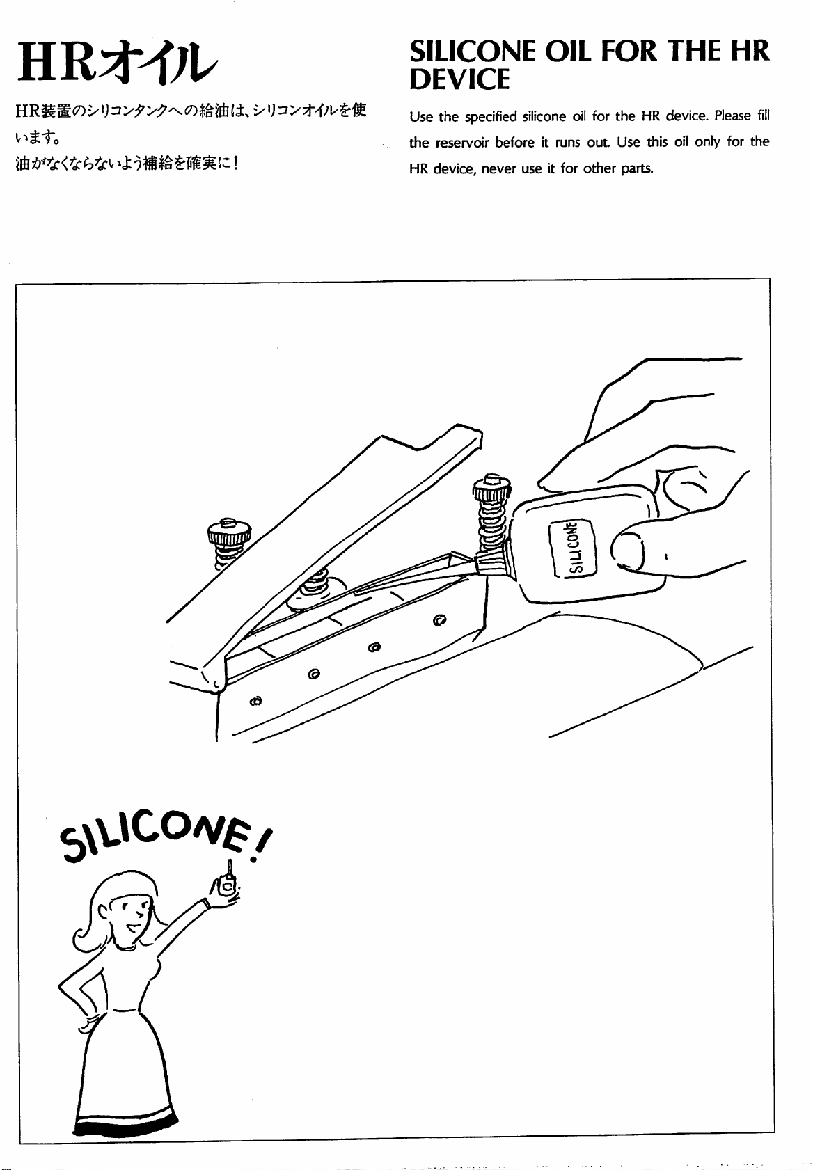
SILICONE
DEVICE
Use
the
specified
the
reservoir
HR
device,
before
never
use
OIL
siiicone
it
runs
it
for
oil
for
out
other
FOR
the
HR
Use
parts.
THE
device.
this
oil
Please
only
for
MR
fill
the
HUllIlf/lii
Page 49

LUBRICATION
bXl^W
There
screw
the
add
The
are
and
upper
oil
recommended
the
spreader
TWO
fill
the
line
of
before
the
drive
inlets
for
machine
the
oil
oil
level
level
oil
is
with
mechanism
iubricatton.
oil
sight
goes
of
VC46.
until
the
gauges.
below
by
hand.
Take
the
Oil
out
the
oil
level
reaches
Remember
lower
line.
each
link
cap-
to
of
|i*-^
31
Page 50
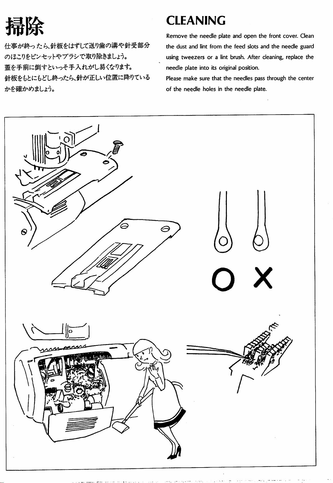
CLEANING
cotSCO^tV-fe-yh^ryvT-Sl'J^I^SLi-),
Remove
the
dust
using
tweezers
needle
Please
of
the
plate
make
needle
the
and
needle
lint
from
or a lint
into
its
sure
that
holes
in
plate
and
open
the
feed
brush.
original
the
needles
the
needle
position.
the
slots
and
After
cleaning,
pass
plate.
front
cover.
the
needle
replace
through
the
Clean
guard
the
center
S)
Page 51

F
W
6
O O
•
F
W
4
O
O
^ i/ y (0
FW603CB X 240
FWe03CB X 248
FW803CB X 256
FW803CB X 358
FW803CB X 384
FW403CB X 240
FW403CB X 248
FW403CB X 258
FW403CB X 356
FW403CB X 364
^
$ -y y (D M ii:.
FW603CB X 240
FW803CB X 248
FW603CB X 258
FW803CB X 356
FW803CB X 364
FW403CB X 240
FW403CB X 248
FW403CB X 256
FW403CB X 358
FW403CB X 364
(aa)
^
FW803CC X 240
FW803CC X 248
FW603CC X 256
FW403CC X 240
FW403CC X 248
FW403CC X 256
(offl)
FW803CC. X 240
FW803CC X 248
Ftf603CC X 256
FW403CC X 240
FW403CC X 248
FW403CC X 256
FW6 0 0»
8.0
7.5
7.0
//
//
10.0
n
ft
ft
ft
11.5
11
10.5
10.5
10
11.5
11
10.5
10.5
10
FW4 0 0 y —
1
(a)
FW803CB X 240
FW803C6 X 248
FW603CB X 256
FW803CB X 356
FW803CB X 364
F»403CB X 240
FW403CB X 248
FW403CB X 258
FW403CB X 358
FW403CB X 384
^
3
(a)
FW803CB X 240
FW803CB X 248
FW603CB X 258
FW603CB X 356
FW603CB X 364
FW403CB X 240
FW403CB X 248
FW403CB X 256
FW403CB X 356
FW403CB X 384
^
A
y
y
5 y y
<o
F«803CC X 240
FW603CC X 248
FW803CC X 256
FW403CC X 240
FW403CC X 248
mOZCC
0?I1:
(as)
(D
5^
^
FW603CC X 240
FW603CC X 248
FW803CC X 258
Ftf403CC X 240
FW403CC X 248
FW403CC X 258
X
258
4,500
ft
ft
ft
ft
ft
ft
ft
6
5.6
5.2
5.2
4.8
6
5.6
5.2
5.2
4.8
^4
(a)
-6.5
-6.1
-5.7
-5.7
-5.3
—8.5
-6.1
-5.7
-5.7
-5.3
y
'
$
FW603CB X 240
FW603CB X 248
FWe03CB X 256
FW603CB X 356
FW603CB X 364
FW403CB X 240
FW403CB X 248
FW403CB X 256
FW403CB X 356
FW403CB X 364
y
(m)
(D
^
FW603CC X 240
FW803CC X 248
FW603CC X 256
FW403CC X 240
FW403CC X 248
FW403CC X 256
Sliy^yo^^^
10.5
10.3
8.5
3.5
9.2
m
(a)
5
-50-
Page 52
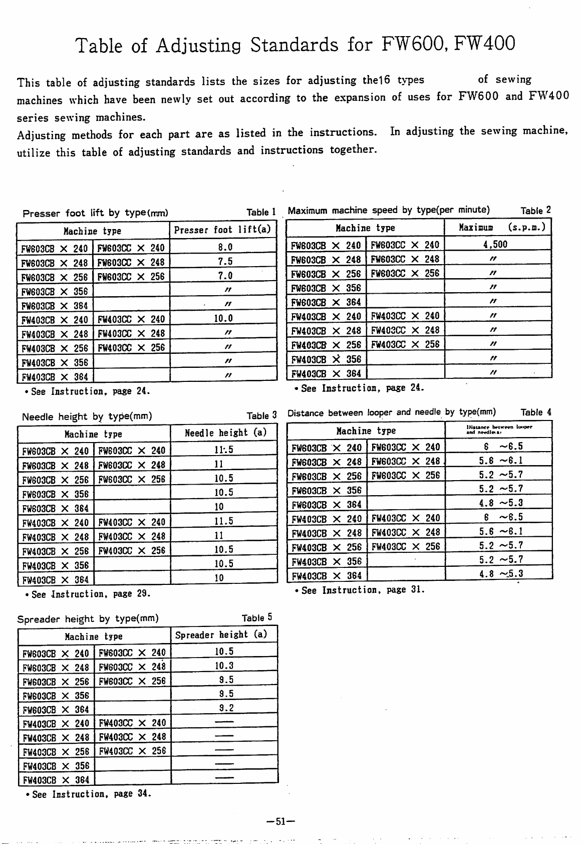
This
table
Table
of
adjusting
of
Adjusting
standards
lists
the
Standards
sizes
for
adjusting
for
FW600,
thel6
types
FW400
of
sewing
machines
series
Adjusting
utilize
Presser
FweoacB X 240
FW803CB X 248
FW803CB X 258
FW803CB X 356
FW803CB X 384
Ftf403CB X 240
FW403CB X 248
FW403CB X 258
FW4a3CB X 358
FW403CB X 384
•See
which
sewing
have
machines.
methods
this
table
foot
lift
Hachine
Instruction,
type
FW803(X: X 240
FW803(3) X 248
Ftf603CC X 258
FW403CC X 240
FW403CC X 248
FW403CC X 258
been
newly
for
each
of
adjusting
by
type
(mm)
page
24.
set
out
part
are
as
standards
Presser
foot
8.0
7.5
7.0
n
ft
10.0
//
//
ft
ft
according
listed
and
instructions
in
the
to
instructions.
Table 1 Maximum
lift(a)
FWe03CB X 240
FtfG03CB X 248
FW603CB X 258
FW803CB X 358
FW803CB X 384
FW403CB X 240
FW403CB X 248
FW403CB X 258
FW403CB X 358
FW403(S X 384
•See
the
expansion
together.
machine
Machine
Instruction,
of
uses
In
adjusting
speed
FW803CC X 240
FW803CC X 248
FW803CC X 258
FW403CC X 240
FW403CC X 248
FW403CC X 258
type
page
by
type(per
24.
for
FW600
the
minute)
MazimuiD
and
FW400
sewing
machine,
Table
(s.p.m.)
4,500
ft
ft
ft
ft
ft
ft
ft
ft
2
Needle
FW803CB X 240
FW603CB X 248
FW803CB X 258
FW803CB X 358
FW803CB X 384
FW403CB X 240
FW403CB X 248
FW403CB X 258
FW403CB X 358
FW403CB X 384
•
Spreader
FW803CB X 240
FW803CB X 248
FW803CB X 258
FW803CB X 358
FW803CB X 384
FW403CB X 240
FW403CB X 248
FW403CB X 258
FW403CB X 358
FW403CB X 384
•See
height
Machine
See
Instruction,
height
Machine
Instruction,
by
type(mm)
type
FW803CC X 240
FW803CC X 248
FW803CC X 258
Ftf403CC X 240
FW403(X) X 248
FW403CC X 256
page
29.
by
type(mm)
type
FW803CC X 240
FWeOOCC X 248
FW803(X: X 256
FW403(X) X 240
Ftf403CC X 248
FW403CC X 258
page
34.
Needle
Spreader
height
lh5
11
10.5
10.5
10
11.5
11
10.5
10.5
10
height
10.5
10.3
9.5
9.5
9.2
Table
(a)
Table
(a)
Distance
3
FW603CB X 240
FW803CB X 248
FW803CB X 256
FW803CB X 358
FW803CB X 364
FW403CB X 240
FW403CB X 248
FW403CB X 256
FW403CB X 358
FW403CB X 364
•See
5
between
Hachine
Instruction,
looper
type
FW803CC X 240
FW803CC X 248,
FW803CC X 258
FW403CC X 240
FW403CC X 248
FW403CC X 258
and
page
needle
31.
by
typ€(mm)
llisiAnce
and
nevdlc^a*
5.8
5.2
5.2
4.8
5.8
5.2
5.2
4.8
8
8
briwem
-8.5
-8.1
-5.7
-5.7
-5.3
—8.5
-8.1
-5.7
-5.7
-5.3
Table
lo«»per
4
-51-
Page 53
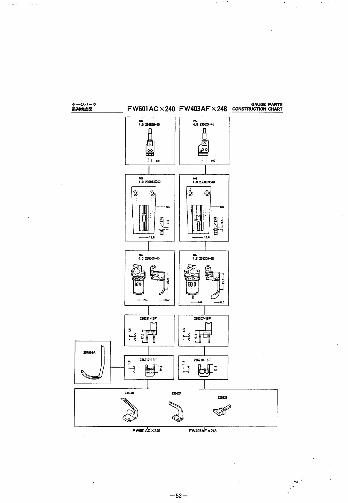
FW601ACX240
FW403AFX248
coNSTRiSrnw
NG
4.0
NG
4.0
4.0
236625-40
oo
—i-i—
236013C40
236306-40
NG
4.8
236627-48
[rflO
——
NG
4.8
(o;
4.8
!3
094
NG
236007C48
(Q)
238305-48
207936A
236501
FW601ACX240
236212-16F
8.0
Sr
236207-1SF
FW403AFX248
-52-
Page 54

MACHINE
T — A • '<
BED
-y
FRAME
K
202045
230059-91
PARTS
CATALOG
FW600
FW400
First
edition
High
speed,
(issued
in
2-
December,
>j
With
()n
or
1984}
>J
Without
3-needie
December,
cover
interlock
KS
(1984^12^1^)?)
thread)
cover
thread)
machines
1984
206942
230050-FD
230053-
230055
206705
230056
rV-
230057
-230004
Ul I 230018
202047
20217S
OL-'
230016
230019
230021
230013
5556
230018
230058
230052-FD
234514
5091
230014
0051-FD
234515^^
233036
230027
202287
A
230042
234043
230019
5138B
230047
210679
230021
230030
210879
212279
5461
230028
^PEGASUS
230003
230054
234593
233036
202405
230045
/
230043
230553-^
5584
y
230026
230033
208272
208272
230032
A91
Page 55
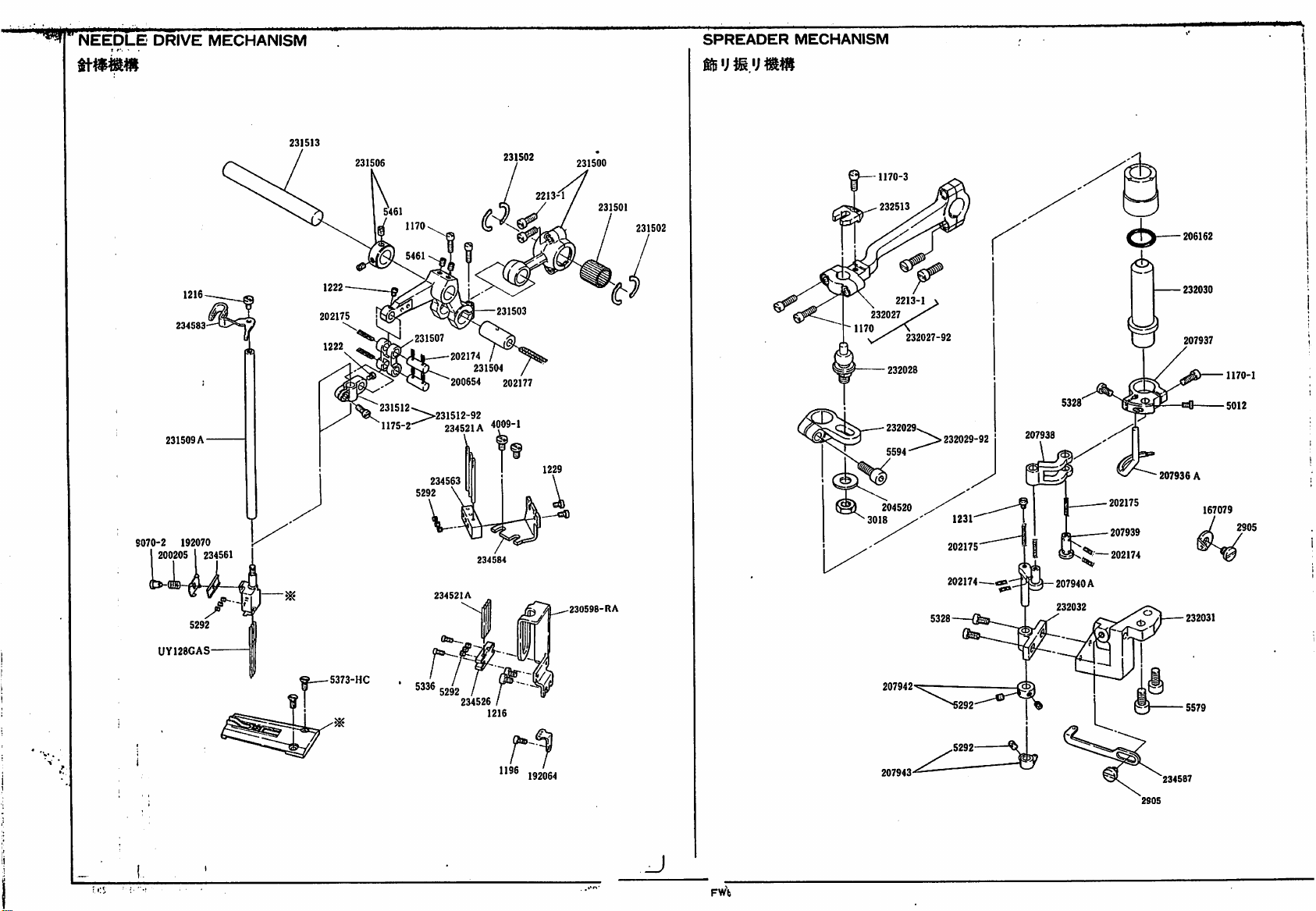
NEEDLE
DRIVE
MECHANISM
SPREADER
MECHANISM
9070-2
234S83
231509
192070
231513
231506
202175
231507
202174
200654
"231512-^
^>231512-92
A-
"1175-2
234521A
234563
234521A
231504
234584
i
231502
231503
202177
4009-1
2213-1
^
231500
-
230598-R
231501
A
231502
1170-3
232513
232027
204520
3018
2213-1
232028
232029
232027-92
232029-92
1231
202175
202174
207938
207940
232032
206162
232030
207937
1170-1
207936
A
202175
207939
—
202174
A
167079
2905
232031
UY128CAS
5373-HC
' 5336
234526
1196
192064
FWb
207942
207943
234587
2905
Page 56
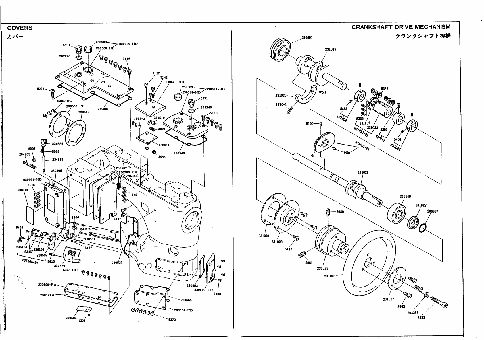
COVERS
240091
CRANKSHAFT
DRIVE
MECHANISM
204905
208724
230564-HD
5118
5484-HC
230562-FD
t
234585
234586
230565
230563
230560-HD
230561
230567>
5142
1998-2 I 230510
230511
^
3044
230S46-HD
230549
230503
230548-HU
202240
231020
1170-1
231019
231007
231021
231033
240140
231022
206837
230530
230531
236104
,236103
230597
230590-R
230527
5613
230570
A
A
5328-HC
230520
2305S4-FD
230552
230550
/
231024
231023
231025
231026
231027
204293
5522
Page 57

l_UUHfc.K
UKlVt
234588
234545
234530
234589
137906
1231
234544
234542B
5364
232509
gjj20
232510
232010
232512
1170-1
232513
1170-1
202175
202174
232009
232520
2918
232511
232504
232508
2213-1
232503
232505
1435
232506
232523-92
240165
236628
5614
233009
233008
5461
^3^4
^
5183
234066
233006
233006
233011
233011
5571
5571
202174
233000
233005
233007
233014
233003
1170-1
208245
>233001
233002-92
232511
233041-91
233020
233037
A
—
232513
I
A
233015
236624
236501
232522
232521
232517
\
5568-
232518
232519
232515
232502
232516
232514
233033
204185
233039
233012
233040
5147
5461
233020
233042
233019
233032
2"''"
^
233033
233011
.g35j
Page 58

Page 59
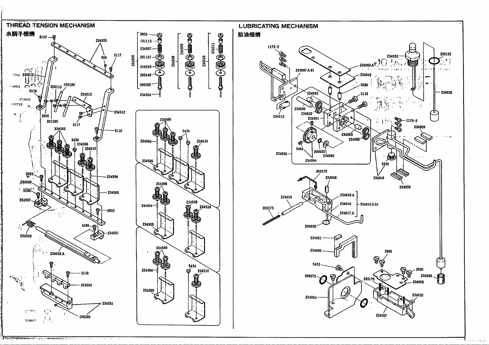
THREAD.
TENSION
MECHANISM
LUBRICATING
MECHANISM
nr,'
234512"
uiof.s
s
1234500
234557
5116
/720611S
2905
201185
234506
"2120
5434
234513
234508
234510
234555
234504
234505
5117
234512
5116
101113
234507
201157
210319
208449
306306
234504
234504
234505
234504
234506
234508
234510
234510
1175-2
202175
234012
234000
234019
—
206162
234038
234033
234007A
91
234042
^5580'
234062Ar.)V.* , t
234003
234006
234002
234001
234003
234004
200020\
234005
202176
234068
234016
234018
234017A
—
5118
234002
A
-234015 A 91
1-^^-.
..
■'
234049
.M-,
„
7:,
fe •••'
234059
?
1175-2
234059
234505
234503
^
234502A
234554
198205
A"
■.
Aniw*
234501
234551
234504H
234505
234506
@ 234510
200030
234061
234060
208272
234054
^
202175
234057
234026
234058
234032
Page 60

412
485
484
178
ACCESSORIES
286
285
.284
283
FW603-403CC
FW603-403DC
4.0
23S627-40
4.8
236627-48
CONSTRUCTION
Jjo]
Lfij
—
NQ
GAUGE
na
5.6
PARTS
236627-56
CHART
322
200
UY128GAS
131
NO
4.0
4.8
236028C40
236022C48
4.0
4.8
23G02SC40
236026C48
NO
S.6
236023C56
NO
6.6
236026066
N
T
%
5.6
257314-56
238223-16F
235009
235083-FD
205473
4.0
4.8
236222-16F
236313-40
236313-48
4009-1
235086
235085
235084-RA
207351
4908-44
202922
207353
202924
.207352
207354
202577
207936A
FW603DCX240'248
FW603CCX
236224-16F
240*248
236501
FW403DCX240'1!48
FW403CCX
2S6224AI6r
240*248
U'-
236624
238225-I6F
FW403CC
236628
h
SOX
256
FW403DCX256
\.
I
236225AI6F
207936A
FW603CCX25(
FW603DCX256
Page 61

MdiriiMUHii
Jo]
. « ' NA
GAUGE
FW603-403CB
J
^
ItJjX
>
-NO
NQ
5.6
236827-58
NO
4.0
238827-40
4.8
236827-48
-NO
CONSTRUCTION
O
u
s
-
PARTS
CHART
ij
L/l'
-NO
-1-
NG
4.0
4.8
236827-40
238627-48
NO
5.6
238831-58
8.4
238831-64
-NO
FW603*40308
5.6
238627-58
•ISAUGE
construction
—
PARtSi
chart . .
NO
5.8
236631-56
8.4
238831-84
—^ I '
e.
SKK
(:0v>.
M
4.0
4.8
4.0
4.8
I-J-NQ
238028B40
2S8022B48
2363
8-40
238313-48
238222-t8F
2S8224-I8F
WQ
P
s I
NQ
5.6
23S02SB$5
5.8
8.4
238024B58
238024B64
"S
4.0
236025B40
4.8
23802SB48
5 5
5.8
(5
238028B58
@
5.6
8.4
238027BS6
238027B84
I
\
-i
1=
NO
4.0
238313-40
4.
a
236313-48
-NQ
236222AI8F
238224AISF
5.8
5.6
236314-58
1
o
JJ
8.4
257815-58
257315-84
J
8.0
23822SA-t6F
M
t
1
286225A-I8F
NQ
5.8
238314-58
236223-ISF
r
5.8
8.4
257315-58
257315-84
L
i
238225-I8F
N
, , ; 207938A
■ t;
*•
FW603CBX240*248
'
FW403CBX
1
23^01
240-248
236624
•FW403CBX256
23662S
FW403CBX
1
356-364
207936A
FW603CBX356-364
FW603CBX25'"
207936A
•/.nnux
240-248
236501
236624
FW403DBX256
238628
FW603DBX
207936A
356-364
FW603DBX256
Page 62

Fax
0376-551055
44
SPRINGWOOD
SPRINGWOOD
BRAINTREE
Telephone
DRIVE
INDUSTRIAL
ESSEX
0376-551771
CM7
ESTATE
7YN
Telex
987628
Cjo
■:
H'Sii
j
C
;-
:."^jfDU3
:
L
oiV-iiiMO
^
-i-:-
 Loading...