

Page 1

Pegasus FlyAway Kit 1
___________________________________________________________________
Pegasus FlyAway Kit
A Portable Weather Station
User Manual
Version 1.10
All specifications subject to change without notice.
Printed in U. S. A.
Columbia Weather Systems, Inc.
Page 2

Pegasus FlyAway Kit 2
___________________________________________________________________
© Copyright 2002 Columbia Weather Systems, Inc. All Rights
Reserved.
Proprietary Notice: Pegasus FlyAway Kit, Capricorn 2000 and
Capricorn 2000MP are trademarks of Columbia Weather Systems,
Inc. The information and drawings contained herein are the sole
property of Columbia Weather Systems, Inc. Use of this publication
is reserved exclusively for customers of Columbia Weather
Systems, Inc. and their personnel. Reproduction of this material is
forbidden without the express written consent of Columbia Weather
Systems, Inc.
Columbia Weather Systems, Inc.
Page 3

Pegasus FlyAway Kit 3
___________________________________________________________________
Welcome!
Welcome to the Pegasus family of users and congratulations on
your purchase of the Pegasus FlyAway Kit Portable Weather
Station.
The Pegasus FlyAway Kit is quite easy to install and you may be
tempted to skip the installation procedure or other portions of this
manual. We recommend that you resist that urge. A thorough
knowledge of these installation and calibration procedures will
greatly increase the usefulness and the accuracy of your instrument.
In particular, a proper installation will help prevent problems with
both operation and maintenance.
Please read this manual completely prior to installation.
Columbia Weather Systems, Inc.
Page 4

Pegasus FlyAway Kit 4
___________________________________________________________________
Important Notice: Shipping
Damage
BEFORE YOU READ ANY FURTHER, please inspect all system
components for obvious shipping damage. The Pegasus
FlyAway Kit is a high precision instrument and can be damaged by
rough handling. Your unit was packaged to minimize the possibility
of damage in transit. Therefore, we recommend that you save the
shipping container for any future shipment of your Pegasus unit.
In the event your order arrives in damaged condition, it is important
that the following steps be taken immediately. The title transfers
automatically to you, the customer, once the material is entrusted to
the transport company.
NOTE: DO NOT RETURN THE INSTRUMENT TO COLUMBIA
WEATHER SYSTEMS until the following steps are completed.
Failure to follow this request will jeopardize your claim.
1. Open the container and inspect the contents. Do not throw
away the container or any damaged parts. Try to keep items
in the same condition as originally received.
2. Notify the transport company immediately in writing,
preferably by facsimile, about the shipping damage.
3. Wait for the transport company’s representative to inspect
the shipment personally.
4. After inspection, request permission from Columbia
Weather Systems for return of the damaged instrument by
calling the Capricorn Service Department, (503) 629-0887.
5. Return approved items to us at the following address:
Columbia Weather Systems, Inc.
2240 NE Griffin Oaks Street, Suite 100
Hillsboro, OR 97124
6. After return authorization is issued and we receive the
instrument, an estimate of the cost of repair will be sent to
you for submittal to the transport company as a claim.
Columbia Weather Systems, Inc.
Page 5

Pegasus FlyAway Kit 5
___________________________________________________________________
Table of Contents
WELCOME! .......................................................................... 3
IMPORTANT NOTICE: SHIPPING DAMAGE............... 4
SECTION 1: INTRODUCTION .......................................... 8
THE CAPRICORN 2000 SYSTEM................................................................ 8
SPECIFICATIONS .......................................................................................8
Temperature ........................................................................................8
Barometric Pressure............................................................................ 8
Wind Speed.......................................................................................... 8
Wind Direction ....................................................................................9
Relative Humidity................................................................................ 9
Wireless Transceiver ........................................................................... 9
Battery Power...................................................................................... 9
Control Module ................................................................................... 9
System Weight ..................................................................................... 9
SECTION 2: PHYSICAL DESCRIPTION....................... 10
CONTROL MODULE ................................................................................ 11
Control Module Connections ............................................................ 11
Wind sensor components................................................................... 13
TEMPERATURE SENSOR .......................................................................... 15
RELATIVE HUMIDITY SENSOR ................................................................ 16
TRIPOD................................................................................................... 17
Specifications .................................................................................... 18
WEATHERMASTER 2000 SOFTWARE (OPTIONAL) ............................... 19
WEATHER VIEW 32 SOFTWARE (OPTIONAL)....................................... 20
RETRIEVERCC PALM OS SOFTWARE (OPTIONAL) .............................. 21
Features............................................................................................. 22
Requirements..................................................................................... 22
WEATHER DISPLAY CONSOLE (OPTIONAL)............................................ 23
SECTION 3: INSTALLATION ......................................... 24
SECTION 4: DISPLAY CONSOLE AND SOFTWARE
INSTALLATION................................................................. 27
WEATHER DISPLAY CONSOLE................................................................ 27
WEATHERMASTER 2000 SOFTWARE .................................................. 27
WEATHER VIEW 32 SOFTWARE .......................................................... 27
RETRIEVERCC PALM SOFTWARE ....................................................... 27
Columbia Weather Systems, Inc.
Page 6

Pegasus FlyAway Kit 6
___________________________________________________________________
SECTION 5: OPERATION................................................ 28
RS-232 MODEM SERIAL PORT ................................................................ 28
RS-232 AUX SERIAL PORT ..................................................................... 28
COMMUNICATION .................................................................................. 28
SETTING DATE AND TIME........................................................................ 29
DISPLAYING DATE AND TIME.................................................................. 29
DISPLAYING CURRENT SENSOR READINGS.............................................. 29
The POLL command.......................................................................... 29
The SAMPLE command..................................................................... 30
The Short commands ......................................................................... 30
DATALOG............................................................................................... 31
SETTING DATALOG INTERVALS .............................................................. 31
SETTING HI/LO INTERVALS .................................................................... 31
DISPLAYING THE DATALOG ....................................................................32
RESETTING HI/LO .................................................................................. 32
RESETTING THE DATALOG ...................................................................... 33
DISPLAYING CURRENT HI/LO ................................................................. 33
SETTING BAROMETRIC PRESSURE ALTITUDE AND OFFSET ...................... 33
DISPLAY CURRENT SETTINGS ................................................................. 34
CONTINUOUS DISPLAY OF DIRECTION..................................................... 34
CONTINUOUS DISPLAY OF WIND INFORMATION ...................................... 34
SECTION 6: CALIBRATION ........................................... 37
CALIBRATING THE BAROMETRIC PRESSURE SENSOR ............................. 37
Altitude Setting .................................................................................. 37
Optional Calibration Procedure .......................................................37
CALIBRATING THE WIND SENSORS ........................................................ 38
CALIBRATING THE TEMPERATURE SENSORS .......................................... 38
CALIBRATING THE HUMIDITY SENSOR ................................................... 39
SECTION 7: MAINTENANCE ......................................... 40
CONTROL MODULE ................................................................................ 40
TEMPERATURE SENSOR MAINTENANCE .................................................40
WIND SENSOR MAINTENANCE ............................................................... 40
RELATIVE HUMIDITY SENSOR MAINTENANCE ....................................... 41
SECTION 8: TROUBLESHOOTING............................... 42
TEMPERATURE SENSOR TROUBLESHOOTING.......................................... 42
COMMUNICATION PROBLEMS ................................................................ 42
SECTION 9: USER SUPPORT INFORMATION ........... 44
LIMITED WARRANTY ............................................................................. 44
EXCLUSIONS ...................................................................................44
RETURN FOR REPAIR PROCEDURE.......................................................... 45
Columbia Weather Systems, Inc.
Page 7

Pegasus FlyAway Kit 7
___________________________________________________________________
REFERENCE....................................................................... 47
GLOSSARY ............................................................................................. 47
Aspirating Radiation Shield .............................................................. 47
Barometric Pressure.......................................................................... 47
Celsius Temperature Scale................................................................ 47
Dew Point.......................................................................................... 47
Fahrenheit Temperature Scale.......................................................... 47
Heat Index ......................................................................................... 47
Relative Humidity.............................................................................. 48
Sea Level Pressure ............................................................................ 48
Wind Chill ......................................................................................... 48
UNIT CONVERSION................................................................................. 49
Speed ................................................................................................. 49
Temperature ......................................................................................49
Distance............................................................................................. 49
Pressure............................................................................................. 49
TABLES AND FORMULAS ........................................................................50
Wind Chill Chart ...............................................................................50
Wind Chill Equation.......................................................................... 50
Heat Index ......................................................................................... 51
Dew Point.......................................................................................... 52
Columbia Weather Systems, Inc.
Page 8

Pegasus FlyAway Kit 8
___________________________________________________________________
SECTION 1: INTRODUCTION
The Capricorn 2000 System
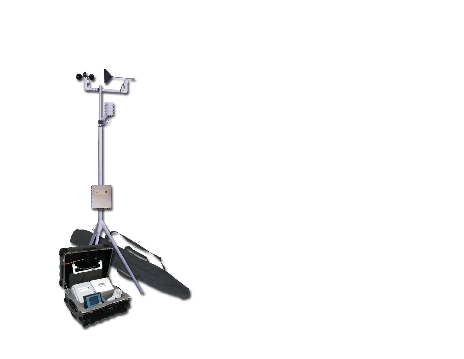
The Pegasus FlyAway Kit portable weather station combines digital
quality and professional-grade equipment with the need for a highly
mobile weather station to create a state-of-the-art, rapid deployment
weather monitoring system for Emergency Operations.
Pegasus is specifically designed for firefighters, HazMat,
Emergency Management, and Disaster Preparedness personnel
when weather monitoring is crucial to the public’s safety.
Pegasus allows Accident and Incident Commanders to create a fully
functional weather operation within minutes, automatically collecting
weather data and providing a cost-effective force-multiplier not
available in any other portable weather station.
Specifications
Temperature
Type: digital semiconductor
Range: -67° to 257°F
Accuracy: ±0.9°F
Resolution: 0.01°F
Barometric Pressure
The barometric pressure sensor is located inside the Control
Module and is part of the weather station circuit board.
Type: silicon shear stress strain gauge; temperature compensated
and calibrated
Range: 27 to 33.96 in. Hg
Accuracy: ±0.03 in. Hg over range (at sea level, with temperature
between 32° and 182°F)
Resolution: 0.01 in. Hg
Wind Speed
Type: chopping disc anemometer, three cups
Range: 0 to 125 mph
Columbia Weather Systems, Inc.
Page 9

Pegasus FlyAway Kit 9
___________________________________________________________________
Accuracy: ±1 mph from 5 to 20 mph, ±5% from 20 to 125 mph
Mechanical Threshold: 0.5 mph
Resolution: 1 mph
Wind Direction
Type: wind vane using digital gray code
Range: 360 degrees.
Relative Humidity
Type: Capacitance
Range: 0 to 100%
Accuracy: ±3% (or better) from 10 to 90% RH at 68° F
Temperature Effect: <±1.5% RH from 14° F to 140° F
Stability: ±2% RH over 2 years
Resolution: 1% RH
Wireless Transceiver
Frequency: 2.402 - 2.478 GHz, FHSS (license-free)
Range: Up to 500 feet (152 m) indoors; Up to 10,000 feet (3050 m)
line-of-sight
Output Power: 200 mW
Battery Power
Output: 12 VDC, 12 AH, 32-hour operation
SLA (Sealed Lead Acid) Gel Batteries
Control Module
Dimensions: 14 x 11 x 6.5 inches
Weight: 6.7 lbs/3 kg.
System Weight
Weather station and caring case: 38 lbs
Tripod and canvas bag: 17 lbs
Battery system and case: 23 lbs
Columbia Weather Systems, Inc.
Page 10
Pegasus FlyAway Kit 10
___________________________________________________________________
SECTION 2: PHYSICAL
DESCRIPTION
Columbia Weather Systems, Inc.
Page 11
Pegasus FlyAway Kit 11
___________________________________________________________________
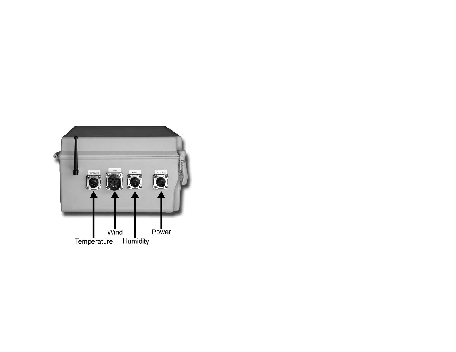
Control Module
The Control Module consists of the System board and a 2.4 GHz
transceiver housed in a weatherproof fiber glass enclosure with
external sensor and power connectors.
The System board has an on-board barometric pressure sensor and
a system fuse (including a spare fuse). The System board also has
in-line rechargeable batteries to preserve the datalog and system
configuration when power is absent.
The Control Module dimensions are: 14 x 11 x 6.5 inches and
weighs: 6.7 lbs/3 kg.
Control Module Connections
Columbia Weather Systems, Inc.
Page 12
Pegasus FlyAway Kit 12
___________________________________________________________________
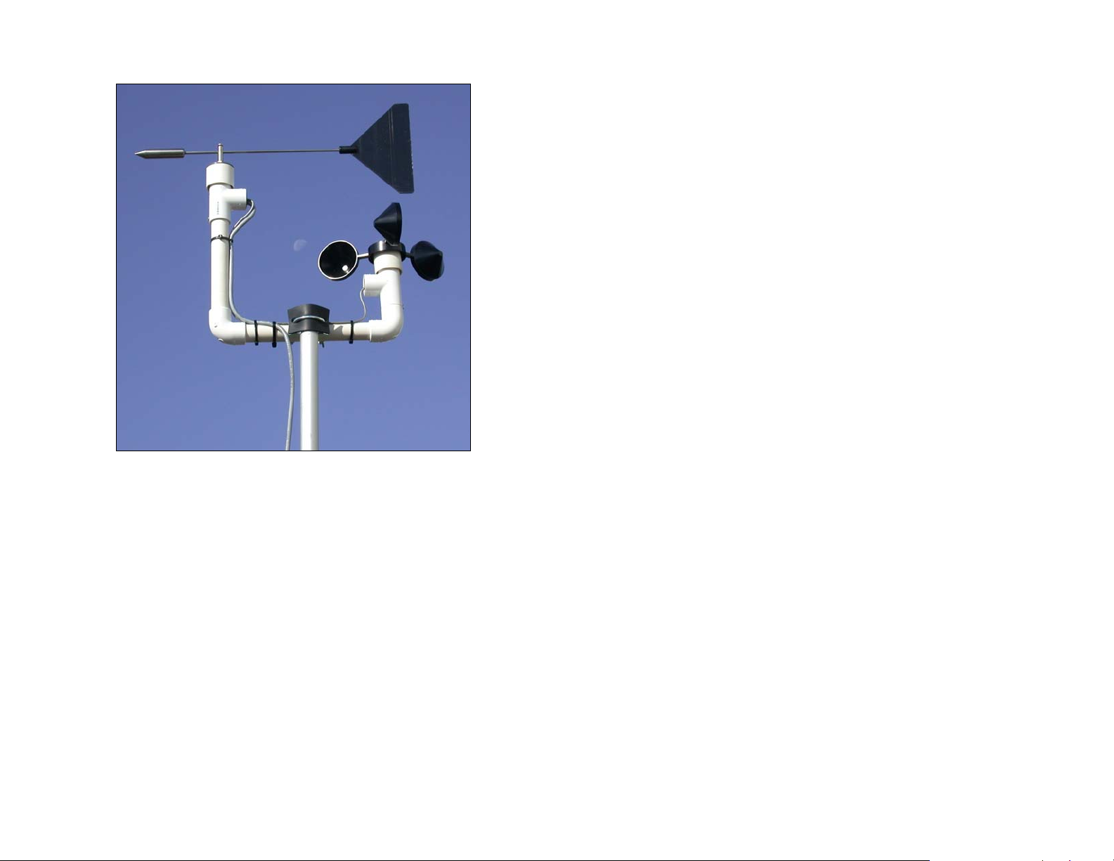
Wind sensor
The wind speed and direction sensors use a solid state, infrared
optical design to decrease wear and improve reliability. These
rugged sensors, with a design incorporating years of experience
and testing, are enclosed in a rugged PVC housing surrounding
stainless steel parts. These sensors operate in extreme temperature
and wind conditions for years.
Columbia Weather Systems, Inc.
Page 13
Pegasus FlyAway Kit 13
___________________________________________________________________
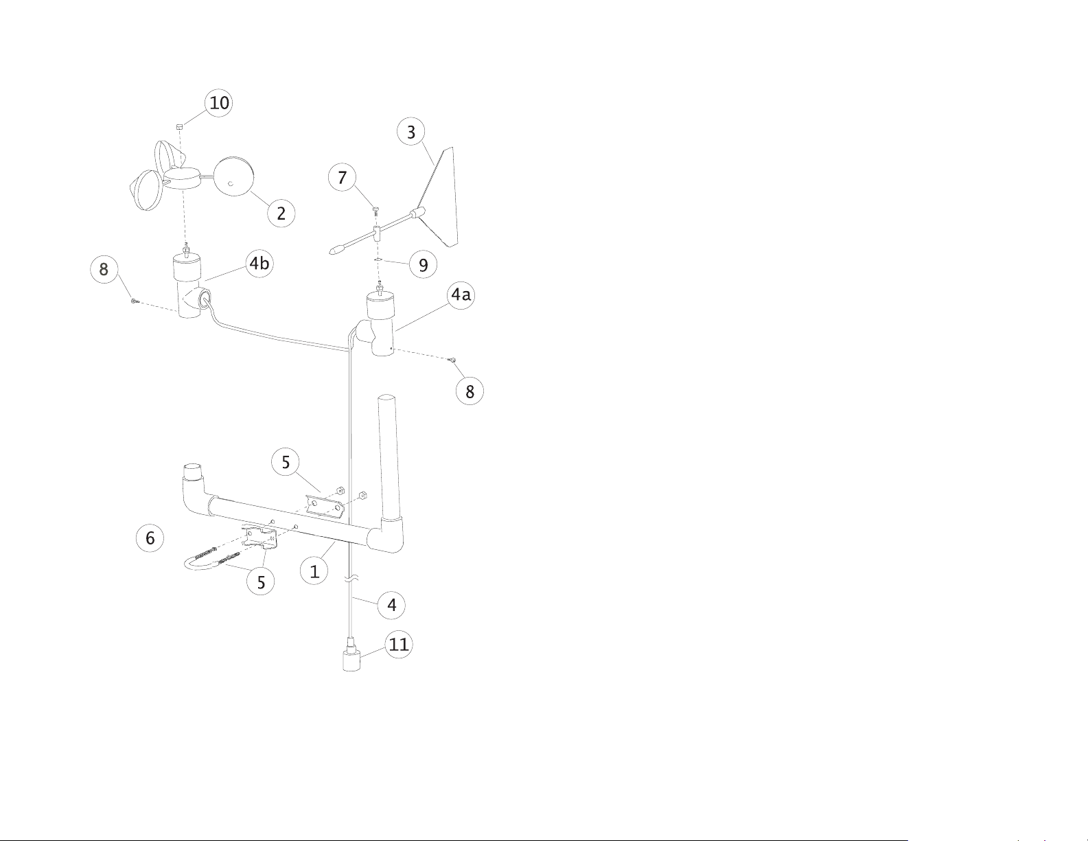
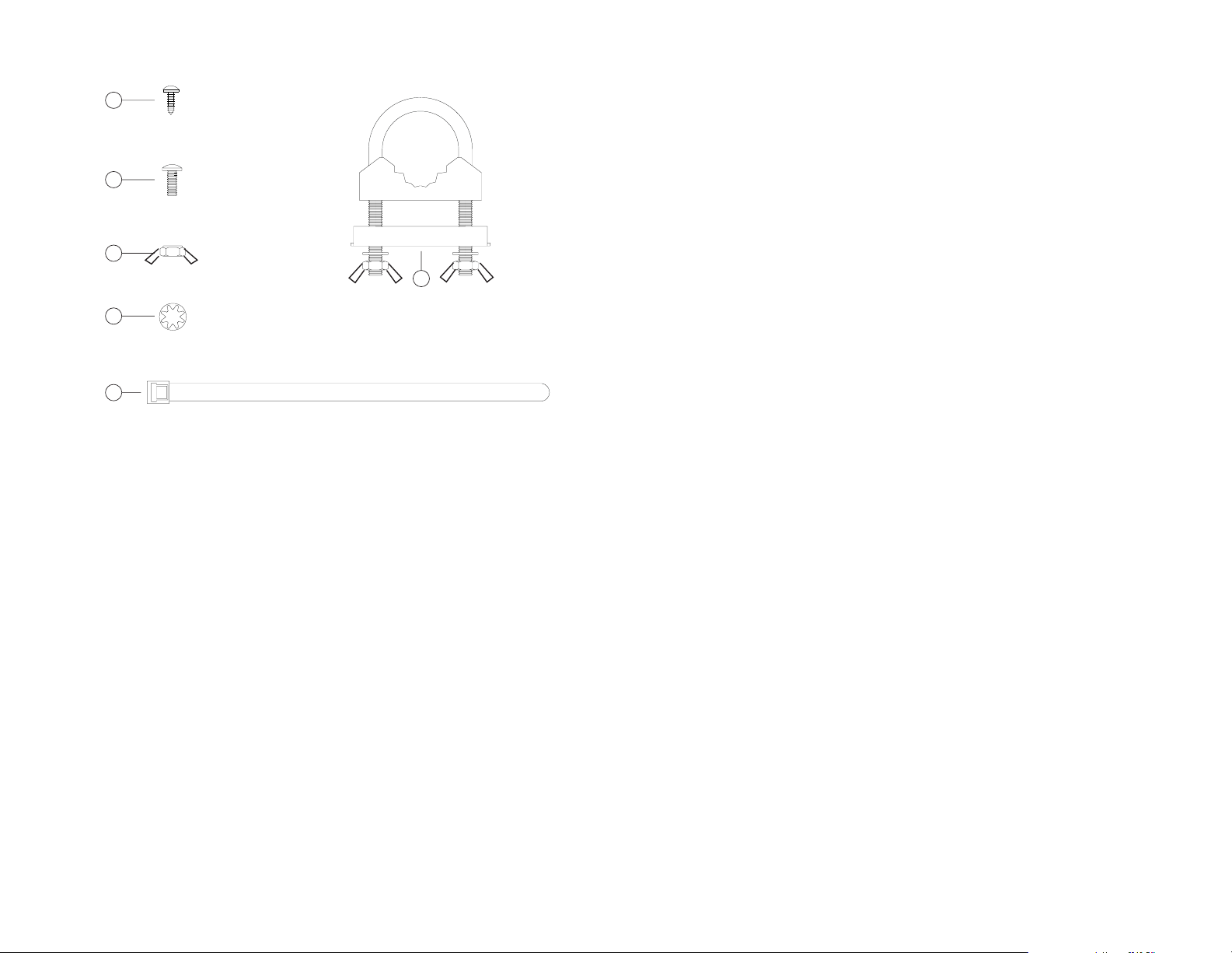
Wind sensor components
Columbia Weather Systems, Inc.
Page 14
Pegasus FlyAway Kit 14
___________________________________________________________________
Hardware Kit Assembly Kit
8
SHEET METAL SCREW
FOR CROSS-ARM SUPPORT,
STAINLESS STEEL (QTY 2)
7
TOP SCREW
FOR DIRECTION VANE,
STAINLESS STEEL
10
TOP LOCK NUT
FOR WIND SPEED SENSOR,
STAINLESS STEEL
9
INTERNAL STAR WASHER
FOR WIND DIRECTION SENSOR,
STAINLESS STEEL
6
BLACK PLASTIC TIE-WRAPS (QTY 6)
1. Cross Arm Support
2. Wind Cup Hub Assembly (with spare top lock nut)
5
U-BOLT
ASSEMBLY
PLATED STEEL
3. Wind Direction Vane (with spare top screw)
4. 10-foot wind sensor cable with connector assembly
4a. Wind Direction sensor body (white, T-shaped, heavy duty PVC
fitting with two cables protruding)
4b. Wind Speed sensor body (white, T-shaped, heavy duty PVC
fitting with one cable protruding)
5. Hardware Assembly Kit
6. Black plastic tie wraps (UV-resistant)
7. Top screw (for clamping the direction vane shaft to the vane
holder), stainless steel
8. Stainless steel sheet metal screws (for mounting wind sensors
to Cross Arm Support)
9. Top lock nut (to be placed on threaded shaft of wind speed
sensor, above wind cup assembly
10. Top lock nut (to be placed on threaded shaft of wind speed
sensor, above wind cup assembly), stainless steel
11. Wind Sensor Cable Connector
Columbia Weather Systems, Inc.
Page 15
Pegasus FlyAway Kit 15
___________________________________________________________________
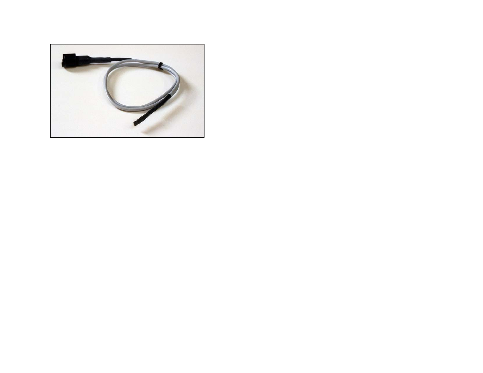
Temperature sensor
The Pegasus comes standard with one temperature sensor with 10
feet of cable. This digital, semiconductor-type probe reduces
susceptibility to noise interference, and increases accuracy. The
sensor is calibrated at the factory traceable to NIST standards.
Columbia Weather Systems, Inc.
Page 16
Pegasus FlyAway Kit 16
___________________________________________________________________
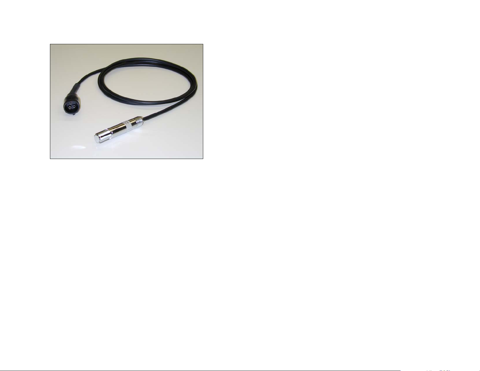
Relative Humidity sensor
This optional capacitive relative humidity sensor is compact and
easy to use. It is easily installed in the self-aspirating radiation shield
for protection from the sun and rain. This sensor offers long-term
stability with minimal drift. Because the sensor is a capacitive
device, it will not be affected by surface contamination in unclean
environments. Since the sensor element is socketed and laser
trimmed it can be easily replaced in the field without any additional
calibration. The relative humidity sensor comes with a standard 10foot cable and a quick disconnect connector.
Columbia Weather Systems, Inc.
Page 17

Pegasus FlyAway Kit 17
___________________________________________________________________
Tripod
Tripod Model T-1000 is designed to provide up to 10 feet of stable,
secure support for your meteorological sensors.
The T-1000 is constructed from welded aluminum and is powder
coated for appearance and longevity. The 15-pound tripod can
Columbia Weather Systems, Inc.
Page 18

Pegasus FlyAway Kit 18
___________________________________________________________________
easily support up to 60 pounds of equipment. The tie-down kit
allows for additional security in high-wind areas.
Set up takes less than five minutes. Simply insert the legs into the
main body and install the stainless steel retainer pins. Extend the
mast to the desired height and insert another retainer pin. Install
the guy wires and you’re ready to go!
Specifications
Capacity: Supports up to 60 lbs.
Shipping Weight: 17lbs
Shipping Box Dimensions: 63" x 8" x 8"
Item # Description Qty
1. Body/Mast Assembly 1
2. Legs 3
3. Legs retainer Pins 4
4. Guy Wire Ring with 1
3 Wires and Turnbuckles
5. Anchor Screw with Chain 1
6. Spring Clamp 1
7. Mast retainer Pin 1
Columbia Weather Systems, Inc.
Page 19

Pegasus FlyAway Kit 19
___________________________________________________________________
WeatherMaster 2000 Software
(optional)
WeatherMaster 2000 is a professional grade weather monitoring
software. This software package is designed for specialized markets
that require robust weather calculations, interoperability with
computer models, and data interfaces to other industrial systems.
WeatherMaster 2000 utilizes Microsoft Access database for easy
data access and manipulation.
WeatherMaster 2000 is also capable of monitoring multiple stations
via a wireless link.
Columbia Weather Systems, Inc.
Page 20

Pegasus FlyAway Kit 20
___________________________________________________________________
Weather View 32 Software (optional)
Operating in Windows graphic environment, Weather View 32 helps
you monitor, record, and store local weather data for current or
future analysis.
Weather View 32 offers:
• User-defined real time monitoring display
• Internet and email interface
• Calculated parameters including wind chill, dew point, heat
index and degree days
• Monthly calculations for degree days heating and cooling
• Full-featured graphing and printing capabilities
• Six separate alarms functions
• A Climatological database that covers the U.S. and Canada
• Modem access for remote weather stations
Columbia Weather Systems, Inc.
Page 21

Pegasus FlyAway Kit 21
___________________________________________________________________
RetrieverCC Palm OS Software
(optional)
TM
RetrieverCC
communication with the Capricorn 2000
TM
Kit
weather stations. The RetrieverCC, running on a Palm
provides a user-friendly PalmTM program for
TM
and Pegasus FlyAway
handheld, communicates with the weather station via an RS-232
port to view current weather data, extract logged data and perform
other configuration functions.
RetrieverCC can download the datalog from multiple weather
stations for export to a PC for additional data analysis and storage.
Columbia Weather Systems, Inc.
Page 22

Pegasus FlyAway Kit 22
___________________________________________________________________
Features
• Operates on most Palm Handhelds (see Requirements).
• Easy list-based selection of the weather station functions.
• Parses data output into easily readable fields.
• Data capture capability.
• Retains multiple data-capture sessions (capacity subject only to
available memory).
• User-named data-capture sessions.
• Review of existing data capture sessions on the handheld.
Requirements
• A Palm device running Palm OS® version 3.1.1 or later (Palm V-
series, IIIx, IIIe, IIIxe, IIIc, all m-series, i-series, and also an OS
upgraded Palm III).
• Palm Desktop Software installed on the PC.
• An RS-232 serial cable for the handheld.
• A Capricorn 2000 serial cable (included with software).
Retriever CC is a trademark of Chesapeake Technology
International
Palm is a trademark of Palm, Inc.
Columbia Weather Systems, Inc.
Page 23

Pegasus FlyAway Kit 23
___________________________________________________________________
Weather Display Console (Optional)
The Capricorn 2000 Weather Display uses “intelligent” touch-screen
technology. With its programmable microprocessor and abundant
memory, the Capricorn 2000 Weather Display can display weather
information, perform complex computations, and store relatively
large amounts of weather data.
The Capricorn 2000 Weather Display is also available in Aviation
and Agricultural Editions:
Aviation Edition: Density Altitude with additional wind speed and
direction calculations and charts.
Agricultural Edition: Evapotranspiration and degree day
calculations.
The Weather Display is also available in a 19” rack-mount chassis.
Columbia Weather Systems, Inc.
Page 24

Pegasus FlyAway Kit 24
___________________________________________________________________
SECTION 3: INSTALLATION
1. Install the radiation shield by slipping it over the sensor
mast extension. Do not tighten wing nuts at this time.
2. Slip the guy wire collar over the sensor mast
3. Install the wind sensor assembly on the top of the mast.
Align the North mark on the wind sensor clamp to the North
mark on the mast and tighten the assembly using the two
wing nuts.
4. Connect the three legs using the pins as shown below.
Columbia Weather Systems, Inc.
Page 25

Pegasus FlyAway Kit 25
___________________________________________________________________
5. Extend the mast to full length and secure with the attached
pin. Be sure that the North marks on the sensor mast and
the tripod body are aligned.
6. Tighten the guy wire turnbuckles so that the sensor mast is
aligned up right.
7. Position the radiation shield toward the lower part of the
sensor mast extension and tighten using the two wing nuts.
Columbia Weather Systems, Inc.
Page 26
Pegasus FlyAway Kit 26
___________________________________________________________________
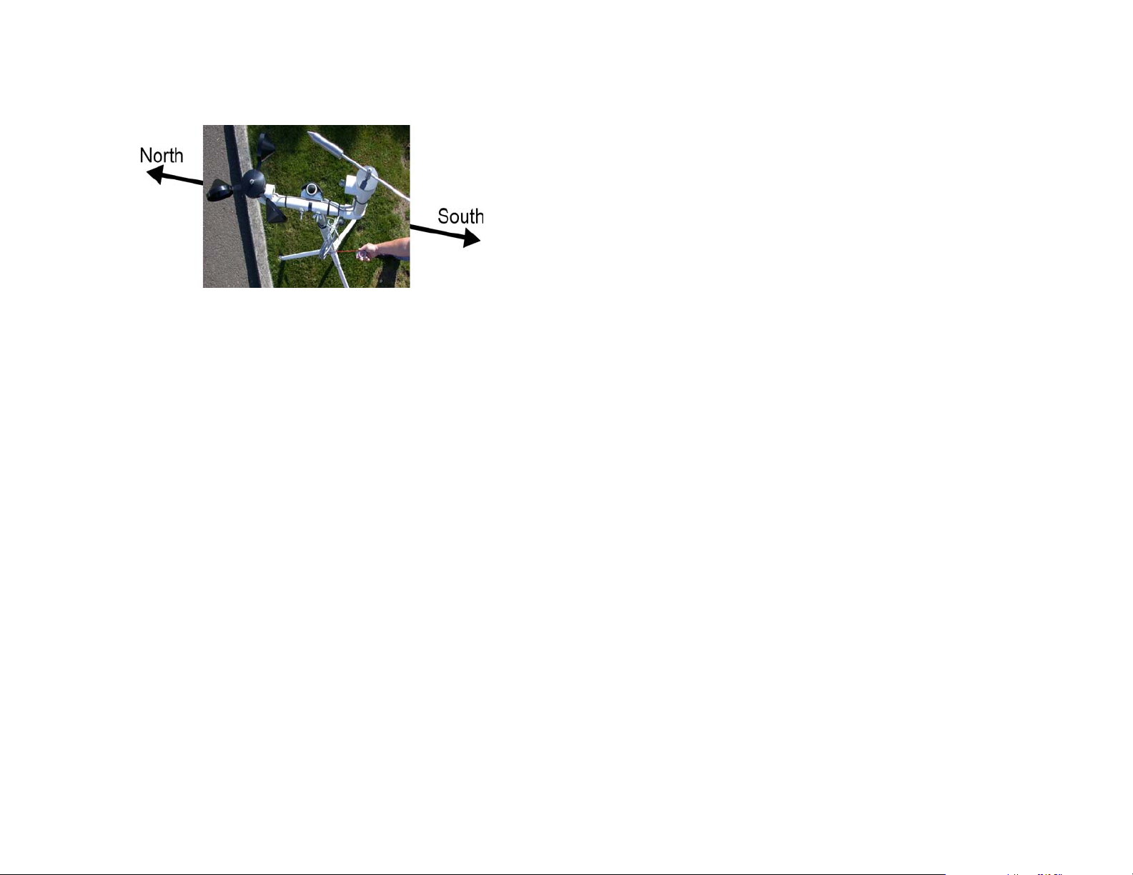
8. Using the attached compass, orient the entire tripod system
to magnetic North. The wind sensor cross arm assembly
should be aligned with the North/South direction and the
wind cups are pointing to North as shown below.
9. Secure the tripod using the spring-loaded chain attached to
the corkscrew drilling stake (for soil) or the pavement spike
(for hard surfaces). Pavement spikes can be purchased
from local hardware stores.
10. Attach the Control Module to the tripod using the buckle
strap.
11. Connect the sensor cables to the Control Module.
12. Place the battery in its case at the base of the tripod.
Connect the power cable to the battery terminals first and
then to the Control Module external connector.
The system is now operational and is ready to transmit weather
data.
Columbia Weather Systems, Inc.
Page 27

Pegasus FlyAway Kit 27
___________________________________________________________________
Section 4: Display Console
and Software Installation
The Pegasus FlyAway Kit offers several options to view and collect
the weather data. All of these options (with the exception of the
RetrieverCC) use a wireless link to communicate with the control
module.
Weather Display Console
Please refer to the Weather Display user manual for installation and
operation instructions.
WeatherMaster 2000 Software
Please refer to the WeatherMaster 2000 user manual for installation
and operation instructions.
Weather View 32 Software
Please refer to the Weather View 32 user manual for installation and
operation instructions.
RetrieverCC Palm Software
Please refer to the RetrieverCC user manual for installation and
operation instructions.
Columbia Weather Systems, Inc.
Page 28

Pegasus FlyAway Kit 28
___________________________________________________________________
Section 5: Operation
The Pegasus communicates with a computer or Weather Display
console via wireless interface. The Control Module has two ports
available on the back panel (RJ-11 jacks).
RS-232 Modem serial port
This is the main serial port in the system. It is usually connected to
the radio transceiver for communication with a computer or a
Weather Display.
RS-232 Aux serial port
This is a secondary serial port. It is usually used for direct
communication with a computer or a Palm device.
Communication
Normally the weather software or the Weather Display is used for
monitoring. Configuration is done through the menu selection of the
software or the display console.
The commands described in this section are used when the user
wishes to communicate directly with the system using a “terminal”
software program such as Hyper Terminal (available with Windows
operating systems).
The protocol for both serial ports is the following:
Bits per Second (baud rate): 9600
Data bits: 8
Parity: None
Stop bits: 1
Flow control: None
All commands must be entered using upper case letters and
followed by a carriage return.
The weather station will return "ok" after the results of each
command. If the command is incorrect, the weather station will
return "?".
Columbia Weather Systems, Inc.
Page 29

Pegasus FlyAway Kit 29
___________________________________________________________________
Setting date and time
SET-DATE: This command is used to set the internal calendar to
the appropriate date. It uses space delimiters between the month
field, the day field, the year field, and the command field.
Example: 12 25 96 SET-DATE sets the date to 12/25/1996 and 1 5
01 SET-DATE sets the date to 1/5/2001
SET-TIME: This command is used to set the internal clock to the
appropriate military time (24 hours clock). It uses space delimiters
between the hours field, minutes fields and the command field.
Example: 13 46 SET-TIME sets the time to 1:46 PM
Displaying date and time
DATE-TIME: This command is used to display the system date and
time. When used the weather station will return the date followed by
the time, comma delimited.
Example: 02/11/1998,13:20ok
Displaying current sensor readings
There are three ways to display current sensor readings:
The POLL command
POLL: This command is used to display the current sensor readings
in a report format. When a POLL command is issued, the weather
station will interrogate all the sensors and will display the
information
Example:
11:00 Time
02/11/1998 Date
50.14 Degrees F Temperature 1
70.89 Degrees F Temperature 2
68.33 Degrees F Temperature 3
64.46 Degrees F Temperature 4
29.88 Inches Hg Barometric Pressure
006 MPH Wind Speed
SE Wind Direction
073 Percent Relative Humidity
00.06 Inches Rain (Today)
04.43 Volts Leaf Wetness
01.30 Volt X1
04.58 Volts X2
ok
Columbia Weather Systems, Inc.
Page 30

Pegasus FlyAway Kit 30
___________________________________________________________________
The SAMPLE command
SAMPLE: This command is used to display the current sensor
readings in a one line record format (the same format as the
datalog). The record starts with the letter S followed by the date and
time of the sample, followed by the sensor values and ends with a
check sum value. All of these fields are comma delimited.
Example:
S,02/11/98,11:09,36WD,003WS,00.06R,072RH,29.88P1,+050.59T1,+070.77T2,+068.23T3,
+064.60T4,04.43LW,0.00X1,0.00X2,6007ok
Where, WD is wind direction, WS is wind speed in MPH, R is rain
fall in inches, RH is relative humidity percentage, P1 is barometric
pressure in Inches-Hg, T1 through T4 are the four temperature
sensors in degrees F, LW is leaf wetness in volts, X1 is typically
solar radiation (5.00 volts equals 2000 Weather Master 2000-2) and
X2 is used for additional sensors (X1 and X2 channels are not
available with the Pegasus FlyAway Kit).
Temperature channels that are not defined or connected will have a
+255.00 reading.
Wind direction is displayed in a 64 degree compass as follows:
0 N
4 NNE
8 NE
12 ENE
16 E
20 ESE
24 SE
28 SSE
32 S
36 SSW
40 SW
44 WSW
48 W
52 WNW
56 NW
60 NNW
The Short commands
WD: will display wind direction in a 64 compass points
WS: will display wind speed in MPH
R1: will display the rain fall for the day in inches
RH: will display relative humidity percentage
P1: will display the barometric pressure in inches-Hg
Columbia Weather Systems, Inc.
Page 31

Pegasus FlyAway Kit 31
___________________________________________________________________
T1: will display the temperature for the first temperature probe in
degrees F
T2: will display the temperature for the second temperature probe in
degrees F
T3: will display the temperature for the third temperature probe in
degrees F
T4: will display the temperature for the fourth temperature probe in
degrees F
LW: will display leaf wetness in volts. The range may vary per
sensor. Typically, 0.5 volts indicates saturated condition and 4.5
volts indicates dry conditions.
X1 and X2 channels are not used with the Pegasus FlyAway Kit
Datalog
The Pegasus weather station has a built in circular datalogger. The
datalog holds records of sensor readings (Samples) and High/Low
information. Both types of records (Samples and High/Low) are
recorded at user defined intervals.
The datalog can hold up to 511 records. A Sample occupies on
record and High/Low information occupies four records.
Setting datalog intervals
The interval for the Sample records in the datalog is user selectable.
The interval duration is restricted to the following: 1, 2, 3, 4, 5, 6, 10,
15, 20, 30, and 60 minutes.
n MEAS-INT: This command sets the Sample interval in the datalog.
n is the interval duration in minutes.
Example: 15 MEAS-INT will cause the weather station to save a
Sample record every 15 minutes.
Setting Hi/Lo intervals
The interval for the High/Low records in the datalog is user
selectable. The interval duration is restricted to the following: 1, 2, 3,
4, 6, 8, 12 and 24 hours.
n HI/LO-INT: This command sets the High/Low interval in the
datalog. n is the interval duration in hours.
Example: 12 HI/LO-INT will cause the weather station to save
High/Low records (total of four records) every 12 hours.
Columbia Weather Systems, Inc.
Page 32

Pegasus FlyAway Kit 32
___________________________________________________________________
Displaying the datalog
ALL: This command will display the complete datalog (511
maximum records)
Example: In this example the Sample interval is set at one minute
and the High/Low interval is set at one hour and the datalog has 13
record (9 Sample records and 4 High/Low records).
13 records
S,02/11/98,13:56,32WD,007WS,00.07R,074RH,29.85P1,+052.31T1,+071.62T2,+069.17T3,
+065.57T4,01.88LW,0.00X1,0.00X2,6015
S,02/11/98,13:57,32WD,005WS,00.07R,074RH,29.86P1,+052.74T1,+071.83T2,+069.26T3,
+065.69T4,01.70LW,0.00X1,0.00X2,6019
S,02/11/98,13:58,32WD,006WS,00.07R,072RH,29.85P1,+052.76T1,+071.64T2,+069.35T3,
+065.75T4,01.74LW,0.00X1,0.00X2,6020
S,02/11/98,13:59,32WD,006WS,00.07R,071RH,29.85P1,+052.94T1,+071.86T2,+069.36T3,
+065.81T4,01.74LW,0.00X1,0.00X2,6022
H,02/11/98,14:00,013,13:25WS,081,13:40RH,29.86,13:27P1,+053.23,14:00T1,+072.27,13:
52T2,+069.59,13:31T3,+065.88, 14:00T4,01.70,13:57LW,0.00,14:00X1,0.00,14:00X2,8351
L,02/11/98,14:00,013,13:25WS,067,13:25RH,29.84,13:25P1,+050.17,13:39T1,+071.29,13:2
6T2,+068.33,13:42T3,+065.34, 13:25T4,04.41,13:27LW,0.00,00:00X1,0.00,00:00X2,8349
S,02/11/98,14:00,28WD,000WS,00.07R,071RH,29.85P1,+053.23T1,+072.02T2,+069.26T3,
+065.88T4,01.76LW,0.00X1,0.00X2,5998
S,02/11/98,14:01,28WD,003WS,00.07R,071RH,29.85P1,+053.67T1,+072.52T2,+068.91T3,
+065.88T4,01.78LW,0.00X1,0.00X2,6018
S,02/11/98,14:02,32WD,006WS,00.07R,069RH,29.85P1,+053.70T1,+072.86T2,+068.89T3,
+065.86T4,01.84LW,0.00X1,0.00X2,6027
S,02/11/98,14:03,32WD,003WS,00.07R,068RH,29.85P1,+053.73T1,+073.13T2,+069.21T3,
+065.86T4,01.88LW,0.00X1,0.00X2,6009
S,02/11/98,14:04,28WD,005WS,00.07R,067RH,29.85P1,+053.41T1,+072.48T2,+069.36T3,
+065.86T4,01.94LW,0.00X1,0.00X2,6021ok
Note that the Sample records start with the letter S and the
High/Low records start with the letter H and L respectively.
NOW: This command will display the last record in the datalog
n GET: This command will display a user defined number of records
in the datalog, where n is the number of records.
Example: 10 GET will display the last ten records in the datalog.
Resetting Hi/Lo
RESET-HI/LO: This command will erase the high/low values from
memory for the current high/low interval.
Columbia Weather Systems, Inc.
Page 33

Pegasus FlyAway Kit 33
___________________________________________________________________
Resetting the datalog
RESET-DATA: This command will erase the datalog and will insert
one current Sample record.
Displaying current Hi/Lo
HIGH: This command will display the current high record. The High
record starts with the letter H followed by the date and time the
record was requested followed by the high values and the time for
wind speed, relative humidity, pressure, temperatures, leaf wetness
and two undefined sensors (X1 and X2). The high value of wind
speed is the wind gust.
Example:
H,02/11/98,14:00,013,13:25WS,081,13:40RH,29.86,13:27P1,+053.23,14:00T1,+072.27,13:
52T2,+069.59,13:31T3,+065.88, 14:00T4,01.70,13:57LW,0.00,14:00X1,0.00,14:00X2,8351
LOW: This command will display the current low record. The Low
record starts with the letter L followed by the date and time the
record was requested followed by the low values and the time for
wind speed, relative humidity, pressure, temperatures, leaf wetness
and two undefined sensors (X1 and X2). The low value of wind
speed is the high 4 second sustained wind average.
Setting temperature offsets
Temperature offsets are used to calibrate the temperature probes.
n TCAL#: This command is used to enter an offset for a temperature
probe. Where n is the offset in 1/100 of a degree F and # is the
temperature probe number.
Example: 231 TCAL2 adds 2.31 degree F to the temperature
reading from temperature probe two and -231 TCAL2 subtracts 2.31
degrees F from the reading.
Please refer to the Temperature Calibration section for more
information.
Setting barometric pressure altitude
and offset
n ALT: This command sets the altitude of the weather station, where
n is the altitude in feet.
Example: 225 ALT sets the altitude to 225 feet above see level.
n BAR-OFFSET: This command is used to enter an offset to the
barometric pressure reading, where n is the offset in 1/100 of In.Hg.
Columbia Weather Systems, Inc.
Page 34

Pegasus FlyAway Kit 34
___________________________________________________________________
Example: 34 BAR-OFFSET adds 0.34 in.Hg to the barometric
pressure reading and -34 BAR-OFFSET subtract 0.34 in.Hg from
the reading.
Please refer to Barometric Pressure Calibration for more
information.
Display current settings
PARAMETERS: This command displays the current weather station
settings and the number of records in the datalog.
Example:
Date & Time 02/11/1998,17:31
Measurement interval 1 minutes
Hi/Lo interval 1 hours
Records in memory 262
Pressure offset 38
Altitude 225
Temperature 1 offset 255
Temperature 2 offset -25
Temperature 3 offset 55
Temperature 4 offset 155 ok
Continuous display of direction
NORTH: This command continuously displays the wind direction.
This command is used for locating the north direction on the wind
sensor. An <Esc> followed by a carriage return terminates this
command.
Continuous display of wind information
1 XFER: This command continuously displays a Sample record
every one minute and wind speed and direction every one second.
The wind speed and direction record starts with the letter W
followed by three digits for wind speed in MPH followed by two digits
for wind direction.
Example:
W00124
S,02/11/98,17:44,24WD,001WS,00.08R,085RH,29.82P1,+048.56T1,+070.85T2,+067.24T3,
+065.08T4,01.74LW,0.00X1,0.00X2,6014
W00224
W00224
W00124
Columbia Weather Systems, Inc.
Page 35

Pegasus FlyAway Kit 35
___________________________________________________________________
W00124
W00124
W00120okok
An <Esc> followed by a carriage return terminates this command.
XSET: This command defines the frequency the Sample record is
displayed in the XFER output. The default frequency of the Sample
record in the XFER output is 60 seconds. This frequency can be
changed using the XSET command. For example, 15 XSET will
cause the Sample record to be issued every 15 seconds. XSET will
change the frequency of the XFER output on both serial ports.
CONT: This command will continuously output the Sample record at
a specified interval. For example, 5 CONT will output a Sample
record every 5 seconds. The time interval is limited to a range of 1
to 16 seconds.
S,05/01/99,09:44,40WD,000WS,00.00R,022RH,29.10P1,+070.70T1,+255.00T2,04.80LW,5.
00X1,0.10X2,4923
S,05/01/99,09:44,40WD,000WS,00.00R,023RH,29.09P1,+070.70T1,+255.00T2,04.80LW,5.
00X1,0.10X2,4932
S,05/01/99,09:44,40WD,000WS,00.00R,023RH,29.09P1,+070.70T1,+255.00T2,04.80LW,5.
00X1,0.10X2,4932
S,05/01/99,09:44,40WD,000WS,00.00R,023RH,29.10P1,+070.70T1,+255.00T2,04.80LW,5.
00X1,0.10X2,4924
S,05/01/99,09:45,40WD,000WS,00.00R,023RH,29.10P1,+070.70T1,+255.00T2,04.80LW,5.
00X1,0.10X2,4925
S,05/01/99,09:45,40WD,000WS,00.00R,023RH,29.10P1,+070.70T1,+255.00T2,04.80LW,5.
00X1,0.10X2,4925
S,05/01/99,09:45,40WD,000WS,00.00R,023RH,29.10P1,+070.70T1,+255.00T2,04.80LW,5.
00X1,0.10X2,4925
S,05/01/99,09:45,40WD,000WS,00.00R,023RH,29.10P1,+070.70T1,+255.00T2,04.80LW,5.
00X1,0.10X2,4925
S,05/01/99,09:46,40WD,000WS,00.00R,023RH,29.10P1,+070.72T1,+255.00T2,04.80LW,5.
00X1,0.10X2,4928
S,05/01/99,09:46,40WD,000WS,00.00R,023RH,29.10P1,+070.72T1,+255.00T2,04.80LW,5.
00X1,0.10X2,4928okok
An <Esc> followed by a carriage return terminates this command.
The output will stop after one more Sample record is issued. For
example, if CONT is set to repeat the Sample record every 15
Columbia Weather Systems, Inc.
Page 36

Pegasus FlyAway Kit 36
___________________________________________________________________
seconds (15 CONT) and an <ESC><RETURN> was entered, one
more Sample record will be issued before the double ok is displayed
indicating that the command is terminated.
Columbia Weather Systems, Inc.
Page 37

Pegasus FlyAway Kit 37
___________________________________________________________________
SECTION 6: CALIBRATION
Calibrating the Barometric Pressure
Sensor
The barometric pressure sensor is calibrated at the factory to a
highly accurate digital pressure gauge (±0.02% of full range) and
traceable to NIST and, therefore, it requires no further calibration.
The barometric pressure sensor in the Pegasus is temperature
compensated from 32° to 185° F and has an accuracy of ±0.03
in.Hg.
Altitude Setting
After calibration at the factory, the altitude is set to zero. To get an
accurate barometric pressure reading, the local altitude needs to be
set in the weather station.
To set the altitude, use the ALT command and enter the altitude in
feet. Please refer to Section 4: Operation for more information. The
altitude can also be set using weather software or display console.
Please refer to the software or display console user manual.
Note: The electronic transducer used to measure air pressure is
sensitive to changes in elevation of as little as 10 ft. (3 m).
Optional Calibration Procedure
Even though the barometric pressure sensor is calibrated at the
factory, the sensor can be re-calibrated on-site. This might be
required if the original barometric pressure offset has been erased
from memory, or if weather station needs to match a local source.
To re-calibrate the barometric pressure on-site:
Using a terminal program, set the barometric pressure offset to zero
by entering: 0 BAR-OFFSET
Wait approximately 5 seconds, then take a pressure reading using
SAMPLE, POLL or P1
Record the barometric pressure from a local reliable source at the
same elevation as the Pegasus.
Calculate the barometric pressure offset as follows:
Barometric Pressure Offset = Source Reading - Pegasus Reading.
Columbia Weather Systems, Inc.
Page 38

Pegasus FlyAway Kit 38
___________________________________________________________________
Enter the barometric pressure offset in 1/100 of in.Hg using the
BAR-OFFSET command.
Calibrating the Wind Sensors
The wind speed sensor contains no components that can be
calibrated by the user. Refer to the Installation Section for sensor
North orientation.
Calibrating the Temperature Sensors
All Temperature sensors are calibrated at the factory to a superior
grade ASTM mercury thermometer traceable to NIST. The
calibration offset is recorded on the temperature sensor and on the
end of the cable.
After initializing all the temperature sensors, enter the temperature
offsets using the TCAL command. Please refer to Section 4:
Operation for more information. TCal offsets are labeled on the
sensor cable.
To calibrate the temperature sensors on-site, perform the following
steps:
Prepare an ice bath by mixing two cups of crushed ice in two cups
of water. Use an insulated container for best results. Allow the
temperature throughout the ice bath to stabilize by waiting for about
twenty minutes.
Stir the ice bath to mix the ice and water, wait for the ice to separate
from the water, place the temperature sensor in the ice bath. Make
sure that the sensor is not in direct contact with ice.
Take a temperature reading from the Pegasus using SAMPLE or
POLL.
Calculate the temperature offset as follows:
Temperature offset = (32 - Pegasus reading) * 100
Enter the temperature offset using the TCAL command. Please refer
to Section 4: Operation for more information.
Record the temperature offset on a label attached to the sensor.
Repeat the process for any other temperature sensor.
Columbia Weather Systems, Inc.
Page 39

Pegasus FlyAway Kit 39
___________________________________________________________________
Calibrating the Humidity Sensor
The humidity sensor is calibrated at the factory and is traceable to
NIST. No field calibration is required.
Columbia Weather Systems, Inc.
Page 40

Pegasus FlyAway Kit 40
___________________________________________________________________
SECTION 7: MAINTENANCE
In normal use, the Pegasus should require very little maintenance.
In the event of any problems, follow the procedures contained in
Section 8: Troubleshooting, to determine whether the components
are defective. If defective and needs to be returned to the factory for
repair, refer to the Return For Repair Procedure in Section 9: User
Support Information.
Control Module
The Control Module contains sensitive electronic components and
should not be serviced by the user. If the LED on the inside circuit
board is not on, check for proper installation of the battery supply
system. Check to see if the fuse on the Control Module board needs
to be replaced. If necessary, replace it with a 1.0 amp 250V fast
acting fuse.
Barometric Pressure Sensor Maintenance
The barometric pressure sensor is located inside the weatherproof
enclosure and should not be serviced by the user.
Temperature Sensor Maintenance
Check the temperature sensor cables during installation and
periodically thereafter to make sure they contain no cuts, kinks or
other abnormalities.
Wind Sensor Maintenance
Do not attempt to oil, grease or otherwise lubricate the wind
sensors. The wind speed and direction bearings are permanently
sealed and should not be tampered with. If it appears that the
displayed wind speed values are substantially less than existing
conditions, or that the wind direction display is sluggish in
responding to changes in wind direction, it may be that the bearings
need service. This can be tested by spinning the sensors. They
should spin freely. If they do not, call the factory for service. All or
part of the wind sensors may need to be replaced. Since the circuit
is molded into the wind sensor housing, an electronic defect
requires replacement of the sensor. The wind sensors are not
designed for field repair.
Columbia Weather Systems, Inc.
Page 41

Pegasus FlyAway Kit 41
___________________________________________________________________
Relative Humidity Sensor Maintenance
The Relative Humidity sensor does not require any field
maintenance.
Columbia Weather Systems, Inc.
Page 42

Pegasus FlyAway Kit 42
___________________________________________________________________
Section 8: Troubleshooting
Temperature Sensor Troubleshooting
If the Temperature sensor is reading a few degrees off when
compared to a standard, the Temperature sensor may require recalibration. Please refer to calibration procedure in Section 6:
Calibrating the Temperature Sensor.
If the Temperature sensor is reading 255°F, the Temperature
sensor may be disconnected from the Control Module. Check the
cable from the sensor to the Control Module for any cuts or kinks.
Check any splices to ensure good connection. Check the cable
connection to the Control Module.
If replacing a Temperature sensor, all the new Temperature sensors
and any other Temperature sensors connected to the Control
Module should be re-initialized as follows:
1. Disconnect the temperature sensor from the Control
Module.
2. Disconnect the power connector from the Control Module
3. Reapply power to the Control Module
4. Connect the temperature sensor to the Control Module
5. Disconnect the power connector from the Control Module
6. Reapply power to the Control Module
The temperature sensor is now initialized and should be reading the
correct values.
Communication Problems
If the Pegasus is not communicating with the computer software or
the Weather Display, please check the following:
1. Check power connections to the Control Module. Check the
power LED on the circuit board inside the Control Module
enclosure. If the light is not on, make sure the battery
connected to the system is charged. Also check the onboard fuse. If blown, replace with the spare fuse located in
the middle of the board.
2. Check all communication cable/connectors to be sure they
are firmly connected.
Columbia Weather Systems, Inc.
Page 43

Pegasus FlyAway Kit 43
___________________________________________________________________
3. Check the line-of-site between the Pegasus and the
monitoring device. If the line-of-site is not direct, try moving
the Pegasus to an unobstructed location.
Columbia Weather Systems, Inc.
Page 44

Pegasus FlyAway Kit 44
___________________________________________________________________
SECTION 9: USER
SUPPORT INFORMATION
This section consists of the following items:
1. Two-Year Limited Warranty: Please read this document
carefully.
2. Return for Repair Procedure: This procedure is for your
convenience in the event you must return your Pegasus or
components for repair or replacement. Follow the packing
instructions carefully to protect your instrument in transit.
Limited Warranty
Columbia Weather Systems, Inc. (CWS), warrants the Pegasus
Weather Station to be free from defects in materials and/or
workmanship when operated in accordance with the manufacturer’s
operating instructions, for two (2) years from date of purchase,
subject to the provisions contained herein. CWS warranty shall
extend to the original purchaser only and shall be limited to factory
repair or replacement of defective parts.
EXCLUSIONS
Certain parts are not manufactured by CWS (i.e., certain purchased
options, etc.) and are therefore not covered by this warranty. These
parts may be covered by warranties issued by their respective
manufacturers and although CWS will not warrant these parts, CWS
will act as agent for the administration of any such independent
warranties during the term of this warranty. This warranty does not
cover normal maintenance, damage resulting from improper use or
repair, or abuse by the operator. Damage caused by lightning or
other electrical discharge is specifically excluded. This warranty
extends only to repair or replacement, and shall in no event extend
to consequential damages. In the event of operator repair or
replacement, this warranty shall cover neither the advisability of the
repair undertaken, nor the sufficiency of the repair itself.
THIS DOCUMENT REFLECTS THE ENTIRE AND EXCLUSIVE
UNDERSTANDING OF THE PARTIES, AND EXCEPT AS
Columbia Weather Systems, Inc.
Page 45

Pegasus FlyAway Kit 45
___________________________________________________________________
OTHERWISE PROVIDED HEREIN, ALL OTHER WARRANTIES,
EXPRESS OR IMPLIED, PARTICULARLY THE WARRANTIES OF
MERCHANT ABILITY AND/OR FITNESS FOR A PARTICULAR
PURPOSE ARE EXCLUDED.
This warranty gives you specific legal rights, and you may also have
other rights which vary from state to state.
Return for Repair Procedure
1. In the event of defects or damage to your system, first call
the factory Capricorn Service Department Monday through
Friday, 8:30 am to 4:00 pm PST, (503) 629-0887 to
determine the advisability of factory repair. The Service
Department will issue an RMA number (Return
Merchandise Authorization) to help us identify the package
when received. Please place that number on the outside of
the box.
2. In the event factory service is required, return your Pegasus
Weather Station as follows:
A. Packing
Wrap sensor or component in a plastic bag first.
Pack in original shipping carton or a sturdy
oversized carton.
Use plenty of packing material.
B. Include:
A brief description of the problem with all known
symptoms.
Your phone number.
Your return street shipping address (UPS will not
deliver to a P.O. box).
Write the RMA number on the outside of the box.
C. Shipping
Send freight prepaid (UPS recommended).
Insurance is recommended. (The factory can
provide the current replacement value of the item
being shipped for insurance purposes.)
Columbia Weather Systems, Inc.
Page 46

Pegasus FlyAway Kit 46
___________________________________________________________________
D. Send to:
Columbia Weather Systems, Inc.
2240 NE Griffin Oaks Street, Suite 100
Hillsboro, Oregon 97124
E. C.O.D. shipments will not be accepted.
3.
If your unit is under warranty, after repair or replacement
has been completed, it will be returned by a carrier and
method chosen by Columbia Weather, Inc. to any
destination within the continental U.S.A. If you desire some
other specific form of conveyance or if you are located
beyond these borders, then you must bear the additional
cost of return shipment.
4. If your unit is not under warranty, we will call you with an
estimate of the charges. If approved, your repaired unit will
be returned after all charges, including parts, labor and
return shipping and handling, have been paid. If not
approved, your unit will be returned as is via UPS COD for
the amount of the UPS COD freight charges.
Columbia Weather Systems, Inc.
Page 47

Pegasus FlyAway Kit 47
___________________________________________________________________
Reference
Glossary
Aspirating Radiation Shield
A device used to shield a sensor such as a temperature probe from
direct and indirect radiation and rain while providing access for
ventilation.
Barometric Pressure
The pressure exerted by the atmosphere as a consequence of
gravitational attraction exerted upon the “column” of air lying
directly above the point in question.
Celsius Temperature Scale
A temperature scale with the ice point at 0 degrees and the boiling
point of water at 100 degrees.
Dew Point
The temperature to which a given parcel of air must be cooled at
constant pressure and constant water-vapor content in order for
saturation to occur. When this temperature is below 0°C or 32°F, it
is sometimes called the frost point.
Fahrenheit Temperature Scale
A temperature scale with the ice point at 32 degrees and the boiling
point of water at 212 degrees.
Heat Index
The heat index or apparent temperature is a measure of discomfort
due to the combination of heat and high humidity. It was developed
in 1979 and is based on studies of evaporative skin cooling for
combinations of temperature and humidity.
Columbia Weather Systems, Inc.
Page 48

Pegasus FlyAway Kit 48
___________________________________________________________________
.
Relative Humidity
Popularly called humidity. The ratio of the actual vapor pressure of
the air to the saturation vapor pressure.
Sea Level Pressure
The atmospheric pressure at mean sea level, either directly
measured or, most commonly, empirically determined from the
observed station pressure.
In regions where the earth’s surface pressure is above sea level, it
is standard observational practice to reduce the observed surface
pressure to the value that would exist at a point at sea level directly
below.
Wind Chill
That part of the total cooling of a body caused by air motion.
Columbia Weather Systems, Inc.
Page 49

Pegasus FlyAway Kit 49
___________________________________________________________________
Unit Conversion
Speed
Kilometers per hour = 1.610 x miles per hour
Knots = 0.869 x miles per hour
Meters per second = 0.448 x miles per hour
Feet per second = 1.467 x miles per hour
Temperature
Temperature in °C = 5/9 (temperature in °F - 32)
Temperature in °F = (1.8 x temperature in °C) + 32
Distance
Millimeters = 25.4 x inches
Pressure
Millibars = 33.86 x inches of mercury
Kilopascals = 3.386 x inches of mercury
Pounds per square inch = 0.49 x inches of mercury
Standard atmospheres = 0.0334 x inches of mercury
Columbia Weather Systems, Inc.
Page 50

Pegasus FlyAway Kit 50
___________________________________________________________________
Tables and Formulas
Wind Chill Chart
Wind
70 60 50 40 30 20 10 0 -10 -20 -30 -40 -50 -60 -70
(MPH)
5 69 58 48 37 27 16 6 -5 -15 -26 -36 -47 -57 -68 -78
10 65 53 41 28 16 4 -9 -21 -33 -46 -58 -70 -82 -95 -107
15 63 49 36 22 9 -4 -18 -31 -45 -58 -72 -85 -98 -112 -125
20 61 47 33 18 4 -10 -24 -39 -53 -67 -81 -95 -110 -124 -138
25 60 45 30 15 1 -14 -29 -44 -59 -73 -88 -103 -118 -133 -147
30 59 44 28 13 -2 -17 -32 -48 -63 -78 -93 -109 -124 -139 -154
35 58 43 27 12 -4 -19 -35 -51 -66 -82 -97 -113 -128 -144 -159
40 58 42 26 10 -5 -21 -37 -53 -68 -84 -100 -116 -131 -147 -163
45 57 42 26 10 -6 -22 -38 -54 -70 -86 -101 -117 -133 -149 -165
50 57 41 25 9 -7 -23 -39 -55 -71 -86 -102 -118 -134 -150 -166
55 57 41 25 9 -7 -23 -39 -55 -71 -87 -103 -119 -135 -151 -167
60 57 41 25 9 -7 -23 -39 -55 -71 -87 -102 -118 -134 -150 -166
65 57 41 26 10 -6 -22 -38 -54 -70 -86 -102 -118 -134 -149 -165
70 58 42 26 10 -6 -21 -37 -53 -69 -85 -101 -116 -132 -148 -164
Temperature in °F
Wind Chill Equation
WC = 91.4 - ((0.474677 - (0.020425 * V) + (0.303107 * SQRT(V))) * (91.4-T))
Where:
WC = wind chill temperature
V = wind velocity in mph
T = air temperature in °F
Columbia Weather Systems, Inc.
Page 51

Pegasus FlyAway Kit 51
___________________________________________________________________
Heat Index
70 75 80 85 90 95 100 105 110 115 120 125 130 135
RH
64 66 73 78 83 87 91 95 99 103 107 111 117 120
0
64 69 74 79 84 88 93 97 102 107 111 116 122 126
5
65 70 75 80 85 90 95 100 105 111 116 123 131
10
65 71 76 81 86 91 97 102 108 115 123 131
15
66 72 77 82 87 93 99 105 112 120 130 141
20
66 72 77 83 88 94 101 109 117 127 139
25
67 73 78 84 90 96 104 113 123 135 148
30
67 73 79 85 91 98 107 118 130 143
35
68 74 79 86 93 101 110 123 137 151
40
68 74 80 87 95 104 115 129 143
45
69 75 81 88 96 107 120 135 150
50
69 75 81 89 98 110 126 142
55
70 76 82 90 100 114 132 149
60
70 76 83 91 102 119 138
65
70 77 84 93 106 124 144
70
70 77 85 95 109 130 150
75
71 78 86 97 113 136
80
71 78 87 99 117 140
85
71 79 88 102 122 150
90
71 79 89 105 126
95
72 80 90 108 131
100
Temperature in °F
Columbia Weather Systems, Inc.
Page 52

Pegasus FlyAway Kit 52
___________________________________________________________________
Dew Point
B = (ln (RH/100) + ((17.2694*T) / (238.3+T))) / 17.2694
Dew Point in °C = (238.3 * B) / (1-B)
Where:
RH = Relative Humidity
T = Temperature in °C
Ln = Natural logarithm
Columbia Weather Systems, Inc.
Page 53

Pegasus FlyAway Kit 53
___________________________________________________________________
Columbia Weather Systems, Inc.
2240 NE Griffin Oaks Street, Suite 100
Hillsboro, OR 97124-6463
Telephone
(503) 629-0887
Fax
(503) 629-0898
Web Site
http://www.columbiaweather.com
Email
info@columbiaweather.com
Catalog Number: 81642
Version 1.10
Printed in U.S.A.
Columbia Weather Systems, Inc.
 Loading...