

Page 1
INSTRUCTIONS
Cat.
No.
9A2044
ETS52series
I
December,
1984
TOP
AND
First
edition;
Second
BOTTOM,
issued
edition;
DIFFERENTIAL
in
issued
May,
1984
in
Decennber.
FEED
1984
OVEREDGERS
W
uuiLiLjCax
&glBBS
Page 2
INTRODUCTION
This
booklet
operation
and
machines.
before
derive
DAILY
Before
1.
2.
3.
4.
5.
6.
7.
After
1.
2.
3.
use
of
the
best
MAINTENANCE
starting
Check
damaged.
Check
Check
Check
formed.
Check
lines
Check
lubrication
Check
while
Clean
needle
If
it
rapair.
Place a dust
needle
needle
threading
thread
oil
of
oil
oil
oil
running
close
the
plate
any
trouble
to
the
monitor
of
machine.
plant
contains
maintenance
Careful
work:
indicator
reading
the
machine
use
from
is
in
sound
is
correctly
is
correct.
chain
of
tip
gauge.
is
not
short
parts.
color
the
machine.
work:
Especially,
and
looper.
or
irregularity
mechanic
cover
over
some
of
of
will
it.
condition
set.
about
is
between
for
is
changed
for
the
machine.
notes
the
10mm
is
on
ETS
series
this
booklet
help
you
and
length
the
the
manual
to
green
clean
around
found,
report
two
adjustment
the
to
not
is
or
FOR
SAFETY
1.
Make
sure
2.
Be
well
careful
with
energizing.
3.
Turn
the
4.
Be
an
5.
Make
the
off
work
sure
to
electric
sure
checking
6.
Make
when
replacing
NOTES
1.
Run
the
2.
In
after
drops
guide,
3.
Keep
level
lines
4.
Change
one
5.
If
even
sure
the
ON
new
maximum
using
the
stop-page
of
needle
the
indicator
of
oil
oil
month
the
oil
when
immediately
6.
Thread
the
your
illustration.
Belt
Guard
in
power
Motor
table.
and
Switch
turn
off
breakdown.
to
turn
cleaning
Motor
machine
Needles,
USE
machine
for
the
machine
for
oil
manually
holder
machine
is
gauge.
entirely
in
operation.
monitor
the
color
machine
and
check
machine
is
properly
connecting
source
and
whenever
Power
off
has
Switch
Power
the
machine.
completely
requires
etc.
at a 20%
first
for
some
and
oil
always
at
one
the
time,
to
the
upper
level
between
the
end
does
is
run,
the
filter.
less
first
so
not
stop
correctly
fitted.
the
machine
checking
you
leave
in
case
Switch
before
stopped
threading,
speed
than
month.
time
and
lubricate
needle
looper
that
of
holder
holder.
the
the
the
turn
2—3
two
first
green
operation
according
of
oil
to
Re:
Thread
Thread
skipping
chain
chain
of
stitch
is
always a thread
Be
sure
to
obtain
after
threading
and
necessary
at
the
start
chain
of
thread
chain
change
for
of
sewing.
about
before
of
needle.
preventing
Keep
lOcm
length.
sewing,
Page 3

CONTENTS
Pattern
Assembling
Machine
Driving
Installation
Turning
Lubrication
Checking
Silicone
Needles
Replacing
Threading
Regulating
Presser
Presser
Stitch
Diffential
Top
Adjusting
Regulating
Changing
Changing
Regulating
Changing
Knives
Needle
Looper
Bottom
Auxiliary
Bottom
Needle
Lower
Upper
Needle
Height
Adjusting
Adjusting
Setting
Adjusting
Top
Adjusting
Adjusting
Adjusting
Adjusting
Adjusting
Presser
Adjusting
Adjusting
Adjusting
paper
speed
motor
direction
and
oil
needles
thread
arm
foot
length
feed
feed
stroke
top
seam
upper
lower
seam
upper
thread
thread
feed
feed
feed
height
looper
looper
guard
of
upper
the
vertical
position
the
feed
stroke
the
the
top
presser
sidewise
foot
edge
piping
shirring
for
the
machine
pulley
of
machine
replacing
for
H.R.
swinging-in
pressure
adjustment
adjustment
adjustment
feed
knife
knife
knife
guide
takeup
height
dog
leveling
setting
setting
setting
setting
knife
lengthwise
of
lengthwise
and
lengthwise
sidewise
feed
setting
guide
binder
semi-submerged
rest
board
and
belting
of
machine
oil
filter
device
tension
and
-out
pressure
width
width
(angled
(angled
setting
and
upper
upper
position
looper
height
position
adjustment
holder
position
stroke
top
of
feed
top
dog
feed
position
diff.
feed
ratio
position
position
dog
height
foot
and
position
of
top
feed
of
presser
blade
installation
knife)
knife)
thread
of
guide
bottom
feed
dog
of
top
feed
dog
of
top
feed
dog
top
feed
dog
dog
lift
arm
setting
positions
dogs
Page
2
3
4
4
4
4
6
7
7
8
8
8
8
13
13
14
14
15
15
16
16
16
17
17
17
18
18
20
20
20
22
22
24
26
26
29~31
32
32
32
34
36
36
38
40
42
42
42
43
43
- 1 -
Page 4
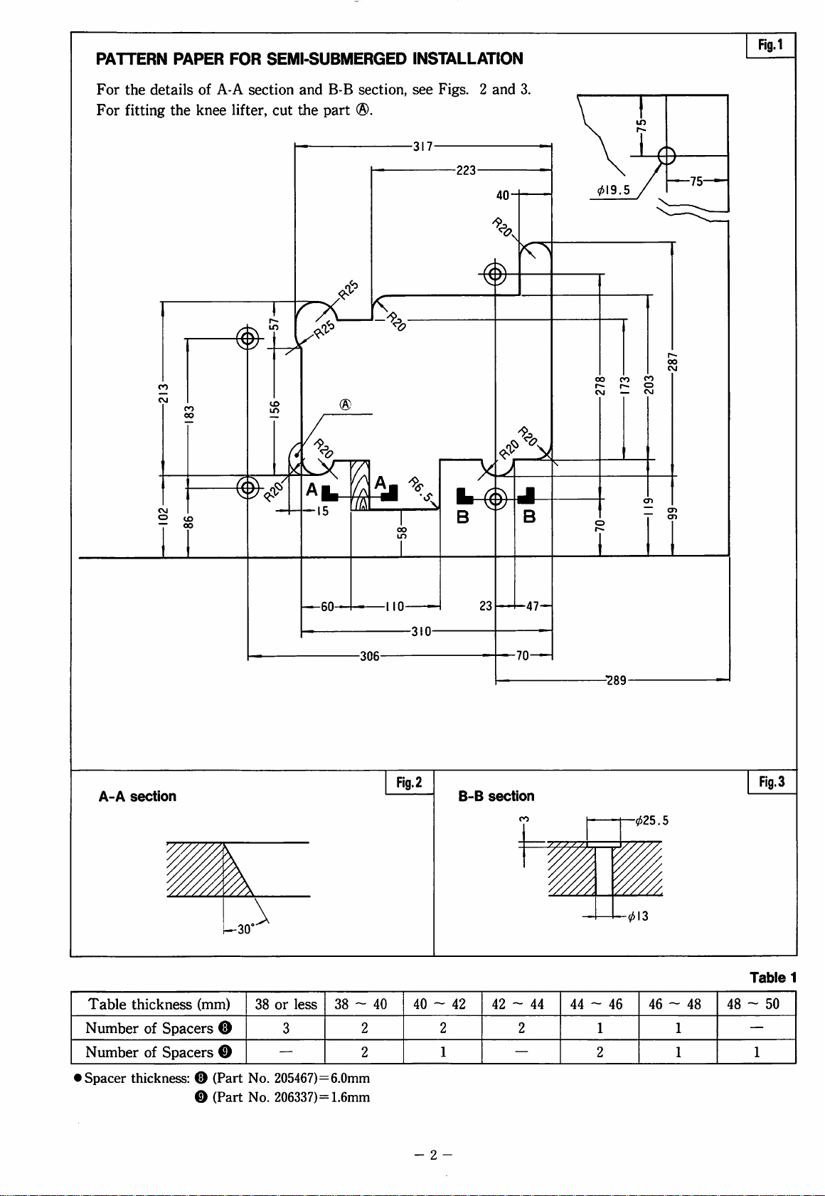
PATTERN
For
the
For
fitting
PAPER
details
the
of
knee
FOR
A-A
section
lifter,
SEMI-SUBMERGED
and
B-B
section,
cut
the
part
®.
INSTALLATION
see
Figs. 2 and
Fig.l
3.
A-A
section
A.
Flg.2
B-B
section
CO
Fig.3
-025.5
Table
Number
Number
•
Spacer
thickness
of
of
(mm)
Spacers
Spacers
®
@
thickness: ® (Part
0
(Part
38
or
less
3
—
No.
205467)=6.0mm
No.
206337)=1.6mm
38 ~ 40
2
2
40 ~ 42
2
1
-
2
42 ~ 44
—
■013
Table
1
44 ~ 46
2
1
2
46 ~ 48
1
1
48 ~ 50
—
1
Page 5

ASSEMBUNG
The
semi-submerged
for
this
machine.
board
and
the
manner.
1.
Refer
to
Fig.l
2.
Refer
to
Figs.4
rest
board
of O —
3.
Refer
lifter
®.
to
Fig.6
in
sequence
THE
MACHINE
Assemble
presser
and
cut
and
and
the
and
®
REST
installation
the
machine
foot
lifter
in
the
the
table
as
5.
Assemble
waste
assemble
chute
the
BOARD
is
standard
rest
following
specified.
the
machine
in
sequence
presser
foot
Fig.
4
^Note:
1.
For
thickness
2.
Install
top
Use
height
ETS
surface
45mm
the
series
or
machine
is
about
machine, a table
more
so
that
10cm
Spacers O and O to
of
the
machine
as
is
recommended.
the
needle
above
obtain
guided
the
in
plate
the
table.
correct
Table
of
1.
FI9.5
- 3 -
Fig.6
Page 6
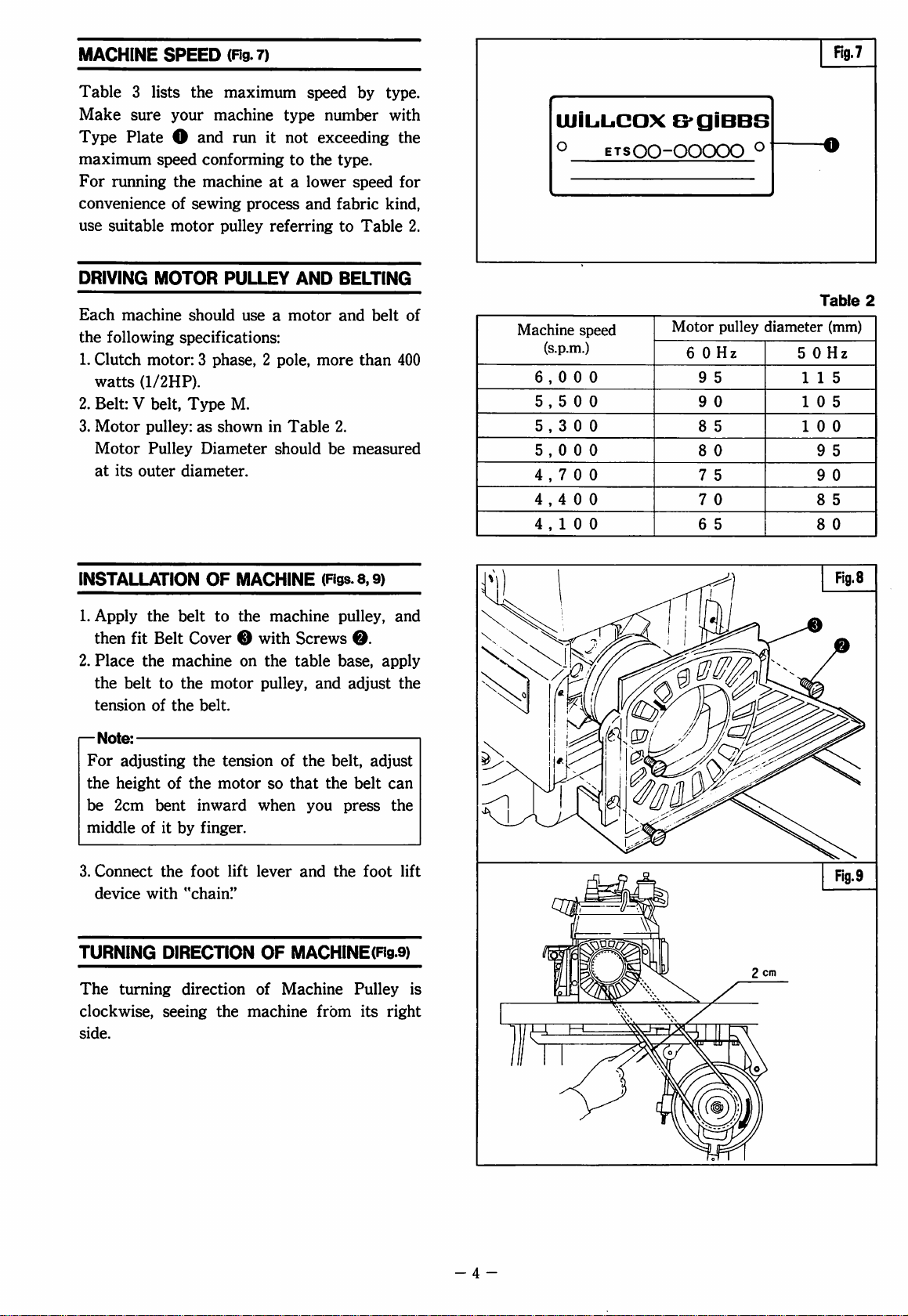
MACHINE
SPEED
(Fig.
7)
Rg.7
Table 3 lists
Make
Type
sure
Plate O and
maximum
For
running
convenience
use
suitable
DRIVING
Each
machine
the
following
1.
Clutch
watts
(1/2HP).
2.
Belt: V belt.
3.
Motor
Motor
at
its
outer
the
your
speed
the
of
sewing
motor
MOTOR
should
specifications:
motor: 3 phase, 2 pole,
Type
pulley:
Pulley
diameter.
maximum
machine
run
it
conforming
machine
at a lower
process
pulley
referring
PULLEY
use a motor
M.
as
shown
Diameter
in
should
speed
type
number
not
exceeding
to
the
type.
and
fabric
AND
more
Table
2,
be
by
type.
with
the
speed
for
kind,
to
Table
2.
BELTINg"
and
belt
of
than
400
measured
UJILiL.CaX
o
Machine
speed
(s.p.m.)
6,000
5,500
5,300
5,000
4,700
4,400
4,100
G'giBBS
ETSOO-OOOOO
Motor
6 0 Hz
9
5
9
0
8
5
8
0
7
5
7
0
6
5
o
pulley
Table
diameter
(mm)
5 0 Hz
115
10
10
9
9
8
8
2
5
0
5
0
5
0
INSTALLATION
1.
Apply
then
2.
Place
the
tension
i—
Note:
For
the
be
middle
3.
Connect
device
TURNING
The
clockwise,
side.
the
belt
fit
Belt
the
machine
belt
to
the
of
the
adjusting
height
2cm
of
bent
of
it
by
the
with
DIRECTION
turning
seeing
OF
MACHINE
to
the
machine
Cover 0 with
on
the
motor
belt.
the
the
inward
pulley,
tension
motor
so
when
finger.
foot
lift
lever
"chaini'
OF
direction
the
of
machine
(Rgs.8,9)
pulley,
Screws
table
of
the
that
and
MACHINE(Fig.9)
Machine
and
belt,
the
you
the
from
0.
base,
adjust
adjust
belt
press
foot
Pulley
its
and
apply
the
can
the
lift
is
right
Fig.9
-4-
Page 7

MAXIMUM
SPEED-FRONT
TOP
FEED
ETS52
Table
3
EXTRA-HIGH
(GENERAL
O
504-ETS52-141FA2/463W
O
514-ETS52-142FA2/463W
O
512-ETS52-142F
•
504-ETS52-141FA3/463W
•
514-ETS52-142F
•
512-ETS52-142FA3/463W
(GATHERING
OS
14-ETSS2-243FD2/463W/KL100
0
512-ETS52-243FD2/463W/KL100
•
514-ETS52-243FD3/463W/KL100
•
512-ETS52-243FD3/463W/KL100
(
PIPING
O504-ETS52-350FC2/p^/453W
O
514-ETS52-351
O
512-ETS52-351
SEAMINO)^^^^
Machine
Machine
Machine
type/spec.
A2/463W
A3/463W
)
type/spec.
3
type/spec.
FC2/^^/453W
FC2/^^/453W
UFT
Maximum
Maximum
Maximum
speed
(s.p.m.)
6,000
n
n
tt
ft
tt
speed
(s.p.m.)
5,500
tt
tt
tt
speed
(s.p.m.)
6,000
tt
tt
Machine
O504-ETS52-I30FA2/363N
0514-ETS52-133F
05I2-ETS52-I33FA2/363N
•
504-ETS52-130F
•
514-ETS52-133F
•
512-ETS52-133FA3/363N
Machine
O
514-ETS52-245FD2/363W/KL100
OS
12-ETS52-245FD2/363W/KL100
•
514-ETS52-245FD3/363W/KL100
•
512-ETS52-245FD3/363W/KL100
Machine
type/spec.
A2/363N
A3/363N
A3/363N
type/spec.
type/spec.
HIGH
UFT
05l4-ETS52-352FC2/^^/353W
05l2-ETS52-352FC2/^^/353W
Maximum
(s.p.m.)
6,000
Maximum
(s.p.m.)
5,500
Maximum
(8.p.m.)
6,000
speed
tt
tt
tt
tt
tt
speed
tt
tt
tt
speed
;/
(seaming/heavy)
Machine
O
514-ETS52-142FB2/|^/463W/K
O
512-ETS52-142FB2/|^/463W/KLI00
O
514-ETS52-253FB2/|2/493W/KL
O
512-ETS52-253F
O
514-ETS52-253FB2K/|2/493W/KLI00
O
512-ETS52-253F
(
BACK-LATCHING
Machine
0
514-ETS52-184FB2/443W/BT152
MAXIMUM
(GENERAL
Machine
0
504-ETS52-141B
OS
14-ETS52-142BA2/463W
0
512-ET
type/spec.
B2/|2/493W/KL
B2K/I2/493W/KL100
type/spec.
SEAMING)
type/spec.
A2/463W
S52-142B
A2/463W
L100
100
100
)
SPEED-REAR
Maximum
(8.p.m.)
5,000
Maximum
(s.p.m.)
5,000
Maximum
(s.p.m.)
6,000
speed
tt
tt
tt
tt
tt
speed
TOP
speed
tt
tt
(
BUND-HEMMING
Machine
•
505-ETS52-210FE3/323N
FEED
ETS52
type/spec.
)
Maximum
(s.p.m.)
6,000
speed
(PIPING
Machine
0
504-ET
S52-350BC2/^^
0
514-ETS52-351
OS
12-ETS52-351
type/spec.
BC2/^^/453W
BC2/^^/453W
)
/453W
Maximum
(s.p.m.)
6,000
speed
tt
tt
- 5 -
0 = Normal
• = Narrow
presser
presser
foot
foot
Page 8

LUBRICATION
The
oil
was
shipped.
starting
So,
it
for
drained
fill
the
the
first
from
the
machine
time.
machine
with
oil
when
before
lULAibricating
Use
Mobil
equivalent.
(UTo
fill
Take
out
head
of
upper
line
Replace
noil
level
Always
Indicator o is
Window
SI
Manual
Before
the
starting
machine
weeks,
Upper
Looper
Oil
Velocite
oil
(Rg.lO)
Screw O and
Oil
Level
'H'
of
Screw
keep
O.
(Rg.iO)
enough
between
©.
oiling
(Rgs.ii,i2,i3)
macnine
is
idle
manually
Holder
oil
No.
10
pour
Indicator
Oil
Level
Sight
oil
in
the
two
for
the
for
more
lubricate
hole
®.
(ISO
VG
22)
or
fresh
oil
until
the
reaches
Window
machine
so
the
O.
that
lines H and L of
first
time,
or
than a couple
O,
hole 0 and
of
if
^
Note:
On
every
morning
noil
circulation
Oil
Monitor O turns
run
the
machine.
If
it
keeps
and
check
oil
filter
noil
Change
After
[TlTo
Take
red,
if
is
clogged.
Change
oil
after
that,
change
drain
oil
out
Screw ® and
check
stop
the
oil
the
oil
(Rg.l4)
start,
lubricate
(Rg.iO)
green
from
the
machine
level
is
correct
first I month
every 6 months.
drain
oil
hole
O.
red
when
you
immediately
and
if
the
in
operation.
from
here.
Fig.
14
- 6 -
30kQ-cm
Page 9
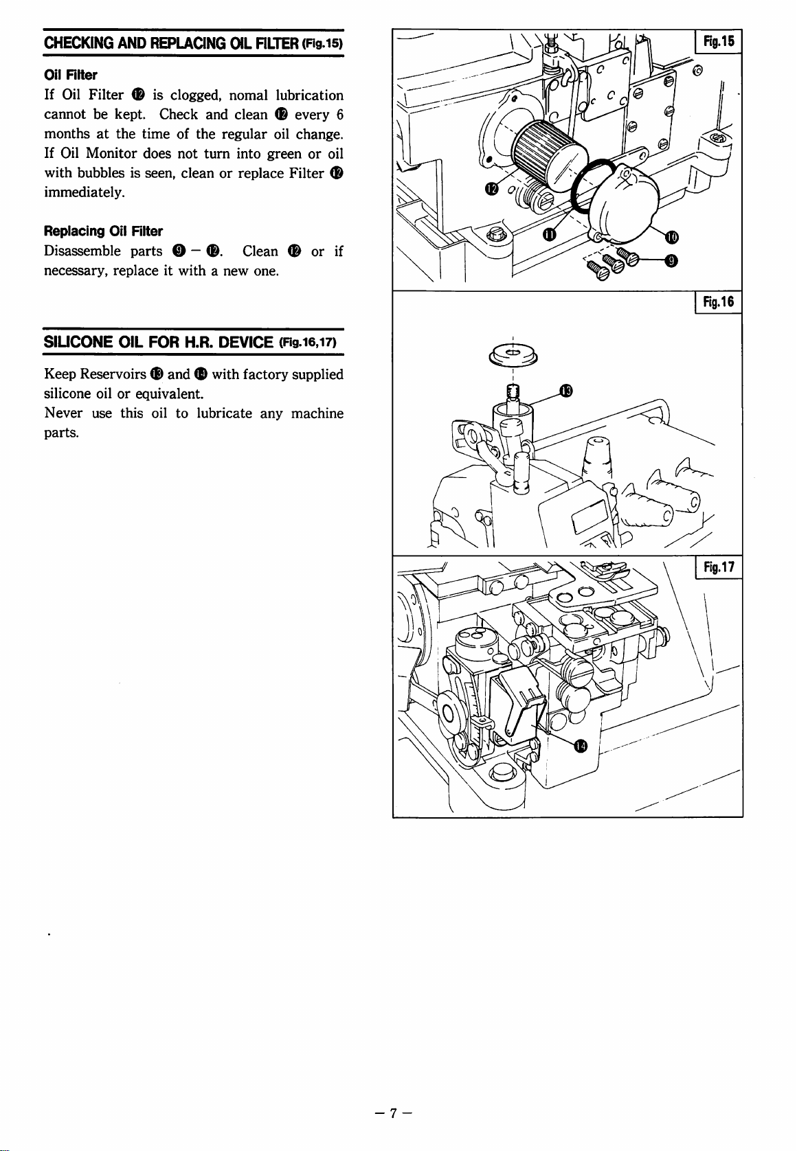
CHECKING
Oil
RIter
If
Oil
cannot
months
If
Oil
with
immediately.
AND
Filter
be
kept.
at
the
Monitor
bubbles
is
REPUONG
is
clogged,
Check
time
of
does
not
seen,
clean
OiL
RLTER
nomal
and
clean ® every
the
regular
turn
into
or
replace
(ng.i5)
lubrication
6
oil
change.
green
or
oil
Filter
®
Replacing
Disassemble
necessary,
SlUCONE
Keep
silicone
Never
parts.
Oil
RIter
parts
replace
OIL
Reservoirs ® and
oil
or
use
this
®
it
with a new
FOR
H.R.
(D
equivalent.
oil
to
lubricate
Clean ® or
one.
DEVICE
with
factory
any
if
(Rg.i6,i7)
supplied
machine
- 7 -
Page 10
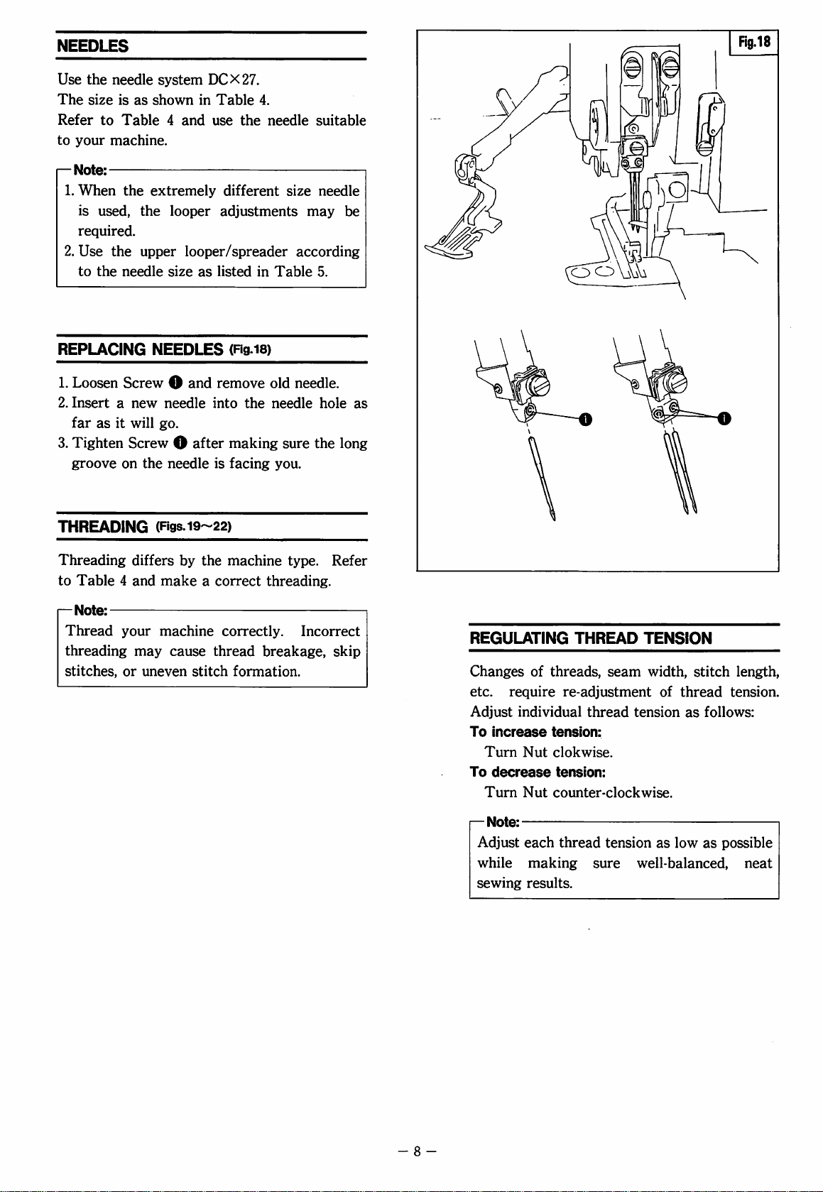
NEEDLES
Use
the
needle
The
size
is
Refer
to
Table 4 and
to
your
machine.
^
Note:
1.
When
is
required.
2.
Use
to
the
used,
the
the
needle
system
as
shown
extremely
the
looper
upper
looper/spreader
size
DCX27.
in
Table
use
the
4.
needle
different
adjustments
as
listed
in
suitable
size
needle
may
according
Table
5.
be
REPLACING
1.
Loosen
2.
Insert a new
far
as
3.
Tighten
groove
THREADING
Threading
to
Table 4 and
1—
Note:
Thread
threading
stitches,
NEEDLES
Screw O and
needle
it
will
go.
Screw O after
on
the
needle
(Figs.i9~22)
differs
make a correct
your
machine
may
or
uneven
by
the
cause
stitch
(ng.i8)
remove
into
is
correctly.
thread
old
the
needle
making
facing
sure
you.
machine
threading.
breakage,
formation.
needle.
hole
the
long
type.
Refer
Incorrect
skip
as
REGULATING
Changes
etc.
Adjust
To
Turn
To
Turn
of
require
individual
increase
Nut
decrease
Nut
THREAD
threads,
re-adjustment
thread
tension:
clokwise.
tension:
counter-clockwise.
TENSION
seam
tension
width,
of
thread
as
stitch
length,
tension.
follows:
[—
Note:
Adjust
while
sewing
- 8 -
each
thread
making
results.
tension
sure
well-balanced,
as
low
as
possible
neat
Page 11

NEEDLE
SIZE
AND
THREADING-FRONT
TOP
FEED
ETS52
Table
4
EXTRA-HIGH
(GENERAL
O
504-ETS52-141FA2/463W
O
514-ETS52-142FA2/463W
O
512-ETS52-142F
•
504-ETS52-141FA3/463W
•
514-ET
•
512-ETS52-142F
(GATHERING
O
514-ET
O
512-ET
•
514-ET
•
512-ETS52-243FD3/463W/KL100
SEAMING)
Machine
Machine
S52-142F
S52-243F
S52-243F
S52-243F
type/spec.
A2/463W
A3/463W
A3/463W
type/spec.
D2/463W/
D2/463W/
D3/463W/
)
KL100
KL
100
KL
100
(piping
Machine
O504-ETS52-350FC2/^^/453W
O
514-ETS52-351
0512-ETS52-351
type/spec.
FC2/p2/453W
FC2/^^/453W
LIFT
Needle
#1
Needle
#1
Needle
#1
HIGH
size
1
n
n
n
n
$t
size
1
H
tt
tt
size
1
tt
tt
Threading
Fig.
2!
Fig.
19
"
Fig.2l
Fig.
19
n
Threading
Fig.
19
tt
tt
tt
Threading
Fig.2l
Fig.
19
tt
Machine
O504-ETS52-I30FA2/363N
05I4-ETS52-I33FA2/363N
0512-ETS52-133F
•
504-ETS52-I30FA3/363N
•
514-ETS52-133F
•
512-ETS52-133FA3/363N
Machine
O
514-ETS52-245FD2/363W/KL100
O
512-ETS52-245FD2/363W/KL100
•
514-ETS52-245FD3/363W/KL100
•
512-ETS52-245FD3/363W/KL100
Machine
type/spec.
A2/363N
A3/363N
type/spec.
type/spec.
05l4-ETS52-352FC2/^^/353W
O
512-ETS52-352FC2/^^/353W
UFT
Needle
size
#1
1
//
n
tt
n
a
Needle
size
#1
!
tt
tt tt
tt
Needle
size
#1
!
tt tt
Threading
Fig.
22
Fig.
20
Fig.
22
Fig.
20
tt
Threading
Fig.
20
tt
tt
Threading
Fig.
20
(SEAMING/HEAVY
Machine
O5l4-ETS52-I42FB2/|^/463W/KLIOO
0
512-ETS52-142FB2/|2/463W/KLI
O
514-ETS52-253FB2/|^/493W/KLI
O
512-ETS52-253FB2/|^/493W/KLI
O
514-ETS52-253FB2K/I2/493W/KLI00
O
512-ETS52-253FB2K/|^/493W/KLI00
type/spec.
(BACK-LATCHING
Machine
0
514-ET
NEEDLE
(GENERAL
Machine
O
504-ETS52-141B
O
514-ETS52-142B
O
512-ETS52-142B
type/spec.
S52-184FB2/443W/BT152
SIZE
SEAMING)
type/spec.
A2/463W
A2/463W
A2/463W
)
CO
CO
CO
)
AND
Needle
#1
«
tt
tt
tt
tt
Needle
#1
THREADING-REAR
Needle
#1
tt
tt
size
!
size
!
size
1
Threading
Fig.
19
tt
tt
tt
tt
tt
Threading
Fig.
19
Threading
Fig.2l
Fig.
19
tt
(BUND-HEMMING
Machine
•I505-ETS52-210FE3/323N
type/spec.
TOP
)
FEED
Needle
#1
!
ETS52
size
Threading
Fig.
22
(PIPING
Machine
O504-ETS52-350BC2/^^/453W
O
514-ETS52-351
05l2-ETS52-35IBC2/p2/453W
type/spec.
BC2/p2/453W
)
Needle
#1
size
1
tt
tt
Threading
Fig.
2!
Fig.
19
tt
-
9
0 = Normal
• = Narrow
presser
foot
presser
foot
Page 12
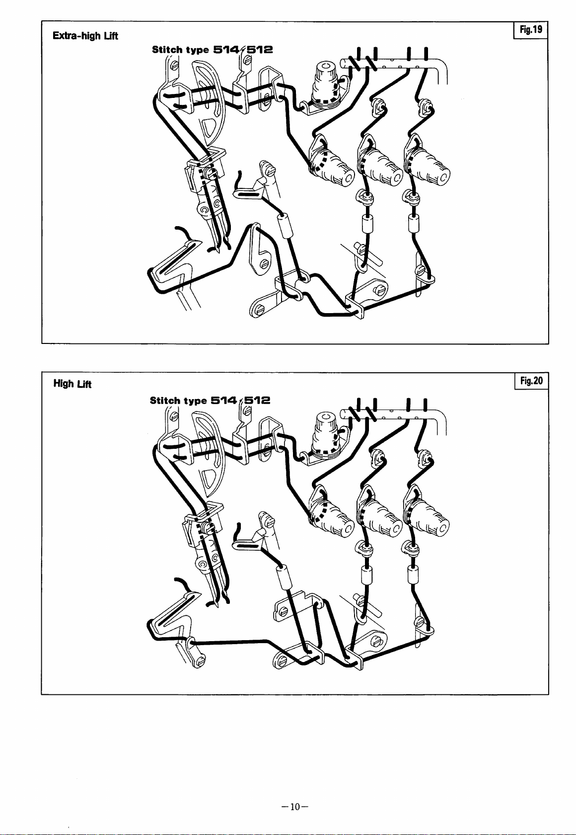
Extra-high
Lift
Stitch
type
Sl^fSlS
IJ
.
1
Rg.19
1
High
Lift
Stitch
type
i
IJ
.
1
Fig.20
1
-10-
Page 13

Extra-high
Lift
Stitch
type
SO
Fig.21
4
i
ll
High
Lift
Stitch
type
504/>505
I
Fig.22
II
-11-
Page 14
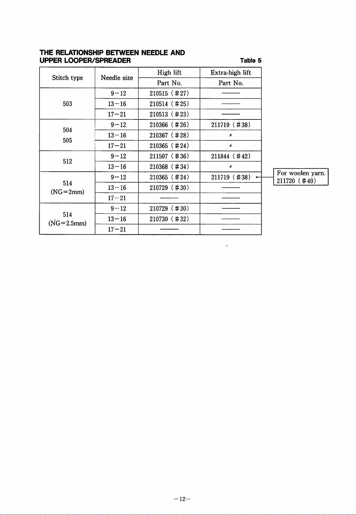
THE
RELATIONSHIP
UPPER
Stitch
(NG=2mm)
(NG=2.5mm)
BETWEEN
LOOPER/SPREADER
type
503
504
505
512
514
514
Needle
9-12
13-16
17-21
9-12
13-16
17-21
9-12
13-16
9-12
13-16
17-21
9-12
13-16
17-21
size
NEEDLE
High
Part
210515
210514
210513
210366
210367
210365
211507
210368
210365
210729
210729
210730
AND
lift
No.
(#27)
(#25)
(#23)
(#26)
(#28)
(#24)
(#36)
(#34)
(#24)
(#30)
(#30)
(#32)
Table
Extra-high
Part
211719
211844
211719
lift
No.
(#38)
(#42)
(#38)
5
For
woolen
211720
yarn.
(#40)
-12-
Page 15

PRESSER
When
arm,
Swinging-out
Open
the
only
this
Presser
Swinging-in
Press
ARM
Swinging-in
first
raise
Spring 0 in
foot
lifting
the
top
feed
position,
Arm O to
the
foot
Lever 0 and
Keeping
return
-Note:
Rear
CBC2]
Raise
you
Arm
this
Presser
Top
Feed
in
the
the
needle
can
swing-in
O.
SWINGING-IN
or
swinging-out
the
needle
the
arrowed
treadle
dog
will
pull
up
Lever O and
the
left.
lifting
the
treadle
top
feed
position,
Arm O to
Machines
last 3 figures
to
the
or
AND
to
the
or
lower
be
or
dog
pull
up
the
shown
of
highest
swing
-0UT(Fig.23)
the
presser
highest
direction,
position.
press
Lever 0 and
raised.
Keeping
swing-out
lower
will
be
Foot
raised.
Lever O and
original
Type
position.
as
CBA2]
Plate:
position
out
Presser
Lift
or
and
PRESSER
To
adjust
Presser
possible,
and
foot
while
obtain
FOOT
the
pressure,
pressure
still
proper
stitch
PRESSURE
turn
should
sufficient
formation.
(Rg.24)
Screw
be
to
0.
as
light
feed
Fig.24
as
fabric
-13-
Page 16

STITCH
LENGTH ADJUSTMENT
(Fi98.25.26)
While
0
Turn 0 further
Release
For a longer
direction.
For a shorter
direction.
^
MAIN
HANDWHEEL
pressing
until
Button O drops
Push
O.
stitch
stitch
Note:
The
stitch
nominal.
length
Table 6 shows
scale
setting.
an
approximate
FEED
STROKE
SCALE
Handwheel
scale
setting
Main
feed
stroke
(mm)
1
1.0
(0.6)
C0.8)
Button
for a desired
length,
length,
is
the
this
stroke
It
may
stitch
(mm)
SETTING
2
1.5
(0.9)
C1.3)
• ( )=ETS52-142FB2,
• C :i=FTS52-253FB2.
O,
turn
Handwheel
in.
stitch
turn 0 in
turn 0 in
main
feed
stroke
by
the
handwheel
be a reference
length.
BY
THE
3
4
2.0
2.5
(1.2)
(1.5) (1.9)
(1.7)
[2.1]
-184FB2.
5
3.0
[2.5]
to
(2.2)
[3.0]
length.
the
{+)
the
(—)
in
know
Table
6
7
3.5
3.8
(2.35)
[3.2]
6
©
DIFFENTIAL
Loosen
To
direction.
To
direction.
—Note:
Nut
0.
gather
stretch
the
the
Table 7 shows
the
lever
setting.
When
differential
•
Lever 0 is
If
set
feed
higher
differential
Maximum
•
If
set
lower
feed
is
applied.
Maximum
FEED
fabric,
ADJUSTMENT
turn
fabric,
turn
the
differential
set
ratio
than
feed
is
applied.
up
to 1 I
than
(2),
up
to 1 I
Screw O in
Screw O in
to
the
is 1 I
1.
(2),
0.7.
the
positive
2.
(Fig.27)
the
(+)
the
(—)
feed
ratio
by
scale
(2),
the
the
negative
differential
DIFFERENTIAL
Scale
on
indication
Differential
feed
ratio
( )=ETS52-142FB2,
C )=ETS52-253FB2.
FEED
the
plate
1:0.7
(1:1.1)
[1:0.8]
RATIO
1
(1:1.6)
[1:1.2]
-184FB2.
2
1:1
3
1:1.4
(1:2.2)
[1:1.7]
4
1:1.7
(1:2.7)
[1:2]
Table
5
1:2
(1:3.2)
[1:2.4]
7
6
[1:2.8]
-14-
Page 17

TOP
FEED
STROKE
ADJUSTMENT
(Fig.28)
Loosen
stroke
Nut ® shift
will
Shift O in
will
increase.
Shift O in
will
decrease.
•
When
will
•
When
depending
ADJUSTING
For
Loosen
top
-
•
•
•
seaming,
not
standard
Nut
feed
pressure
Notes:
Too
much
on
the
fabric.
Too
little
the
top
abnormal
Adjust
while
positive
Lever O and
be
changed.
the
(+)
direction,
the
(—)
direction,
adjust
occur.
shirring/adding
on
the
TOP
pressure
®,
turn
on
pressure
pressure
feed
noise.
the
pressure
feeding
so
that
fullness,
nature
FEED
of
PRESSURE
set
gap
the
Screw ® and
the
fabric.
may
cause
may
cause
dog,
uneven
as
weak
should
the
and
and
the
fabrics.
(a)
to
feed
jumping
feeding
as
be
top
the
stroke
the
stroke
ply
adjust
(Fig.29)
25mm.
adjust
marking
possible
kept.
feed
shift
Flg.29
the
of
or
-15-
Page 18

REGULATING
1.
Loosen
O
2.
Loosen
Screw
to
the
Screw O and
Clamp 0 to
seam
width
Tighten
3.
Turn
Knife
Plate
will
4.
Make
Tighten
5.
Check
thread
check
^
Note:
Needle
available.
of
width
CHANGING
Screw
Handwheel
is
top.
return
sure
Screw
Knives
between
the
Plates
the
proper
required.
SEAM
0,
left
and
the
is
obtained.
O.
about
1.0mm
Loosen
to
position.
Knives
0.
cut
Knives,
cutting
for
Best
results
size
UPPER
WIDTH
push
Lower
lightly
tighten
move
right
or
left
so
that
above
Screw
are
sharply;
of
various
0,
in a perfect
turn
knives.
are
Needle
KNIFE
(Rgs.30,3i)
Knife
Holder
Screw
Upper
Knife
until a desired
the
point
'b'
from
then
insert a piece
Handwheel
seam
obtained
Plate
(Figs.3i~33)
Needle
Holder
alignment.
widths
with
for
seam
©.
are
use
of
O
of
and
1
.0"""
1
I /
11/
Rg.31
Needle
/
top
plate
surface
/
1.
Loosen
O
2.
Remove
Replace
to
Screw
the
left
Screw
Upper
Adjust © so
for
the
seam
Upper
when © is
3.
Turn
is
Loosen
to
Make
Tighten
4.
Check
thread
check
CHANGING
1.
Loosen
O
2.
Loosen
Replace
Move
is
Tighten
3.
Turn
Upper
Needle
and
Handwheel
about
1.0mm
Screw
position.
sure
Screw
Knives
between
the
cutting
Screw
to
the
left,
Screw
Lower
Knife
level
with
Screw
Handwheel
Knife
Plate
lowest.
Knives
LOWER
up
Holder O will
4.
Make
sure
Knives
Tighten
5.
Check
thread
check
Screw
Knives
between
the
cutting
0,
push
Lower
and
lightly
©.
Knife © with
that
it
is
in
width
and
Lower
so
above
0,
then
are
Knives
that
from
Holder O will
in a perfect
0.
cut
sharp;
Knives,
of
Knives.
turn
KNIFE
0,
push
Lower
and
lightly
0.
Knife © with
or
down
until
Needle
Plate
©.
so
that
is
about
top.
Loosen
return
0.
to
are
in a perfect
cut
sharp;
Knives,
of
knives.
turn
Knife
tighten
the
the
correct
also,
the
is
the
point
Needle
Holder
Screw
0.
new
one.
position
overlap
0.5 — 1.0mm
'b'
of
Knife
Plate
top.
return
of
alignment.
insert a piece
Handwheel
(Figs.3i~33)
Knife
tighten
top.
1.0mm
the
its
cutting
the
point
above
Screw
Screw
new
0,
of
and
~
Holder
0.
one.
edge
'b'
of
from
then
position.
alignment.
insert a piece
Handwheel
of
and
16-
Upper
knife
0.5~ I .Omin
Lower
knife
Needle
top
surface
Fig.32
plate
Page 19

REGULATING
(ANGLED
1.
Loosen
O
2.
Loosen
to
the
UPPER
Screw
left
Screw
Holder O to
seam
width
Tighten
3.
Turn
Knife
Plate
will
4.
Make
Tighten
Check
thread
check
Screw
Handwheel
is
about
top.
return
sure
Screw
Knives
between
the
SEAM
KNIFE)
©,
and
lightly
(E)
the
right
is
obtained.
(E).
1.0mm
Loosen
to
position.
Knives
©.
cut
Knives,
cutting
of
WIDTH
push
Lower
tighten
and
move
or
left
so
that
the
above
Screw
are
sharply;
©,
'
in a perfect
insert a piece
turn
knives.
(Figs.34,35)
Knife
Holder
Screw
Upper
0.
Knife
until a desired
point
'b'
of
from
Needle
then
Holder
alignment.
Handwheel
O
of
and
Flg.34
Fig.35
CHANGING
(ANGLED
1.
Loosen
O
2.
Loosen
Knife
to
the
0.
UPPER
Screw
Screws
Adjust 0 so
for
the
seam
Upper
when 0 is
3.
Turn
Knife
Plate
Loosen
to
Make
Tighten
4.
Check
thread
check
and
Handwheel
is
top.
Screw
position.
sure
Screw
Knives
between
the
UPPER
KNIFE)
0,
left
and
0, 0 and
that
width
Lower
lowest.
about
cutting
1.0mm
0,
Knives
0.
cut
Knives,
KNIFE
push
lightly
it
is
and
so
then
are
sharp;
of
(Rgs.34-36)
Lower
tighten
in
the
also,
Knives
that
above
Holder O will
in a perfect
insert a piece
turn
Knives.
Knife
Screw
replace
correct
the
overlap
is
0.5 — 1.0mm
the
point
from
alignment.
Handwheel
Holder
0.
Upper
position
of
'b'
of
Needle
return
of
and
0.5~ I .Omm
top
Lower
knife
Needle
surface
Fig.36
plate
KNIVES
Knives
If
the
sharpen
Sharpening
Sharpen
Upper
Upper
returned
special
(Rg.37)
must
be
machine
the
lower
Lower
Lower
Knife
Knife
may
to
us
for
grinding.
kept
sharp.
does
not
trim
knife.
Knife
0
Knife © as
be
sent
to
resharpening
the
fabric
specified
our
since
sharply,
in
distributors
it
requires
Fig.
37.
or
-17-
Part
No.
202295
Part
87'
No.
Fig.37
62'
201127
Page 20

NEEDLE
The
guides
Refer
positions
For
adjust
THREAD
standard
O,
to
Table 8 and
to
adjusting,
Guides
GUIDE
SETTING
setting
positions
0, ® are
set
your
machine.
loosen
O,
0,
0.
POSITION
of
as
shown
them
Screws
needle
in
to
the
O,
0, 0 and
(Rg.38)
thread
Table
correct
Fig.38
8.
LOOPER
THREAD
Check
for
the
the
high
Extra-high
1.
Looper
Loosen
lowest
THREAD
GUIDE
your
machine
extra-high
lift
machines.
Lift
(Fig.
Thread
Screw 0 and
position.
When a woolen
highest
2.
Upper
Lower
When
point,
Guides
position
position.
Looper
Looper
the
lower
loosen
0, 0 up
shown
When a woolen
in
Fig.
39.
3.
Looper
For
514,
to
respectively.
For
0
4.
Looper
Loosen
position
Thread
the
machines
loosen
the
the
to
Screw 0 and
positions
machines
(512).
Thread
Screw 0 and
as
indicated
TAKEUP
SETTING
with
lift
machines.
39)
Guide
0
yarn
Thread
Thread
Screws
Takeup
looper
and
in
Fig.
yarn
is
Guide
0
of
the
indicated
of
the
Guide
0
in
AND
POSITIONS
Table
set
Guide 0 to
is
used,
0,
Takeup
is
0
at
0, 0,
down
39.
used,
set 0 to
stitch
set
Thread
as
stitch
set
Guide 0 to
Fig.
39.
LOOPER
8.
See
See
Fig.
set 0 to
the
right
shift
Thread
and
set
(36mm)
types
504
Guide
(504)
and
type
512,
Fig.
40
for
the
the
dead
to
the
and
0
(514)
set
the
39
A = Highest
B = Center
C = Lowest
High
Lift
(Fig.40)
1.
Looper
Loosen
between
Thread
2.
Upper
Lower
When
point,
Thread
Guide 0 is
Looper
Looper
the
loosen
Takeups
position
3.
Looper
For
and
the
respectively.
For
0
4.
Looper
Loosen
position
Thread
the
514,
positions
the
to
(512).
Thread
Screw 0 and
Guide
0
Screw 0 and
Bed
(a)
surface
39.0mm.
Thread
Thread
lower
Takeup
Takeup
looper
Screws
0, 0 up
as
shown
machines
loosen
indicated
machines
as
indicated
and
in
Fig.
Guide
0
of
the
Screw 0 and
of
the
Guide
0
in
set
that
and
is
at
0,
0,
down,
40.
stitch
as
(504),
stitch
set
Guide 0 to
Fig.
40.
the
the
0,
0
the
right
adjust
and
set
types
set
Guide 0 to
(505)
and
type
distance
hole
of
dead
Thread
at
the
504,
505
(514)
512,
set
the
504,
yarn
514
-0-
0
-18-
High
0
Lift
0
Extra-high
Lift
Woolen
0
yam
Woolen
504,
505,
514
Page 21

NEEDLE
THREAD
GUIDE
SETTING
POSITION-FRONT
TOP
FEED
ETS52
Tables
EXTRA-HIGH
(GENERAL
O
504-ETS52-141F
O
514-ETS52-142F
O
512-ETS52-142F
•
504-ETS52-141F
•
514-ETS52-142F
•
512-ETS52-142F
(GATHERING
O
514-ETS52-243FD2/463W/KL100
O
512-ET
•
514-ETS52-243FD3/463W/KL100
•
512-ETS52-243FD3/463W/KL100
SEAMING)
Machine
Machine
S52-243FD2/463W/KL100
type/spec.
A2/463W
A2/463W
A2/463W
A3/463W
A3/463W
A3/463W
type/spec.
)
(piping
Machine
O504-ETS52-350FC2/^^/453W
O
514-ETS52-351
O
512-ETS52-351
type/spec.
FC2/p2/453W
FC2/^^/453W
UFT
Setting
Setting
position
o
B
tt
ft
tt
tt
tt
position
&
B
tt
"
position
e
B
//
"
O
B
n
n
«
tr
tf
O
B
tt
tt tt tt
tt
Setting
O
B
"
«
&
B
0
ft
O
O
"
•
tf
•
tt
•
e
B
O
tt
O5I2-ETS52-245FD2/363W/KLI00
•
tt
•
&
B
O
"
tt
O
Machine
504-ETS52-130F
514-ETS52-133F
512-ETS52-133F
504-ETS52-130F
5I4-ETS52-I33FA3/363N
512-ET
S52-133F
Machine
514-ET
S52-245F
5I4-ETS52-245FD3/363W/KLI00
5I2-ETS52-245FD3/363W/KLI00
Machine
514-ET
S52-352FC2/^^
512-ETS52-352FC2/^^/353W
HIGH
type/spec.
A2/363N
A2/363N
A2/363N
A3/363N
A3/363N
type/spec.
D2/363W/
type/spec.
/353W
KL100
UFT
Setting
O
B
ft
tf
tt
ft
ft
Setting
O
B
tt
tt
tt
Setting
O
•
B
tt tt
position
e
c
tt
tt
tt tt
tt
tt
position
e
c
It
tt tt
It
position
e e
0
e
0
tt
tt
tt
tt
&
c
tt
"
c
(SEAMING/HEAVY
Machine
l5I4-ETS52-I42FB2/|^/463W/KLI00
O
512-ETS52-142F
O
514-ET
S52-253F
O
512-ET
S52-253F
; 5I4-ETS52-253FB2K/|^/493W/KLI0D
c:
512-ETS52-253FB2K/|^/493W/KL
type/spec.
B2/|^/463W/KL
B2/|^/493W/
B2/|2/493W/KLI
(BACK-LATCHING
Machine
O
514-ETS52-184FB2/443W/BT152
NEEDLE
(general
Machine
O
504-ETS52-141BA2/463W
O
514-ETS52-142BA2/463W
O
512-ETS52- i 42B
type/spec.
THREAD
seaming)
type/spec.
A2/463W
)
100
K
L100
00
100
)
GUIDE
Setting
O
B B
"
tt
tt
«
"
Setting
O
B B
Setting
O
B
tt
tt
position
O
B
tt tt
tt
"
tt
tt
position
&
tt
tt
tt
tt
&
B
SETTING
position
O
B
"
&
B
tt
"
(BUND-HEMMING
•
505-ET
Machine
S52-21
type/spec.
OF
E3/323N
)
POSITION-REAR
TOP
Setting
O
B
FEED
position
e
A
ETS52
e
A
(PIPING
Machine
O
504-ETS52-350BC2/^^/453W
O
514-ETS52-351
O
512-ETS52-351
type/spec.
BC2/p2/453W
BC2/^i/453W
)
Setting
O
B B
"
tt
position
e
tt
tt
&
B
tt
tt
-19-
0 = Normal
• = Narrow
presser
presser
foot
foot
Page 22

BOTTOM
FEED
HEIGHT
(Figs.4i,42)
Fig.41
Bottom
Table
to
1.Tum
2.
3.
feed
9.
Make
your
machine.
the
dog
to
the
Adjust
needle
of
the
For
Main
Set
gap
plate
the
main
type.
adjusting,
Feed
the
tooth
Dog 0 to
(c)
of
the
main
For
adjusting,
dog
handwheel
highest
Dog O up
the
Differential
height
sure
(a)
from
to
the
feed
dog
loosen
end
same
feed
loosen
Feed
by
type
that
the
setting
to
lift
position.
the
top
tooth
end
to
the
Screw O and
and
down.
(b)
of
Differential
height
dog.
Screw O and
Dog © up
is
as
the
bottom
face
of
the
height
as
the
and
correct
down.
shown
is
correct
feed
of
rear
part
shift
Feed
tooth
end
shift
in
the
to
(a)
(c)
(b)
AUXILIARY
Gap
(d)
dog
to
is
adjusted
Generally,
wider,
smaller.
To
adjust
Auxiliary
BOTTOM
fr-om
the
tooth
to
for
and
the
Feed
FEED
FEED
the
the
using
for
using
gap,
Dog © up
ADJUSTMENT
Adjust
the
appear.
For
Screw
so
that
all
needle
adjusting,
©,
plate
and
turn
remove
DOG
HEIGHT
tooth
end
of
the
end
of
Auxiliary
machine
loosen
LEVELING
type.
coarse
finer
thread,
thread,
Screw © and
and
down.
POSITION
(Rgs.44,45)
the
teeth
ends
are
top
surface
cover
Washer
when
plate
©
(Fig.43)
main
Feed
Dog
set
the
set
the
flush
they
©,
feed
©
gap
gap
shift
with
first
loosen
Fig.43
Fig.44
-Needle
top
surface
plate
^
Note:
1.
For
hold
so
2.
Be
after
tightening
the
as
to
avoid
sure
the
Screw © after
feed
bar
exactly
sidewise
to
adjust
adjustment.
"bottom
adjustment,
with
Washer
shifting.
feed
©
height"
-20-
Page 23

BOTTOM
FEED
HEIGHT-FRONT
TOP
FEED
ETS52
Table
9
EXTRA-HIGH
(GENERAL
O
504-ETS52-141F
0
514-ETS52-142F
O
512-ETS52-142F
•
504-ET
•
514-ETS52-142F
•
512-ETS52-142F
(GATHERING
O
514-ET
O
512-ET
•
514-ET
•
512-ETS52-243FD3/463W/KL100
(
PIPING
O504-ETS52-350FC2/p2/453W
SEAMING^^
Machine
Machine
Machine
S52-141F
S52-243F
S52-243F
S52-243F
type/spec.
A2/463W
A2/463W
A2/463W
A3/463W
A3/463W
A3/463W
)
type/spec.
D2/463W/KL100
D2/463W/KL100
D3/463W/KL100
)
type/spec.
05l4-ETS52-35IFC2/^i/453W
O
512-ETS52-351
FC2/^^/453W
UFT
Bottom
Bottom
Bottom
feed
0.9-1.1
n
n
n
tf
»
feed
0.9-1
.1
n
n
n
feed
0.9-1.1
tf
tf
height
height
height
Machine
O
504-ETS52-130F
O
514-ET
O
512-ET
•
504-ET
•
514-ETS52-133F
•
512-ETS52-133F
Machine
O
514-ETS52-245FD2/363W/KL100
O
512-ETS52-245FD2/363W/KL100
•
514-ETS52-245FD3/363W/KL100
•
512-ET
Machine
O
514-ET
S52-352FC2/p2
O
512-ET
S52-352FC2/^^
S52-133F
S52-133F
S52-130F
S52-245F
type/spec.
A2/363N
A2/363N
A2/363N
A3/363N
A3/363N
A3/363N
type/spec.
D3/363W/
type/spec.
/353W
/353W
HIGH
KL100
UFT
o
Bottom
0.8-1
Bottom
0.8-1
Bottom
7
00
feed
n
n
tt
n
H
feed
"
n
ft
feed
"
O
height
.0
height
.0
height
(
SEAMING/HEAVY
Machine
O
514-ET
O
512-ETS52-142F
type/spec.
S52-142F
B2/|2/463W/
B2/|^/463W/K
)
K
L100
L100
Bottom
O5l4-ETS52-253FB2/|i/493W/KLI00
O
512-ETS52-253F
B2/|2/493W/K
L100
C5I4-ETS52-253FB2K/|^/493W/KLIG0
O
51
2-ETS52-253FB2K/|2/493W/KLI
(
BACK-LATCHING
Machine
O
514-ETS52-184FB2/443W/BT152
BOTTOM
(GENERAL
Machine
O
504-ET
C
514-ETS52-142BA2/463W
0
512-ETS52-142B
type/spec.
FEED
SEAMING)
type/spec.
S52-141BA2/463W
A2/463W
CO
)
Bottom
HEIGHT-REAR
Bottom
feed
0.9-1.1
ft
ft
ft
ft
ft
feed
0.9-1
.1
feed
0.9-1
.1
tf
«
height
height
height
(
BLIND-HEMMING
•
505-ET
TOP
Machine
FEED
S52-21
type/spec.
OF
E3/323N
ETS52
)
Bottom
0.8-1
feed
height
.0
(piping
Machine
O
504-ET
S52-350BC2/p2/453W
C
514-ET
S52-351
O
512-ETS52-351
type/spec.
BC2/p2
BC2/p2/453W
/453W
()
Bottom
0.9-1.1
feed
ff
"
height
-21-
0 = Normal
• = Narrow
presser
presser
foot
foot
Page 24

NEEDLE
HEIGHT
SETTING
(Rgs.46,47)
Fig.46
Needle
Make
and
procedures.
1.
2.
In
that
needle
If
O
height
sure
set
to
Turn
the
the
highest
Measure
the
needle
and
adjust
dimension.
For
adjusting,
Needle
Note:
the
case
each
slot
not,
loosen
and
adjust.
Holder
of
gap
by
type
the
machine
the
correct
handwheel
level.
(a)
between
plate
top
the
needle
loosen
Guide
of
2-needle
needle
of
the
passes
needle
Screw
is
as
shown
type,
refer
height
and
surface
in
the
bring
the
the
needle
perpendicularly
height
to
Screw O and
©.
machines,
the
center
plate.
®,
turn
Needle
in
Table
to
Table
following
needle
point
the
correct
adjust
make
sure
of
the
Holder
10.
10,
to
and
Fig.47
LOWER
The
lower
Make
sure
and
set
in
1.
With
the
0 — 0.05mm
comes
In
for
For
to
the
case
both
adjusting,
Looper
2.
When
point,
and
the
adjust
the
dimension
In
the
the
left
For
adjusting,
Looper
LOOPER
looper
of
the
the
needle
the
needles.
SETTING
setting
machine
following
guard
bent
by
the
center
of
of
2-needle,
loosen
Holder 0 back
lower
needle
to
case
needle.
looper
gap
(b)
between
centerline
machine
of
2-needle,
loosen
Holder 0 to
the
(Figs.48.49)
is
as
shown
type,
in
refer
to
procedures.
idle,
set
the
looper
the
obtain
point
needle.
this
condition
Screw 0 and
and
forth.
is
at
the
left
the
looper
to
the
type.
check
gap
Screw 0 and
right
or
left.
Table
Table
needle
when
shift
dead
point
correct
(b)
with
shift
10.
10,
it
Fig.48
0 ~ 0.05n"n
Rg.49
22-
Page 25

NEEDLE
(GENERAL
O
504-ETS52-141FA2/463W
O
514-ET
05I2-ETS52-I42FA2/463W
•
504-ETS52-141F
•
514-ETS52-142F
•
512-ET
HEIGHT/LOWER
SEAMING)
Machine
type/spec.
S52-142F
S52-142F
A2/463W
A3/463W
A3/463W
A3/463W
EXTRA-HIGH
UFT
Needle
(a)
11.7-11.9
n
tf
if
"
LOOPER
Lower
looper
(b)
3.6-3.9
it
n
ft
ft
ft
SETTING-FRONT
HIGH
Machine
O
504-ETS52-130F
O
514-ETS52-133F
O
512-ETS52-133F
•
504-ETS52-130F
•
514-ET
•
5I2-ETS52-I33FA3/363N
S52-133F
type/spec.
A2/363N
A2/363N
A2/363N
A3/363N
A3/363N
TOP
UFT
FEED
Needle
(a)
10.4-10.6
ft
1 1
.3-11.5
10.4-10.6
tf tf
II.3-11.5
ETS52
Table
I
00
CO
i
Lower
looper
(b)
3.8-4.
ff
ft
tf
10
1
(GATHERING
Machine
O
514-ETS52-243FD2/463W/KL100
0512-ETS52-243FD2/463W/KL100
•
514-ETS52-243FD3/463W/KL100
•
512-ETS52-243FD3/463W/KL100
(
PIPING
Machine
O504-ETS52-350FC2/^^/453W
O
514-ETS52-351
O
512-ETS52-351
type/spec.
type/spec.
FC2/^^/453W
FC2/^^/453W
J
)
Needle
(a)
II.7-11.9
Needle
II.7-11.9
(seaming/heavy)
Machine
type/spec.
O5l4-ETS52-I42FB2/|^/463W/KLIOO
O
512-ET
S52-142F
O
5I4-ETS52-253FB2/|2/493W/KLI00
O
5I2-ETS52-253FB2/|^/493W/KLI00
O
514-ETS52-253F
B2/|2/463W/
K
L100
B2K/|^/493W/KL
O5l2-ETS52-253FB2K/|^/493W/KLIOO
Needle
II.7-11.9
100
"
(a)
"
"
(a)
"
"
Lower
looper
(b)
3.6-3.9
tf
tf
ft
tf
'■
OC
Lower
3.6-3.9
Lower
3.6-3.9
ft
"
"
/
DI
looper
(b)
//
tf
looper
(b)
ft
tf
tf
tf
If
CD
•
•
Machine
O
514-ETS52-245FD2/363W/KL100
O
512-ETS52-245FD2/363W/KL100
514-ETS52-245FD3/363W/KL100
512-ETS52-245FD3/363W/KL100
Machine
O
514-ETS52-352FC2/p2/353W
type/spec.
type/spec.
05l2-ETS52-352FC2/p^/353W
Needle
(a)
10.4-10.6
1 1
.3-11.5
10.4-10.6
1
1.3-11.5
Needle
(a)
10.4-10.6
I I
.3-11.5
Lower
Lower
3.8-4.
looper
(b)
tf
tf
tf
looper
(b)
ft
1
(
(
BACK-LATCHING
Machine
O
514-ET
NEEDLE
(GENERAL
Machine
O
504-ET
O
514-ETS52-142BA2/463W
O
512-ETS52-142BA2/463W
type/spec.
S52-184FB2/443W/BT152
HEIGHT/LOWER
SEAMING)
type/spec.
S52-141BA2/463W
Cpiping
Machine
O504-ETS52-350BC2/p2/453W
O
514-ET
O
512-ETS52-351
type/spec.
S52-351BC2/^^
/453W
BC2/^2/453W
)
Lower
Needle
I I
.7-11.9
(a)
(b)
3.6-3.9
looper
LOOPER
Lower
Needle
1 1
.7-11.9
(a)
"
ft
(b)
3.6-3.9
looper
It
"
)
Lower
Needle
I I
.7-11.9
(a)
»
ft
(b)
looper
BUND-HEMMING
•
505-ET
Machine
S52-21
type/spec.
OF
E3/323N
SETTING-REAR
-23-
)
TOP
Needle
(a)
10.4-10.6
FEED
0 = Normal
• = Narrow
Lower
looper
(b)
3.8-4.
ETS52
presser
presser
1
foot
foot
Page 26

UPPER
The
Make
machine.
1.
2.
•
3.
0.5mm.
(c)
LOOPER
standard
sure
Tentatively
Screw
0.
Fig.
50
or
When
adjust
Loosen
and
Figs.
In
the
When
check
Tighten
Figs.
the
gap
Screw
adjust
52
or
the
case
left
needle.
the
that
Turn
to
approximately
Screws 0 and
54
and
SETTING
setting
that
the
set
the
51.
Table
looper
(a)
to
0.
this.
53.
of
2-needle,
upper
clearance
the
55.
is
as
setting
looper
11.
is
at
the
correct
move
Crank O up
and
lower
(b)
looper
0.2mm.
0.
(Rgs
so-ss)
shown
is
the
check
and
in
correct
in
Holder O by
left
dimension.
gap
loopers
is
approximately
adjust
Table
for
your
dead
point,
or
down,
(a)
cross,
clearance
11.
with
Extra-high
High
Extra-high
lift
lift
lift
Fig.50
Flg.51
Fig.55
High
lift
Fig.53
Flg.54
(b)0.5(nni
-24-
Page 27

UPPER
LOOPER
SETTING-FRONT
TOP
FEED
TYPE
ETS52
Table
11
EXTRA-HIGH
(GENERAL
O
504-ETS52-141F
O
514-ETS52-142FA2/463W
0
512-ETS52-142FA2/463W
•
504-ETS52-141FA3/463W
•
514-ETS52-142FA3/463W
•
512-ETS52-142FA3/463W
SEAMING)
IMachine
type/spec.
A2/463W
(GATHERING
Machine
O5I4-ETS52-243FD2/463W/KLI00
O
512-ETS52-243F
•
514-ET
•
5I2-ETS52-243FD3/463W/KLI00
(
PIPING
Machine
O
504-ETS52-350FC2/^^/453W
O
514-ETS52-351
O
512-ETS52-351
type/spec.
S52-243F
type/spec.
FC2/^^/453W
FC2/p2/453W
D2/463W/KL100
D3/463W/KL100
)
UFT
Position
A
"
//
ft
ft
ft
Position
A
tt
tt
tt
Position
A
tt
tt
Distance
Distance
Distance
(a)
4.5-5.0
5.5-5.8
5.3-5.6
4.5-5.0
5.5-5.8
5.3-5.6
(a)
5.5-5.8
5.3-5.6
5.5-5.8
5.3-5.6
(a)
4.5-5.0
5.5-5.8
5.3-5.6
Machine
O
504-ETS52-130F
05I4-ETS52-I33FA2/363N
O
512-ETS52-133F
•
504-ETS52-130F
•
5I4-ETS52-I33FA3/363N
•
512-ETS52-133F
Machine
O
514-ETS52-245FD2/363W/KL100
O
512-ETS52-245FD2/363W/KL100
•
514-ETS52-245FD3/363W/KL100
•
512-ETS52-245FD3/363W/KL100
Machine
type/spec.
A2/363N
A2/363N
A3/363N
A3/363N
type/spec.
type/spec.
HIGH
LIFT
05l4-ETS52-352FC2/^^/353W
05l2-ETS52-352FC2/p2/353W
Position
B
tt
n
tt
Position
8
tt
tt
tt
Position
8
tt
Distance
(a)
4.5-5.0
5.5-5.8
4.8-5.1
4.5-5.0
5.5-5.8
4.8-5.1
Distance
Distance
(a)
5.5-5.8
4.8-5.
5.5-5.8
4.8-5.
(a)
5.5-5.8
4.8-5.
1
1
1
(seaming/heavy)
Machine
O
5I4-ETS52-I42FB2/|^/463W/KLI00
O
5I2-ETS52-I42FB2/|^/463W/KLI00
O
5I4-ETS52-253FB2/|2/493W/KLI00
O
5I2-ETS52-253FB2/|^/493W/KLI00
type/spec.
O5l4-ETS52-253FB2K/|^/493W/KLI00
O5l2-ETS52-253FB2K/|^/493W/KLIOO
(
BACK-LATCHING
Machine
O
514-ETS52-184FB2/443W/BT152
UPPER
(GENERAL
Machine
O
504-ETS52-141B
O
514-ET
05I2-ETS52-I42BA2/463W
type/spec.
LOOPER
SEAMING)
type/spec.
A2/463W
S52-142BA2/463W
)
Position
Position
SETTING-REAR
Position
Distance
A
tt
tt
tt
tt
Distance
A
Distance
A
"
tt
5.5-5.8
5.3-5.6
5.5-5.8
5.3-5.6
5.5-5.8
5.3-5.6
5.5-5.8
4.5-5.0
5.5-5.8
5.3-5.6
(a)
(
BLIND-HEMMING
(a)
•
(a)
Machine
505-ET
TOP
S52-21
OF
FEED
type/spec.
E3/323N
)
TYPE
Position
8
ETS52
Distance
(a)
4.5-5.0
Cpiping
Machine
O
504-ET
O
514-ET
O
512-ETS52-351
type/spec.
S52-350BC2/p2
S52-351
BC2/p2/453W
BC2/p2/453W
J
/453W
Position
A
tt
tt
Distance
(a)
4.5-5.0
5.5-5.8
5.3-5.6
-25-
0 = Normal
• = Narrow
presser
presser
foot
foot
Page 28

NEEDLE
Rear
Needle
When
needle
the
needle
Loosen
adjust
Fig.
58.
•
In
the
for
both
Front
Needle
When
needle
Loosen
adjust
Fig.
58.
•
In
the
0.2mm
GUARD
Guard
the
lower
centerline,
so
Screw
this.
case
needles.
the
lower
centerline,
Screw
this.
case
for
SETTING
looper
Needle
that
gap
O,
move
of
2-needle,
Guard
looper
adjust
O,
move
of
2-needle,
both
needles.
point
Guard
(a)
is
Needle
obtain
point
gap
Needle
abjust
(Figs.
is
0mm.
Guard
gap
is
(b)
to
0.05 — 0.1mm.
Guard
gap
56-58)
behind
should
(a)
of
behind
(b)
to
the
push
and
0mm
the
and
0.1
i
—
HEIGHT
The
shown
is
1.
OF
height
in
Table
correct
Turn
the
to
Holder © to
2.
Adjust
surface
of
specified
For
Upper
so
of
Upper
adjusting,
Knife
UPPER
of
handwheel
that
height.
the
12.
your
machine.
the
distance
the
needle
Knife
KNIFE
highest
Holder © is
loosen
Holder © up
HOLDER
upper
Make
and
plate
Screws
(Figs.
knife
holder
sure
that
lift
Upper
position.
(b)
between
and
the
set
©, O and
and
down.
59.60)
the
the
point
to
is
as
height
Knife
top
(a)
the
slide
(a)Omin
-
Page 29

HEIGHT
OF
UPPER
KNIFE
HOLDER-FRONT
TOP
FEED
ETS52
Table
12
EXTRA-HIGH
(general
O
504-ETS52-141FA2/463W
O
514-ETS52-142FA2/463W
O
512-ET
•
504-ET
•
514-ET
•
512-ETS52-142F
seaming
Machine
S52-142F
S52-141F
S52-142F
type/spec.
A2/463W
A3/463W
A3/463W
A3/463W
(GATHERING
Machine
O
514-ETS52-243FD2/463W/KL100
O
512-ETS52-243F
•
5I4-ETS52-243FD3/463W/KLI00
•
512-ETS52-243FD3/463W/KL100
type/spec.
D2/463W/KL100
(piping
Machine
O
504-ET
S52-350FC2/^^/453W
O
514-ETS52-351
0
512-ET
S52-351F
type/spec.
FC2/^^/453W
C2/p2
/453W
)
LIFT
Height
20.0
«
n
n
n
n
Height
20.0
//
"
"
Height
20.0
tt
tt
(b)
(b)
(b)
HIGH
X/"
Machine
O
504-ETS52-130FA2/363N
O
514-ETS52-133FA2/363N
O
512-ET
S52-133F
•
504-ET
S52-130F
•
5I4-ETS52-I33FA3/363N
•
5I2-ETS52-I33FA3/363N
Machine
O
514-ETS52-245FD2/363W/KL100
0
512-ETS52-245FD2/363W/KL i 00
•
514-ETS52-245FD3/363W/KL100
•
512-ETS52-245F
Machine
O
514-ETS52-352FC2/p2/353W
0
512-ETS52-352FC2/^^/353W
type/spec.
A2/363N
A3/363N
type/spec.
D3/363W/KL100
type/spec.
LIFT
Height
19.5
ft
U
n
n
n
Height
19.5
tt
tt
n
Height
19.5
(b)
(b)
(b)
(SEAMING/HEAVY
Machine
O
514-ETS52-142FB2/|^/463W/KL
O
512-ET
S52-142FB2/|i/463W/
0
51
4-ETS52-253FB2/|2/493W/KL
O
512-ET
S52-253F
O
514-ETS52-253FB2K/|i/493W/KLI
O
512-ET
S52-253F
type/spec.
B2/|2/493W/
B2K/|2/493W/KL
CbACK-LATCHING
Machine
O
514-ETS52-184FB2/443W/BT152
HEIGHT
(GENERAL
Machine
O
504-ETS52-141BA2/463W
O
514-ET
S52-142B
O
512-ET
S52-142B
type/spec.
OF
SEAMING)
type/spec.
A2/463W
A2/463W
)
100
KL100
100
K
L100
CO
100
)
UPPER
Height
20.0
tt
tt
tt
tt
tt
Height
20.0
KNIFE
Height
20.0
"
"
(b)
(BUND-HEMMING
(b)
•
Machine
505-ETS52-210FE3/323N
HOLDER-REAR
(b)
type/spec.
TOP
)
FEED
Height
19.5
ETS52
(b)
(PIPING
Machine
O504-ETS52-350BC2/^^/453W
O
514-ET
O
512-ET
type/spec.
S52-351
BC2/^^/453W
S52-351
BC2/^2
)
/453W
Height
20.0
"
It
(b)
-27-
0 = Normal
• = Narrow
presser
foot
presser
foot
Page 30

MAIN
FRONT
AND
TOP
DIFF.
FEED
FEED
ETS52
STROKES
AND
FEED
RATIO-
Table
13
EXTRA-HIGH
(GENERAL
O
504-ET
O
514-ET
O
512-ETS52-142FA2/463W
•
504-ET
•
5I4-ETS52-I42FA3/463W
•
5I2-ETS52-I42FA3/463W
SE/«\<IING)
Machine
S52-141F
S52-142F
S52-141F
type/spec.
A2/463W
A2/463W
A3/463W
(GATHERING
Machine
0
514-ETS52-243FD2/463W/KL100
0
512-ETS52-243FD2/463W/KL100
•
514-ETS52-243FD3/463W/KL100
•
5I2-ETS52-243FD3/463W/KLI00
(
PIPING
Machine
O
504-ET
O
514-ETS52-351
O
512-ETS52-351
type/spec.
type/spec.
S52-350FC2/^^/453W
FC2/p2/453W
FC2/^^/453W
)
:)
UFT
Max.
main
feed
stroke
3.8
tf
//
//
W
It
Max.
main
feed
stroke
3.8
11 11
II
II
Max.
main
feed
stroke
3.8
"
II
Diff.
feed
stroke
2.65-7.6
n
»
n
II
It It
Diff.
feed
stroke
2.65-7.6
II
It
Diff.
feed
stroke
2.65-7.6
11
tt
Feed
ratio
1
:o.7
Feed
ratio
1
:0.7
Feed
ratio
1
:o.7
Machine
0
504-ET
-1
:2
tt
0
n
0
n
•
It
•
•
S52-130F
514-ETS52-133F
5!
2-ET
S52-133F
504-ET
S52-130F
514-ETS52-133F
512-ETS52-133F
Machine
O5I4-ETS52-245FD2/363W/KLI00
—
1:2
0
512-ET
S52-245FD2/363W/
II
•
514-ET
S52-245FD3/363W/
•
"
512-ETS52-245FD3/363W/KL1
Machine
~ 1:2
II
O
514-ETS52-352FC2/^^/353W
0
"
512-ETS52-352FC2/^^/353W
HIGH
type/spec.
A2/363N
A2/363N
A2/363N
A3/363N
A3/363N
A3/363N
type/spec.
type/spec.
KL100
KL 1 CO
CO
LIFT
Max.
feed
Max.
feed
Max.
feed
main
stroke
stroke
3.8
n
II
II
n
It
main
stroke
3.8
It It
"■
11
main
stroke
3.8
Diff.
feed
2.65-7.6
It
11
II
It
It
Diff.
feed
stroke
2.65-7.6
II
II
Diff.
feed
stroke
2.65-7.6
Feed
ratio
1
:o.7
Feed
ratio
1:
Feed
ratio
1
:o.7
— 1:2
ft
tt
It
tt
It
0.7
~
ft
"
II
— 1:2
tt
1:2
(
SEAMING/HEAVY
Machine
C
514-ETS52-142F
0
512-ETS52-142FB2/|2/463W/KL
0
5!
4-ETS52-253FB2/|^/493W/KLI
type/spec.
B2/|^/463W/KL 1 CO
)
feed
i
00
00
O5l2-ETS52-253FB2/|^/493W/KLi00
0
514-ETS52-253FB2K/|2/493W/KLI00
0
512-ET
S52-253FB2K/|^/493W/KL
(BACK-LATCHING
Machine
0
514-ETS52-184FB2/443W/BT152
MAIN
REAR
(GENERAL
Machine
0
504-ET
0
514-ETS52-142BA2/463W
0
512-ETS52-142BA2/463W
type/spec.
AND
TOP
SEAMING)
type/spec.
S52- i 41B
A2/463W
DIFF.
FEED
)
100
Max.
feed
FEED
ETS52
Max.
feed
Max.
2.35
3.2
2.35
3.8
main
stroke
It
"
"
11
main
stroke
main
stroke
It
It
Diff.
feed
tt
II
It
11
feed
Feed
ratio
1:1.1
—
1:3.2
1
:0.8
— 1:2.8
Feed
ratio
1:1.1
—1:3.2
"
"
"
"
stroke
2.65-7.6
2.65-9.0
Diff.
stroke
2.65-7.6
STROKES
Diff.
feed
stroke
2.65-7.6
Feed
ratio
1
:o.7
— 1:2
"
II
11
"
(
BLIND-HEMMING
Machine
•
505-ETS52-210FE3/323N
AND
type/spec.
FEED
)
Max.
feed
RATIO-
3.8
main
stroke
Diff.
stroke
2.65-7.6
feed
1:0.7
Feed
ratio
-1
:2
(
PIPING
Machine
O504-ETS52-350BC2/^^/453W
0
514-ET
0
512-ETS52-351
type/spec.
S52-351
BC2/^^/453W
BC2/p2/453W
J
Max.
main
Diff.
feed
feed
3.8
stroke
"
tt
stroke
2.65-7.6
Feed
ratio
1
:0.7
— 1:2
tt
"
tt
tt
28-
0 = Normal
• = Narrow
presser
presser
foot
foot
Page 31

ADJUSTING
OF
BOTTOM
The
standard
Make
sure
that
Set
Pin O and
Be
careful
To
adjust,
o
Limit
by
Stoppers O and
To
adjust,
THE
LENGTHWISE
FEED
setting
the
setting
to
loosen
the
shifting
loosen
DOGS
is
Washer O as
their
(R9s.6l~65)
as
shown
is
correct
direction
Nut
®.
range
of
©.
Screws © and
POSITION
in
Table
shown.
and
Lever O to 1 —
13.
for
your
position.
©.
machine.
Fig.62
Diff.
feed
ratio
1:0.7^1
Raise
Lever © and
Feed
Dog © to
setting = 1.
To
adjust,
5
When
©
are
to
0.5mm.
To
adjust,
©
loosen
Main
at
the
loosen
Feed
adjust
the
minimum.
Nut
©.
Dog © and
front
dead
Screw © and
the
stroke
Diff.
point,
adjust
move
The
Feed
of
Diff.
lever
Dog
gap
Crank
;2
}
(c)
w
Set
the
Feed
Dog @ to
The
handwheel
w
When
the
search a position
Feed
Dog © does
Lever © up
To
adjust,
stitch
length
feed
dogs
or
down.
loosen
or
the
the
maximum.
scale = 7.
are
at
the
of
Crank ® where
not
move
even
Screw
©.
stroke
end
if
OOOl
r
of
Main
of
stroke,
Diff.
you
move
(C)0.
"1
Fig.65
o
W
-29-
V )
Page 32

ADJUSTING
OF
BOTTOM
The
standard
Make
sure
Set
Pin O and
Be
careful
To
adjust,
Limit
by
Stoppers O and
To
adjust,
THE
FEED
setting
that
the
the
shifting
LENGTHWISE
DOGS
is
as
shown
setting
to
their
loosen
is
Washer o as
direction
Nut
range
©.
loosen
Screws © and
POSITION
(Figs.66-70)
in
Table
correct
for
shown.
and
position.
your
®.
of
Lever © to 1 —
©.
13.
machine.
5
Rg.67
Raise
Lever © and
Feed
Dog © to
setting = 1.
To
adjust,
When
©
to
To
©.
Main
are
at
the
0.5mm.
adjust,
(biff,
loosen
loosen
feed
adjust
the
Nut
Feed
Dog © and
front
dead
Screw © and
ratio
minimum.
©.
point,
1:1.1^1:3.^
the
stroke
Diff.
of
The
Feed
adjust
move
gap
Crank
Diff.
lever
Dog
(c)
Set
the
stitch
Feed
Dog © to
The
handwheel
When
the
search a position
Feed
Dog © does
Lever © up
To
adjust,
length
the
scale = 7.
feed
dogs
or
down.
loosen
of
not
Screw
or
the
stroke
maximum.
are
at
the
end
of
Crank © where
move
even
if
you
©.
OOOl
of
Main
stroke,
Diff.
move
Fig.70
(c)0.5n"n
©
O
-30-
Page 33

ADJUSTING
OF
BOTTOM
The
standard
Make
sure
that
THE
LENGTHWISE
FEED
setting
DOGS
is
the
setting
(Fl98.7i~76)
as
shown
is
correct
POSITION
in
Table
for
13.
your
machine.
(Piff.
feed
ratio
1:0.8^1:2.8)
Set
Pin O and
Be
careful
To
adjust,
Set
the
Feed
Dog @ to
The
handwheel
to
their
loosen
stitch
length
Washer O as
direction
Nut®.
or
the
the
maximum.
scale = 7.
shown.
and
position.
stroke
of
Main
Lower
Feed
setting = 6.
Lever ® and
Dog ® to
adjust
the
maximum.
the
stroke
of
The
Diff.
lever
Fig.74
w
Turn
the
is
at
to
1.0mm.
To
adjust,
®
handwheel
the
front
loosen
until
Diff.
dead
point.
Screw ® and
Feed
Adjust
move
Dog
gap
Crank
Rg.75
®
(b)
Adjust
To
Limit
by
To
the
main
adjust,
loosen
(a)
the
shifting
Stoppers O and
adjust,
loosen
feed
stroke
Nut ® and
-3.
range
(a)
move
of
Lever ® to
®.
Screws ® and
to
O.
3.2mm.
Pin
O.
Fig.72
1
Flg.73
Turn
the
Adjust
To
adjust,
(b) I .
handwheel
gap
(c)
to
loosen
Omm
until
gap
(c)
1.0mm.
Screw ® and
is
minimum.
move
Crank
W
w
-31-
Page 34

ADJUSTING
TOP
FEED
The
vetticlal
(a)
between
shown
Make
machine
For
Pin
in
Table
sure
by
adjusting,
0.
VERTICAL
DOG
(Fig.77)
stroke
of
top
Crank O and
14
by
machine
that
the
setting
referring
loosen
to
Table
Screw 0 and
STROKE
feed
Crank
type.
is
correct
14.
OF
dog
and
Pin 0 are
for
shift
Crank
gap
your
SETTING
Setting
type
the
referring
ADJUSTING
OF
To
dog.
1.
Pressing
and
2.
Release
turn
dog
3.
Make
by
back
POSITION
position
is
shown
setting
to
TOP
FEED
adjust
set
the
to
the
sure
shifting
and
OF
of
in
Table
is
correct
Table
14.
THE
LENGTHWISE
DOG
the
lengthwise
Push
Button
the
scale
to
your
hand
handwheel
rear
dead
that
the
Top
forth.
TOP
FEED
top
feed
dog
14.
Make
for
your
(ngs.79~8i)
position
O,
turn
the
4.
from
feed
Feed
the
and
bring
point.
dog
stands
Adjusting
bush
the
DOG
(Fig-78)
by
machine
sure
machine
POSITION
of
top
handwheel
button,
top
still
even
Lever
that
by
feed
feed
0
'
Rg.78
A = Highest
B = Center
C = Lowest
0
-32-
Page 35
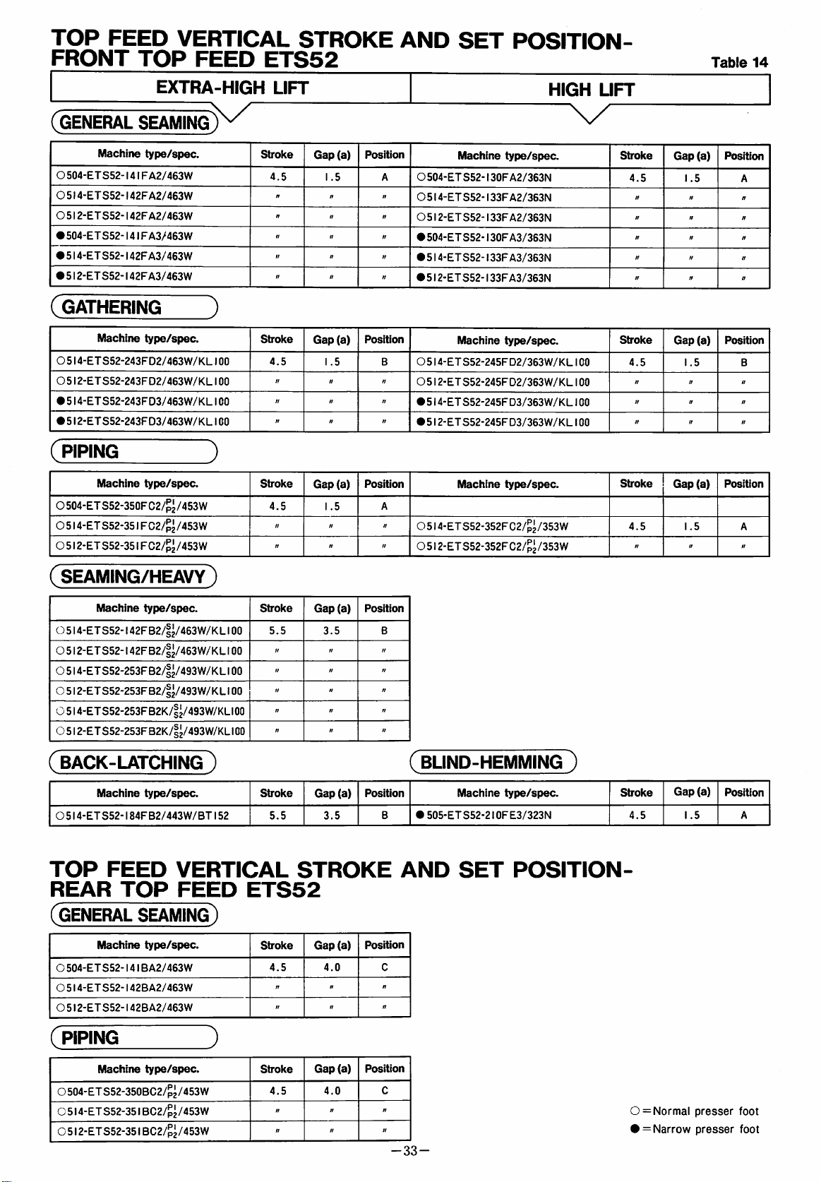
TOP
FRONT
FEED
TOP
VERTICAL
FEED
ETS52
STROKE
AND
SET
POSITION-
Table
14
EXTRA-HIGH
(GENERAL
O
504-ETS52-141FA2/463W
O
5!
4-ETS52-142FA2/463W
O
512-ETS52-142F
•
504-ETS52-141FA3/463W
►
5I4-ET852-I42FA3/463W
•
512-ETS52-142FA3/463W
SEAMING
Machine
type/spec.
A2/463W
(GATHERING
Machine
O
514-ETS52-243FD2/463W/KL100
O
512-ET852-243FD2/463W/KL100
•
514-ETS52-243FD3/463W/KL100
•
512-ET852-243FD3/463W/KL100
(
PIPING
Machine
0
504-ET
0
514-ET
O
512-ET
type/spec.
type/spec.
S52-350FC2/^^/453W
852-351
FC2/p^/453W
852-351
FC2/^^/453W
UFT
Stroke
4.5
Gap
1
.5
(a)
Position
Machine
O
504-ET
852-130F
O
514-ET
852-133F
05I2-ET852-I33FA2/363N
•
504-ET852-130F
•
5I4-ET852-I33FA3/363N
•
5I2-ET852-I33FA3/363N
type/spec.
A2/363N
A2/363N
A3/363N
HIGH
UFT
Stroke
4.5
Gap
1
.5
(a)
Position
)
Stroke
4.5
Stroke
4.5
t!
Gap
Gap
Position
(a)
1
.5
Position
(a)
1
.5
A
n
n
Machine
O
514-ET852-245FD2/363W/KL100
O
512-ET852-245FD2/363W/KL100
•
514-ETS52-245FD3/363W/KL100
•
512-ETS52-245FD3/363W/KL100
Machine
type/spec.
type/spec.
05l4-ETS52-352FC2/p2/353W
O
512-ET852-352FC2/^^/353W
Stroke
4.5
Stroke
4.5
Gap
(a)
Position
1
.5
Gap
(a)
Position
1
.5
"
"
A
»
(seaming/heavy)
Machine
O
514-ET852-142FB2/|2/463W/KLI
O
512-ETS52-142FB2/|^/463W/KL
O
514-ET852-253FB2/|^/493W/KLI
O
512-ET852-253FB2/|^/493W/KLI
0
514-ET852-253FB2K/|^/493W/KLI00
O
512-ET852-253FB2K/|^/493W/KLI
(
BACK-LATCHING
Machine
O
514-ET
TOP
REAR
(GENERAL
Machine
O
504-ET
O
514-ET
O
512-ET852-142BA2/463W
type/spec.
type/spec.
852-184F
B2/443W/
FEED
TOP
SEAMING)
type/spec.
852-141B
852-142BA2/463W
A2/463W
00
100
00
00
00
)
BT152
VERTICAL
FEED
ETS52
Stroke
5.5
Stroke
5.5
Gap
(a)
3.5
H
H
» n n
n
n
Gap
3.5
//
n
n
n
(a)
STROKE
Stroke
4.5 4.0
Gap
(a)
"
tt
"
Position
B
//
M
n
ft
Position
8
Position
C
n
n
(
BLIND-HEMMING
Machine
•
505-ETS52-2I0FE3/323N
AND
SET
type/spec.
POSITION-
)
Gap
Stroke
4.5
(a)
Position
1
.5
A
(
PIPING
Machine
O504-ET852-350BC2/^^/453W
O
514-ET852-351
O
512-ET852-351
type/spec.
BC2/p2/453W
BC2/p2/453W
J
Stroke
4.5
Gap
//
ft
Position
(a)
4.0
It
If
C
It
It
-33-
0=
Normal
• = Narrow
presser
presser
foot
foot
Page 36

TOP
FEED
FEED
The
Make
machine.
Using
shifting
Loosen
RATIO
standard
sure
Stopper
range.
Screw
STROKE
(Rg
setting
that
the
©,
AND
82)
is
as
setting
set
Lever O in
move
Stopper 0 and
DIFF.
shown
is
correct
in
Table
the
15.
for
your
correct
adjust.
©
-34-
Page 37

TOP
FEED
STROKE
AND
TOP
FEED
RATIO-FRONT
TOP
FEED
ETS52
Table
15
EXTRA-HIGH
(GENERAL
0
504-ETS52-141FA2/463W
O
514-ETS52-142FA2/463W
O
512-ETS52-142FA2/463W
•
504-ETS52-141FA3/463W
•
514-ETS52-142F
•
512-ET
(gathering
O
514-ETS52-243FD2/463W/KL100
O
512-ETS52-243FD2/463W/KL100
•
514-ETS52-243FD3/463W/KL100
•
512-ETS52-243FD3/463W/KL100
(
PIPING
SEAMING)
Machine
Machine
Machine
type/spec.
S52-142F
type/spec.
type/spec.
A3/463W
A3/463W
)
J
O504-ETS52-350FC2/^^/453W
O
514-ETS52-351
O
512-ETS52-351
FC2/^^/453W
FC2/p2/453W
UFT
Stroke
2.8-5.8
n
"
n
ft
n
Stroke
2.8-7.4
"
tt
tt
Stroke
2.8-5.8
tt tt
tt
Feed
ratio
1:o.7S
— 1:1.5
"
n
n
n
Feed
ratio
1:0.75
—
1:1
.95
tt
tt tt
"
Feed
ratio
1:0.75
— 1: i .5
ft
Setting
1-6
/;
tt
ft
tt
tt
Setting
1-9
"
It
Setting
1-6
tt
tt
HIGH
UFT
X/"
Machine
O
504-ETS52-130F
05I4-ETS52-I33FA2/363N
O
512-ETS52-133F
•
S04-ET
S52-130F
•
514-ET
S52-133F
•
512-ETS52-133F
Machine
0514-ETS52-245FD2/363W/KL100
0512-ETS52-245FD2/363W/KL100
•
514-ETS52-245FD3/363W/KL100
•
512-ETS52-245FD3/363W/KL100
Machine
05l4-ETS52-352FC2/p2/353W
05l2-ETS52-352FC2/^^/353W
type/spec.
A2/363N
A2/363N
A3/363N
A3/363N
A3/3S3N
type/spec.
type/spec.
Stroke
2.8-5.8
I
tt
00
CNJ
tt
ft
ft
tt
Stroke
It
tt
Stroke
2.8-5.8
tt
Feed
ratio
1
:o.75
~
1:1
tt
ft
tt
ft
tt
Feed
ratio
1
:o.75
— 1:1.95
tt
tt
Feed
ratio
1
:0.75
— 1:1.5
tt
.5
Setting
1-6
tt
tt
tt
tt
ft
Setting
1-9
tt
It
tt
Setting
1-6
It
(seaming/heavy)
Machine
O5l4-ETS52-l42FB2/|z/463W/KLI00
O 5 i
2-ETS52-142FB2/|^/463W/KLI
O
5I4-ETS52-253FB2/|2/493W/KLI00
O
5I2-ETS52-253FB2/I2/493W/KLI00
O
514-ETS52-253FB2K/|^/493W/KLi
O
51
2-ETS52-253FB2K/|2/493W/KLI
(
BACK-LATCHING
Machine
0
514-ET
S52-184FB2/443W/BT152
TOP
FEED
(GENERAL
Machine
0
504-ETS52-141B
0
514-ETS52-142BA2/463W
0
512-ETS52-142BA2/463W
type/spec.
)
type/spec.
STROKE
SEAMING)
type/spec.
A2/463W
Stroke
2.8-8.5
00
00
00
Stroke
2.8-8.5
AND
Stroke
2.8-5.8
//
tt
tt
ft
tt
"
tt
Feed
ratio
1:1
.2
— 1:3.6
1:0.85
— 1:2.65
tt
It
tt
Feed
ratio
1
:1.2
—
1:3.6
TOP
Feed
ratio
1
:0.75
— 1:1.5
tt
tt
Setting
l-l
l
tt
"
tt
It
tt
(
Setting
l-l
l
FEED
Setting
1-6
"
tt
BLIND-HEMMING
•
Machine
505-ET
S52-21
type/spec.
OF
E3/323N
RATIO-REAR
)
TOP
Stroke
2.8-5.8
FEED
Feed
ratio
ETS52
Setting
1-6
(
PIPING
Machine
0
504-ET
S52-350BC2/^^/453W
0
514-ETS52-351
0
512-ETS52-351
type/spec.
BC2/^^/453W
BC2/^^/453W
J
Stroke
2.8-5.8
tt
tt
i
:0.75
Feed
ratio
—
"
1:1.5
tt
Setting
1-6
tt
tt
-35-
0 = Normal
• = Narrow
presser
presser
foot
foot
Page 38

ADJUSTING
OF
TOP
FEED
The
standard
Make
sure
machine.
THE
DOG
setting
that
the
LENGTHWISE
(Rgs.83~86)
is
as
shown
setting
is
correct
POSITION
in
Table
for
16,
your
To
adjust
1.
Pressing
and
set
the
2.
Shift
Top
back
extremely
the
top
feed
3.
Turn
the
Dog 0 to
4.
Adjust
correct
Feed
plate.
gap
dimension.
Dog © and
Loosen
and
adjust.
ADJUSTING
OF
TOP
FEED
The
standard
Make
sure
machine.
Push
Button
stitch
Feed
in
stroke
handwheel
the
front
(a)
Screw
O,
THE
DOG
setting
that
the
O,
turn
the
length
Adjusting
between
SIDEWISE
to
the
maximum.
Lever O to
the ( + ) direction,
to
the
maximum.
and
bring
dead
point.
(A)
and
(B)
(B)
is
the
front
(A)
is
that
of
the
move
Top
POSITION
Feed
(Fig.87)
is
as
shown
setting
is
in
correct
handwheel
the
and
set
Top
Feed
to
the
tip
of
Top
needle
Bar
0
Table
for
16.
your
<>1
Fig.84
Flg.85
—(a)
To
adjust:
1.
Turn
the
feed
dog
2.
Loosen
3.
Move
Top
the
gap
feed
dog
to
the
correct
4.
When
fixed,
clamp
and
0,
i—
Note:
—
The
marks
show
the
direction
the
bottom
handwheel
to
the
Screws
Feed
between
and
the
the
position
the
and
tighten
(+)
right
(—)
based
feed
and
bring
bottom
0,
dead
point.
0
Dog 0 sidewise
the
left
end
of
left
end
of
the
height.
of
the
top
top
feed
bar
with
Screws
and
(—)
direction
on
dog.
0,
listed
(+)
the
left
©.
in
and
1-©
the
and
the
top
feed
Guides
Table
end
bottom
adjust
bottom
feed
dog
the
face
dog
is
0
16
left
of
r
36-
Page 39

HORIZONTAL
TOP
FEED
POSITION-FRONT
TOP
FEED
ETS52
Table
16
EXTRA-HIGH
(GENERAL
O
504-ETS52-141F
O
514-ETS52-142F
O
512-ETS52-142F
•
504-ET
•
514-ET
•
512-ET
SEAMING
{Machine
S52-141F
S52-142F
S52-142F
type/spec.
A2/463W
A2/463W
A2/463W
A3/463W
A3/463W
A3/463W
(GATHERING
Machine
O
514-ET
O5I2-ETS52-243FD2/463W/KLI00
•
514-ETS52-243FD3/463W/KL100
•
512-ETS52-243FD3/463W/KL100
(
PIPING
Machine
O
504-ET
O
514-ETS52-351
O
5!
2-ETS52-351
type/spec.
S52-243F
D2/463W/
type/spec.
S52-350FC2/p2/453W
FC2/^^/453W
FC2/p2/453W
)
KL100
J
UFT
Back
and
position
14.0
n
tf
16.5
ft
ft
Back
and
position
13.0
ft
15.5
"
Back
and
position
14.0
"
ft
forth
forth
forth
Right
to
position
+
1.1
ff
+
3.6
//
It
Right
to
position
+ 1.
tt
+3.6
tt
Right
to
position
+ 1.1
"
tt
left
•
•
•
left
1
•
•
left
Machine
O
504-ETS52-130F
O
514-ETS52-133F
O
512-ETS52-133F
504-ETS52-13GF
514-ET
512-ET
(Machine
O
514-ETS52-245FD2/363W/KL100
O
512-ETS52-245FD2/363W/KL100
514-ETS52-245FD3/363W/KL100
512-ETS52-245FD3/363W/KL100
Machine
O
514-ETS52-352FC2/p2/353W
S52-133F
S52-133F
type/spec.
A2/363N
A2/363N
A2/363N
A3/363N
A3/363N
A3/363N
type/spec.
type/spec.
05l2-ETS52-352FC2/p^/353W
HIGH
UFT
Back
position
Back
position
Back
position
and
14.0
tt
ff
16.5
ft
tt
and
13.0
"
15.5
"
and
14.0
"
forth
forth
forth
Right
to
position
+ 1.1
ft
n
, +3.6
ft
ft
Right
to
position
+ 1.
+
3.6
rr
Right
to
position
+ 1.1
tt
left
left
1
left
(seaming/heavy)
Back
(Machine
type/spec.
5I4-ETS52-I42FB2/|^/463W/KLI00
O
512-ETS52-142FB2/|^/463W/KL
u
514-ETS52-253FB2/|^/493W/KL
O
512-ET
S52-253F
B2/|^/493W/
K
L100
100
100
O5l4-ETS52-253FB2K/|2/493W/KLI0a
O
512-ETS52-253FB2K/|2/493W/KL
(back-latching
Machine
O
514-ETS52-184FB2/443W/BT152
type/spec.
HORIZONTAL
(GENERAL
O
504-ETS52-141BA2/463W
O
514-ETS52-142BA2/463W
0
512-ETS52-142BA2/463W
SEAMING)
Machine
type/spec.
100
)
TOP
and
position
12.0
tt
tt
ft
tt
tt
Back
and
position
12.0
FEED
Back
and
position
43.5
tt
"
forth
Right
to
left
position
+ 1.1
"
+2.2
ft
tt
tt
(
BLIND-HEMMING
Right
to
position
+ 1.
left
1
•
505-ETS52-2I0FE3/323N
forth
POSITION-REAR
Right
to
position
-0.7
"
tt
left
forth
Machine
type/spec.
TOP
)
FEED
Back
and
position
17.5
forth
ETS52
Right
to
position
+ 1.45
left
(PIPING
(Machine
O504-ETS52-350BC2/p2/453W
O
514-ETS52-351
O
512-ETS52-351
type/spec.
BC2/p2/453W
BC2/p2/453W
)
Back
and
position
43.5
tt
tt
forth
Right
to
position
-0.7
//
tt
left
-37-
0 = Normal
• = Narrow
presser
presser
foot
foot
Page 40

ADJUSTING
The
standard
Make
machine.
—
Note:
Be
sure
upper
dog.
sure
to
or
Table
TOP
setting
that
the
check
lower
17.
FEED
is
setting
your
dead
DOG
HBGHT
as
shown
is
machine
point
of
(ng8.88-9i)
in
Table
correct
at
either
the
to
top
17.
your
the
feed
Adjustments
•
Lower
is
1.
Loosen
gap
2.
Make
the
3.
Lower
and
feed
For
dead
in
the
lowest
Nut
(a)
to
sure
correct
Top
adjust
dog
adjusting,
Shaft 0 up
Adjustments
•
Upper
is
1.
Loosen
gap
2.
Make
the
3.
Raise
position
upper
top
For
dead
in
the
highest
Nut
(a)
to
sure
correct
Top
and
surface
feed
dog
adjusting,
Shaft © up
at
the
lower
point
is
position.
O,
turn
25mm.
that
Top
position.
Feed
Dog 0 to
the
gap
and
the
loosen
and
down.
at
the
upper
point
is
position.
O,
turn
25mm.
that
Top
position.
Feed
Dog 0 to
adjust
of
the
to
the
loosen
and
down.
dead
point:
when
the
Screw o and
Feed
Dog 0 is
Table
(b)
top
14.
the
lowest
between
feed
dog
Screw O and
dead
point:
when
the
Screw 0 and
Feed
Dog 0 is
Table
the
correct
14.
gap
(c)
needle
dimension.
plate
Screw O and
top
feed
adjust
set
position
the
bottom
to
0.2mm.
top
feed
adjust
set
the
highest
between
and
dog
to
move
dog
to
the
the
move
lower
Upper
dead
point:
(b)0.2mm
dead
point
Fig.SO
(b)0.2mm
Fig.91
(c)3.5'™'i
-38-
(0)7.0"""
Page 41

VERTICAL
TOP
FEED
POSiTION-FRONT
TOP
FEED
ETS52
Table
17
EXTRA-HIGH
(GENERAL
O
504-ETS52-141F
O
514-ET
0512-ETS52-142F
•
504-ETS52-141F
•
514-ETS52-142F
•
512-ETS52-142F
(GATHERING
O
514-ETS52-243FD2/463W/KL100
O5I2-ETS52-243FD2/463W/KLI00
•
514-ETS52-243F
•
5I2-ETS52-243FD3/463W/KLI00
(
PIPING
SEAMING
Machine
S52-142F
Machine
Machine
type/spec.
A2/463W
A2/463W
A2/463W
A3/463W
A3/463W
A3/463W
type/spec.
D3/463W/
type/spec.
)
KL100
3
O504-ETS52-350FC2/^^/453W
0514-ETS52-351
O
512-ET
FC2/p2/453W
S52-351
FC2/^^/453W
LIFT
Height
0.2
H
it
»
n
ti
Height
3.5
n
ti
ti
Height
0.2
Checking
dead
point
Bottom
"
«
n
Checking
dead
point
Top
tt
tt
Checking
dead
point
Bottom
n
H
Machine
O
504-ETS52-130F
05I4-ETS52-I33FA2/363N
0512-ETS52-133F
•
504-ETS52-130F
•
514-ETS52-133F
•512-ETS52- i 33F
Machine
0
514-ETS52-245FD2/363W/KL100
O
512-ETS52-245FD2/363W/KL100
•
514-ETS52-245FD3/363W/KL100
•
512-ETS52-245FD3/363W/KL100
Machine
type/spec.
A2/363N
A2/363N
A3/363N
A3/363N
A3/363N
type/spec.
type/spec.
HIGH
LIFT
05l4-ETS52-352FC2/^^/353W
05l2-ETS52-352FC2/^^/353W
Height
0.2
it
It
H
n
n
Height
3.5
n
It
tt
Height
0.2
tt tt
Checking
dead
point
Bottom
it
it
it
it
It
Checking
dead
point
Top
It
tt
It
Checking
dead
point
Bottom
(seaming/heavy)
Machine
O
514-ETS52-142FB2/|2/463W/KL
O
512-ETS52-142FB2/|2/463W/KL
O
514-ET
0
5I2-ETS52-253FB2/|2/493W/KLIOO
0 5 i
4-ET
O
512-ETS52-253FB2K/|^/493W/KLI
C
BACK-LATCHING
Machine
O
514-ET
VERTICAL
(GENERAL
Machine
O
504-ET
O
514-ET
O
512-ETS52-142BA2/463W
type/spec.
S52-253F
S52-253F
B2/|^/493W/KL
B2K/|2/493W/KL
type/spec.
S52-184F
B2/443W/
SEAMING)
type/spec.
S52-141B
S52-142B
A2/463W
A2/463W
)
BT152
TOP
100
100
100
100
00
FEED
Height
5.5
II
It
"
II
11
Checking
dead
point
Top
tt
tt
tt
tt
n
(
Height
5.5
POSITION-REAR
Height
0.2
"
tt
Checking
dead
point
Top
Checking
dead
point
Bottom
It
It
BLIND-HEMMING
Machine
•
505-ETS52-2I0FE3/323N
type/spec.
TOP
)
FEED
Height
0.2
ETS52
Checking
dead
point
Bottom
(PIPING
Machine
O504-ETS52-350BC2/^^/453W
O
514-ETS52-351
O
512-ETS52-351
type/spec.
BC2/p2/453W
BC2/^^/453W
)
Height
0.2
tt
"
Checking
dead
point
Bottom
tl
ft
-39-
0 = Normal
• = Narrow
presser
presser
foot
foot
Page 42

ADJUSTING
FEED
The
Make
machine.
For
1.
2.
3.
4.
5.
6.
7.
8.
9.
DOG
standard
sure
setting:
Turn
to
Turn
the
Lower
Lever
Keeping
Screws
end
0mm
Loosen
set
and
the
0mm
correct
0.
foot
sure
correct
Adjusting
37mm.
the
highest
Lever
O,
of
Presser
and
Nut
gap
(d)
Lower
Keeping
Lever © and
Pin 0 to
gap
and
Lower
For
When
Lever
dimension.
adjusting,
Lever 0 is
is
that
height.
PRESSES
LIFT
(Rgs.92-95)
setting
that
the
handwheel
position.
and
Pin e to
the
condition
0,
adjust
Arm
tighten
©,
turn
to
25mm.
the
the
condition
between
tighten
0,
loosen
lifted
to
Upper
FOOT
is
as
setting
AND
shown
is
correct
Screw O and
and
lift
the
and
adjust
the
of
the
the
gap
correct
above
gap
Shaft 0 and
Screw
O.
Adjusting
adjust
gap
correct
dimension.
of
the
Screw 0 and
(b)
above
Lever 0 and
Screw
and
0.
adjust
gap
Nut 0 and
lowered
the
Feed
and
correct
Dog 0 is
TOP
in
Table
to
your
set
gap
needle
(a)
between
dimension.
3.,
loosen
between
Plate 0 to
between
6.,
adjust
Plate 0 to
(e)
to
turn
Screw
the
presser
height,
lifted
make
to
18.
(c)
to
the
0
the
the
(c)37niffl
(cDzSmm
o
—
Note:
If
necessary,
between
correct
feed
10.
Lift
and
the
For
dimension
height.
the
adjust
upper
adjusting,
Stopper 0 up
widen
or
Lever 0 and
to
obtain
presser
so
face
foot
to
that
Stopper 0 lightly
of
Presser
loosen
and
Screw 0 and
down.
shorten
the
Pin 0 than
the
correct
the
correct
Foot
0.
gap
b
the
top
height
brushes
move
•40-
Page 43

PRESSER
FOOT
AND
EXTRA-HIGH
TOP
LIFT
FEED
HEIGHTS-FRONT
TOP
HIGH
FEED
LIFT
ETS52
Table
18
(GENERAL
O
504-ET
O
514-ET
O
5!
2-ETS52-142F
•
504-ETS52-141F
•
514-ETS52-142F
•
512-ET
(GATHERING
O
514-ETS52-243FD2/463W/KL100
O
512-ETS52-243FD2/463W/KL1
•
514-ETS52-243FD3/463W/KL100
•
512-ETS52-243FD3/463W/KL100
(PIPING
SEAMINot^
Machine
S52-141FA2/463W
S52-142F
S52-142F
Machine
Machine
type/spec.
A2/463W
A2/463W
A3/463W
A3/463W
A3/463W
)
type/spec.
J
type/spec.
CO
O504-ETS52-350FC2/^^/453W
0514-ETS52-351
0512-ETS52-351
FC2/^^/453W
FC2/^^/453W
Foot
lift(e)
5.5
7.0
ft
5.5
7.0
tt
Foot
Iift(e)
7.0
tt
tt
Foot
iiftfe)
6.0 6.0
tt
It
Feed
lift
5.5
7.0
5.5
7.0
Feed
lift
7.0
Feed
lift
n
ft
tt
tt
tt
It
tt
Gap
Gap
(b)
(a)
2.0 2.0
n n
n
tt
n
n
Gap
Gap
(b)
(a)
2.0
»
tt tt
tt
Gap
Gap
(b)
(a)
2.0
2.0
It
"
Machine
O
504-ET
O
514-ET
O
512-ETS52-133F
"
n
•
504-ETS52-130F
n
•
514-ETS52-133F
It
•
512-ETS52-133F
Machine
O
514-ETS52-245FD2/363W/KL100
1
.0
It
O
512-ETS52-245FD2/363W/KL100
•
514-ETS52-245FD3/363W/KL100
tt
•
512-ETS52-245FD3/363W/KL100
tt
O
514-ETS52-352FC2/^i
tt
05l2-ETS52-352FC2/^^/353W
type/spec.
S52-130F
S52-133F
type/spec.
Machine
A2/363N
A2/363N
A2/363N
A3/363N
A3/363N
A3/363N
type/spec.
/353W
Foot
Feed
llft(e)
m
5.5 5.5
tt
tt
tt tt
tt
n
tt tt tt
tt
tt
Foot
Feed
lift(e)
lift
5.5
5.5
tt
tt tt
tt tt
tt
tt
Foot
Food
Iift(e)
lift
5.5
5.5
tt
tt
Gap
(a)
2.0
Gap
(a)
2.0
Gap
(a)
2.0
Gap
(b)
2.0
tt
tt
tt
tt
tt
tt
tt
tt
tt
Gap
(b)
1.0
tt
tt
tt
tt
tt
Gap
(b)
2.0
If
tt
(SEAMING/HEAVY
Machine
O
514-ETS52-142FB2/|^/463W/KL
O
512-ETS52-142FB2/|^/463W/K
O
5I4-ETS52-253FB2/|^/493W/KLI00
O
512-ET
S52-253F
O
514-ETS52-253FB2K/|^/493W/KLI
O 5 i
2-ET
S52-253F
type/spec.
B2/|^/493W/
B2K/|^/493W/KLI
(back-latching
Machine
O
514-ETS52-184FB2/443W/BT152
PRESSER
(GENERAL
Machine
O504-ETS52-14 i BA2/463W
05I4-ETS52-I42BA2/463W
O
512-ET
S52-142B
type/spec.
FOOT
SEAMING)
type/spec.
A2/463W
)
L100
K
L100
)
AND
100
00
00
Foot
lift(e)
7.0
tt
tt
tt
tt
tt
Foot
lift(e)
7.0
TOP
Foot
lift(e)
6.0 6.0
tt tt
tt
Feed
lift
7.0
tt
tt
tt
tt
tt
Feed
lift
7.0
FEED
Feed
lift
tt
Gap
Gap
(b)
(a)
1
2.0
.0
//
tt
tt
tt
tt
tt
11
tt
tt
II
(BUND-HEMMING
Gap
Gap
(b)
(a)
1
.0
•
2.0
505-ETS52-2I0FE3/323N
HEIGHTS-REAR
Gap
Gap
(b)
(a)
1
2.0
.2
//
tt
tt
tt
Machine
type/spec.
TOP
)
Foot
Iift(e)
5.5 5.5
FEED
Feed
Gap
lift
(a)
2.0
ETS52
Gap
(b)
2.0
(piping
Foot
Machine
type/spec.
O504-ETS52-350BC2/^^/453W
0
514-ET
S52-35 i BC2/p2
O
512-ETS52-35
/453W
i
BC2/^^/453W
lift(e)
5.0
tt
tt
Feed
lift
6.0
tt
tt
Gap
(a)
2.0
Gap
(b)
0.5
tt
tt
tt
tt
-41-
0 = Normal
• = Narrow
presser
presser
foot
foot
Page 44

ADJUSTING
PRESSER
SIDEWISE
ARM
(Rg
96)
POSITION
OF
Presser
Presser
when
down,
foot
For
shift
—
Note:
When
arm
Bar 0 is
Hand
so
parallel
adjusting,
Presser
tightening
Lever 0 to
PRESSER
1.
Loosen
on
the
presser
2.
Turn
the
top
position.
3.
Align
the
that
of
presser
plate.
For
i—
Note:
For
foot
adjusting,
setting
©, 0 and
should
Lift
as
to
make
with
loosen
Arm
the
FOOT
Screw © until
foot
handwheel
needle
the
needle
sit
loosen
the
type
be
in
smooth
on
Lever O is
the
slot
the
top
feed
Screws O and © and
Shaft
0.
Screw
original
0,
position.
SETTING
the
is
eliminated.
to
lift
slot
of
the
plate.
even
and
Screw
of
Fig.
adjust.
position
Presser
Arm
moved
of
the
dog.
be
sure
to
(Figs.96~98)
spring
the
presser
Also,
flat
needle
foot
make
on
the
pressure
©.
98,
loosen
Screws
where
0
up
and
presser
return
to
the
with
the
needle
Rg.97
Fig.98
ADJUSTING
1.
Adjust
the
needle
For
adjusting,
Bracket © up
2.
Adjust
the
lower
1.0mm.
For
adjusting,
Edge
Guide
EDGE
Edge
Guide © so
plate.
gap
(a)
knife
©.
GUIDE
loosen
and
down.
between
and
Edge
loosen
(Fig.99)
that
it
lightly
Screw © and
the
cutting
Guide © to
Screw © and
brushes
edge
move
of
0.5
—
slide
-42-
(a)0.5— I .Omm
Page 45

ADJUSTING
1.
Set
Edge
the
needle
For
adjusting,
slide
bracket
2.
Adjust
the
1.0mm.
For
Edge
3.
Set
accurately
presser
gap
lower
adjusting,
Guide
Piping
foot
PIPING
BINDER
Guide ® so
plate.
loosen
(b)
knife
Screw ® and
between
and
Edge
loosen
Binder ® so
inserted
sole
into
from
(Fig.ioo)
that
it
lightly
the
cutting
Guide ® to
Screw
that
the
Piping
Binder
brushes
vertically
edge
and
Cord ® is
groove
®.
0.5
slide
in
of
—
the
(b)0.5~ I .Omm
ADJUSTING
Adjust
manner.
1.
Open
2.
Set
plate.
For
slide
3.
Fig.
hole.
the
Blade ® is
For
Blade
4.
Turn
is
on
Turn
to
adjust
5.
When
raised
pedal,
and
For
Stopper
•
When
the
•
When
Blade ® becomes
SHIRRING
Shirring
Presser
Blade ® so
adjusting,
Blade
102.
overlook
®.
Set
Then,
3.0mm.
adjusting,
®.
Worm ® left
Blade
@.
right 3 — 4 times
the
the
presser
up
to
set
the
Blade ® to
adjusting,
Cable
lift
of
it
is
BUDE
(Rgs.ioi~i03)
Blade ® in
Arm
to
the
left.
as
to
lightly
loosen
the
adjust
needle
Screw ® and
tip
of
so
that
loosen
until
spring
the
pressure
foot
specified
gap
between
3.0mm.
loosen
Nut ® and
Stopper ® is
brush
Blade ® to
the
gap
and
the
Screw ® and
no
spring
from
on
and
top
height
the
let
Blade ® becomes
let
out
to
(+)
side,
small.
the
following
the
vertically
the
(c)
between
right
pressure
that
position
Blade
feed
dog
by
foot
needle
move
in
to
(—)
large.
the
needle
needle
end
of
slide
®.
are
lift
plate
Cable
side,
lift
of
\[
(c)
3.
Omm
-43-
(d) 3 .Qmm
 Loading...