

Page 1
INSTRUCTIONS
Cat.
No.
9A2045
December,
1984
TOP
AND
BOTTOM,
SAFETY
ecember. 1 98
DIFFERENTIAL
STITCH
MACHINES
FEED
Page 2
INTRODUCTION
This
booklet
operation
machines.
before
derive
DAILY
Before
1.
Check
damaged.
2.
Check
3.
Check
4.
Check
formed.
5.
Check
lines
6.
Check
lubrication
7.
Check
while
After
1.
Clean
needle
2.
If
it
rapair.
3.
Place a dust
and
use
of
the
best
MAINTENANCE
starting
needle
needle
threading
thread
oil
of
oil
oil
oil
running
close
of
the
machine.
plate
any
trouble
to
the
plant
contains
maintenance
Careful
indicator
gauge.
is
parts.
monitor
work:
reading
the
machine
use
from
work:
is
in
sound
is
correctly
is
correct.
chain
of
not
color
the
machine.
tip
short
Especially,
and
looper.
or
irregularity
mechanic
cover
over
some
of
will
it.
condition
set.
about
is
between
for
is
changed
for
the
notes
the
of
10mm
ETS
this
help
length
on
booklet
you
and
the
the
manual
to
clean
around
is
found,
adjustment
machine.
the
series
to
not
is
two
green
report
or
FOR
SAFETY
1.
Make
sure
2.
Be
well
with
energizing.
3.
Turn
the
4.
Be
an
5.
Make
the
off
work
sure
to
electric
sure
checking
6.
Make
when
sure
the
replacing
NOTES
1.
Run
the
2.
In
after
drops
guide,
3.
Keep
level
lines
4.
Change
one
5.
If
even
ON
new
maximum
using
stop-page
of
needle
the
indicator
of
oil
oil
month
the
oil
when
immediately
6.
Thread
the
your
illustration.
Belt
Guard
careful
in
power
Motor
table.
and
Switch
turn
off
breakdown.
to
turn
cleaning
Motor
machine
Needles,
USE
machine
for
the
machine
for
oil
manually
holder
machine
is
gauge.
entirely
in
operation.
monitor
the
machine
and
check
machine
is
properly
connecting
source
whenever
Power
off
has
Switch
Power
the
machine.
completely
requires
etc.
at a 20%
the
first
one
for
the
some
time,
to
the
and
upper
oil
level
always
color
at
between
the
does
is
run,
the
filter.
correctly
fitted.
the
machine
and
checking
you
in
case
Switch
stopped
threading,
less
speed
month.
first
time
lubricate
needle
looper
so
that
the
end
of
the
not
turn
stop
operation
according
leave
of
before
than
and
2~3
holder
holder.
the
oil
two
first
green
to
Re:
Thread
Thread
skipping
chain
chain
of
stitch
is
always a thread
Be
sure
to
obtain
after
threading
and
necessary
at
the
start
chain
of
thread
chain
change
for
of
sewing.
about
before
of
needle.
preventing
Keep
10cm
length.
sewing,
Page 3
CONTENTS
Pattern
Assembling
Machine
Driving
Installation
Turning
Lubrication
Checking
Silicone
Needles
Replacing
Threading
Regulating
Presser
Presser
Stitch
Diffential
Top
Adjusting
Regulating
Needle
Looper
Chainstitch
Changing
Changing
Knives
Bottom
Auxiliary
Bottom
Needle
Lower
Upper
Chainstitch
Overlook
Chainstitch
Adjusting
Adjusting
Setting
Adjusting
Top
Adjusting
Adjusting
Adjusting
Adjusting
Height
Adjusting
Presser
Adjusting
Adjusting
Adjusting
paper
speed
motor
of
direction
and
oil
for
needles
thread
arm
foot
length
feed
feed
stroke
top
seam
thread
thread
looper
upper
lower
feed
feed
feed
height
looper
looper
looper
needle
needle
the
vertical
position
the
feed
stroke
the
the
top
presser
of
upper
sidewise
foot
edge
piping
shirring
for
the
machine
pulley
machine
replacing
H.R.
swinging-in
pressure
adjustment
adjustment
feed
guide
takeup
height
dog
leveling
setting
setting
setting
lengthwise
lengthwise
lengthwise
sidewise
feed
setting
guide
semi-submerged
rest
board
and
belting
of
machine
oil
filter
device
tension
and
-out
adjustment
pressure
width
setting
thread
position
and
looper
handling
knife
knife
height
position
adjustment
setting
guard
setting
guard
setting
position
stroke
of
and
top
diff.
of
top
feed
dog
position
feed
feed
ratio
position
position
dog
foot
and
knife
holder
position
height
of
top
feed
of
presser
binder
blade
installation
thread
of
guide
bottom
setting
feed
dog
of
top
feed
dog
of
top
feed
dog
top
feed
dog
dog
lift
arm
positions
dogs
^
2
3
4
4
4
4
6
7
7
8
8
8
8
13
13
14
14
15
15
15
16
16
18
18
19
19
20
20
20
22
22
24
26
27
28
29
30
30
30
32
34
34
36
38
40
42
42
42
43
43
-
1
Page 4
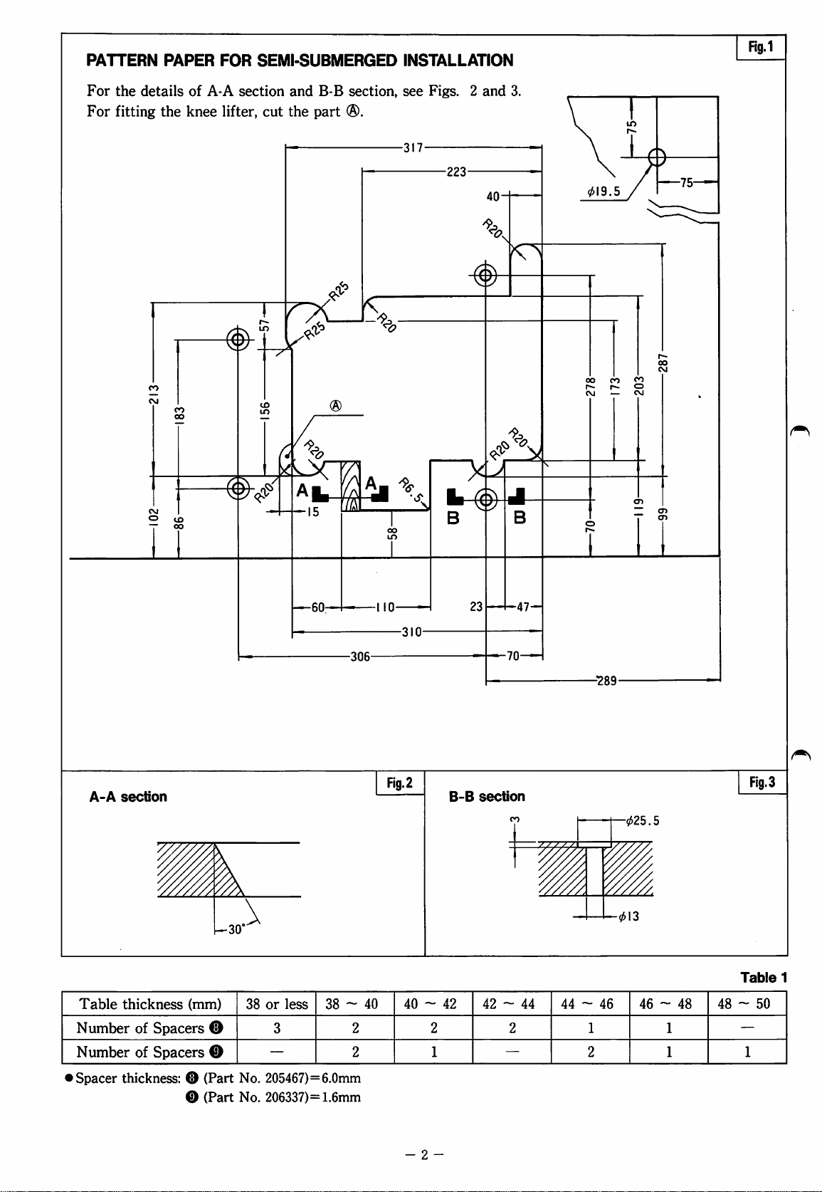
PATTERN
For
the
For
fitting
PAPER
details
the
CO
CM
of
knee
FOR
A-A
section
lifter,
SEMI-SUBMERGED
and
B-B
section,
cut
the
part
®.
rx
CO
3^
00
"7^
I
INSTALLATION
see
-317-
<7
o
Figs. 2 and
-223-
40-
3.
CO
r-
CM
CO CO
i>-
—
Rg.1
o
CM
A-A
section
CM
O I
B
B-B
23
section
J
B
-47-
-70-
-"289-
Fig.3
-025.5
kLX
a
rt
15
—60-
-306-
-■I
■I
'Si
10-
-310-
Flg.2
\
—30
Table
Number
Number
Spacer
thickness: O (Part
thickness
of
Spacers
of
Spacers
(mm)
0
0
0
(Part
38
or
less
3
—
No.
205467)=6.0mm
No.
206337)=1.6mm
40 ~ 42
2
2
2
1
- 2 -
42 - 44 44 ~ 46
2
—
-013
Table
1
46 ~ 48
1
2
1
1
48 ~ 50
—
1
Page 5
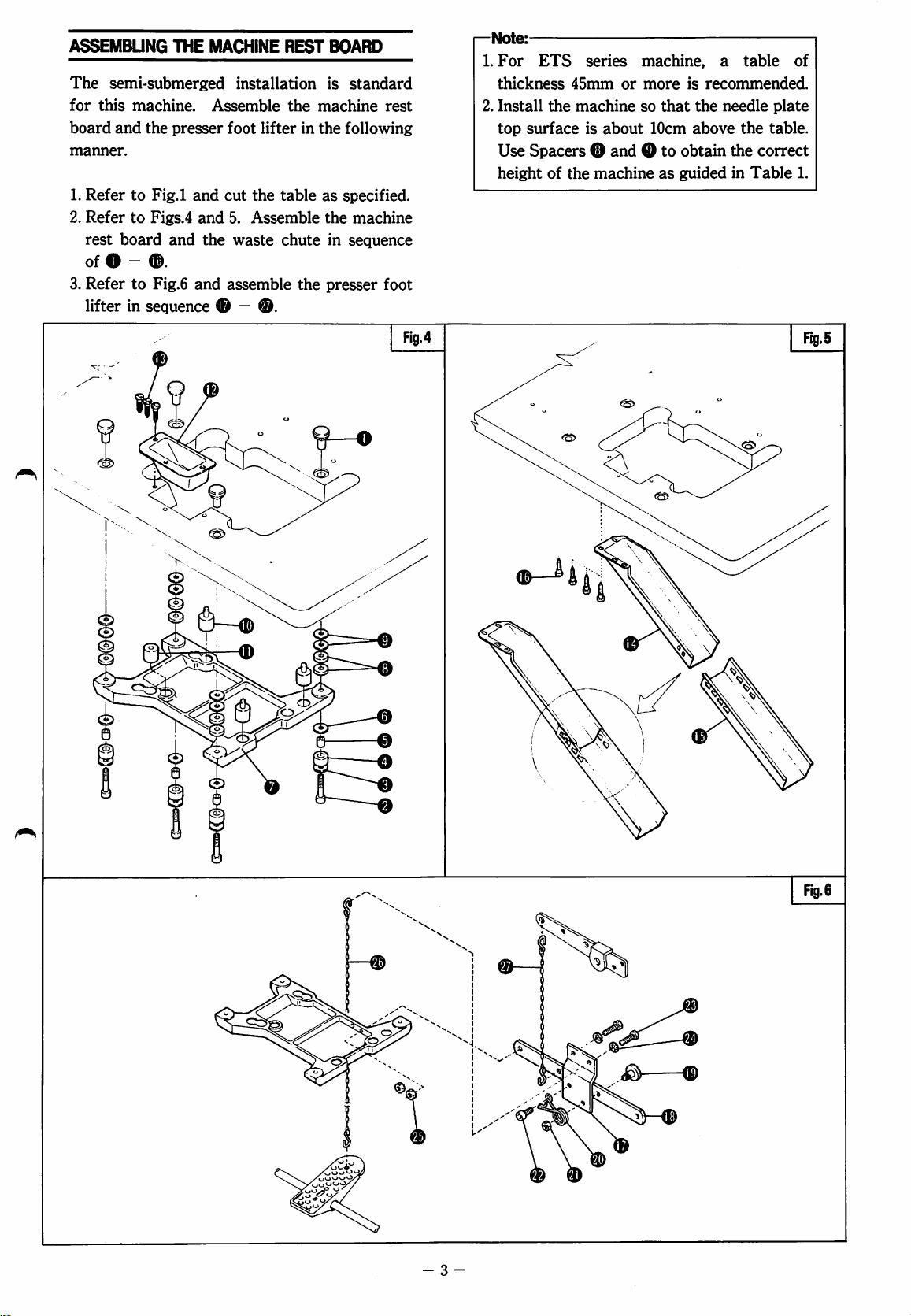
ASSEMBUNG
The
semi-submerged
for
this
machine.
board
and
the
manner.
1.
Refer
to
Fig.l
2.
Refer
to
Figs.4
rest
board
of O -
3.
Refer
lifter
®.
to
Fig.6
in
sequence
THE
MACHINE
Assemble
presser
and
foot
cut
and
and
the
and
(D
REST
installation
the
machine
lifter
in
the
the
table
as
5.
Assemble
waste
assemble
the
chute
the
presser
—
BOARD
is
standard
rest
following
specified.
machine
in
sequence
foot
Fig.4
—Note:
1.
For
thickness
2.
Install
top
Use
height
ETS
surface
45mm
the
machine
series
or
is
about
machine, a table
more
so
that
10cm
Spacers ® and O to
of
the
machine
as
is
recommended.
the
needle
above
obtain
guided
the
in
plate
the
table.
correct
Table
of
1.
0
- 3 -
Page 6
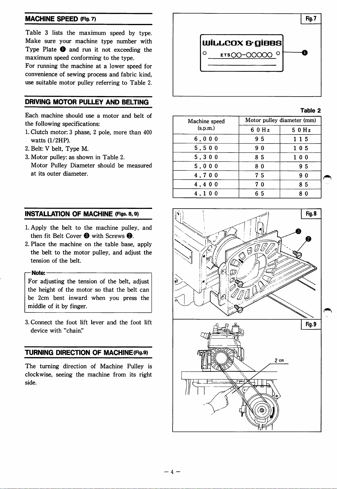
MACHINE
SPEED
(Fig.
7)
Fia.7
Table 3 lists
Make
Type
sure
Plate O and
maximum
For
running
convenience
use
suitable
DRIVING
Each
machine
the
following
1.
Clutch
watts
(1/2HP).
2.
Belt: V belt.
3.
Motor
Motor
at
its
outer
the
your
speed
the
of
sewing
motor
MOTOR
should
specifications:
motor: 3 phase, 2 pole,
Type
pulley:
Pulley
diameter.
maximum
machine
run
it
conforming
machine
at a lower
process
pulley
referring
PULLEY
use a motor
M.
as
shown
Diameter
in
should
speed
type
number
not
exceeding
to
the
type.
and
fabric
AND
more
Table
2.
be
by
type.
with
the
speed
for
kind,
to
Table
2.
BELTIN^
and
belt
of
than
400
measured
UJiL.L.CaX
o
Machine
speed
(s.p.m.)
6,000
5,500
5,300
5,000
4,700
4,4 0 0
4,100
B'giBBS
ETSOO-OOOOO
Motor
pulley
6 0 Hz
9
5
9
0
8
5
8
0
7
5
7
0
6
5
o
diameter
5 0 Hz
1 1 5
10
1
Table
(mm)
5
0 0
9
5
9
0
8
5
8
0
2
INSTALLATION
1.
Apply
then
2.
Place
the
tension
Note:
For
the
be
middle
3.
Connect
device
TURNING
The
clockwise,
side.
the
fit
Belt
the
machine
belt
to
of
the
adjusting
height
2cm
of
bent
of
it
by
the
with
DIRECTION
turning
seeing
OF
MACHINE
belt
to
the
machine
Cover 0 with
on
the
the
motor
belt.
the
the
inward
pulley,
tension
motor
so
when
finger.
foot
lift
lever
"chain."
OF
direction
the
of
machine
(Figs.
8,9)
pulley,
Screws
table
of
the
that
and
MACHINE(Fig.9)
Machine
and
belt,
the
you
the
from
0.
base,
adjust
adjust
belt
press
foot
Pulley
its
and
apply
the
can
the
lift
is
right
n
Fig.9
- 4 -
Page 7
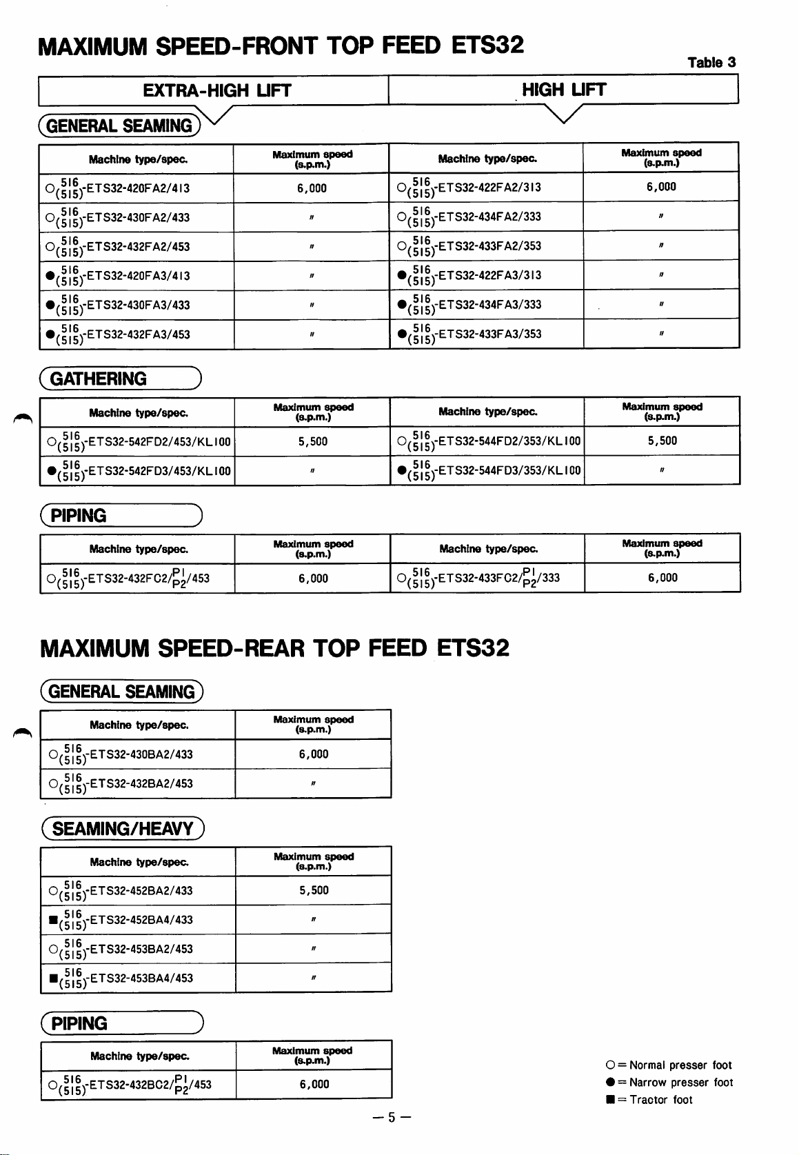
MAXIMUM
SPEED-FRONT
TOP
FEED
ETS32
Table
3
EXTRA-HIGH
(GENERAL
0( 1 ]
^)-ETS32-420FA2/413
0(
51
5)-ETS32-430F
SEAMING)
Machine
type/spec.
K/"
A2/433
IIJ-ETS32-432FA2/453
•(1IIJ-ETS32-420FA3/413
•(1
||)-ETS32-430FA3/433
•(II1J-ETS32-432F
(GATHERING
Machine
0(|
11J-ETS32-542FD2/453/KL100
•(II1J-ETS32-542FD3/453/KL
A3/453
)
type/spec.
i
00
UFT
Maximum
Maximum
speed
(s.p.m.)
6,000
//
//
//
//
n
speed
(s.p.m.)
5,500
ft
HIGH
Machine
type/spec.
0(|||)-ETS32-422FA2/3i3
0(| 1 |)-ETS32-434FA2/333
0(
11
|)-ETS32-433FA2/353
•(|1|)-ETS32-422FA3/3I3
•(11
|)-ETS32-434F
A3/333
•(II1J-ETS32-433FA3/353
Machine
0(11
|)-ETS32-544FD2/353/KL
•(II
|)-ETS32-544FD3/353/KL
type/spec.
UFT
i
00
100
Maximum
(s.p.m.)
6,000
Maximum
(s.p.m.)
5,500
speed
ff
n
ft
ft
ft
speed
ft
(
PIPING
Machine
type/spec.
0(|||j-ETS32-432FC2/^^/453
MAXIMUM
(GENERAL
SEAMING)
Machine
type/spec.
0(| 1 |)-ETS32-430BA2/433
0(| 1 |)-ETS32-432BA2/453
3
SPEED-REAR
Maximum
(s.p.m.)
6,000
Maximum
(s.p.m.)
6,000
speed
TOP
speed
11
(seaming/heavy)
Machine
type/spec.
Maximum
0(|||j-ETS32-452BA2/433
■(II
|)-ETS32-452BA4/433
speed
(8.p.m.)
5,500
n
Machine
type/spec.
0(|||j-ETS32-433FC2/^^/333
FEED
ETS32
Maximum
(s.p.m.)
6,000
speed
Maximum
(s.p.m.)
6,000
tf
ft
speed
-5-
0(
11
|yETS32-453BA2/453
■(|||)-ETS32-453BA4/453
(
PIPING
Machine
type/spec.
0(|||j-ETS32-432BC2/p2/453
O = Normal
• = Narrow
■ = Tractor
presser
presser
foot
foot
foot
Page 8
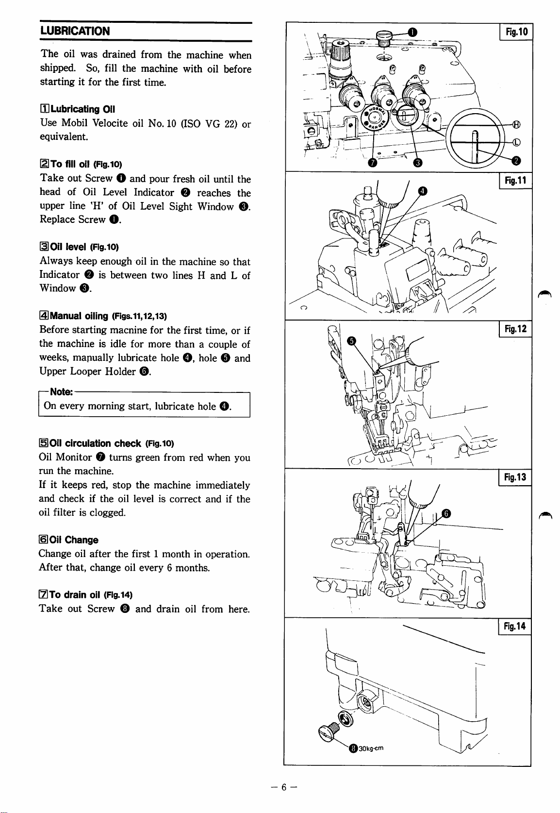
LUBRICATION
The
oil
was
drained
shipped.
starting
[H
Lubricating
Use
equivalent.
UTo
Take
head
upper
Replace
noil
Always
Indicator ® is
Window
So,
it
for
Mobil
Velocite
fill
oil
(Fig.
out
Screw O and
of
Oil
line
'H'
Screw
level
(Fig.iO)
keep
enough
®.
fill
the
Oil
Level
from
the
the
machine
first
time.
oil
No.
10
with
(ISO
10)
pour
fresh
Indicator O reaches
of
Oil
Level
O.
oil
between
Sight
in
the
machine
two
lines H and L of
machine
oil
before
VG
22)
oil
until
Window
so
when
or
the
the
®.
that
ID
Manual
Before
the
weeks,
Upper
r-
Note:
On
HlOII
Oil
run
If
it
and
oil
filter
moil
Change
After
I^To
Take
oiling
starting
machine
is
manually
Looper
every
morning
circulation
Monitor 0 turns
the
machine.
keeps
check
red,
if
the
is
clogged.
Change
oil
after
that,
change
drain
oil
(Rg.i4)
out
Screw 0 and
(Rgs.li,12,13)
macnine
idle
lubricate
Holder
check
stop
oil
the
for
the
for
more
than a couple
hole
0.
start,
lubricate
(Rg.iO)
green
from
the
machine
level
is
correct
first 1 month
oil
every 6 months.
drain
first
time,
O,
hole 0 and
hole
O.
red
when
immediately
and
if
in
operation.
oil
from
here.
or
you
the
if
of
- 6 -
Fig.14
30kg-Gfn
Page 9
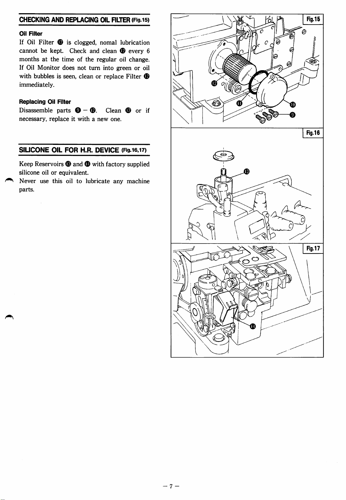
CHECKING
Oil
RIter
If
Oil
cannot
months
If
Oil
with
bubbles
immediately.
AND
Filter
be
kept.
at
the
Monitor
REPLAaNG
is
clogged,
Check
time
does
is
seen,
and
of
the
not
turn
clean
OIL
nLTER
nomal
(Fig.i5)
lubrication
clean ® every
regular
or
oil
into
green
replace
change.
Filter
or
6
oil
Replacing
Disassemble
necessary,
SlUCONE
Keep
silicone
^
Never
parts.
Oil
RIter
parts © —
replace
OIL
it
FOR
Reservoirs ® and © with
oil
or
equivalent.
use
this
oil
®.
with a new
H.R.
DEVICE
to
lubricate
Clean © or
factory
one.
(ng.i6.i7)
supplied
any
machine
if
- 7 -
Page 10
NEEDLES
Use
DCX27,
chainstitch
Note:
For
the
extra-heavy
overlock
double
•
ETS32-452BA2/,^}®-433
•
ETS32-452BA4/J
•
ETS32-453BA2/,cJ
•
ETS32-453BA4/|J5j-453
#11
for
needles.
following
fabrics),
needle
chainstitch
and
(OlD)
(515)
both
overlock
machines
use
DCX27,
needle.
DC
for
XI,
J|-433
rN-453
and
jeans
#21
#21
double
(for
for
for
the
the
Needle
Upper
according
Table
replaced
changed
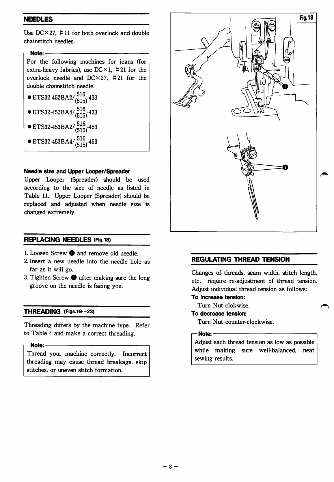
REPLACING
1.
2.
3.
THREADING
Threading
to
^
size
and
Looper
to
11.
Upper
and
extremely.
Loosen
Insert a new
far
Tighten
groove
Screw O and
as
it
will
Screw O after
on
differs
Table 4 and
Note:
Thread
threading
stitches,
your
may
or
uneven
Upper
(Spreader)
the
adjusted
NEEDLES
needle
go.
the
needle
(Fig8.i9~23)
make a correct
machine
cause
Looper/Spreader
should
size
of
needle
Looper
(Spreader)
when
(Rg
is)
remove
into
the
making
is
facing
by
the
machine
correctly.
thread
stitch
formation.
be
used
as
listed
should
needle
old
needle
you.
threading.
breakage,
size
needle.
hole
sure
the
type.
Refer
Incorrect
long
skip
in
be
is
as
REGULATING
Changes
etc.
Adjust
To
Turn
To
Turn
r-
Note:
Adjust
while
sewing
of
require
individual
increase
Nut
decrease
Nut
each
making
results.
THREAD
threads,
re-adjustment
thread
tension:
clokwise.
tension:
counter-clockwise.
thread
sure
TENSION
seam
width,
of
thread
tension
tension
well-balanced,
as
as
low
stitch
length,
tension.
follows:
as
possible
neat
- 8 -
Page 11
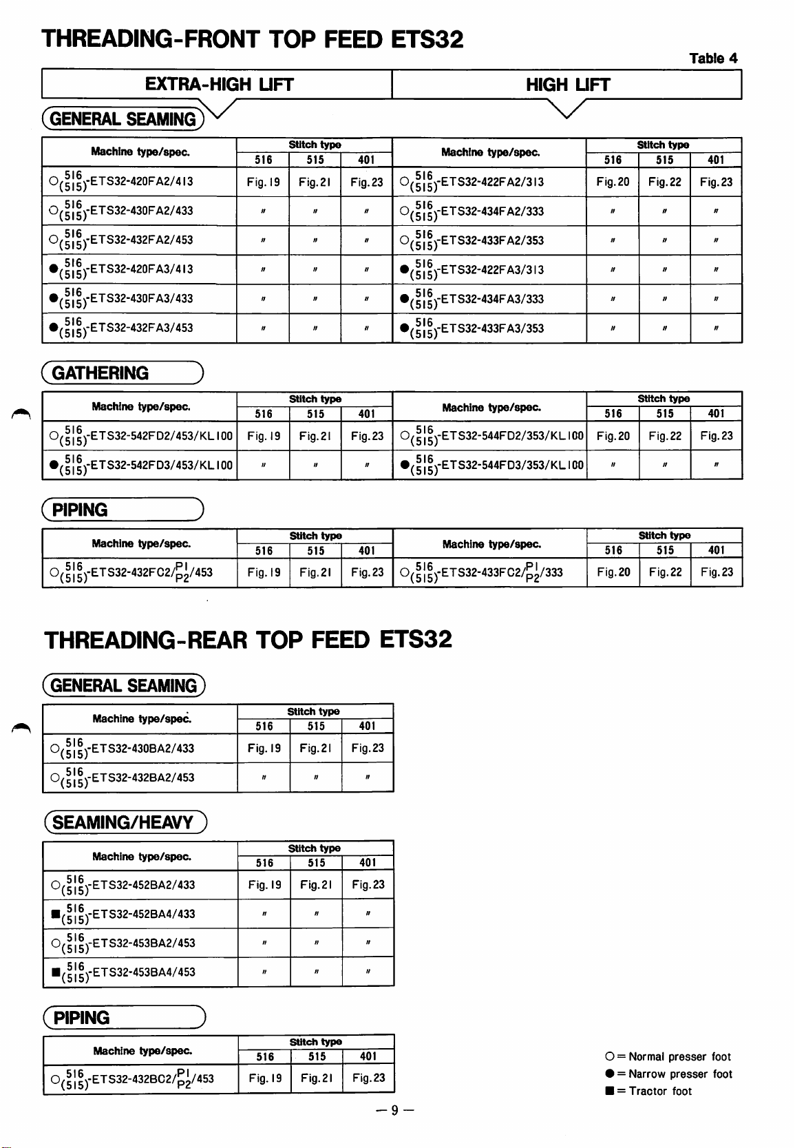
THREADING-FRONT
TOP
FEED
ETS32
Table
4
EXTRA-HIGH
(GENERAL
0(5 ] 5)-ETS32-420FA2/4
SEAMING
Machine
type/spec.
13
UFT
516
Fig.
19
Stitch
515
Fig.
0(5]5)"ETS32-430FA2/433
0(5]5)'ETS32-432FA2/453
516
'(515)"
^ ® J-ETS32-430FA3/433
•(5l5)-ETS32-432FA3/453
(gathering
Machine
0(
51 f )-ETS32-542FD2/453/KL
•(
51
5)-ETS32-542FD3/453/KL
type/spec.
)
100
100
516
Fig.
19
W
Stitch
515
Fig.
type
ft
21
type
21
401
Fig.
23
401
Fig.23
n
HIGH
Machine
O
(51
5)-ETS32-422F
516
O
0(|
ETS32-434FA2/333
(515)'
15
J-ETS32-433FA2/353
516
rETS32-422FA3/3l3
(515)"
type/spec.
A2/313
UFT
518
Fig.
20
Stitch
type
515
Fig. 22Fig.
•(5|5)-ETS32-434FA3/333
•(5]5)"ETS32-433FA3/353
Stitch
Machine
0(
51
5)-ETS32-544FD2/353/KL
•(51
5)-ETS32-544FD3/353/KL
type/spec.
516
Fig. 20Fig.22
100
100
ft
type
515
n
401
23
401
Fig.23
n
(
PIPING
Machine
0( ® 1
^)-ETS32-432FC2/^^/453
type/spec.
THREADING-REAR
(GENERAL
0(
51
5)-ETS32-430BA2/433
0(
51
5)-ETS32-432BA2/453
(SEAMING/HEAVY
SEAMING)
Machine
Machine
type/spec.
type/spec.
)
0(5l5)"ETS32-452BA2/433
■(
51
5)-ETS32-452BA4/433
0(51
5)-ETS32-453BA2/453
■JI5J-ETS32-453BA4/453
Stitch
516
Fig. 19Fig.2l
TOP
Stitch
516
Fig. 19Fig.21
ft
Stitch
516
Fig. 19Fig.
»
«
//
type
515
Fig.23
FEED
type
515
Fig.23
ft
type
515
Fig.23
2!
n
n
II
401
Machine
0(5l5)"ETS32-433FC2/p2/333
type/spec.
Fig.20
Stitch
516
ETS32
401
ft
401
ft
ft
ft
typo
515
Fig.22
401
Fig.23
(piping
Machine
1
®)-ETS32-432BC2/^^/453
type/spec.
J
516
Fig.
19
Stitch
Fig.2!
515
typo
401
Fig.23
-9
O = Normal
• = Narrow
■ = Tractor
presser
presser
foot
foot
foot
Page 12
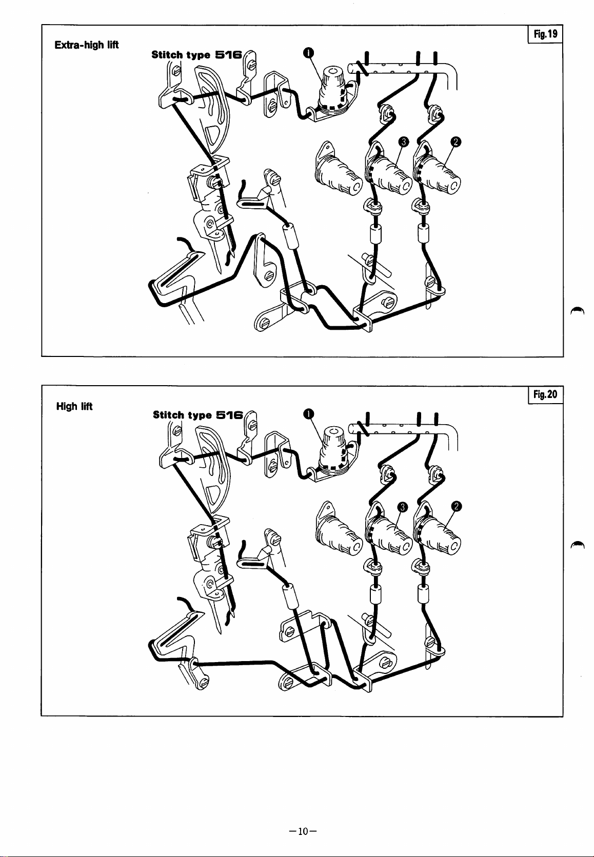
Extra-high
lift
Stitch
type
Rg.19
SIB
High
lift
Stitch
type
Fig.20
516
-10-
Page 13
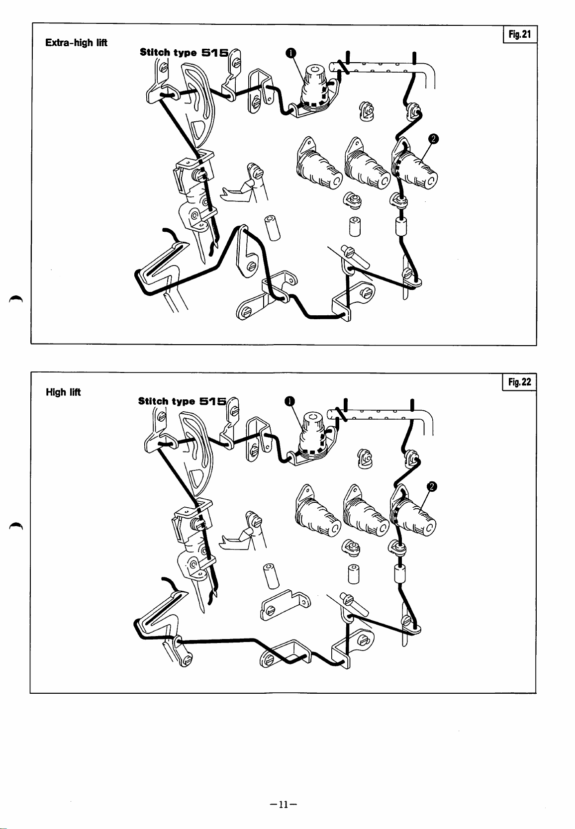
Extra-high
lift
Fig.21
Stitch
High
lift
Stitch
type
Fig.22
515
-11
Page 14
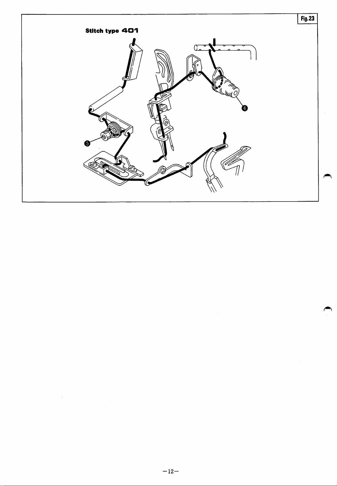
Fig.23
Stitch
type
401
-12-
Page 15

PRESSER
ARM
SWINGING-IN
AND
-0UT(Rg.24)
When
arm,
Swingfng-out
Open
the
only
this
Presser
Swinging-in
Press
Swinging-in
first
raise
Spring O in
foot
lifting
the
top
feed
position,
Arm O to
the
foot
Lever 0 and
Keeping
return
i—
Note:
Rear
CBC23
Raise
you
Arm
this
Presser
Top
Feed
in
the
the
needle
can
swing-in
O.
or
swinging-out
the
needle
the
treadle
dog
pull
up
the
lifting
the
top
position,
Arm O to
Machines
last 3 figures
to
to
the
arrowed
or
lower
will
be
Lever O and
left.
treadle
feed
pull
or
dog
up
the
shown
of
the
highest
or
swing
the
presser
highest
direction,
position.
press
Lever 0 and
raised.
Keeping
swing-out
lower
Foot
will
be
raised.
Lever O and
original
Type
position.
as
CBA2]
Plate:
position
out
and
Presser
Lift
or
PRESSER
To
adjust
Presser
possible,
and
foot
while
obtain
FOOT
the
pressure,
pressure
still
proper
PRESSURE
turn
should
sufficient
stitch
formation.
(Rg
Screw
be
to
25)
0.
as
light
feed
Fig.25
as
fabric
-13-
Page 16

STITCH
LENGTH ADJUSTMENT
(ng8.26,27)
While
Q
Turn O further
Release
For a longer
direction.
For a shorter
direction.
^Note:
HANDWHEEL
pressing
until
Button O drops
O.
stitch
The
stitch
nominal.
length
Table 5 shows
scale
setting.
an
approximate
MAIN
FEED
STROKE
SCALE
Handwheel
scale
setting
Main
feed
stroke
Push
for a desired
stitch
this
It
may
stitch
1
1.0
Button
O,
turn
in.
length,
length,
is
stroke
(mm)
SETTING
2
1.5
turn 0 in
turn 0 in
the
main
by
the
be a reference
length.
BY
THE
3
4
2.0
2.5
Handwheel
stitch
feed
stroke
handwheel
to
5
3.0
length.
the
(+)
the
(—)
in
know
Table
6
7
3.5
3.8
5
a
DIFFENTIAL
Loosen
To
direction.
To
direction.
I—
Nut
gather
stretch
Note:
0.
the
the
Table 6 shows
the
lever
setting.
When
differential
•
Lever 0 is
If
set
feed
higher
differential
Maximum
•
If
set
lower
feed
is
applied.
Maximum
FEED
fabric,
ADJUSTMENT
turn
fabric,
the
differential
set
ratio
than
feed
is
applied.
up
to 1 ^
than
(2),
up
to
11
Screw O in
turn
Screw O in
to
the
is 1 :
1.
(2),
0.7.
the
positive
2.
(Rg.28)
the
(+)
the
(—)
feed
ratio
scale
(2),
the
the
negative
differential
by
DIFFERENTIAL
Scale
on
indication
Differential
feed
ratio
FEED
plate
i:
RATIO
1
0.7
1:1
©
Table
6
2
3
1:1.4
4
1:1.7
5
1:2
-14-
Page 17

TOP
FEED
STROKE
ADJUSTMENT
(Fig.29)
Loosen
stroke
Nut © shift
will
Shift O in
will
increase.
Shift O in
will
decrease.
•
When
will
•
When
depending
ADJUSTING
For
Loosen
top
i—
•
•
•
seaming,
not
occur.
standard
Nut
feed
pressure
Notes:
Too
much
on
the
fabric.
Too
little
the
top
abnormal
Adjust
while
positive
Lever © and
be
changed.
the
(+)
direction,
the
(—)
direction,
adjust
shirring/adding
on
the
TOP
pressure
®,
turn
on
pressure
pressure
feed
noise.
the
pressure
feeding
so
that
fullness,
nature
FEED
of
PRESSURE
set
gap
the
Screw © and
the
fabric.
may
cause
may
cause
dog,
uneven
as
weak
should
the
and
and
the
fabrics.
(a)
to
feed
jumping
feeding
as
be
top
the
stroke
the
stroke
ply
adjust
(Fig.30)
25mm.
adjust
marking
possible
kept.
feed
shift
Q
Fig.30
the
(a)25<™fl
of
or
REGULATING
1.
Loosen
©
2.
Loosen
Screw
to
the
Screw © and
Clamp © to
seam
width
Tighten
3.
Turn
Knife
Plate
will
4.
Make
Tighten
5.
Check
thread
check
-
Note:
Needle
available.
of
width
Screw
Handwheel
is
top.
return
sure
Screw
Knives
between
the
Plates
the
proper
required.
SEAM
©,
left
and
the
is
obtained.
®.
about
Loosen
to
position.
Knives
®.
cut
Knives,
cutting
for
Best
results
size
WIDTH
push
lightly
right
or
so
that
l.Omm
Screw
are
in a perfect
sharply;
of
knives.
various
are
Needle
(Rgs.3i.32)
Lower
tighten
move
above
Knife
Screw
Upper
left
until a desired
the
point
from
©,
then
Holder
alignment.
insert a piece
turn
Handwheel
seam
widths
obtained
Plate
for
Holder
©.
Knife
'b'
Needle
with
seam
and
are
use
of
©
of
Fig.
32
-15-
Page 18

NEEDLE
The
guides
Refer
positions
For
adjust
THREAD
standard
O,
to
Table 7 and
to
adjusting,
Guides
GUIDE
SETTING
setting
positions
©, ® are
your
machine.
loosen
O,
®.
as
shown
set
them
Screws
POSITION
of
to
O,
(Fig.
needle
in
Table
the
correct
©, ® and
33)
thread
7.
LOOPER
THREAD
Check
for
the
Extra-high
1.
2.
3.
•
•
your
the
extra-high
high
lift
Looper
Loosen
lowest
Upper
Lower
When
point,
Guides
position
Looper
For
loosen
© ©
For
Thread
as
Thread
position.
Looper
Looper
the
loosen
©, © up
Thread
the
Screws
to
the
Guides © ©
(516).
THREAD
GUIDE
machine
machines.
Lift
(Fig.
Screw o and
lower
TAKEUP
SETTING
with
lift
machines.
34)
Guide
Thread
Thread
looper
Screws
O
Takeup
Takeup
and
shown
the
machines
in
Fig.
Guides
machines
© ©
positions
of
34.
of
and
indicated
the
to
AND
POSITIONS
Table
See
set
Guide O to
O,
<£)
is
at
the
(D,
®,
down
and
© ©
the
stitch
set
Thread
stitch
the
positions
LOOPER
7.
See
Fig.35
right
shift
Thread
set
type
Guides
as
(515).
type
516,
indicated
Fig.
for
the
dead
to
the
515,
set
34
A = Highest
B = Center
C - Lowest
Extra-high
lift
515
516
High
Lift
(Fig.35)
High
1.
Looper
Loosen
between
Thread
2.
Upper
Lower
When
point,
Takeups
position
3.
Looper
•
For
loosen
© ©
•
For
loosen
© ©
Thread
Screw © and
Guide © is
Looper
Looper
the
loosen
Bed
surface
Thread
Thread
lower
Screws
Guide
©, © up
as
shown
Thread
the
Screws © ©
to
the
Screws © ©
to
the
Guides
machines
the
positions
machines
positions
©
set
(a)
39.0mm.
Takeup
Takeup
looper
is
©.
and
down,
in
Fig.
© ©
of
the
and
indicated
of
the
and
indicated
that
and
©,
©
at
the
©,
adjust
35.
stitch
set
Thread
stitch
set
Thread
the
the
and
as
as
distance
hole
right
dead
Thread
set
at
type
515,
Guides
(515).
type
516,
Guides
(516).
of
the
lift
Bed
surface
(a)
Page 19

NEEDLE
THREAD
GUIDE
SETTING
POSITION-FRONT
TOP
FEED
ETS32
Table
7
EXTRA-HIGH
(GENERAL
0(51
5)-ETS32-420FA2/4
0(
51
5)-ETS32-430FA2/433
0(
51
5)-ETS32-432FA2/453
,
516
(515)'
,
516
(515)'
^ I ®
(gathering
0(51
5)-ETS32-542FD2/453/KL
•(
51
5)-ETS32-542FD3/453/KL
SEAMING)
Machine
type/spec.
13
•ETS32-420FA3/4I3
ETS32-430FA3/433
J-ETS32-432FA3/453
)
Machine
type/spec.
100
100
LIFT
Stitch
type
o
e
Stitch
type
O
e e
B B B B
//
n
516
516
//
stitch
type
O
®
Stitch
type
O
e e
A
ti
W
515
0(51|)-etS32-
0(51
515
0(
A
n
•(51
Machine
1
5)-ETS32-422FA2/3
type/spec.
434FA2/333
5)-ETS32-433FA2/353
>
516
ETS32-422FA3/3I3
(515)'
,
516
rETS32-434FA3/333
(515)'
,
516
,-ETS32-433FA3/353
(515)'
Machine
type/spec.
515yETS32-544FD2/353/KL
5)-ETS32-544FD3/353/KL
HIGH
13
LIFT
100
100
Stitch
type
Stitch
type
O
e
B
c
tl
tl
516
516
0
C
It
Stitch
type
stitch
type
o
0
c c
B
It
If
515
515
0
tl
(
PIPING
Stitch
Machine
type/spec.
0(5l5)"ETS32-432FC2/p2/453
NEEDLE
(general
0(51
5)-ETS32-430BA2/433
0(
51
5)-ETS32-432BA2/453
(seaming/heavy
0(51
5)-ETS32-452BA2/433
,
516
'{515)'
0(
51
5)-ETS32-453BA2/453
THREAD
seaming)
Machine
Machine
ETS32-452BA4/433
type/spec.
type/spec.
GUIDE
)
type
O
0
B B
Stitch
type
0
0 0
B
B
tl
Stitch
type
e
ft
Stitch
516
O
0
B
B
SETTING
Stitch
516
0
B
B
tl
tt tt
stitch
516
type
515
0
0
A
A
0(5'
Machine
5)-ETS32-433FC2/^^/333
POSITION-REAR
type
515
0
0
A
A
tt
type
515
type/spec.
TOP
Stitch
type
0
0
C C
B
FEED
516
Stitch
0 0
0
B
ETS32
type
C
515
0
C
l(^|5j-ETS32-453BA4/453
(
PIPING
Machine
0( ^ 1
®)-ETS32-432BC2/^^/453
type/spec.
J
Stitch
type
0
0
B
B
516
0
B
Stitch
type
0
0
B
515
0
A
A
-17-
O = Normal
• = Narrow
■ = Tractor
presser
presser
foot
foot
foot
Page 20

CHAiNSTITCH
HANDLING
(ng8.36.37)
LOOPER
THREAD
dlLooper
Adjust
Thread
the
gap
Bracket 0 and
Takeup
Loosen
m
When
adjust
Guide O to
Screw 0 and
Looper
Thread
the
the
needle
gap
Bracket 0 and
dimension
Loosen
dlLooper
Adjust
Bracket
Loosen
^
Note:
•
For
the
•
For
the
c)
to
6.5mm.
Screws 0 and
Thread
the
eye
0.
Screw 0 and
more
thread
(+)
direction.
less
thread
(—)
direction.
Takeup
Guide
between
the
tip
6.0 — 6.5mm.
adjust.
Takeup
is
at
O
the
between
tip
(b)
of
adjust.
Eyelets
of
Eyelet
adjust.
in
the
in
the
O
the
top
surface
of
Looper
upper
the
top
Takeup O (Fig.
i
to
seam,
seam,
Thread
dead
point,
surface
36,
mark
(d)
shift
shift 0 in
m
of
of
of
Fig.
37
©
CHANGING
1.
Loosen
0
2.
Remove
to
Screw
the
Replace
Adjust 0 so
for
the
seam
Upper
when
3.
Turn
Knife
Plate
Loosen
to
Make
and
Upper
Handwheel
is
top.
Screw
position.
sure
Tighten
4.
Check
thread
check
Knives
between
the
UPPER
0,
left
and
Screw
0.
Upper
that
width
Lower
Knife 0 is
about
0,
Knives
Screw
0.
cut
cutting
KNIFE
push
lightly
(Figs.
Lower
tighten
Knife 0 with
it
is
in
the
correct
and
also,
the
Knives
is
lowest.
so
that
the
1.0mm
Knives,
above
then
Holder 0 will
are
in a perfect
sharp;
of
insert a piece
turn
Knives.
Handwheel
38.39,40)
Knife
Holder
Screw
the
0.
new
one.
position
overlap
0.5 — 1.0mm
point
'e'
from
Needle
return
alignment.
of
of
of
and
Upper
knife
0.5~ I .0™n
Needle
top
surface
plate
Fig.
39
-18-
Lower
knife
Page 21

CHANGING
1.
Loosen
0
2.
Loosen
Replace
•
Move
edge
Tighten
3.
Turn
Upper
Needle
Screw
to
the
left,
Screw
Lower
Knife
is
level
Screw
Handwheel
Knife
Plate
Holder 0 will
4.
Make
sure
Tighten
5.
Check
thread
check
Screw
Knives
between
the
cutting
LOWER
0,
push
and
lightly
®.
Knife 0 with
up
or
with
Needle
0.
so
is
about
top.
return
Knives
are
0.
cut
sharp;
Knives,
of
Knives.
KNIFE
(Fig8.40,4i)
Lower
Knife
tighten
the
down
Loosen
to
until
Plate
top.
that
the
point
l.Omm
above
Screw
position.
in a perfect
insert a piece
turn
Handwheel
Holder
Screw
new
its
0.
one.
cutting
'e'
of
from
0,
then
alignment.
of
and
Needle
top
surface
plate
KNIVES
Knives
If
the
sharpen
Sharpening
Sharpen
Upper
Upper
returned
special
(Fig.42)
must
be
machine
the
lower
Lower
the
lower
Knife
Knife
may
to
us
grinding.
kept
sharp.
does
not
trim
knife.
Knife
0
knife
as
be
sent
for
resharpening
the
fabric
specified
to
our
distributors
since
sharply,
in
Fig.
it
requires
42.
or
-19-
Page 22

BOTTOM
FEED
HEIGHT
(Rgs.43.44)
Fig.43
Bottom
Table
to
1.
2.
3.
feed
8.
Make
your
machine.
Turn
the
dog
to
the
Adjust
needle
of
the
For
Main
Set
gap
plate
the
main
type.
adjusting,
Feed
the
tooth
Dog ® to
(c)
of
the
For
adjusting,
dog
hand
highest
the
main
Differential
height
sure
that
wheel
(a)
to
feed
position.
from
the
tooth
dog
to
to
loosen
Dog O up
end
(b)
same
height
feed
dog.
loosen
Feed
Dog 0 up
by
type
is
as
shown
the
lift
the
end
the
setting
the
top
height
of
the
is
bottom
face
rear
correct
Screw O and
and
down.
of
Differential
as
the
tooth
Screw O and
and
down.
in
correct
feed
of
the
part
to
shift
Feed
end
shift
(a)
(c) (b)
AUXILIARY
Gap
(d)
dog
to
is
adjusted
Generally,
wider,
smaller.
To
adjust
Auxiliary
BOTTOM
from
the
and
Feed
FEED
the
tooth
to
the
for
using
for
using
the
gap,
Dog 0 up
FEED
ADJUSTMENT
Adjust
the
appear.
For
Screw
so
that
all
needle
adjusting,
0,
plate
and
turn
remove
DOG
HEIGHT
tooth
end
of
the
end
of
Auxiliary
machine
type.
coarse
finer
loosen
and
LEVELING
thread,
thread,
Screw ® and
Feed
down.
POSITION
(Figs.46.47)
the
teeth
ends
are
top
surface
cover
Washer
when
plate
0
(Fig.45)
main
Dog
set
the
set
the
shift
flush
they
O,
loosen
feed
©
gap
gap
with
first
p
Needle
top
surface
Fig.45
Flg.46
plate
f—
Note:
1.
For
hold
so
2.
Be
after
tightening
the
as
to
avoid
sure
the
Screw 0 after
feed
bar
exactly
sidewise
to
adjust
adjustment.
with
shifting.
"bottom
adjustment,
Washer
feed
0
height"
-20-
Page 23

BOTTOM
FEED
HEIGHT-FRONT
TOP
FEED
ETS32
Table
8
EXTRA-HIGH
(GENERAL
SEAMING)
Machine
type/spec.
O(^|^)-ETS32-420FA2/4I3
0(11
5)-ETS32-430FA2/433
O
J15
J-ETS32-432F
A2/453
•(5l5)"ETS32-420FA3/4l3
51
5)-ETS32-430FA3/433
•(5 ] 5)-ETS32-432FA3/453
(gathering
Machine
0(11
^)-ETS32-542FD2/453/KL
type/spec.
)
i
•(5l5)"ETS32-542FD3/453/KLI00
00
UFT
Bottom
Bottom
feed
0.9-1
feed
0.9-l
height
.1
//
//
//
H
ft
height
.i
ft
HIGH
Machine
^(51
5)-ETS32-422FA2/3
type/spec.
i
0(^l®)-ETS32-434FA2/333
0( 5 ] 5 J-ETS32-433F
A2/353
•(5l5)'ETS32-422FA3/3l3
•(51
5)-ETS32-434FA3/333
•(5|5)-ETS32-433FA3/353
Machine
0(
51
5)-ETS32-544FD2/353/KL
•(51
5)-ETS32-544FD3/353/KL
type/spec.
3
UFT
100
100
o
Bottom
0.8~i
Bottom
0.8-1.0
I
00
feed
n
ft
u
ft
ft
feed
ft
O
height
.0
height
(PIPING
Machine
type/spec.
0(^]^)-ETS32-432FC2/^^/453
BOTTOM
(general
seaming)
Machine
type/spec.
0( ^ 1 ^ J-ETS32-430BA2/433
0(5l5)"ETS32-432BA2/453
(seaming/heavy
Machine
0(51
5)-ETS32-452BA2/433
■(
51
^)-ETS32-452BA4/433
type/spec.
)
FEED
)
Bottom
feed
height
0.9-1.1
HEIGHT-REAR
Bottom
feed
height
0.9-i.
Bottom
0.9-1.1
ft
feed
//
l
height
Bottom
feed
Machine
type/spec.
height
0(5|5)-ETS32-433FC2/p2/333
TOP
FEED
ETS32
0(5l5)"ETS32-453BA2/453
■(51
5)-ETS32-453BA4/453
(PIPING
Machine
type/spec.
)
Bottom
0(^ 1 ^)-ETS32-432BC2/^^/453
tf
tf
feed
0.9-i.l
height
-21-
O = Normal
• = Narrow
■ = Tractor
presser
presser
foot
foot
foot
Page 24

NEEDLE
HEIGHT
SETTING
(Fi98.48.49)
Fig.48
Table 9 shows
each
machine
Make
sure
machine.
To
adjust
1.
Turn
the
highest
2.
Measure
the
needle
and
adjust
dimension.
For
adjusting,
Needle
f—
Note:
Make
sure
the
center
plate.
If
necessary,
Needle
type.
that
the
hand
level.
gap
plate
the
Holder
that
of
Holder 0 and
the
correct
the
setting
wheel
(a)
between
top
needle
loosen
Guide
the
chainstitch
the
needle
loosen
needle
is
and
bring
the
surface
height
height
correct
the
needle
needle
point
perpendicularly
to
the
Screw O and
©.
needle
hole
of
the
Screw 0 and
adjust.
for
for
your
and
correct
adjust
passes
needle
turn
to
Flg.49
LOWER
LOOPER
Table 9 shows
for
each
machine
setting
To
1.With
is
correct
adjust:
the
needle
0 — 0.05mm
comes
For
Looper
2.
When
point,
and
dimension.
For
Looper
to
the
adjusting,
Holder O back
the
lower
adjust
the
needle
adjusting,
Holder O to
the
correct
type.
for
bent
center
loosen
gap
(b)
loosen
SETTING
by
(Rgs.50,51)
lower
Make
your
machine.
guard
the
of
the
idle,
looper
needle.
Screw 0 and
and
forth.
looper
is
at
between
centerline
Screw 0 and
the
right
looper
sure
set
point
the
the
looper
to
the
or
left.
that
the
when
left
setting
the
needle
it
shift
dead
point
correct
shift
0 ~ 0.05"""
Fig.
50
Rg.51
-22-
Page 25

NEEDLE
HEIGHT/LOWER
EXTRA-HIGH
UFT
LOOPER
SETTING-FRONT
HIGH
TOP
UFT
FEED
ETS32
Table
9
(GENERAL
0(^ 1 ^)-ETS32-420FA2/413
O(^|^)-ETS32-430FA2/433
0(^l^)-ETS32-432FA2/453
•(51
5)-E"''S32-420FA3/4
•(
51
5)-ETS32-430FA3/433
•(
51
5)-ETS32-432F
(GATHERING
0(5 ] 5)-ETS32-542FD2/453/KL
•(11
1)"ETS32-542FD3/453/KL
(
PIPING
SEAMING)
Machine
Machine
type/spec.
type/spec.
13
A3/453
)
100
100
Needle
(a)
11.7-11.9
//
tf
//
//
//
Needle
(a)
11.7-11
ff
Lower
Lower
.9
looper
(b)
3.6--3.9
//
//
n
n
//
looper
(b)
3.6-3.9
//
Machine
type/spec.
0(5|5)"ETS32-422FA2/3I3
0(®j®)-ETS32-434FA2/333
0( 5 ]
5)-ETS32-433F
•(51
5)-ETS32-422FA3/3
•(11
5)-ETS32-434FA3/333
•(11
5)-ETS32-433FA3/353
Machine
0(515
J-ETS32-544FD2/353/KL100
•(515
J-ETS32-544FD3/353/KLI00
A2/353
13
type/spec.
Needle
(a)
I0.4~i0.6
n
//
//
n
//
Needle
(a)
10.4-10.6
it
Lower
3.8-4.1
Lower
3.8-4.
loopor
(b)
ff
n
n
n
n
looper
(b)
ft
1
Machine
0(^1
5)-ETS32-432FC2/^^/453
NEEDLE
(GENERAL
Machine
0(51
5)-ETS32-430BA2/433
0(
51
5)-ETS32-432BA2/453
(SEAMING/HEAVY
Machine
type/spec.
HEIGHT/LOWER
SEAMING)
type/spec.
)
type/spec.
0(5l5)'ETS32-452BA2/433
■(1|5)-ETS32-452BA4/433
Needle
(a)
II.7-11.9
Needle
(a)
II.7-11.9
if
Needle
(a)
II.7-11.9
tt
LOOPER
Lower
3.6-3.9
Lower
3.6-3.9
Lower
3.6-3.9
looper
(b)
0( 1 ]
Machine
ETS32-433FC2/^2/333
SETTING-REAR
looper
(b)
it
looper
(b)
it
type/spec.
TOP
Needle
(a)
10.4-10.6
FEED
Lower
(b)
ETS32
CO
00
1
loopor
Lower
3.6-3.9
tt
tt
(b)
looper
-23-
0(|]5j-ETS32-453BA2/453
51 ® J-ETS32-453BA4/453
(
PIPING
Machine
type/spec.
J
0(5l5)"ETS32-432BC2/p2/453
if
a
Needle
(a)
II.7-11.9
0=
Normal
• = Narrow
■ = Traotor
presser
presser
foot
foot
foot
Page 26

UPPER
The
Make
machine.
1.
2.
3.
(c)
LOOPER
standard
sure
that
Tentatively
Screw
When
adjust
Loosen
and
When
check
0.5mm.
Tighten
0.
the
gap
(a)
Screw
adjust
the
that
Turn
to
approximately
Screws 0 and
SETTING
setting
set
looper
this.
upper
clearance
the
the
to
the
®,
the
move
looper
is
setting
is
and
(ng8.52-57)
as
shown
is
correct
looper
at
correct
in
the
left
dimension.
Crank O up
lower
(b)
is
and
adjust
0.2mm.
0.
in
Table
for
10.
your
Holder O by
dead
point,
or
down,
loopers
approximately
cross,
clearance
Extra-high
High
lift
lift
Rg.52
Fig.
53
Fig.
57
Extra-high
(a)4.5--5.0mm
High
lift
(a)4.5~5.Qmm
lift
(a)4.5~
(a)4.5~5.0mm
5.0mm
(c)
0.2mm
-24-
Rg.56
(b)0.5mm
Page 27

UPPER
LOOPER
SETTING-FRONT
TOP
FEED
TYPE
ETS32
Table
10
EXTRA-HIGH
(GENERAL
SEAMING)
Machine
type/spec.
O(^|^)-ETS32-420FA2/4I3
O(5l5)'ETS32-430FA2/433
0(^1
^)-ETS32-432FA2/453
•(5|5)-ETS32-420FA3/4I3
•
J1 ^ J-ETS32-430FA3/433
•
J15
J-ETS32-432F
(GATHERING
Machine
0(51
5)-ETS32-542FD2/453/KL
•(11
5)-ETS32-542FD3/453/KL
A3/453
)
type/spec.
100
100
UFT
Position
A
//
//
tf
ff
ff
Position
A
ff
Distance
Distance
(a)
4.5-5.0
ft
ft
ft
tt
tf
(a)
4.5-5.0
HIGH
Machine
type/spec.
0(5l5)-ETS32-422FA2/3i3
51
5)-ETS32-434F
A2/333
0(5l5)"ETS32-433FA2/353
•(5|5)-ETS32-422FA3/3I3
•(5l5)-ETS32-434FA3/333
•(5 j 5)-ETS32-433FA3/353
Machine
0(51
5)-ETS32-544FD2/353/KL
•(51
5)"ETS32-544FD3/353/KL
type/spec.
UFT
100
100
Position
B
//
tt
tt tt
tt
tf
Position
B
II
Distance
4.5-5.0
Distance
4.5-5.0
(a)
//
tt
tt
tt
(a)
//
(PIPING
Machine
0(
51
5)-ETS32-432FC2/^^/453
UPPER
(general
Machine
type/spec.
LOOPER
seaming)
type/spec.
0(515J-ETS32-430BA2/433
0(
51
5)"ETS32-432BA2/453
(SEAMING/HEAVY
Machine
515
J-ETS32-452BA2/433
type/spec.
■(5l5)'ETS32-452BA4/433
)
Position
A
SETTING-REAR
Position
A
ff
)
Position
A
tt
Distance
Distance
(a)
4.5-5.0
(a)
4.5-5.0
tt
Distance
(a)
4.5-5.0
ff
Machine
0(51
5)-ETS32-433FC2/^^/333
TOP
type/spec.
FEED
TYPE
Position
B
ETS32
Distance
(a)
4.5-5.0
0(5! 5 )-ET
(
PIPING
0(
S32-453B
5 ] 5
J-ETS32-453BA4/453
A2/453
J
Machine
type/spec.
515)-ETS32-432BC2/p2/453
ff
tf
Position
A
tf
tf
Distance
4.5-5.0
(a)
-25-
O = Normal
• = Narrow presser
■ = Tractor
presser
foot
foot
foot
Page 28

CHAINSTiTCH
1.
Set
the
looper
Fig.
58.
•
At
the
factory,
this
by
the
looper
Insert
regulator
2.
When
its
the
dimension:
•
(a)
•
(a)
Loosen
3.
Distance
When
distance
needle
Loosen
shank.
the
O.
the
point
needle,
is
0~
0.05mm
is
0~0.1mm
Screw o and
from
the
between
centerline
Screw O and
LOOPER
in
the
the
regulator
looper
comes
looper
until
looper
behind
adjust
for
for
needle
is
moves
at
the
should
SETTING
holder
looper
O,
located
its
shank
to
the
gap
(a)
needles
needles
adjust
the
Looper
left
looper
be
1:67-1.8mm.
adjust
Looper
(Fig8.58~6i)
as
shown
is
adjusted
below
touches
the
right
centerline
to
the
correct
#16
or
thinner.
#17
or
thicker.
Holder
dead
point,
point
and
Holder
in
like
the
the
and
of
©.
the
the
®.
Rg.58
59.5"™
Hg.59
4.
Looper
Adjust
to
Loosen
•
For a thinner
•
For a thicker
avoiding
the
the
needle
Nut O and
looper
motion
avoiding
size.
move
needle,
needle,
move
motion
according
Pin 0 up
move
Pin 0 upward.
Pin 0 downward.
or
down.
1
.6— I .Bntm
Fig.
60
-26-
€
Page 29

OVERLOCK
SETTING
(Rgs.62--66)
NEEDLE
GUARD
Overlook
•
Movable
When
needle
the
the
Loosen
Overlook
When
needle
Needle
0.1 ~ 0.2mm.
Loosen
the
centerline,
needle
looper
Screw 0 and
Needle
the
centerline,
Guard O and
Screw o and
Needle
Guard
type
lower
so
that
point
and
Guard
lower
(rear)
looper
Needle
Guard O should
the
clearance
the
needle
adjust.
(front)
looper
the
clearance
the
adjust.
setting
point
is
is
setting
point
is
needle
O
behind
(b)
between
0mm,
O
behind
(c)
between
should
the
push
the
be
Overlook
•
Solid
When
needle
the
the
Loosen
Overlook
When
needle
Needle
0.1 ~ 0.2mm.
Loosen
Needle
type
the
centerline,
needle
looper
Screw 0 and
Needle
the
centerline,
Guard
Screw O and
lower
so
that
point
and
lower
Guard
(rear)
looper
Needle
the
the
adjust.
Guard
(front)
looper
the
and
adjust.
setting
point
is
Guard
clearance
needle
<D
is
(d)
0mm.
setting
point
is
clearance
the
(e)
needle
(D
behind
should
push
between
O
behind
between
should
the
the
be
(b)Onim
WO
0.2nmi
(d)Omm
-27-
(e)0.
1~0.2mm
Page 30

CHAINSTITCH
SETTING
(ng8.67,68)
NEEDLE
GUARD
Chainstitch
When
clearance
the
needle
Loosen
I—
Note:
If
Needle
heavy
chainstitch
wide
may
Chainstitch
When
clearance
needle
Loosen
Needle
the
needle
(a)
between
should
Screw O and
Guard O pushes
and
needle
(more
be
than
caused.
Needle
the
needle
between
should
be
Screw O and
Guard
(rear)
is
in
the
lowest
Needle
be
Omm.
adjust.
the
clearance
and
looper
0.05mm), a skip
Guard
(front)
is
in
the
lowest
Needle
0.05—0.1mm.
adjust.
setting
O
position,
Guard O and
the
needle
between
becomes
stitching
setting
0
position,
Guard 0 and
the
too
the
too
the
the
(a)
Omm
(b)0.05~0.
Fig.
68
Imm
NEEDLE
Stitch
515
516
SIZE
type
AND
UPPER
Needle
size
9-12
13-16
17-21
9-12
13-16
17-21
LOOPER/SPREADER
High
lift
Part
No.
210515
210514
210513
210366
210367
210365
(#27)
(#25)
(#23)
(#26)
(#28)
(#24)
Table
Extra-high
Part
211845
211719
lift
No.
(#29)
H
n
(#38)
//
it
11
-28-
Page 31

ADJUSTING
OF
BOTTOM
Set
Pin 0 and
Be
careful
To
adjust,
W
Limit
by
Stoppers 0 and
To
adjust,
THE
FEED
to
loosen
the
shifting
loosen
LENGTHWISE
DOGS
Washer © as
their
(Rg8.69-73)
direction
Nut
O-
range
of
0.
Screws 0 and
POSITION
shown.
and
position.
Lever ® to 1 —
0.
Fig.
5
70
Raise
Lever 0 and
Feed
Dog 0 to
setting = 1.
To
adjust,
When
Main
0
are
at
to
0.5mm.
To
adjust,
loosen
Feed
the
front
loosen
adjust
the
Nut
Dog 0 and
dead
the
stroke
minimum.
0.
Diff.
point,
Screw 0 and
of
The
Feed
adjust
move
gap
Crank
Diff.
lever
Dog
(c)
Fig.
73
(c)0.5'nfn
w
Set
the
stitch
Feed
Dog ® to
The
handwheel
w
When
search a position
Feed
Lever 0 up
To
the
Dog 0 does
adjust,
length
the
scale = 7.
feed
dogs
or
down.
loosen
or
the
stroke
maximum.
are
at
the
of
Crank 0 where
not
move
even
Screw
0.
end
if
of
of
stroke,
Diff.
you
Main
move
OOOl
\
W
-29-
Page 32

ADJUSTING
TOP
FEED
Table
feed
and
Make
machine.
For
Pin
SETTING
12
shows
dog
and
Crank
sure
adjusting,
O.
POSITIGN
VEffTTICAL
DOG
(Fig.74)
the
standard
the
gap
Pin 0 for
that
the
setting
loosen
OF
STROKE
stroke
(a)
between
each
machine
is
correct
Screw O and
TOP
FEED
DOG
OF
of
the
Crank
type.
for
shift
Crank
(ng.75)
top
O
your
a\(
a
Fig.
75
Table
feed
Make
machine.
ADJUSTING
OF
To
dog.
1.
2.
3.
12
shows
dog
for
sure
TOP
FEED
adjust
Pressing
and
set
Release
turn
the
dog
to
the
Make
sure
by
shifting
back
and
the
standard
each
machine
that
the
THE
LENGTHWISE
DOG
the
lengthwise
Push
Button
the
scale
to
your
hand
handwheel
rear
dead
that
the
Top
forth.
setting
type.
setting
is
correct
(ng8.76-78)
position
O,
turn
the
4.
from
the
bush
and
bring
the
point.
feed
dog
stands
Feed
Adjusting
of
the
for
your
POSITION
of
top
hand
wheel
button,
top
feed
still
even
Lever
top
A = Highest
B = Center
C = Lowest
feed
0
-30-
Page 33

TOP
FEED
FRONT
VERTICAL
TOP
FEED
STROTE
ETS32
AND
SET
POSITION-
Table
12
EXTRA-HIGH
(GENERAL
0(515
SEAMING
Machine
type/spec.
J-ETS32-420FA2/413
O(5l5)"ETS32-430FA2/433
0(^j®)-ETS32-432FA2/453
•(5|5)-ETS32-420FA3/4I3
•(5
l|)-ETS32-430FA3/433
•(5l5)'ETS32-432FA3/453
(GATHERING
Machine
0(
51
5)-ETS32-542FD2/453/KL
type/spec.
^ 1 ®)-ETS32-542FD3/453/KL
)
100
100
UFT
Stroke
4.5
//
//
//
n
n
Stroke
4.5
tl
Gap
1
Gap
1
(a)
.5
n
H
n
n
tt
(a)
.5
II
Position
A
//
W
U
n
If
Position
B
tt
HIGH
Machine
O
(515
J-ETS32-422F
0(5
||)-ETS32-434FA2/333
type/spec.
A2/313
0(^l®)-ETS32-433FA2/353
•(^]®j-ETS32-422FA3/3l3
•(51
5)-ETS32-434FA3/333
•(51
5)-ETS32-433F
Machine
A3/353
type/spec.
0(5]5)-ETS32-544FD2/353/KLIOO
•(51
5)-ETS32-544FD3/353/KL
UFT
100
Stroke
4.5
n
tt tt
tt tt
ft
tt
Stroke
4.5
tt
Gap
1
Gap
1
.5
tt
tt
tt
.5
tt
(a)
(a)
Position
A
If
If
tt
tt
Position
B
tt
C
PIPING
Machine
type/spec.
0(®|®j-ETS32-432FC2/^^/453
TOP
REAR
(GENERAL
FEED
TOP
SEAMING)
Machine
type/spec.
O(5|5)-ETS32-430BA2/433
O
(11
^)-ETS32-432BA2/453
(SEAMING/HEAVY
Machine
0(
515
J-ETS32-452BA2/433
type/spec.
■(5l5)"ETS32-452BA4/433
J
Stroke
VERTICAL
FEED
ETS32
Stroke
)
Stroke
4.5
STROKE
4.5
It
7.0
tt
Gap
1.5
Gap
4.0
Gap
8.0
(a)
(a)
11
(a)
tt
Position
Position
Position
Machine
A
0(515j-ETS32-433FC2/p2/333
AND
C
//
C
tt
SET
type/spec.
POSITION-
Stroke
4.5
Gap
1
(a)
.5
Position
A
0(
515
■
(515
(
PIPING
0(515
tt
Stroke
4.5
ft
Gap
J-ETS32-453BA2/453
)-ETS32-453BA4/453
Machine
type/spec.
j-ETS32-432BC2/p2/453
It
It
(a)
4.0
tt
tt
Position
C
-31-
O = Normal
# = Narrow
■ = Traotor
presser
presser
foot
foot
foot
Page 34

TOP
FEED
FEED
The
Make
machine.
Using
shifting
Loosen
RATIO
standard
sure
Stopper
range.
Screw
STROKE
(Fig.79)
setting
that
the
®,
set
o.
move
AND
DIFF.
is
as
shown
setting
is
correct
Lever O in
Stopper ® and
in
Table
the
13.
for
your
correct
adjust.
Rg.79
-=i
Q
-32-
Page 35

TOP
FEED
STROKE
AND
TOP
FEED
RATIO-FRONT
TOP
FEED
ETS32
Table
13
EXTRA-HIGH
(GENERAL
SEAMING
Machine
type/spec.
0(5 ] 5J-ETS32-420FA2/413
]
5)-ETS32-430FA2/433
0(51
5)-ETS32-432FA2/453
UFT
Sroke
2.8-5.8
•(5l5)'ETS32-420FA3/4l3
•(5l5)"ETS32-430FA3/433
,
516
ETS32-432FA3/453
^515)'
(GATHERING
Machine
0(51
5)"ETS32-542FD2/453/KL
•(51
5)-ETS32-542FD3/453/KL
type/spec.
)
100
100
Stroke
2.8-7.4
/;
Feed
ratio
1
:0.75
~i:
Feed
ratio
i:o.75
-i;
i.5
Setting
l~6
HIGH
Machine
type/spec.
■0(5|5)-ETS32-422FA2/3I3
^(51
5)-ETS32-434FA2/333
UFT
Stroke
2.8-5.8
Food
ratio
1:0.75
~i:i.5
Setting
1-6
0(m)-ETS32-433FA2/353
•(51
5)-ETS32-422FA3/3
.
516
ETS32-434FA3/333
(515)"
•(51
5)-ETS32-433FA3/353
Setting
1-9
i.95
H
11
Machine
type/spec.
O(^l^)-ETS32-544FD2/353/KLI00
•(^l^)-ETS32-544FD3/353/KLI00
13
Stroke
2.8-1
Feed
ratio
i:0.75
A
-i:
n
Setting
1-9
i.95
n
t!
Cpiping
Machine
0( ^ ]
^)-ETS32-432FC2/^^/453
TOP
FEED
(general
Machine
type/spec.
SEAMING)
type/spec.
O(5l5)"ETS32-430BA2/433
0(5l5)-ETS32-432BA2/453
(SEAMING/HEAVY
Machine
type/spec.
)
STROKE
)
00
ni
1
00
Stroke
CS
J
2.8-5.8
AND
Stroke
2.8-5.8
//
Stroke
0(5l5)'ETS32-452BA2/433
■(5l5)'ETS32-452BA4/433
II
Feed
ratio
1:
0.75
-i:
1.5
TOP
Food
ratio
i:0.75
-i:
i.95
n
Feed
ratio
1
:0.75
-i:i.95
;/
Setting
1-6
FEED
Setting
1-6
ft
Setting
1-6
//
Machine
0(®|®j-ETS32-433FC2/^^/333
RATIO-REAR
type/spec.
TOP
Stroke
2.8-5.8
FEED
Feed
ratio
i
:o.75
-i:i.5
ETS32
Setting
1-6
0( 5 j
®)-ETS32-453BA2/453
■
(11 ® J-ETS32-453BA4/453
(
PIPING
Machine
type/spec.
1 ® j-ETS32-432BC2/^^/453
J
2.8-5.8
II
Stroke
n
Feed
ratio
i:o.75
-i:
ft
1.95
II
ft
tt
Setting
1-6
-33-
O = Normal
• = Narrow
■ = Traotor
presser
presser
foot
foot
foot
Page 36

ADJUSTING
OF
TOP
FEED
The
standard
Make
sure
machine.
To
adjust
1.
Pressing
and
set
2.
Shift
Top
back
extremely
the
top
feed
3.
Turn
the
Dog O to
4.
Adjust
correct
Feed
plate.
gap
dimension.
Dog ® and
Loosen
and
adjust.
THE
DOG
setting
that
the
Push
Button
the
stitch
Feed
in
stroke
handwheel
the
front
(a)
Screw
O,
LENGTHWISE
(Figs,
so-83)
is
as
shown
setting
length
Adjusting
the
between
(B)
(A)
O,
to
(+)
to
the
and
dead
(A)
is
the
is
move
is
turn
maximum.
point.
that
Top
POSITION
in
Table
correct
the
Lever O to
direction,
bring
and
front
for
the
handwheel
maximum.
and
Top
(B)
tip
of
the
Feed
Bar
to
of
needle
14.
your
the
set
Feed
the
Top
©
m
ADJUSTING
OF
TOP
FEED
The
standard
Make
sure
machine.
To
adjust:
1.
Turn
the
feed
dog
2.
Loosen
3.
Move
the
feed
to
4.
When
fixed,
and
The
show
direction ( —)
the
Screws
Top
gap
between
dog
and
the
correct
the
clamp
©,
and
marks
the
bottom
THE
SIDEWISE
DOG
setting
that
the
setting
handwheel
to
the
bottom
©,
o
Feed
Dog © sidewise
the
the
left
height.
position
the
top
tighten
(+)
and
right
direction
based
feed
dog.
(Fig.
84)
is
as
shown
is
and
bring
dead
left
end
end
of
of
the
feed
bar
Screws
(-)
on
©,
listed
(+)
the
left
POSITION
in
Table
correct
point.
for
the
and
of
the
the
top
feed
top
feed
with
Guides
O.
in
Table
and
the
end
face
14.
your
bottom
adjust
bottom
dog
dog
is
©
16
left
of
HK®
—H-e
a
Page 37

HORIZONTAL
TOP
FEED
POSITION-FRONT
TOP
FEED
ETS32
Table
14
EXTRA-HIGH
(GENERAL
SEAMING)
Machine
type/spec.
O(^l^)-ETS32-420FA2/4I3
O(^l^)-ETS32-430FA2/433
0( ^ ] 5 J-ETS32-432FA2/453
•(5l5)-ETS32-420FA3/4l3
•(5 ] 5)'ETS32-430FA3/433
•(51
5)-ETS32-432FA3/453
(GATHERING
Machine
type/spec.
)
O(^|5)-ETS32-542FD2/453/KLI00
•(5]|j-ETS32-542FD3/453/KLI00
UFT
Back
and
position
(a)
II.0
w
w
12.5
n
II
Back
and
position
(a)
10.0
1
1.5
forth
forth
Right
to
position
-0.6
+ 1.6
W
+2.05
+4.25
//
Right
to
position
+ 1.6
+4.25
left
left
HIGH
Machine
0(
51
5)-ETS32-422F
0(51
5)-ETS32-434FA2/333
type/spec.
A2/313
0(®|®j-ETS32-433FA2/353
•(5
l|)-ETS32-422FA3/313
•(^|®j-ETS32-434FA3/333
•(51
5)-ETS32-433FA3/353
Machine
0(515
J-ETS32-544FD2/353/KL100
•(515
J-ETS32-544FD3/353/KL100
type/spec.
UFT
Back
position
Back
position
and
I I
.0
tf
ft
12.5
n
n
and
10.0
1
1.5
(a)
(a)
forth
forth
Right
position
Right
position
to
-0.6
+ 1.6
//
+2.05
+4.25
//
to
+ 1.6
+4.25
left
left
(PIPING
Machine
type/spec.
0(^]^)-ETS32-432FC2/^^/453
HORIZONTAL
(GENERAL
SEAMING)
Machine
type/spec.
O(®]^)-ETS32-430BA2/433
0(
51
5)-ETS32-432BA2/453
(seaming/heavy
Machine
0(
51
5)-ETS32-452BA2/433
type/spec.
J
TOP
)
Back
and
position
(a)
II.0
FEED
Back
and
position
(a)
43.5
tf
Back
and
position
(a)
43.5
forth
Right
position
+
POSITION-REAR
forth
Right
position
-0.3
Right
forth
position
-0.3
to
1.6
to
ft
to
left
ieft
left
Back
Machine
0(| ] 5
j-ETS32-433FC2/p2/333
type/spec.
TOP
FEED
and
position
I
I.0
ETS32
(a)
forth
Right
to
pc^tion
+ 1.6
ieft
+
-0.3
+3.8
Right
position
-0.3
3.8
to
left
-35-
Back
position
47.0
43.5
47.0
and
43.5
(a)
forth
■(^]^)-ETS32-452BA4/433
0(51
5)-ETS32-453BA2/453
■(5l5)"ETS32-453BA4/453
Cpiping
Machine
type/spec.
J
0(^||)-ETS32-432BC2/^^/453
O = Normal
• = Narrow
■ = Tractor
presser
presser
foot
foot
foot
Page 38

ADJUSTING
The
standard
Make
machine.
|—Note:
Be
sure
upper
dog.
sure
to
or
TOP
setting
that
the
check
lower
FEED
is
setting
your
dead
DOG
HEIGHT
as
shown
is
machine
point
of
(Figass^ss)
in
Table
correct
at
either
the
to
top
15.
your
the
feed
(a)25™n
Adjustments
•
Lower
is
1.
Loosen
gap
2.
Make
the
3.
Lower
and
feed
For
dead
in
the
lowest
Nut
(a)
to
sure
correct
Top
adjust
dog
adjusting,
Shaft © up
Adjustments
•
Upper
is
1.
Loosen
gap
2.
Make
the
3.
Raise
position
upper
top
For
dead
in
the
highest
Nut
(a)
to
sure
correct
Top
and
surface
feed
dog
adjusting,
Shaft © up
at
the
lower
point
position.
O,
turn
25mm.
that
Top
position.
Feed
Dog © to
the
gap
and
the
loosen
and
down.
at
the
upper
point
position.
O,
turn
25mm.
that
Top
position.
Feed
adjust
of
the
to
the
loosen
and
down.
dead
point:
is
when
the
Screw © and
Feed
Dog © is
the
lowest
(b)
between
top
feed
Screw O and
dead
point
is
when
the
Screw © and
Feed
Dog © is
Dog © to
the
gap
(c)
needle
correct
dimension.
Screw O and
top
feed
position
the
dog
to
top
feed
the
between
plate
and
dog
adjust
set
to
bottom
0.2mm.
move
dog
adjust
set
to
highest
the
the
move
lower
upper
dead
(b)
0.2mm
dead
point
point
(b)0.2mm
(c)3.5mm
Flg.87
Fig.
88
-36-
(c)7.0mm
Page 39

VERTICAL
TOP
FEED
POSITION-FRONT
TOP
FEED
ETS32
Table
IS
EXTRA-HIGH
(GENERAL
SEAMING)^
Machine
type/spec.
0(^ 1 ^)-ETS32-420FA2/413
^(51
5)-ETS32-430FA2/433
®
(51
432F
A2/453
O32-420FA3/4I3
•(^]®j-ETS32-430FA3/433
•(51
5)-ETS32-432FA3/453
(GATHERING
Machine
0(
51
5)-ETS32-542FD2/453/KL
type/spec.
•(|||)-ETS32-542FD3/453/KL
)
100
100
UFT
Height
(b)
0.2
/;
ff
n
n
n
Height
3.5
n
(b)
Checking
dead
point
Bottom
//
//
//
//
//
Chocking
dead
point
Top
//
HIGH
Machine
0(5]
5
J-ETS32-422F
0(5]
5)-ETS32-434F
0( ^ 1
5)-ETS32-433F
•(II
^)-ETS32-422FA3/313
•(51
5)-ETS32-434FA3/333
type/spec.
A2/313
A2/333
A2/353
•(111J-ETS32-433FA3/353
Machine
0(51
5)-ETS32-544FD2/353/KL
type/spec.
•(II1J-ETS32-544FD3/353/KL100
UFT
100
Height
(b)
0.2
W
//
n
//
n
Height
(b)
3.5
«
Checking
dead
point
Bottom
ff
n
ff
n
n
Chocking
dead
point
Top
11
(
PIPING
Machine
type/spec.
0(|||)-ETS32-432FC2/p2/453
VERTICAL
(GENERAL
SEAMING)
Machine
type/spec.
0(|||)*ETS32-430BA2/433
0(
11
|)-ETS32-432BA2/453
(SEAMING/HEAVY
Machine
type/spec.
0(|||)-ETS32-452BA2/433
■(|||)-ETS32-452BA4/433
3
TOP
)
Height
FEED
Height
Height
Checking
(b)
dead
0.2
Bottom
POSITION-REAR
(b)
Checking
dead
Bottom
Checking
dead
(b)
0.2
ff
7.0
ff
Top
point
point
ff
point
w
Machine
0(|
11
j-ETS32-433FC2/^^/333
type/spec.
TOP
FEED
Height
0.2
ETS32
(b)
Chocking
dead
point
Bottom
0(|||)-ETS32-453BA2/453
■(II1J-ETS32-453BA4/453
(
PIPING
Machine
type/spec.
Height
0(|||)-ETS32-432BC2/^^/453
ff
ff
(b)
0.2
ff
ff
Checking
dead
Bottom
point
-37-
0 = Normal
• = Narrow
■ = Tractor
presser
presser
foot
foot
foot
Page 40

ADJUSTING
FEED
The
Make
machine.
For
1.
2.
3.
4.
DOG
standard
sure
setting:
Turn
Adjusting
to
37mm.
Turn
the
the
highest
Lower
Lever o and
Keeping
Lever O and
Screws
end
of
Presser
0mm
and
5.
Loosen
set
6.
Lower
and
7.
Keeping
the
0mm
8.
Lower
correct
For
0.
9.
When
foot
sure
correct
Nut
gap
(d)
Lever 0 and
Pin © to
gap
and
Lever
dimension.
adjusting,
Lever 0 is
is
that
height.
PRESSER
LIFT
(Figs.89~92)
setting
that
the
handwheel
position.
Pin e to
the
condition
O,
0,
adjust
Arm
tighten
0,
turn
to
25mm.
the
the
condition
between
tighten
0.
loosen
lifted
to
Upper
FOOT
is
as
setting
shown
is
correct
AND
Screw O and
and
lift
the
adjust
Shaft 0 and
Screw
Adjusting
adjust
correct
gap
the
correct
of
the
above
the
gap
O.
gap
dimension.
of
the
above
Screw 0 and
(b)
Lever 0 and
Screw
and
0.
adjust
gap
Nut 0 and
lowered
the
Feed
Dog 0 is
and
correct
height,
TOP
in
Table
set
needle
(a)
dimension.
between
Plate O to
16.
to
your
gap
(c)
between
3.,
loosen
the
between
6.,
adjust
Plate 0 to
(e)
to
the
turn
Screw
the
presser
make
lifted
to
the
(d)25'nm
to
3|
(Sl
0
I nil
(a)or(b)
—
Note:
If
necessary,
between
correct
feed
10.
Lift
and
the
For
dimension
height.
the
adjust
upper
adjusting,
Stopper 0 up
widen
Lever 0 and
presser
so
that
face
or
to
obtain
foot
to
Stopper 0 lightly
of
Presser
loosen
and
Screw 0 and
down.
shorten
Pin 0 than
the
Foot
the
the
correct
correct
0.
gap
b
the
top
height
brushes
move
Page 41

PRESSER
FOOT
EXTRA-HIGH
AND
TOP
LIFT
FEED
HEIGHTS-FRONT
TOP
HIGH
FEED
UFT
ETS32
Table
16
(GENERAL
0(51
5)-ETS32-420FA2/4
SEAMINgN^^
Machine
type/spec.
13
Foot
llft(e)
5.5
Foed
lift
5.5
Gap
(a)
2.0
O(^|^)-ETS32-430FA2/433
516
O
(GATHERING
0(^ 1 ^)-ETS32-542FD2/453/KL
•(
(piping
ETS32-432FA2/453
(515)"
.
516
rETS32-420FA3/4l3
(515)'
.
516
ETS32-430FA3/433
^515)'
516
,-ETS32-432FA3/453
(515)"
)
Foot
Machine
type/spec.
100
51
5)-ETS32-542FD3/453/KL
100
tift(e)
5.5
//
Feed
lift
5.5
n
)
Gap
(a)
2.0
tf
X/"
Gap
(b)
3.0
Machine
516
'(515)"
516
type/spec.
'(515)"
516
'(515)"
516
'(515)'
516
'(515)'
516
'(515)'
Gap
(b)
1
.0
0( ® j
n
•(5]5)-ETS32-544FD3/353/KLI00
Machine
type/spec.
|)-ETS32-544FD2/353/KL
Foot
Iift(e)
Foot
lift(e)
100
5.5
5.5
Foed
Gap
lift
Feed
lift
n
5.5
5.5
(a)
2.0
Gap
(a)
2.0
n
tt
Gap
(b)
3.0
Gap
(b)
1.0
n
Foot
Feed
Machine
0(^l®)-ETS32-432FC2/^^/453
PRESSER
(GENERAL
Machine
0(
51
5)-ETS32-430BA2/433
51
5)-ETS32-432BA2/453
(SEAMING/HEAVY
Machine
0(
51
5)-ETS32-452BA2/433
■
(5|5)-ETS32-452BA4/433
type/spec.
FOOT
AND
SEAMING)
type/spec.
)
type/spec.
lift(e)
5.5
TOP
Foot
lift(e)
6.0
//
Foot
iift(e)
6.0
7.0
lift
5.5
FEED
Feed
lift
6.0
tf
Feed
iift
6.0
tt
Gap
(a)
2.0
Gap
(a)
2.0
Gap
(a)
2.5
2.0
n
Gap
(b)
3.0
0( 1 ]
Machine
type/spec.
^)-ETS32-433F02/^^/333
HEIGHTS-REAR
Gap
(b)
1.0
It
Gap
(b)
0.5
i
.O
TOP
Foot
nft(e)
5.5
FEED
Feed
Gap
lift
5.5
(a)
2.0
ETS32
Gap
(b)
3.0
Feed
lift
6.0
tt
2.5
0.5
tt
2.0
1
.0
Gap
Gap
(b)
(a)
2.0
1
.0
-39-
O
J15
J-ETS32-453BA2/453
■
J ] 5
J-ETS32-453BA4/453
(piping
Machine
0(515)-ETS32-432BC2/p2/453
type/spec.
J
6.0
7.0
Fbot
iift(e)
6.0
0 = Normal
• = Narrow
■ = Tractor
presser
foot
presser
foot
foot
Page 42

HEIGHT
The
shown
is
1.
OF
height
in
Table
correct
Turn
the
to
Holder O to
2.
Adjust
surface
of
specified
For
Upper
so
of
Upper
adjusting,
Knife
UPPER
of
that
height.
KNIFE
the
upper
17.
Make
your
machine.
handwheel
the
highest
distance
the
needle
Knife
Holder O is
loosen
Holder O up
HOLDER
knife
sure
and
lift
position.
(b)
between
plate
and
Screws
and
(Fig8.93,94)
holder
that
Upper
the
the
the
point
set
is
height
Knife
to
O, ® and
down.
as
top
(a)
the
slide
Needle
top
surface
plate
-40-
Page 43

HEIGHT
OF
UPPER
KNIFE
HOLDER-FRONT
TOP
FEED
ETS32
Table
17
EXTRA-HIGH
(GENERAL
0(515
J-ETS32-420FA2/413
0( 5 j
5)-ETS32-430FA2/433
®
(51
5)-ETS32-432FA2/453
SEAMING)
Machine
type/spec.
UFT
Height
20.0
//
//
•(5l5)'ETS32-420FA3/4l3
•(5I5J-ETS32-43OFA3/433
•(51
5)-ETS32-432FA3/453
(GATHERING
Machine
0(
51
5)-ETS32-542FD2/453/KL
•(51
5)-ETS32-542FD3/453/KL
type/spec.
)
i
00
i
00
//
//
Height
20.0
ft
(b)
(b)
HIGH
Machine
type/spec.
0(5l5)'ETS32-422FA2/3i3
0(||
^)-ETS32-434FA2/333
0( ® 1
^)-ETS32-433F
A2/353
•(5|5)-ETS32-422FA3/3i3
•(5|5)-ETS32-434FA3/333
•(51
5)-ETS32-433FA3/353
Machine
0(51
5)-ETS32-544FD2/353/KL
•(11
5)-ETS32-544FD3/353/KL
type/spec.
UFT
i
00
i
00
Height
(b)
19.5
//
n
n
ft
Height
(b)
19.5
n
(piping
Machine
0( ^ 1
5)-ETS32-432FC2/^^/453
HEIGHT
(GENERAL
Machine
0(
51
5)-ETS32-430BA2/433
0(
51
5)-ETS32-432BA2/453
type/spec.
OF
SEAMING)
type/spec.
CSEAMING/HEAVY
Machine
type/spec.
0(5l5)'ETS32-452BA2/433
J
UPPER
)
Height
20.0
KNIFE
Height
20.0
Height
20e0
(b)
0(5l5)'ETS32-433FC2/p2/333
HOLDER-REAR
(b)
//
(b)
Machine
type/spec.
TOP
FEED
Height
19.5
ETS32
(b)
■
(5I5J-ETS32-452BA4/433
0(
51
5)-ETS32-453BA2/453
■(5l5)*ETS32-453BA4/453
//
//
//
(piping
Height
Machine
type/spec.
0(515)-ETS32-432BC2/p2/453
(b)
20.0
-41-
O = Normal
# = Narrow presser
■ = Tractor
presser
foot
foot
foot
Page 44

ADJUSTING
1.
Set
Edge
the
needle
For
adjusting,
slide
bracket
2.
Adjust
the
1.0mm.
For
Edge
3.
Set
accurately
presser
gap
lower
adjusting,
Guide
Piping
foot
PIPING
Guide
plate.
BINDER
so
loosen
(b)
between
knife
and
Edge
loosen
Binder ® so
inserted
sole
into
from
(Rg.99)
that
it
lightly
Screw ® and
the
cutting
Guide
(D
Screw
Piping
that
the
i|)
Cord ® is
groove
Binder
brushes
vertically
edge
of
to
0.5
—
and
slide
in
the
ADJUSTING
Adjust
manner.
1.
Open
2.
Set
Blade ® so
plate.
For
slide
3.
Fig.
hole.
the
Blade ® is
For
Blade
4.
Turn
is
on
Turn
to
adjust
5.
When
raised
pedal,
and
For
Stopper
•
When
the
•
When
Blade ® becomes
SHIRRING
Shirring
Presser
adjusting,
Blade
101.
overlook
Set
Then,
®.
adjust
3.0mm.
adjusting,
Worm ® left
Blade
right 3 4
the
the
presser
up
to
set
the
Blade ® to
adjusting,
Cable
lift
of
it
is
BLADE
(Figs.ioo--i02)
Blade ® in
Arm
to
the
left.
as
to
lightly
loosen
the
needle
Screw ® and
tip
of
so
that
loosen
until
times
spring
the
pressure
foot
specified
gap
between
3.0mm.
loosen
Nut ® and
Stopper ® is
Blade ® becomes
let
out
to ( + ) side,
small.
brush
Blade ® to
the
gap
and
the
Screw ® and
no
spring
from
on
and
top
height
the
let
the
following
the
vertically
the
(c)
between
right
pressure
that
Blade
feed
dog
by
foot
needle
move
in
to ( —)
large.
the
needle
needle
end
of
slide
position
are
lift
plate
Cable
side,
lift
of
(c)
3.
Fig.101
0mm
Page 45

MEMO
-44-
 Loading...