

Page 1
INSTRUCTION
Cat.
No.
8098
February,
1981
E
52
SERIES
4l^PEBASUS
^PEGASUS
Page 2

Stitch
type
5CG
2
threads
503
Stitch type 504 504 Stitch type 505
3
threads
Stitch
type
512
SOSl
Stitch type 514
3
threads
3 4
4
4
512
threads
4
514
threads
(iUs!>(c
^ ^ 'J A''t T
IEL<
tt.
^
L±ifSi-o
E520i
CT
^i-fo
f^i6[cf«LTv^
INTRODUCTION
To
the
In
features
handling and
you
Read this
To
This
maintenance
operators;
this
increase
the
mechanics;
book
machine,
to
assist
faster
your
book
carefully
contains
of
you
you
sewing
production.
some
the
machine,
will find all
to
before
be helpful to you in adjusting
the
machine.
enjoy
that
operating.
notes
which
and
the
easier
will
help
on
the
will
repairing
Page 3

TABLE
GENERAL
Organization
Run
Machine
OF
CONTENTS
INFORMATION
chart
machineatrecommended
installation
Semi-submerged installation
Fully-submerged installation
Driving
motor
pulley and belting
The turning direction of machine
Belt guard and eye guard
Lubrication
To
fill
oil
To
drain
oil
Oil
filter
Silicone
OPERATORS'
Needles
oil
for
H.R.
INSTRUCTION
device
Replacing needles
Threading
Regulating thread tension
Presser
foot
pressure
Stitch length adjustment
Adjusting differential feed ratio
Regulating seam width
Changing upper knife
Changing lower knife
Knives
Chaining thread
Howtoclean
Daily
maintenance
Before
After
Needle
Looper
Standard
on
adjustments
your
morning
closeofwork
thread
control
thread
control
dimensions
machine
start
speed
Page
12-15
16-28
18-20
34-35
6-9
— X
2
4
6
8
10
10
10
12
12
14
14
16
16
18
20
20
22
24
24
26
26
28
28
28
28
28
32
33
mmiSLVtn
-i&mm
i
I
.i>>
2
3.
—y-'j-AlXZ-i
=
tIM')
4 h fj ^ T T "ff—
3
4
Mm<r)Li)^fz
5.7^
6 'i
1
.imn
4 . T > 3
7>?i!i
8 ') itJc7)J^0n
9
.±y
10.T^
11.XX.C7)<i}f
12.???^lUov^r
13.f.(l
15 '1
h<7)
K
16.l^*u^^i^:igcfM
4-15
6-9
7.9
12-
-15
16-
-29
18-
-20
30-31
34-35
3
5
11
11
11
13
13
13
13
15
15
17
17
19
21
21
23
25
25
27
27
29
29
29
PLEASE
This
machines
NOTE:
booklet
(after
covers
the
number 7605897) which
manufactiired
1980.
Please
32-33.
from
refer
February,
the
machine
are
to
page
C
i
T<
#11
>(1980^1
,ltM#-^7605897t:Jl?^<7)
Page 4

ORGANIZATION
Applications
CHART
Machine
type/spec.
Needle
plate
type
Chain
ing
land
min.
Diff.
ratio
feed
Speed
(s.p.m.)
max.
Seaming
knitwear.
General plain seaming
Two
needle seaming
on
underwear.
Two
needle seaming.
Mock-safety
Two
on
knitwear.
Two
on
underwear.
stitch.
needle seaming
needle seaming
Seaming knitwear.
Two
needle seaming
on
woven
fabrics
Two
needle seaming
on
bulky
knitwear
Blindstitch
or
plain seaming.
Blindstitch
hemming
hemming
or plain seaming.
Two
thread
blindstitch
hemming.
E52-130/504-253-
E52-130/504-263-
E52-131/514-353-
E52-131/512-353-
E52-132/514-363-
E52-133/514-363-
E52-134/504-233-
E52-135/512-373-
E52-140/514-385-
E52-210/505-223-
E52-210C/505-223-
E52-211/503-223-
3N
2W
3W
2N
Yes
1 :
0.7
1 : 2
it
No
li
Yes
ti
ti
it
" " " "
No
"
Yes
"
"
No
"
"
"
"
"
" " "
"
1 : 1 1 : 3
1 ;
0.7
1 : 2
"
"
1 : 1 1 : 3
1 :
0.7
1 : 2
1 : 1 1 : 3 "
1 :
0.7
1 : 2
8,000
it
7,500
"
"
"
8,000
"
7,500
7,000
8,000
"
Serging
Serging on
weight
fabrics,
e.g., jeans.
heavy
E52-220/503-233-
E52-221
/504-365-
2W
3N
Yes
No
"
1 :
1.3
7,500
"
1 : 2
7,000
Page 5

Eizwmmmm
m
^/i±
<5^
mmik
7>
^
fj
j:b
K
S ±
ma
xrmm
M&t/'xtTO
Mm
xtM
jife^m
(^iSJ|^)
imm
E52-130/504-253
E52-130/504-263
E52-131/514-353
E52-131/512-353
E52-132/514-363
E52-133/514-363
E52-134/504-233
E52-135/512-373
<7)
E52-140/514-385
E52-210/505-223
E52-210C/505-223
3 N
II
II
II
II
II
2W
3W
II
2 N
II II
f+
II
II
it
II
Ant
II
1 :
0.7
1:2
II
II II
II
1:
1 1 : 3
1 :
0.7
1:
II
II II
1 : 1 1 : 3
0.7
1 : 2
1 : 3
1 :
1 : 1
8,000
II II
7,500
II
2
II
8,000
7,500
7,000
8,000
II
II
II
II
M±i&.
ti^im
•^-i^>'rm
f'—A<7)-f—
m
E52-211/503-223
E52-220/503-233
E52-221/504-365
II
2 W
3 N
II
1 :
0.7
1 : 2
II
1 :
it
4iff
II
1.3
1 : 2
II
7,500
7,000
Page 6

RUN
MACHINE
RECOMMENDED
1.
Run
new
than
maximum
At
the
end
should
be
Thereafter
atedatnormal
2. Keep
chine;
enough
the
shouldbealways
AT
SPEED
machineata
of
drained
the
machine
speed.
20%
for
the
first4weeks.
4 weeks, original oil
out
and
maybeoper
amountofoil in
top
of Oil Level Indicator O
between
the
less
replaced.
the
two
of Oil Level Sight Window. See page
12.
3.
While
machine running, OilMonitor©
is
green,
which
shows
the
normal
circulation
inside
the
machine.
Monitor © is red, something ex
traordinary
circulation;
Oil Filter. See page
4. Before
time,
than
Needle Holder Guide Stud
may
be
causedinthe
check
the
oil
12.
starting
orifmachineisidle
two
weeks,
machine
manually
amount
for
the
for
lubricate
O,
Looper Holder © and the oil hole
The
Oil
Hole © requires daily lubrica
tion before morning
start.
speed
ma
lines
oil
If
Oil
oil
or
first
more
Upper
©.
iTh
Fig. 1
^
1
CT)
1
(O)
Page 7

3
K#M)
1^)1
2A^1
xn^^M'ik.
3. ~ X >c7)?t{iMli, ^
^•5fe^iS?r
2 X ^
X0
mo%^tlx
v^„
JE^<r>mU^Xis
'iL^tt^f\^^<><r>
5.
= > i>
—
a©(-.
^^fo-C<
2 ~
Sr^TorSMLTzirft
tais.
^0Sx>
10
10^
i.i'>>^mu^.
u=a*')^to
•m'lE'ifi^j.-mm^i
Page 8

MACHINE
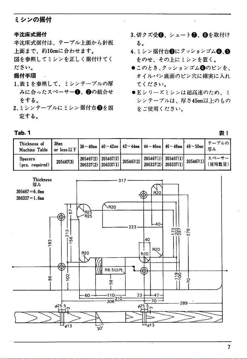
Semi-submerged
Install
Needle Plate is
above
INSTALLATION
machinesothat
from
Table
top.
Installation
the
top
approximately
See
the
illustration.
surface
10cm
of
1. Use Spacers O 0 between Machine
Table
and
Rest
Board
as
shown
Table
1.
2. Fix Rest Board 0 rigidly under
Machine
Note:
The
thin
Table.
table
tableofthe
may
thicknessof45mmormoreisrecommended
cause
excess
vibration/noise
3. Set
Waste
Chutes O O and O as
shown.
4. Put Cushion Rubbers O and 0 on
in
©,
making sure the holes of Oil
Reservoir fit
Rest Board 0
Rubbers
during
O-
sewing.
Set
Machine on Board
the
pins of Cushion
for
E52.
Using a
Needle
plate
top
surface
CQ
Machine
T —
table
Machine
T—7';u
•
table
Machine
Cushion
rubber
rest
board
Page 9
±MtX\
mOmiZ^h-^tto
m^^mix
mi^^m
1.^l^#ML-C,
2.i'>yT-yjuiz
^tl>o
Tab.l
Thickness
Machine
Spacers
(pcs. required)
of
Table
Thickness
i
i^y^iEi
38mra
or
=
x>T-7';uc7)Jf
= y
less
JUT
205467(3)
<
O.
38~40mm
205467(2)
206337(2)
jgjtitT
©<7)|a'^^i-
40~-42inn 42~44inm
205467(2)
206337(1)
3.-W^x^O^
y^-YO.
©^JOi#{t
ho
4. $
v>^g#ia®lc:J'vx3
<
•
Z(7)t
14
•
E-y')-X=
yyr-y'Jia^
205467(2)
^<x>±.i,z i y y
^ ^ y y 3 y
44~46inm
205467(1)
206337(2)
t°
yynm^Mxifztb.
Jf^$45mmJU±<^ t
46 —48mm
205467(1)
206337(1)
>3i'aO>©
xj^Qcotr>
>/^{cMillie
48~50mni
205467(1)
f-7;K7)
(o
^,
AfL
i
205467=6.
206337=1.6miii
Omm
-40-
R6.51UR
I
Page 10
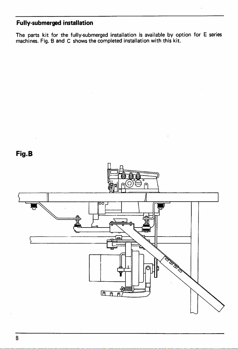
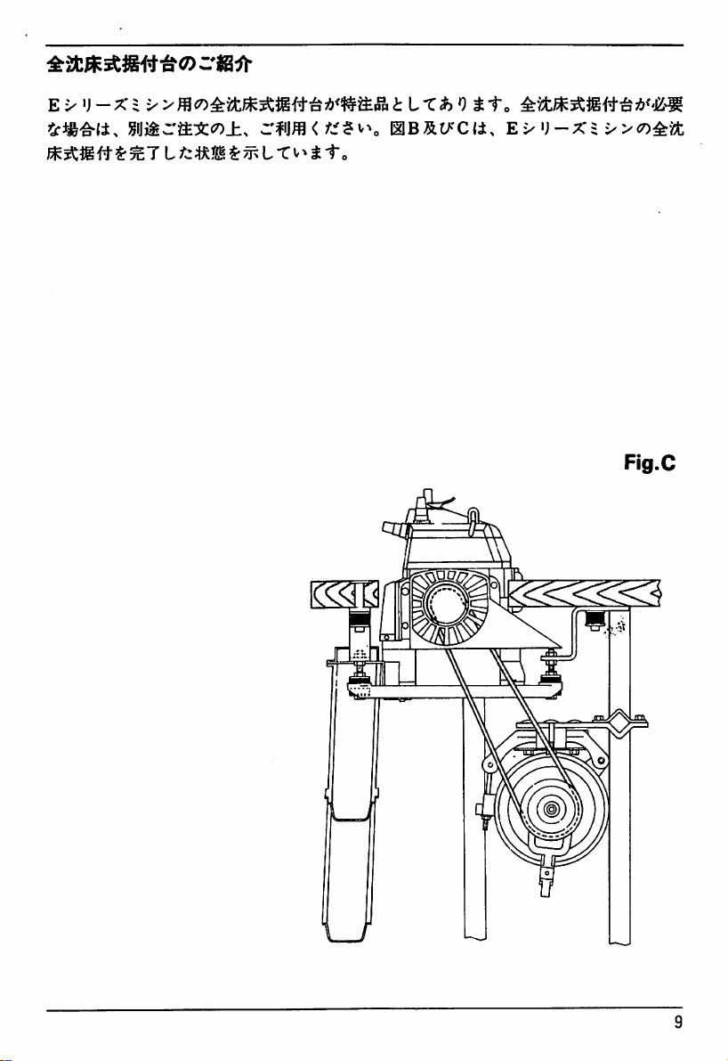
Fully-submerged
The parts kit for the fully-submerged Installation is available by option for E series
machines. Fig. B
Installation
and
C shows
the
completed installation with this kit.
Flg.B
m
Page 11
E X u
-X
= X
«imra:fi:«7)_h^
>tLx^ntto
LL
TV>J
^'itm^miit^<'m
niBSt/cii,
to
e->
^)-xi
><7)^m
Fig.C
Page 12
DRIVING
BELTING
Each
machine
beltofthe
1.
Clutch
than
2. Belt: V
3.
Motor
motor:3phase,2pole,
4CX)
belt.
pulley: as
Machine Pulley
Motor
measuredatits
MOTOR
should
PULLEY
useamotor
following specifications:
watts(1/2HP).
Type
M.
showninTable
Diameteris55mm.
Pulley
Diameter
outer
should
diameter.
AND
more
2.
and
be
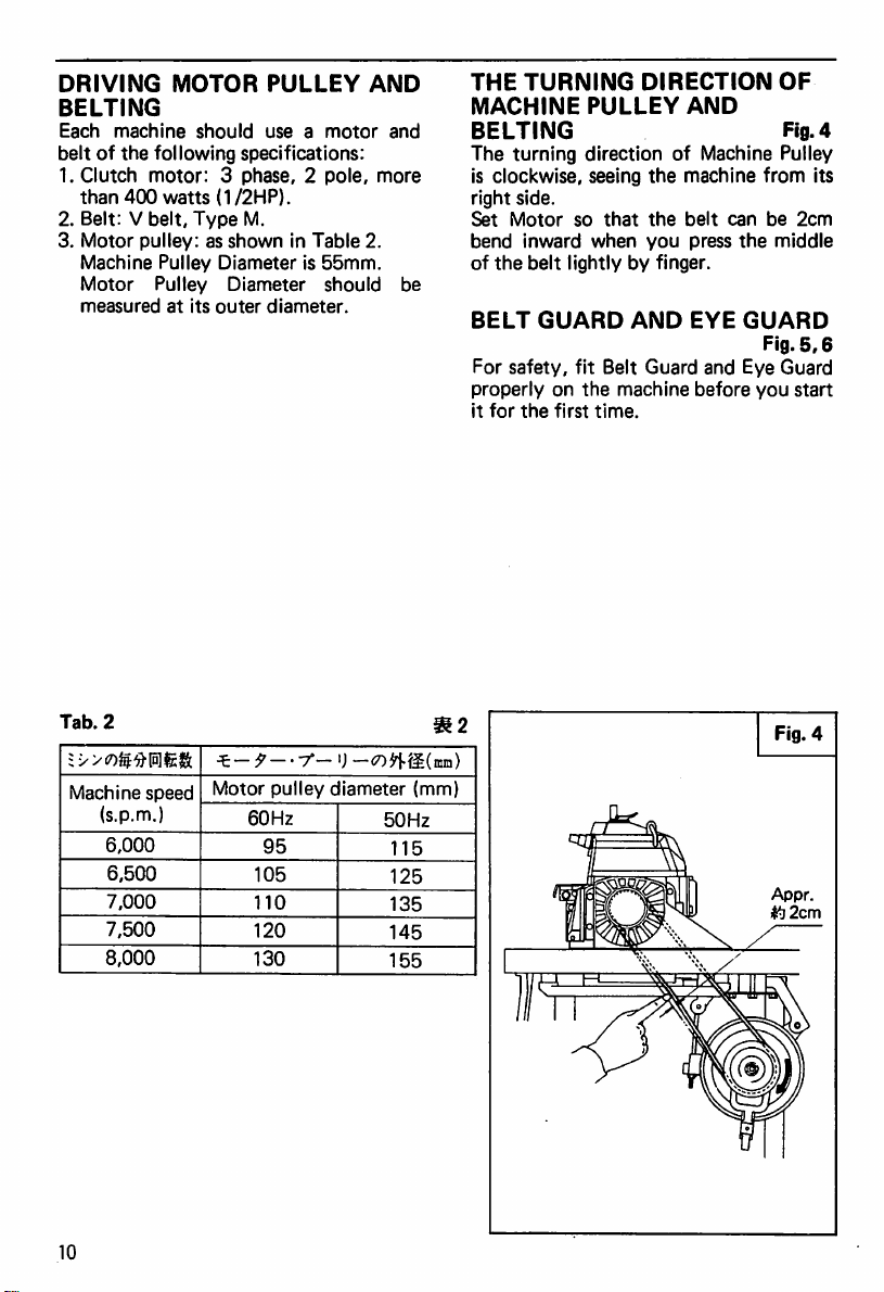
THE
TURNING
MACHINE
BELTING
DIRECTION
PULLEY
OF
AND
Fig. 4
The turning direction of Machine Pulley
is clockwise, seeing
the
machine from its
right side.
Set
Motor
so
that
the
belt
can
be
2cm
bend
inward
of
the
BELT
For
safety,
properlyonthe
it
for
the
when
you
AND
press
EYE
belt
lightly by finger.
GUARD
fit Belt Guard and Eye Guard
first
machine
time.
before
the
middle
GUARD
Fig.
you
5,6
start
Tab.
Machine
10
2
(s.p.m.)
6,000
6,500
7,000
7,500
8,000
speed
•i—
f — ' U —
Motor
60Hz
95
105
110
120
130
pulley
diameter
50Hz
115
125
135
145
155
m2
(mm)
Fig. 4
Appr.
Page 13

'<;uhU,
^-li,
M®V-<;uh
=v>[a]K|{[t.
(ns)
2®400W[^ii^y-v^
?rrl£ffl<
rmcr>^<r>m
^
v><7)ii]fe:^ifiii:'^;u
:
x>t7)EIfe:^rnlli,
-r,
^[aort.
h(7)5SiM^/;
([S]4)
7°-'j-fi|ii^'.^M
• = 55inmT"-r,
• •
y-u-[±,
TEct)^
h
'<;uh?:7/<-^t/'T'f
K(I2I5.6)
Tir-K(±,
?y-
K^IEL<Jf2
f^ScT)
BK
Page 14

LUBRICATION
The
oil
was
drained
out
from
the
machine
when shipped. Fill Oil Reservoir with
factory supplied oil or equivalent before
operating. Use recommended
only.
Keep
the
enough
the
machine;
Indicator
two
lines
Window
should
'h'
O.
the
and
Change oil entirely at
from starting. After
every
half
a year.
Lubricating oil
Use Mobil Velocite Oil No.
equivalent.
amountofoil in
head
be always
'1'onOil Level Sight
the
that,
10
type
oil
of
Oil Level
between
the
end of 4 weeks
change oil
(ISO VG22) or
To
fill
oil:
1. Take
into
Oil Reservoir
until
reaches
out
Screw O and pour fresh oil
the
headofOil
the
upper line
Sight Window O
2. Re-place Screw O
To
drain
oil:
1.
Remove
and
2. Screwout
3. Re-place Plug
the
machine
setitonatable.
Drain
©.
(QOOc.c.
Level
'h'
from
Plug
O and drain oil.
Fig.7
capacity)
Indicator
of Oil Level
Fig.8
its
stand
Fig. 7
O30kg-cm
12
Page 15

>'W'NalO(ISO
VG22)ttz\t^iXtW\^<nh<7^^ii\t^^
^
;ur-
X0c7)_h(7)|^
^
*'•*0
^|±
I:i6-C7&^
h t
b 1 ^ ^
T'xn-c<tl
t,^C7)
;4<7)^a^a(I217)
3}-^
>'i.r-x0c7)ig^>^h
<7)±PHtTiS^^L-Cv^^to
±.<^mh
^(7)|g^-C'U
</'j:'$v^
e(ci5o'v^ri'/ji#(±,
-c,
900cjc.co?|}i7!)^'(j:v>
yur-->'<7)2^<7)i^6orf,i(c
t«li.
J: ')
^<
t
t'i^T
t) S 1"o
-f-Slc^l-^L
>i>
A
^?6<7)LA^/cda
f-7';wcoftHtn3&»b
t ^
fi-o
PMm<^
8)
= >
i/©^(i-r
L-Ct
Fig. 8
13
Page 16

Oil
filter
Fig. 9
Filter O should be kept clean. Lubrication
oilisfiltered
and
deliveredtoall
frictional
surfaces. Cloggingofthis filter may cause
lackoflubrication
of
parts.
Check and clean Filter O when:
amountisproper
not
change into green when starting
machine,
or
the
the
oil
jetisweak.
1. Remove Screws o and Cap
2.
Take
out
or
replaceitwithanew
3. Re-place Cap 0 and Screws
and
accidental
but
Oil
oil is
dirtyorcontains
FilterO.Check
Monitor
O.
and
one.
seizure
the
clean it,
0.
oil
does
the
foam,
SILICONEOILFORH.R.
DEVICE
Fill
the
Reservoir
for
H.R.
Device
Fig. 10
with
factory supplied Siliconeoil or equivalent.
The oiler containing 50c.c. Silicone oil is
supplied
Silicone
To
fill
with
oil
the
the
for
machine
Reservoir:
machine. Never use
parts
lubrication.
Open Cap O and pour silicone oil from
here.
Specificationofthe
Kinematic
Viscosity
(centistokes)
Viscosity
100®F
37.8®C
210°F
98.9® C
Index
recommended
Brand
19.0 14.6
4.0
124
//X
"A"
type
oil
Brand
"B"
3.6
143
©
&
30kg-cm
Page 17

7 ^
i X > S
f^titzmiiy
b-f,
tt.
= X
^ ^ ^ I^|2^ L
:k<r>J:')^j::^m<r>t^U.
(I,
:t^
^feA'{croTv>^o
'£«-f
^tT-o
X <
cr>.mtfzimm^ix<fz^\'\
1.±^->
X©^•),
(J;
> 7 ^
Sto
^
»)
m'x^x^-ho
7^
;u:?-co.^.^^
^©IrH't'o
)V9
jA^
z'^M
^^7)
n,
—
z
2.7
^
3.7^
;u^-0^^ii')
HR^Mffl
:> 'j •
>>6
(010)
E52lf^iOxI)^lymii^F-myHRXm
M) $r
t57&^'=
-^ylzitMt
HR|SI®(7)$&>4(01O)
xij=j>:J'>7
ifX$^'/^lX<
(#m;8cc)
fz'^v^o
LXif^^X^^ti'o
50cx.A^
coMO^I
Fig.
10
Page 18

NEEDLES
The
type
of
the
Organ
other
DCx27,
similar
factory-set needle is
Machines can also use
needles
to
DC x
27.
This,
however, may require re-adjustments of
Loopers and Needle Guards.
REPLACING
1. Loosen Screw O and
needle.
2.
Insertanew
holeasfar
NEEDLES
needle
as it will go.
into
Fig.
remove
the
11,12
needle
3. Tighten Screw O after making sure
long groove on
you.
Note:
When
loosening
be carefultouse Allen Wrench
Thisisto
avoid
the
needle is facing
or tightening
the
screw
holeofScrew
Screw
properly.
O from damaged.
old
the
O,
Fig. 11
16
Page 19

;U7:?'>DCX274f^'«Li1-o
•f-S) 2
<!:
IT'#
^i"o
i 7'^) i > > cr)1fli\\1j\"]iz\n]
ItT,
iEL<irz')f^-ltX</^'$v>,
0t.il:T>^'O^I'iJ
i>t^li.
"7
» t° > U >
t'<
^nhfz^).$i15-ftlt
"f"^A^^'/v{-7U.^(-j'i'jAA
tz •) t
A ^ il't ^ 4- V>J:
1
bkg-cm
1. Jt.ll:
1
i-'O^
bkg-cm
I-J)
-i)
i^Jt
-2>
o
Fig.
12
17
Page 20

Fig.
THREADING
Thread
your
machine
correctlyasshown
13,14,15
in Fig. 13, 14, 15. Incorrect threading
may
cause
thread
or
uneven
stitch
breakage, skip
formation.
Ja.l-.coJ-iifMi.
Pass
Also,
the
'A'
pass
stitch
3'j
when
'A'
length
stitches,
stretch
when
longer
REGULATING
THREAD
TENSION
Changes of threads, seam width, stitch
length, etc, require re-adjustment of
thread
tension.
Adjust individual
follows:
To
increase
Turn
To
decrease
Turn
. A ^JiL T < t s
threads
than
are
threads
2.8mm.
non-stretch
used.
tension:
Nut
clockwise.
tension:
Nut
counter-clockwise.
are
used
thread
with
Fig.
13,14,15
tension as
Fig.
13
18
Stitch
type
503
503
Page 21

^<7)3iL3&\/i(Ell3,14.I5)
tt/.
'),
li±oy:;55i.rHC7),aii'tui»!^^i?Li
to
{ciEL<iifiL'C<
s^t-t
zcni^^Y.
X.
t
ilii'
v
h-ei»Li:
(013,14.15)
<
•>3>f}<i^h'M<
J: ilCiDJ
a S
to
Fig.
14
Stitch
type
504
504,505
and
505
Page 22

PRESSER
Presser
possible,
fabric and
foot
FOOT
pressure
while
obtain
PRESSURE
shouldbeas light as
still
sufficient
proper
stitch
Fig.
16
to
feed
formation.
Thumb Screw O regulates the pressure of
Presser
Foot.
Turn nut O clockwisefor more pressure,
and
turn
it
pressure.
counter-clockwise
for
less
STITCH
LENGTH
ADJUSTMENT
Fig. 17
1. While pressing Push
Button
turn
Handwheel until Button 9 drops in.
2.
Turn
Handwheel
stitch length. Release Button
Table- 3
the
of Main
The
setting
shows
pulley
scale
Feed
relationship
and
the
ingtosuch
differential
further
the
relationship
setting
and
Dog. See page
between
stitch
sewing
feed
length
conditions
ratio,
foradesired
#.
the
movement
22.
the
pulley
varies
as fabric,
etc.
Therefore,
between
scale
accord
re-adjustthe stitch length when the sewing
conditions
have
been
changed.
Fig.
15
20
Stitch
\m^
type
512
512,514
and
514
Page 23

comma.
L1$@/im•riGi'fl
*'''0
mu-B:^0mmm\7)
mm^m
l.Xv
->
-r—
ij — ^
RELATIONSHIP
SETTING
FEED
Tab.
Max.
ratio
i^±mit
1 ; 2
1:3
1 :
1 : 4
DOG
3
diff.
1.3
>0^n<
lai-o-ry iy i
zwmi\x>m^m$x-ro
AND
Type
machine
Seaming
Shirring
Serging
Special
BETWEEN
THE
i y
of
9 \ X
X-y>r
lej L
PULLEY
MOVEMENT
><0
1
1mm
0.7mm
1.6mm
0.6mm
Fig.
-r
OF
1.5mm
1mm
2.3mm
0.9mm
16
2.x
• -^-3
•
SCALE
MAIN
Pulley scale
2 3
2mm
1.4mm
3.1mm
1.2mm
^
-7"-u-^iu)L-r.
(±,
kkkmi}i:t{2zam^yw^^
i
;Ei§
U \iijco7£>M w; t
4j^t!lc7)MM^.
mi'\^comta
MS
i i!^ @i:i ^ i:
Miffl
^n-(^'Sci\:a
i5i}^L-C<A:'V
x—
4
2.5mm
1.7mm
3.9mm
1.5mm
>0^
—C^ L
c7)|}y^>j<
yW}}(0^-a/)XzKi:
J: o
-c.
comma
'Scit
tt
b
V,
'J —
Fi
5
3mm
2mm
4.7mm
1.8mm
6 7
3.5mm
2.3mm
5.4mm
2.1mm
-r-
tl
mtsmu
M ^
JA/u
L X
t\
'j - H
L ^-ro
com
^3
3.8mm
2.5mm
5.9mm
-
Fig.
17
21
Page 24

ADJUSTING
FEED
The
of
menttothe
RATIO
differential
the
amountofMain Feed Dog's move
Dog's movement. When
Main Feed Dog's movement is bigger than
that
of
ment,
the
In reverse,
Adjust
the
to
the
fabrics
1. Open Cloth Plate.
2.
Turn
Screw 0 clockwise if necessary
to
stretch
Turn
necessarytoshrink
DIFFERENTIAL
Fig.
feed
ratio
means
amountofDifferential
Machine
diff.
feed
th^
ratio
Differential Feed
fabric is
the
stretched
fabricisshrinked.
18,19
the
ratio
Feed
amount of
Dog's
move
in stitching.
differential feed ratio according
and
the
operation.
Loosen
more.
Nut
O.
Screw 0 counter-clockwise if
more.
3. Tighten Nut O after adjustment. Shut
Cloth
Plate.
Note: 1. Generally,
ferential
for
convenient
the
adjustable
ratiointhe
2.
The
1 : 3
shrink
the
3.Inthe
when
ratio
0 is
Plate
1 : 2
is
the
set
O.
Setting Lever 0 upper than
the
scale2makes
stretched;
1 :
0.7.
4. Table 4 shows
of
the
and
the
0
the
maximum dif
feed
ratio
to
range
machine.
ratio
fabric
much.
ratio
approximately
top
surfaceofLever
on
the
adjustable
the
differential
set
positionofLever
is
represent
of
machine
machine,
scale 2 of
the
fabric
up to
relationship
feed
used
the
can
the
1 : 1
ratio
Tab.
4
1.6
1
1 :
1
3
:0.9
:2.3
1.4
4
1
:1.1
1
:1.7
1
:2.5
1
:2.8
1 :
1:2
1
1
5
:3
:3.3
1.3
6
-
-
-
1
:4
Lever
setting
on
the
scale
1
:1.3
1
:2
1
:3
m
1
:4
22
1 2
-
1
:0.7
1 : 1 1
1 :
1.1
1
;0.7
1
:1
:1.51:2
1 :
Page 25

^i!il:b<7)iSg5(iiii8.i9)
mbit
L,
1.
2.imry-^
^ <
Kx^)
tli.
n,VM(^r.mzIt
7.7°U-
o
4-,
itc
'i m t
'J U ^ (t ^ ,
b -h
hiz
01-1
t.
myjm}j}t
vhO^l'JJ
loittmutij-k
(y^kkkmbit^Wiltt.
•
^:#J:tl
^ <
• 1 :
lt^<
mm
• mm^^t t ®c7)-t:
<
Misuse
1 :
^^^
k4
:
3<7)=x>(i,
2<r)i->>li.
H
lizK^ntt.
X'.k(--b••>'
').
iti-:A:(i 1 :
l3I.Ii')^A-
^1-0
,j)i]fi|ju^<-
'iiS2<y){mx\
z(r>mitX
h 1" ^
0.7-C't„
••/}•fii/M?i:t<7)m]
xiTo
mm
')
Fig.
18
Fig.
19
23
Page 26

REGULATING
1.Turn
Handwheel until
lowest.
2. Loosen Screw
Holder 0
tighten
Screw
3. Loosen Screw 0
Knife Clamp O to
untiladesired
Tighten Screw
4.
Turn
Handwheelsothat
of
Knife
to
is
SEAM
O,
WIDTH
Upper
push Lower Knife
the
left and lightly
O
and
the
seam
widthisobtained.
©.
0-1.0mm
move Upper
right or left
the
above
Needle Plate top. Loosen Screw
then
Holder 0 will return to position.
5.
Make
sure
alignment. Tighten Screw
Knives
6.
Check
Knives
of
thread
wheel and
Note:
Needle
widths
are
proper
width
between
check
are
obtained
size Needle Plate for
required.
cut
Plates
are
in a
O-
sharply;
the
available.
insertapiece
Knives,
cuttingofKnives.
for
various
with
use
Fig.
turn
Best
20,
Knife is
point
from
perfect
Hand-
seam
results
of
seam
O.
the
21
'a'
CHANGING
1. Loosen Screw
Holder 0 to
tighten
Screw
UPPER
O,
the
O.
KNIFE
Fig.
20,
21,22
push Lower Knife
left and lightly
2. Remove Screw © and Upper Knife.
3. Tentatively set new Upper Knife with
Screw
©.
4.
Turn
Handwheel until
Upper
Knife
Lever © is lowest.
Move Upper Knife up or down and
adjust the overlap to 0.5-1.0mm.
Tighten Screw
5.
Turn
Handwheel so
Knifeis0-1.0mm
Plate
top.
Loosen Screw
returntoposition.
6.
Make
sure
alignment.
Tighten Screw
7.
Check
of
thread
Handwheel
Knives.
Knives
©.
that
above
O,
then Holder 0 will
Knives
are
O.
cut
sharp;
between
and
check
the
point
from
in a
insert
Knives,
the
'a'
Needle
perfect
a piece
turn
cutting
of
of
O
25kg-cm
©^25kg-cm
©30kg-cm
Fig.
20
Page 27

rtl
<7)1^15
(020,21)
(020,21,22)
4.-7°—'J—•SrHlLT,
y
XOa.^.Tb'i^^mS-LiaS-C,
mnitc
5.^<^^f±tlX'_t^
ti^tfzZ
6.
/
• /
iz^.^xtl.
XA-Xlc-Ijon-S)^
? *'^o
•
E52ff^{3{i,
t
-r-')
7&»;1>>'')
y^»_.y;^^^»)^-^^
—y
t^C.ikLX
21E160
X
iT/
X7b<h° y ')
±T^xc7Df{U
-^HI
i < fZ
rl^(-E£;b/,;^->''
< A:*$
J:-3
ic,
0-1.0
Jh^-^x
L
T,
rt]^:A:rtiu
Fig. 21
_h
MiiZ'^-\t^
2.
il".^•>
3.rrL«'^ii/
il:46i--&„
4.r-')-^|u]L-r,
i
T'$
(t\
J: J
0.5•—1.
5.r-')-^||i|L-C.
y
COa.'1:/}^
mraU-n-io-ti:X» ih
6.^<^-i±ijX'
\-.y
t^LtzZt^m-h^shXt^^.
7.
/
Upper
knife
yy
X
XO$rfliilJii't"-I)o
') ,
[•./
i\A^i^0X'ifi
li/
Jr. y :^
<!:
T y X 7:?«'22[aco
0mm;!;'
^ 3Ij/JiJrifti
rtJfAiS
21|5]<7)J: 9
^X\
J"-*
xO^'^1'
t y y XT^^'h' y 9 j
1- _h y
0-1.0
•5>
ih=f^x
Fig.
ii
o
22
O^
1.0mm
I///////////A
0.5~1.0mm
Lower
yyy.
Needle
top
surface
W±ffi
knife
plate
25
Page 28

CHANGING
1. Loosen Screw
Holder
tighten
2. Loosen
0
Screw
Screw
LOWER
O,
push Lower Knife
to
the
left,
O.
0
for
KNIFE
Fig.
23,
and
Lower
Clamp O and removeold Knife,
3. Insert new knife under Clamp
O.
Move Knife up or down until its
cutting edge is level with Needle Plate
top.
Tighten
4.
Turn
See Fig.
25.
Screw
©.
Handwheel so
that
the
point
of Upper Knife is 0-1.0mm above from
Needle
Plate
top.
Loosen ScrewO,then Holder 0 will
returntoposition.
5.
Make
sure
alignment.
Tighten Screw
6.
Check
Knives
of
thread
Handwheel
Knives.
Knives
and
are
in a
O.
cut
sharp; insert a piece
between
check
Knives,
the
cutting
24, 25
lightly
Knife
'a'
perfect
turn
KNIVES
Knives
must be kept sharp. Lower Knife
may be sharpened by use of a grinder
while making sure that the correct angle
is
maintainedasshown
in Fig.
Upper Knife may be sent to our distribu
torsorreturntous
it requires special grinding.
of
for
resharpening since
Fig. 26
26.
25kg-cm
@ O
m
©30kg-cm
Fig.
23
0 ~
1.0mm
I/////////1
Fig.
24
Page 29

(11123.24.25}
1. jI: XO ^ '
U , jh VO ?r
2.j|-.t^i7©^
S.rrL^^Tz'
1-1)^36,
:?.^Tz'
iO^^I!ilt-"^:3A.^.
7.
^l-.ifti
4.7-';-^LolLt.
y 7.
<7)a.'.'.(7!;>
mmd ,
5.z<;M±:^j
t^xLtiZb^
6. /
r-.l:
7.mi^mi3^shho
"5)
3^, T z' 7.
ffciUliiri,„
TV7.^H1-o
7.fj0>Ty
25|}<l£7)J;
i Inj t
24|7|c7)J: T
[-.i/ii
ll".
t'«
i70^
^ 7. > >' / 7.
X . Jh V
frO
tX\
^ u
tUTz'
?.Vi$(-
I'J)
.2)
t:
{-,
0-1.0
^ j
••/
:7 ij
Fig.
x#
.1:
25
T',
UWlllllW^'i/Lt'C:-^-?!;^'^'}
^ c7)|ll]u /
li,
ATz^
Tz^
7.^fi}f^'i(i:LT
7.^{|fi'i(i:ti:
7.c7)yjap^^ht;
mv ^>Jvt^ i: L i
LT,
jI-:{irii(cW«.^T'<
A I-.7
7.^^i}f^'I(l;i-4i^^^i.
^
f1=m'f-^.|-.lt'^
7)J-.z^7. ^
L
^!iikfhJ-fik-|r(?
h6z
t =^io0jib>L
87'
\
/ThG;
L -CI ^ /-i ^ . W iti
^(i,
Lito
tzihii
it.
62'
<
to
26[a^#Hn
h , 'w-(c^jj|ij
Fig.
\
26
Upper
knife
1:7
7.
0.5~1.0mm
Lower
T7
Needle
top
surface
I'l-f/jt.l-.ifii
knife
7.
plate
201127
J5'
202295
27
Page 30

CHAINING
THREAD
It is necessarytohave a chaining thread
approximately
10mm
long behind
the
presser foot when starting to sew.This will
avoid
"skip-stitches".
After
replacing needles or
thatacontinuous,
thread
comes
out
foot.
HOW
TO
CLEAN
MACHINE
Cleaning
important
to
foot
out
lint
and
loose
covers and
position.
the
operation.
remove
the
any
and
swingitouttothe
covers
from
under
lint
and
around
the
or
return
machine
needle
use a
smooth
from
parts.
remove
the
under
YOUR
is a
It is
Merely
loopers,
plate.
lint
foot
thread,
neat
not
all
the
Blow
brush.
to
chaining
the
presser
simple
necessary
release
left.
collected
feed
out
Re-place
the
sewing
check
but
the
Swing
slots,
any
DAILY
Before
*
Check
MAINTENANCE
morning
oil level is
start
correctly
maintained
in Oil Level Sight Window.
*
Check
needleiscorrectly
set
and
not
damaged.
*
Check
threadingiscorrect.
*
Check
chaining
10mm
threadofapproximately
long
remains
behind
presser
foot. ^
* Manually lubricate the oil hole for
Needle Holder Guide Stud before
morning
After
* Remove
start.
closeofwork
dust
and lint deposited in
the
machine specially around needle plate
and
looper.
* If any trouble or irregularity is found,
report it to the plant mechanic for
adjustment or repair.
* Keep record showing number of needle
and
thread
breakageaday.
* Dust cover, furnished with machine,
should be placed on
the
machine.
28
Page 31

< /:;'?v>o
it«7)^#;t0#{3{i,
'£'-r
LT
^A;/l$
<
;i^T@v^-Cv-»;Mli\
ixXiv^
ixXi,
?
^"*0
JNpIc.
ItIR,
^iiv>(z^l^LT
</Jf
n'§:<7)
"C
V">^i"T&'o
• »).
• :S$
lOmm
<-b
L t
ro/ci
• a
>60111^^
•
tmiX^^^
? v>„
%^mntifz»),
ttz^
ItliiEL
V^60^I^3i>>'T-TV^^
Lfz-h
L-C
<
m^%it
mA.
15&»
/Jf
29
Page 32

it^iii';o
±y
x^<Tfc,^.cot^.
T:^[^(7)^^$:[gl
m'ik-n^lkx/l.
1COJ: 9
'e
SiSff^^C
i1"o
i^aji^^504
T(©ffllJ)C^
tzf:fL.
')
#{t
j:
• 512 •
ff-C^»)
#1-^.
tzm^it
aS7&^'A7{C^»)
liB?^^503
ffiij)
{c^{f-c^»)#tti:<
m)
fl-:^ji0-®{i.
^tto
«505<7)ii'^(ix
-c^')
SHajli-g-lis
#lt
;u—rbo
.i'>y
tto
©:^[B]{c^-y:^
T <
x>mmz
S:i±
©lic:^
x-ox.
(©
•)
20mm
039mm
a :15~
48.5mm
16mm
qT^
30
Page 33

(02)
J: ') . 'j
T'<7)^^a
Itt
^15-16inin{Z'^b-yrT^«){t
<
(7)±mt
tto
iiiJI^5^504
«505 «514(7)J®'g'. 2it>'503
<fX\
8mmJU±<7)
lia}^^512•503(^|g5UixSa'503<7)if
>
^'X\
mU^
^*"'2.
t±.
C{cflx»)#lt-C<
»)Sto
il®c7)@7^41.1:,j:0,
±®i
•C<7)-4^ b
©S}^^503
6~7min{;'^h-li-t
liaJK^512a)ii^ttslO~llmni{C>^h-ti-
eaJK^504
E{c^
H S
JK^503(7)ia-^(i
^ ^ O
• 504 • 505 •
• 505 • 512 • 514<Z)«-g-(i,
t)ftlt-C
</•::'$
ab
<
').
XD (::
5t4(7>ii-g'».
2
niiD©:^[fi]
fi»)
fttt
X <
A(c
>0:^(6]
{c
i:^to
31
Page 34

NEEDLE
Standard
parts
is as
correctly
Needle
Check
dimensions
is
lowest.
THREAD
settingofthe
showninTable2.Set
dependingonthe
thread
takeup
O
'a'
and
Needle
control
Needle
takeup
Needle
guide (left)
Needle
guide
Needle
guide (right)
needle
'b'
CONTROL
Fig.
1.Tab.2
thread
stitch
types.
when
Upper
thread
parts
thread
thread
thread
(center)
thread
control
each
Knife
Symbol
in Fig. 1
o
0
0
o
part
a
b
503
20mm
48.5mm
highest
©
highest
0
20mm
48.5mm
lowest
lowest
At
504
the
a :
20mm
Stitch
20mm
48.5mm
©
0
centerofthe
b :
48.5mm
type
505
highest
0
highest
0
©♦
512
20mm 20mm
48.5mm
lowest
©
lowest
©
long
groove.
Fig. 1
Tab.
514
48.5mm
lowest
©
lowest
©
2.
Needle
thread
guide
(left) Q
and
(center)
0
Only
when
the
both
needle
and
typeis504,
512or514
set Guide 0 0
polyester
looper
threads
threads
for
sewing
highest
(on the © side). If
and
are
light
used
the
fabrics,
for
stitch
Guides 0 0 are set lowest (on the 0 side)
in
this
case,
uneven
stitches
speed
32
varies.
occurasthe
machine
Move
Guide 0 0 in the 0 direction for a
tight needle thread in the seam, and in the 0
direction
foraloose
needle
thread.
Page 35

LOOPER
THREAD
CONTROL
Fig.2Tab.
Standard
parts
correctly
Upper
Check
right
settingofthe
Is as
shownInTable3.Set
dependingonthe
looper
distance
dead
thread
'c'
point.
when
looper
stitch
takeup
Lower
thread
control
each
types.
@
looperIson
Upper looper thread guide O
• When required stitch length on
operation
with
the
stitch
than 2.8mm, set Guide O to C.
•
Also,
set
Guide
O to Cforthe
operation
• In
with
the
caseofstretch
the
stitch
type
threads
type
503isshorter
blind
503.
the
serging
hemming
like
wooly
threads,set Guide O to A for any stitch type.
thread
Lower looper
In
the
case of
stretch
guide 0
threads
like
wooly
threads,
setGuide0 to Dforanystitchtype.
part
the
Lower looper thread takeupO
• Check
3
• Only when the wooly threads (type G) are
Move
direction for more threads in the seam, and in
the © direction for lessthreads in the seam.
distance'd'
the
right
dead
used as'
the
seam requires
in it. set
approximately
Takeup
Takeup
when Lower Looper is on
point.
lower
looper
more
lower
O In the 0
2mm
than
standard.
O and
Guides
039mm
c :
15—
16mm
thread
looper
O0
and
thread
direction
in the ©
the
by
Looper
control
Upper
thread
Lower
thread
Upper
thread
Lower
thread
thread
parts
looper
takeup
looper
takeup
looper
guide
looper
guide
Symbol
In Fig. 2
0
0
0
c
15—16mm
d 6
503
—7mm
B
0 D E
15—
6 —
504
16mm
7mm
B
Stitch
15—
6
—7mm
505
B
E
type
16mm
512
15—16mm
10—
11mm
C
E
15—
6 —
Tab.
514
3
16mm
7mm
B
E
33
Page 36

AppliedtoE52
of the
machine
number #7605897 and after.
STANDARD DIMENSIONS ON ADJUSTMENTS
(Dtt<7)S?
t
^j:')
10.8~11.0mm'
mi-tm
Standard
7. ^ >
r—
lift
[•'')
High lift a =
ij -7
1-
Needle
height
From
the
point
top
surfaceofNeedle
is
highest.
t ,
-i:$f-coi:iKlil]o24^^i-
^0~0.05mm
of Needle
;u—'<•
a=
9.9~10.1mm
y h
10.8~11.0mm
(Note
Plate,
1) to
when
the
Needle
Standard
x^>r-V')y
High lift
ys^iIJ7 h
Lower
From
the
of
Needle
extremely
lift
b=
looper
Looper
left.
b=
3.8—4.0mm
[•
3.6—3.8mm
setting
No.
pointtothe
iNoteD,
1
when
centerline
Looper
Is
Lower
No.
Clearance
Looper
when
the
34
looper
2
Looperisopposite
centerlineofNeedle.
Note1)The
and
setting
between
Needle,
left
Needleincaseof2-needle
machines.
Page 37

^>j;ol-r
<
(5);i/-/<-;
A.
B-t^
Loopets'
Clearances
Lower
cross.
0.2mm
clearances
between
Loopers,
Upper
when
t^<r)
0.5mm
"v
Needle guard (rear)
From
and
when
they
Looperisopposite
lineofNeedle
T
/u—7b<lt4'.C.-c7)t^.
Needle
the
setting
GuardtoNeedle,
point
of
the
(Note
1).
(9)}fxS'J»
Xt
Lower
center-
^J:')
(Z)tti:8tS(89)a)Ktra
0.1~0.2mm
Needle
guard
and
(front)
between
Needle,
No
clearance
Guard
dleislowest.
setting
when
t X
Needle
Nee
Feed
From
tooth
to
Plate,
the
1.0mm
dog
height
the
top
of
Main
top
surfaceofNeedle
when
Feeds
of
Feed
are
the
highest.
back
Dog
Standard
liftxrJ'>f—K')7
High lift
E52-210,
Presser
From
surfaceofNeedle
foot
the
210C,-211
lift
bottom
-'^^Uvh
surfaceofPresser
Plate,
when
Footislifted
h c =
c =
c =
Foottothe
5.0mm
5.5mm
5.5mm
top
up.
35
Page 38

CO
0
0
CO
1
1
1
CO
to
CO
to
ai
to'
ADJUSTING
LOWER
UPPER
Set
your
machine correctly as specified in Tattle.
36
NEEDLE
LOOPER
LOOPER
HEIGHT
SETTING
SETTING
Machine
type
E52-130
210
210C
211
220
221
231
242
243
131
132
133
134
135
136
137
140
Needle
height
9.9-10.1
10.8-11.0
9.9-10.1
••
" "
10.TB-
9.9-
" "
10.8-11.0
9.9-10.1
••
" "
" "
10.8-
9.9-10.1
••
10.8-11.0
11.0
10.1
11.0
Lower
looper
setting
3.8-4.0
3.6-3.8
3.8-4.0
••
3.6-3.8
3.6-3.8
3.8-4.0
..
3.6-3.8
Upper
l(X)per
setting
4.5-5.0
5.5-5.8
5.3-5.8
"
4.5-5.0
5.5-5.8
4.5-5.0
5.3-5.8
5.5-5.8
4.5-5.0
5.5-5.8
Page 39

i
>->(1980#
m m
i
E52-130
131
132
H- §
9.9-10.1
10.8-11.0
9.9-10.1
133
134
135
10.8-11.0
136
9.9-10.1
137
140
10.8-11.0
210
9.9-10.1
210C
211
220
221
231
242
243
II
II
10.8-11.0
9.9-10.1
II
10.8-11.0
~f
3.8-4.0
3.6-3.8
3.8-4.0
II
II
3.6-3.8
3.8-4.0
II
3.6-3.8
3.8-4.0
II
3.6-3.8
3.8-4.0
3.6-3.8
—
aifi
4.5-5.0
5.5-5.8
II
II
II
II
II
II
II
5.3-5.8
II
4.5-5.0
5.5-5.8
4.5-5.0
5.3-5.8
5.5-5.8
4.5-5.0
II
II
II
II
II
II
5.5-5.8
37
Page 40

I
PEGASUS
SEWING
Ca,
LTDf
MACHINE
MFG.
4440
 Loading...