

Page 1

PEGASUS
INSTRUCTION
FOR
MODEL
DCP-101
DCP-101W
HIGH
COMPLETELY
LUBRICATION
DIFFERENTIAL
SPEED
AUTOMATIC
FE|^„„„^^
DCP>t03
OVERLOOK^
STITCH
rTr
MACHINES
jCP
NO.
p
a
.
d
^
r.p
DCP-105
OATEf"^.
'
*'
DCP-109
F>
OBOEB
MIMA
SEWING
OSAKA
MACHINE
TOKYO
JAPAN
CO.,
Model
LTD
DCP-101
Page 2
ORGANIZATION
CHART:
DCP-101W
DCP-103
DCP-105
DCP-109
FEATURES:
4,500
stitches
Completely
Differential
Totally
enclosed
Independent
Single
main
Simplified
Uniform
Effortless,
(Suge?
1
per
minute
automatic
feeding
mechanism
drive
crankshaft
threading
stitches
at
quiet
operation
Number
of
1
lubrication
system
system
of
in
one
all
speeds
3
right
piece
Type
of
Presser
Hinged
Hinged
Solid
mechanism
and
left
loopers
Seam
Width
4-6
Attachment
8-18
8-18
9-16
Welting
guide
Edge
guide
Edge
guide
Edge
guide
Edge
guide
SPECIFICATIONS;
Continuous
Stitch
Seam
Lift
Needle
Type
Presser
Installation : Flush
Rating : 4,200
Range
Width
Clearance
of
under
Type & Size : DC x 1
~ "
Feed
Foot
Remarks
Plain
overedging,
hemming
General
Serging
Double
on
Double
on
stitches
:
8-18
stitches
by
wrench
:
2mm(0.08")-4mm(0.16")
presser
foot
:
4mm
(0.16")
(81 x 1)
#9
#13 & #14
:
Differential
:
Solid
or
Hinged
(Non-submerged)
plain
on
needle
knitted
needle
woven
per
per
available
and
woven
fabrics
fabrics
minute
inch
welting
overedging
fabrics
seaming
seaming
adjustable
CAUTION!
Machine,
cause
weeks
TO
OIL
Caution!
with
oil
the
back
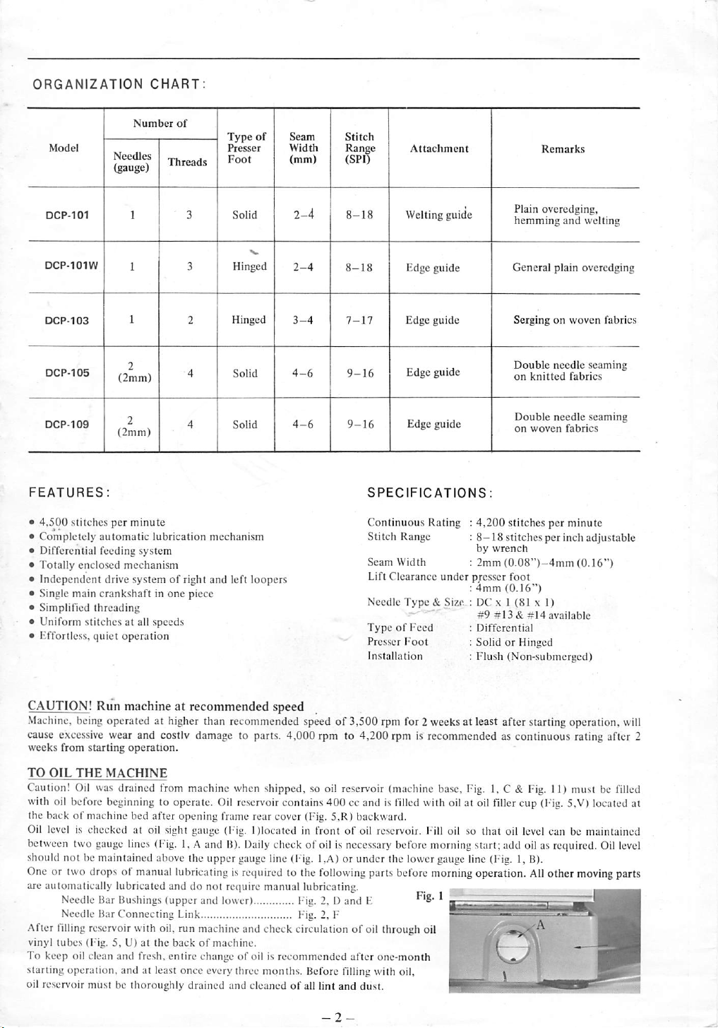
Oil
level
between
should
One
or
are
automatically
After filling
vinyl
To
keep
starting
oil
re.servoir
Run
being
operated
excessive
from
not
two
wear
starting
THE
MACHINE
Oil
was
before
beginning
of
machine
is
checked
two
gauge
be
maintained
drops
drained
lubricated
Needle
Bar
Bushings
Needle
Bar
Connecting
reservoir
lubes
(Fig.
5,
oil
clean
and
operation,
must
be
machine
operation.
and
at
at
higher
costiv
from
to
operate.
bed
after
at
oil
sight
lines
(Fig.
above
of
manual
lubricating
and
(upper
with
oil.
U)
at
the
back
fresh,
entire
and
at
least
thoroughly
recommended
than
recommended
damage
machine
opening
gauge
1, A and
the
do
Link
run
once
drained
to
when
Oil
reservoir
frame
(Fig.
B).
Daily
upper
gauge
is
required
not
rctiuire
and
lower)
machine
of
change
and
machine.
of
oil
every
three
and
cleaned
speed
speed
parts.
4,000
rpm
shipped,
rear
Dlocatcd
manual
check
is
months.
so
contains
cover
check
line
oil
400
(Fig.
in
front
of
oil
(Fig. 1 ,A)
to
the
following
lubricating.
Fig.
2. D and
I-'ig.
2,
circulation
recommended
Before
of
all
lint
of
3,500
to
4,200
reservoir
cc
and
5.R)
backward.
of
oil
reservoir.
is
necessary
or
under
parts
E
F
of
oil
after
one-month
filling
with
and
dust.
rpm
for 2 weeks
rpm
is
recommended
(machine
is filled
with
Fill
before
the
lower
before
through
oil
oil,
at
least
base.
Fig,
oil
at
oil filler
oil
so
morning
morning
gauge
line
start;
operation.
p'-
after
as
1, C &
that
oil
add
(Fig.
|
starting
operation,
continuous
Fig.
cup
level
oil
1,
B).
Ail
rating
11)
must
(F'ig.
5,V)
can
be
as
required.
other
moving
-jV
will
after
2
be filled
located
at
maintained
Oil
level
parts
Page 3

thread
needle
thread
for
left
looper
(DCP-IOIW,
105.
109)
TWO-NEEDLE
for
right
needle
bar
103
THREADING
•.uroad
for
for
Model
DCP-105 & 10 9 only
tension
needle
thread
(DCP-101.
bar
THREADING
for
needle
103,
only)
DIAGRAM
thread
(DCP-101.
for
right
105.
109
looper
only)
tension
right
looper
needle
spreader
(DCP-lW)
I thread
tension
eyelet
DCP-109
for
DCP-109
extension
only
only
holder
tension
left
looper
-6-
take-up
07723T15
Page 4

NEEDLE
Needles
type
Each
size
should
weight
Generally
weight
heavy
example
'TOO
Thread
eyes.
difficulty,
thread
TO
Turn
its
loosen
withdraw
Insert
the
nut
The
with
loosening
TO
LOOPERS
Threadings
DIAGRAM
to
the
unpacked
comes
Caution!
needle
TO
(Sec
The
by
threads
In
obtained
loosening
TO
FOOT
Pressure
thumb
clockwise
(W)
may
TO
Loosen
plate
proper
and
simultaneously
upper
screw
left
when
(K)
&
THREAD
for
DCP-lOO
DC X 1
(81 x 1),
needle
has
number
CHANGE
highest
front.
(G).
needle
THREAD
is
be
determined
of
material.
speaking
material,
weight
will
be
Needles
to
be
To
use
rough
will
breakage.
balance
wheel
position.
needle
needle.
needle
in
Holding
for
screw.
Inserting
or
tightening
stamped
material.
an
Type
used
interfere
THE
clamp
needle
DCP-105
(Sec
for
DCP-lOO
in
and
out
through
Draw
and
looper
2, 3 &
of
tension
should
for
by
page
thread
immediately
mounted,
about
tension
nut
be
DCP-lOO
tightening
tie a fresh
machine
REGULATE
1-ig.
amount
each
general
looper
REGULATE
(Sec
Fig.
of
presser
nut
(Fig.
or
downward.
anticlockwise
spoil
material.
REGULATE
thumb
(L)
to
left.
scam
width
left
slightly
as
is
and
of
knife
cover
with
required
move
knife
(M)
edge
upper
securely.
series
are
and
available
both a type
on
by
the
needle
size
of a size
#11
for
When
intelligible
DC x 1
Size
must
pass
or
uneven
with
NEEDLE
in
operating
With
nut
(Fig. 2 or
bar
as
it
THE
Page
6.
needle
eyes,
THE
4)
(Fig.
only
thread
3)
3.
W).
or
THE
screw
Loosen
is
screw
extension
is
far
in
position,
and
or
withdrawing
screw
NEEDLE.
6)
series
However,
with
the
and
and
two
inches
with
which
THREAD
on
needle
2,
H,
enougn
series
needle
tension
THE
PRESSURE
foot
on
To
increase
To
upward.
SEAM
(Fig.
screw
obtained.
(N)
lower
knife,
when
cover
extension
at
its
lowest
of
chrome
sizes
number
and a size
needle
shank.
size
of
thread
#9
is
No.
11"
through
or
stitch
recommended
and
needles,
thread
medium
ordering
order.
freely
thread,
proper
(Sec I ig. 2 or
direction
wrench,
as
3,
it
will
furnished
G)
go,
securely
109,
2-needle
needles
with
screw
driver.
RIGHT & LEFT
are
shown
the
simplest
end
of a thread
after
the
delivered
draw a thread
looper
eye.
(50mm)
to
start
TENSION
and
looper
Fig.
3,1
secure
proper
and
proper
stitch
to
tension
nuts
(Fig.
3,1
material
decrea.sc
Too
is
regulated
pressure,
pressure,
much
pressure
WIDTH
4,
K),
and
(M)
and
Lower
knife
is
turned,
and
so
no
seam
(P)
lateral
width
holder
slightly
position.
plated,
straight
are
9,
11,
number,
The
size
and
thickness
#14
for
the
or
'TOO
DC x 1
needle
which
formation
3)
until
needle
with
about
1/4
with
long
tighten
needle
machine,
is
simply
in
the
THREADING
way
of
originally
machine
until a fresh
of
thread
sewing.
threads
Fig.
4,
J).
stitch
formation
nut
(Fig.
and
Fig.
OF
PRESSER
by
turn
thumb
turn
on
presser
(Sec I ig
turn
Tighten
4)
swing
screw
will
move
upper
knife
adjustment
is
changed.
(O)
to
touches
upper
thumb
blade,
14
and
16.
and
a
of
needle
or
for
light
medium
following
#11"
and
looper
passes
with
or
cause
bar
is
at
machine,
turn
and
groove
to
clamp
is
clamped
made
by
threading
is
Tension
is
passed
in
is
thread
through
regulated
on
tormation.
will
be
2,
H)
and
4,
J).
means
of
nut
(W)
thumb
nut
foot
out
cloth
(N)
until
to right
will
move
on
Tighten
left
so
that
knife
screw
Q—-
I-"
H
%
V
Page 5

TO
REGULATE
In
general
produced
degree
and
To
regulate
(back)
is
out
frame
with
wrench,
upward
downward
main
changed.
To
To
move
amount
feeding
TO
In
move
plate
withdrawn
Cutting
surface
after
flush
avoided.
will
feeding
regulate
move
screw
of
ratio
CHANGE
preparation
cover
to
left.
edge
as
lower
of
lower
THE
main
feeding
and
differential
direction
main
positioned
rear
will
screw
downward.
shown
knife
of
stretch
feeding,
as
cover
(Fig.
furnished
increase
decrease
will
change
differential
(T)
upward
(T)
downward
main
feeding
is
changed.
THE
LOWER
for
removing
extension
Loosen
thumb
flush
of
lower
in
Fig.
is
set
knife
above
STITCH
determines
feeding
turn
close
with
stitch
stitch
slightly
feeding,
of
material
balance
to
5,
R)
machine.
length
length.
loosen
will
shrink
will
stretch
will
change
LENGTH
ratio
the
backward.
as
KNIFE
lower
knife,
holder
(0)
to
screw
(Q)
knife
must
7.
Be
sure
correctly.
or
Caution!
below
to
needle
(See
number
is
selected
to
wheel
front
To
and
to
Note
differential
screw
material
material.
slightly
(See
loosen
right
and
and
be
set
tighten
plate
Fig.
of
stitches
in
be
sewn.
until
main
as
possible.
Loosen
move
move
that
the
feeding
(T)
with
to
be
Note
as
Fig. 4 &
screw
swing
lower
knife
with
needle
thumb
To
set
cutting
surface
relation
amount
differential
5)
to
feed
Swing
screw
screw
screw
ratio
wrench.
sown.To
that
7)
(K)
and
out
cloth
will
plate
screw
(Q)
edge
must
be
to
dog
(S)
(S)
(S)
of
is
the
be
be
m-r-mm'
TO
CHANGE
To
remove
knife
upward.
knife
holder
cutting
edge
upper
knife
extend,
below
Tighten
TO
at
front
screw
SHARPEN
Dull
knives
grinder
sharp
is
shown
edge
rounded
in
in
THE
UPPER
upper
knife,
Upper
knife
(X)
with fingers
is
positioned
correctly,
its
cutting
(W)
should
front
bottom
edge
securely.
THE
UPPER & LOWER
immediately
accordance
Fig. 8 Note
is
required.
off
or
Upper
without
loosen
is
to
cutting
of
stroke,
of
with
the
sharp
KNIFE
screw
spring
pressed,
to
right,
in.scrt
the
right
edge
not
lower
knife,
be
replaced.
the
dimensional
part
of a double
or
lower
edge
should
(See
(W)
and
of
of
less
knife
Fig. 6 &
withdraw
so
pushing
upper
knife
lower
knife.
upper
knife
than
0.5mm-lmm
as
shown
KNIVES
Sharpen
knives
requirement
circle
whose
cutting
not
be
used.
7)
upper
upper
until
To
should
in
Fig.
(See
Fig.
where
edge
its
set
7.
8)
with
as
upper
knife
i
needle
surface
plate
Page 6

TO
SET
THE
Welt
guide
blindstitch
To
bottom
the
of
plate.
left.
securely.
Fig. 4 (Z)
needle
shown
welting
install
welt
of
welt
same
time,
needle
plate,
Turn
screw
After
welt
shows
plate.
WELT
GUIDE
in
Fig. 9 enables
operation
guide,
set
guide
holder
setting
groove
loosely
(d),
and
guide
is
the
Welt
(See
only
for
tubular
the
projected
into
groove
(b)
of
tighten
welt
correctly
screw
screw
guide
positioned,
Guide
completely
will
Fig. 4 &
model
work.
part
of
to
(c)
move
9)
DCP-101
(Fig.
9,
needle
plate
engage
with
from
under
slightly
tighten
installed
to
a)
at
the
and
groove
needle
right
and
screw
(c)
on
the
do
at
TO
SET
THE
Edge
guide
material
machine
This
model
of
needle
and
to
be
determined.
TO
(See
The
four
furnished
fi
xed.
groove
base
wood
Fig.
unwinder,
top
are
MOTOR
200W
clutch
rpm
DCP-lOO
When
PULLEY
following
shown
to
be
is
operated
edge
guide
DCP-101.
plate
move
edge
trimmed
Tighten
INSTALL
Fig.
11 & 12)
machine
(base-oil
machine
with
Be
sure
of
cushion
before
setting
screw.
12
shows
furnished
and
pressed
non-submcrgedly
PULLEY
output
motor,
on
50
cycles,
series
only a machine
must
List.
EDGE
GUIDE
in
Fig.
10,
trimmed
without
is
furnished
To
install
and
tighten
guide
(g)
or
seam
screw
THE
is
or
designed
trimmer.
edge
screw
right
and
width
when
(0
securely.
MACHINE
reservoir,
base
set
hooks
machine,
to
the
steel
(1/4
approximately
machines.
be
after
set
correctly a machine
rubber
installed
the
other
typical
installation
with
machine,
stand.
Note
installed
HP)
or
250W
(direct
3,400
is
recommended
head
prepared
is
by
(See
Fig.
10)
designed
with
(Fig.
the
side
to
regulate
for
edge
all
DCP-lOO
guide,
set
screw
(e)
securely.
left
until
operated
ON
iMg.
11)
11,
location
on
(Fig.
and
that
mounting
(1/3
rpm on
for
bought, a clutch
you
Loosen
the
width
without
THE
TABLE
must
Y)
and
on
base
set
the
bottom
11,
Y)
of
machine
clutch
motor
in
general
on
HP), 2 pole,
60
efficient
in
accordance
the
width
guide
when
series
(e)
into
screw
of
material
trimmer,
be
installed
wood
the
table
hook
with
of
machine
of
hook
head,
with
DCP-lOO
table
top).
individual
cycles
or
operation
motor
with
of
the
except
groove
(0
is
TOP
with
screws,
top
is
the
with
thread
table
series
2,850
of
and
its
the
C
d b
^
- -
—
-
J
H
Fig.
12
Gutch
Motor
Machine
3,500
3,500
4,200
4,200
Speed
rpm
rpm
rpm
rpm
Motor
Pulley
(Effective
dia.)
Motor
3,400
2,850
3,400
2,850
Speed
rpm
rpm
rpm
rpm
 Loading...