

Page 1

DC
DCDC
DC----7010
7010 7010
7010 Job Generator Utility
Job Generator UtilityJob Generator Utility
Job Generator Utility
Operation Manual
Page 2

Table of Contents
Table of ContentsTable of Contents
Table of Contents
1. Introduction
1. Introduction1. Introduction
1. Introduction ............................................................................................................................................ 1
2. How to execute the Job Generator Utility
2. How to execute the Job Generator Utility2. How to execute the Job Generator Utility
2. How to execute the Job Generator Utility ............................................................................................... 1
3. Main Setting Window
3. Main Setting Window3. Main Setting Window
3. Main Setting Window ............................................................................................................................. 2
3.1. New: To create a new application file.................................................................................................. 2
3.2. Open: To open an old application file. ................................................................................................. 2
3.3. Save: To save the current editing application file. ............................................................................... 2
3.4. Save As: To save the current editing application file to a new file. ...................................................... 2
3.5. Edit: To edit the current editing application file. ................................................................................... 2
3.6. Download: To receive files from PC. ................................................................................................... 2
3.7. Receive Data: To upload data to PC. .................................................................................................. 2
3.8. About: To display information pertaining to the Job Generator Utility. ................................................ 2
3.9. Exit: To close the Job Generator Utility. .............................................................................................. 2
4. Application Template
4. Application Template4. Application Template
4. Application Template ............................................................................................................................. 5
4.1. Form.................................................................................................................................................... 5
4.2. Menu ................................................................................................................................................. 12
4.3. Lookup .............................................................................................................................................. 14
4.4. Barcode ............................................................................................................................................. 15
4.5. Startup .............................................................................................................................................. 22
5. Receiving Data
5. Receiving Data5. Receiving Data
5. Receiving Data ..................................................................................................................................... 23
6. Chan
6. Chan6. Chan
6. Change Password
ge Passwordge Password
ge Password ................................................................................................................................ 25
7. Setting
7. Setting7. Setting
7. Setting .................................................................................................................................................. 26
7.1. Buzzer Pitch ...................................................................................................................................... 26
7.2. LCD Backlight ................................................................................................................................... 26
7.3. Auto Power Off .................................................................................................................................. 27
7.4. Set R.T.C. ......................................................................................................................................... 27
7.5. Deletion ............................................................................................................................................. 28
7.6. Prompting .......................................................................................................................................... 28
7.7. Key PAD LED (Reserved) ................................................................................................................. 29
8. Update Ke
8. Update Ke8. Update Ke
8. Update Kernel Firmware
rnel Firmwarernel Firmware
rnel Firmware ...................................................................................................................... 29
9. Get Kernel Version
9. Get Kernel Version9. Get Kernel Version
9. Get Kernel Version ............................................................................................................................... 30
10. Example Job Application
10. Example Job Application10. Example Job Application
10. Example Job Application .................................................................................................................... 30
10.1. Run the Job Generator Utility .......................................................................................................... 30
10.2. Download the Program Template file to the terminal ...................................................................... 39
10.3. Download the Lookup file to the terminal ........................................................................................ 39
10.4. Collecting Data ................................................................................................................................ 40
10.5. Uploading Data ............................................................................................................................... 40
Page 3

1
1
1. Introduction
1. Introduction1. Introduction
1. Introduction
The Job Generator Utility for Windows is a tool assistant for users to create their own data
collecting applications without developing program code. The utility can help user to simulate
the working sequences when developing applications on PC. The whole process of the
application development is just by keying parameters or required factors in the dialogue boxes
in the job generator utility and downloading it to the terminal. A new application can be
developed promptly and the job of collecting data can be started at once.
2. How to execute the Job Generator Utility
2. How to execute the Job Generator Utility2. How to execute the Job Generator Utility
2. How to execute the Job Generator Utility
Running the utility, the Main Menu, Figure 1 will be shown.
Main Menu, Figure 1
At this window, following two operational ways are available to lead the utility into Main Setting
Window.
Move the mouse cursor to any location on the picture of the terminal and click right button. or move the
cursor to the location of “PWR” key of the terminal and click left button.
Page 4
2
2
The Main Setting Window (figure 2) will be shown as below:.
Main Setting Window, Figure 2
3. Main Setting Window
3. Main Setting Window3. Main Setting Window
3. Main Setting Window
Main Setting Window comprises of a set of commands which are aimed to manage application
files such as create, save,...functions and communicate application files between PC and
terminal. The commands are listed below:
3.1. New: To create a new application file.
3.2. Open: To open an old application file.
3.3. Save: To save the current editing application file.
3.4. Save As: To save the current editing application file to a new file.
3.5. Edit: To edit the current editing application file.
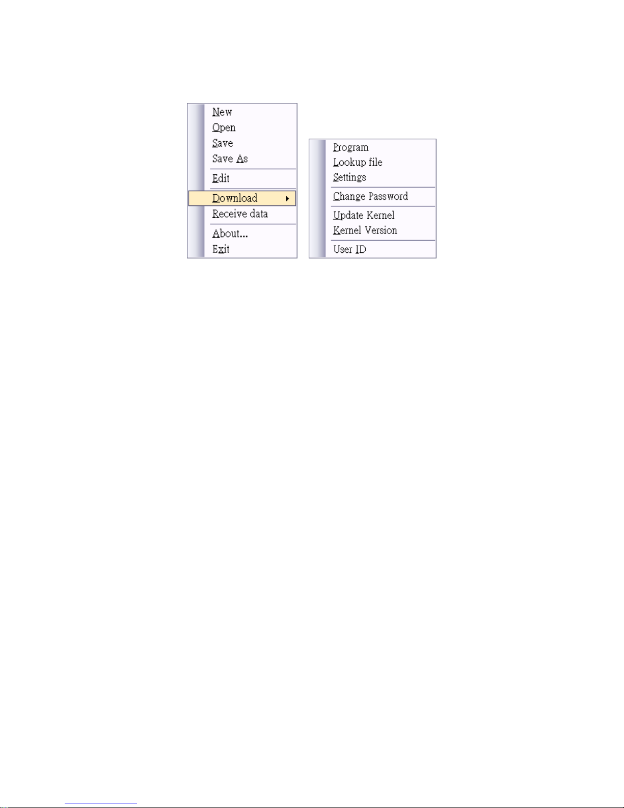
3.6. Download: To receive files from PC.
3.6.1. Program: To receive application file from PC.
3.6.2. Lookup File: To receive the lookup file(s) from PC.
3.6.3. Setting: To receive setting file from PC.
3.6.4. Change Password: To receive the password setting file from PC.
3.6.5. Update Kernel: To receive the kernel file from PC.
3.6.6. Kernel Version: To receive the kernel version file from PC.
3.6.7. User ID: Allow 5 levels login-account – one “Admin” level and 4 “User” level. There are
total 64 user ID can be set.
(please refer to the “Note: User ID:
Note: User ID: Note: User ID:
Note: User ID: Security
Security Security
Security Level
LevelLevel
Levelssss of Authority
of Authorityof Authority
of Authority”””” next page for
further information)
3.7. Receive Data: To upload data to PC.
3.8. About: To display information pertaining to the Job Generator Utility.
3.9. Exit: To close the Job Generator Utility.
Page 5
3
3
Note: User ID:
Note: User ID: Note: User ID:
Note: User ID: Security
Security Security
Security Level
LevelLevel
Levelssss of Authority
of Authorityof Authority
of Authority
The DC-7010 can assign different levels of authority to the users (at least 1 Admin user ID
and up to 64 IDs).
The User ID levels are as follow:
Admin:
Admin: Admin:
Admin: user ID of this level has full authority of the User IDs (create, edit and delete user
account, and change the levels of the entire users) and data management.
There should be at least 1 admin level user for the DC-7010 scanner.
User:
User:User:
User: there are 4 levels (level 1 to level 4) of user IDs for different users.
Level 1:
Level 1: Level 1:
Level 1: each user of this level has the authority to modify its own user name and
password. The users of this level can browse, delete, and edit the data as well.
Level 2:
Level 2:Level 2:
Level 2: each user of this level has the authority to modify its own user name and
password. Unlike Level 1 users, the users of this level can only browse, and
delete the data.
Level 3:
Level 3: Level 3:
Level 3: each user of this level has the authority to modify its own user name and
password. The users of this level can only browse the data and unable to
modify the scanned data.
Level 4:
Level 4: Level 4:
Level 4: the users of this level can operate the scan work only.
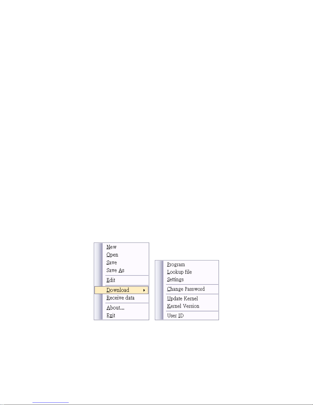
Step 1:
Right-click the mouse and activate the main menu.
Select Download>> and click on the “User ID” to access the function.
Page 6
4
4
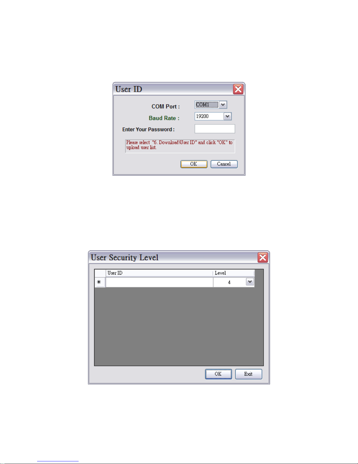
Step 2:
Select the proper COM Port, baud rate, password (if previously configured) to access the
function (make sure the DC-7010 unit is entering the USER ID menu as well.
Step 3
User can modify the user ID on this menu.
Admin Level Users can create, delete or modify the User ID and its Security Levels.
User ID: Numic Number recommended)
Level: Admin, and 1~4 (user)
Page 7
5
5
4. Application Template
4. Application Template4. Application Template
4. Application Template
Move the mouse cursor to the “New” item of the Main Setting Window (figure 2) and click mouse
left button, the Application Template, will be shown (figure 3).
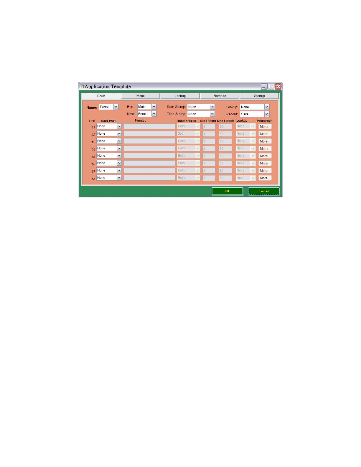
Application Template, Figure 3
The Application Template which includes Form, Menu, and Lookup, Barcode, and Startup settings
to formulate the application’s running sequence and data attributes.
The template can help user develop an application by clicking mouse button and entering
parameters or factors into the dialogue boxes.
4.1. Form
The Form is aimed to regulate the data attributes and make the path of the application's
routine. The user is requested to key in all the needed information in the dialogue boxes of the
template which may design the running sequence or may define data attributes.
There are up to 10 forms can be defined and every form can be defined up to 8 input fields
which contains maximum data length up to 50 characters.
4.1.1. Name:
Assign a name of the form (form ID). There are up to 10 name# can be assigned.
4.1.2. Esc:
Map out the running route of the form# to one of the next steps, “Main Menu” or “form#” or
“menu#”.
4.1.3. Next:
Map out the running route of the form# to one of the next steps, “Main Menu” or “form#” or
“menu#”.
Page 8
6
6
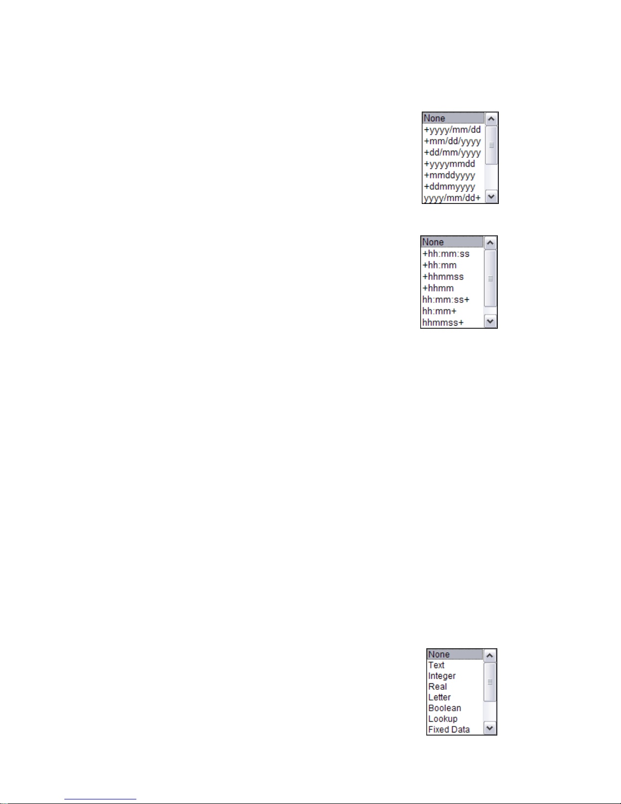
4.1.4. Date Stamp:
None: No Date Stamp appends to the record.
+yyyy/mm/dd: Date Stamp to be appended to the rear of the record
in the format of yyyy/mm/dd.
yyyy/mm/dd+: Date Stamp to be appended to the front of the record
in the format of yyyy/mm/dd.
4.1.5. Time Stamp:
None: No Time Stamp appends to the record.
+hh:mm:ss: Time Stamp to be appended to the rear of the record in
the format of hh:mm:ss.
hh:mm:ss+: Time Stamp to be appended to the front of the record in
the format of hh:mm:ss.
4.1.6. Lookup
Assign the form# to refer to which lookup file or not to do lookup function. One form refer to
one lookup file only if lookup function is enabled..
None: Not to enable the lookup function.
Lookup1: Refer to Lookup1 file.
Lookup2: Refer to Lookup2 file.
Lookup3: Refer to Lookup3 file.
4.1.7. Record
Save: Save is the default value. The data which collected in the field by running
the designed sequence in this form will be saved to record immediately.
Update Lookup: To update the lookup file that the form is current referred to.
Save & Update: Save the record to the data file also update the current lookup file which
the form is referred to.
Passdown: The form will not be saved as a data file. It will link to the next assigned
menu(s) or form(s).
4.1.8. Data Type:
None: The field is blocked, which does not allow any data key in.
Text: Allow any characters (e.g. &*abe123…) key in to the field.
Integer: Allow any integer (e.g. 12345…) key in to the field.
Real: Allow any real number (e.g. 1.23) key in to this filed.
Page 9

7
7
Letter: Allow any alphabet character (A to Z) key in to this filed.
Boolean: Allow only “0”,”1”,”y” or “N” key in to this field.
Lookup: This setting can call the Lookup at this manual designated as 4.1.6. to find a
referred file and to manage the key in data to check with referred lookup file.
Fixed Data: Prompts will be shown when the filed is presented at the terminal and the
prompts to be saved to record (data file).
Prompt: Prompts will be shown when the filed is presented at the terminal and the
prompts will not be saved to record (data file).
Counter: The record counts will be shown but not to save to record (data file).
Passdown: This field's data is from the preceding form or menu which Record
(please refer to 4.1.7 Record) type is defined as passdown.
Extension: Duplicate the preceding line's Data Type except the prompts in this filed.
This function is for data display purpose when preceding line doesn't have
enough space to display the content of data in the terminal. When data input is
over the space of the preceding line, the overflowed data would be shown at
this duplicate line. The maximum data length of proceeding filed minus
preceding field's prompt length is the maximum data length of this extension
line.
4.1.9. Prompt
Specify the heading of the input field.
4.1.10. Input Source
Assign the data input by keypad, scanner, or by both of them.
4.1.11. Min Length
Min Length can define the minimum length of the data. If set to “0”, then, it doesn't limit any
data input. Press “enter” to jump to next data input field if it intends to leave empty. If the min.
length is set over “0” and the input data number is less than set value, then the system would
give a warning message.
To purge the setting and re-define the length, press “ESC” to restart the job and input data
again.
4.1.12. Max Length
Max Length can define the maximum length of the data input (up to 50 digits).
If the data input is over the area that the field can display, then, the input data will be
left-scroll or the overflowed. The input data would be display to next the line if the line is set
Page 10

8
8
to Extension.
If the input data is over the maximum length setting there would have a warning message
Press “ESC” and input data again.
4.1.13. Lookup
Here the lookup field to be set to update or refer to the lookup file (4.1.6.) whenever the
matched lookup setting call at Data Type (4.1.8.) is called. One more important notice that if
the numeric input data comes a “+” or “-” symbol in front of it; it means any updated data will
be added or subtracted from the original lookup file. Please notice that it is designed the
lookup file data won't be subtracted to below “0”.
4.1.14. Properties
Move mouse cursor to the “Properties” item and click left button, the Properties, figure 4 will
be shown.
Properties, Figure 4
Page 11
9
9
Example
Fix data length: 10
Barcode data Display
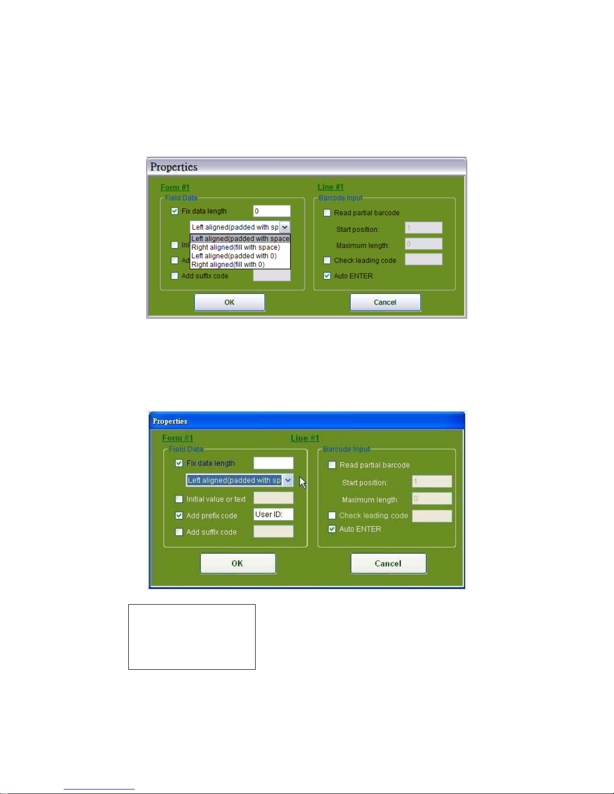
4.1.14.1. Fixed data length
It limits the length of the inputted data. Tick the box of “Fix data length,” and there are 4
options of alignment will be shown as shown in Figure 5.
Alignment Setup, Figure 5
4.1.14.1.2. Left aligned (padded with space)
In Figure 6, select “Left aligned (padded with space)”, the input data which is less than the
setting of data length will be filled with space.
Figure 6
Page 12
10
1
Example
Fix data length: 10
Barcode data Display
Example
Fix data length:10
Barcode data Display
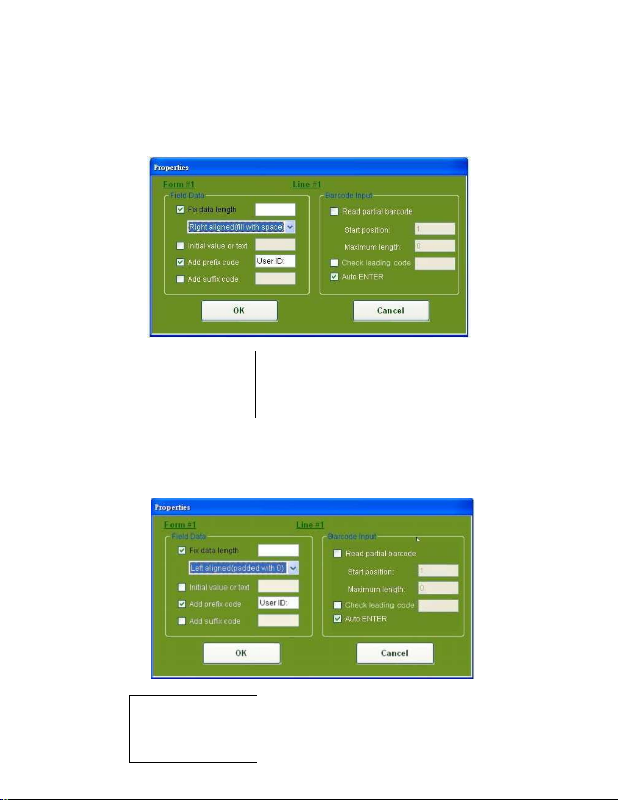
4.1.14.1.3. Right aligned (padded with space)
In Figure 7, select “Right aligned (padded with space)”, the input data which is less than the
setting of data length will be filled with space.
Figure 7
4.1.14.1.4. Left aligned (padded with 0)”
In Figure 8, select “Left aligned (padded with 0)”, the input data which is less than the setting
of data length will be filled with 0.
Figure 8
Page 13
11
1
Example
Fix data length: 10
Barcode data Display
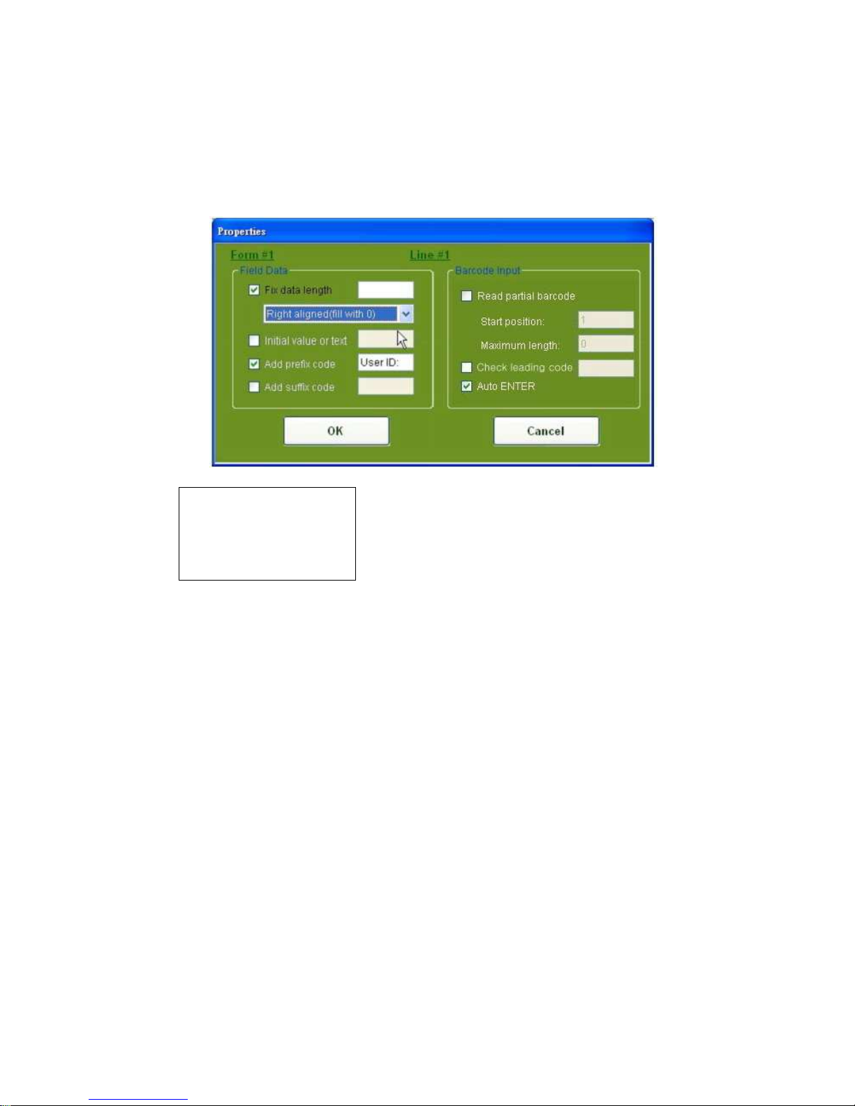
4.1.14.1.5. Right aligned (padded with 0)
In Figure 9, select “Right aligned (padded with 0)”, the scanned data which is less than the
setting of data length will be filled with space.
Figure 9
4.1.14.2. Initial value or text
Assign the initial value (default value) or text in the input field.
4.1.14.3. Add prefix code
Prefix code can be appended to the data. The prefix code can be any string (e.g.
BFR:345*&) or any a 3-digits decimal ASCII codes which is led by “\” (e.g. “\065\097” equals
to “Aa”).
Examples:
“\\” equals to “\”, “\n” or “\N” equals to “\010”, “r” or “R” equals to “\013”, or “\t” or “\T” equals to
“\009”, “\e” or “\T” equals to “\027”.
4.1.14.4. Add suffix code
Suffix the code can be appended to the data. The suffix code can be any string (e.g.
BFR:345*&) or any a 3-digits decimal ASCII codes which is led by “\”
(e.g. “\065\097” equals to “Aa”).
Page 14

12
1
Examples:
“\\” equals to “\”, “\n” or “\N” equals to “\010”, “r” or “R” equals to “\013”, or “\t” or “\T” equals to
“\009”, “\e” or “\T” equals to “\027”.
4.1.14.5. Read partial barcode
The barcode data can be displayed partially at the data field.
The default value of the field is 50 digits.
Start Position: Set the first digit of the barcode data to display at the data field.
The default value is from 1st digit.
Maximum Length: Set the maximum barcode data length at the data field.
The default value is 50 digits.
Example:
Start position Maximum length Barcode data Data Displayed
2 10 9876543210 876543210
2 3 9876543210 876
4.14.6. Auto ENTER
After reading barcode by scanner, an “ENTER” will be automatically executed and to move the
cursor to next field.
4.2. Menu
Move the mouse cursor to “MENU” and click left button to access the Menu Window
(as figure 10 below).
MENU, Figure 10
Page 15

13
1
The “Menu” is to help user on mapping out the running route as well as the descriptions of an
application. User is requested to key in all the needed parameters or required factors in the
blanks of the template which may portray the functions or may design the running sequence of
the application. There are up to 10 menus can be defined.
4.2.1. Name:
Assign a Menu # (Menu ID) of the current menu.
4.2.2. Esc:
Map out the running route to one of the next steps, “Main Menu” or “form#” or “menu#”.
4.2.3. Caption:
Assign a heading of the menu.
4.2.4. Data
Save Caption: This item provides selection to save or not to save the caption of the menu to
the record.
Save Selected Item: This item provides options to save or not to save the item name of the field
to the record.
Passdown: This item provides options to save or not to save the caption of the menu and
to save selected item of the field to the record.
Note
NoteNote
Note
To save captions, selected Item or both of them, the passdown item box
must be left blank.
4.2.5. Item No.
There are up to 10 item no. can be assigned.
4.2.6. Item Name
Assign the name of the field.
4.2.7. Next
Mapping out the running route of the “MENU” to steps are:
“Main Menu” , “form#” or “menu#”.
Page 16

14
1
4.3. Lookup
A lookup file is a database file which is the object to be referred, updated when the lookup file
is called. It is designed to a maximum of three lookup files in the system. The figure 11
indicates the lookup setting parameters below:
MENU, Figure 11
4.3.1 Name:
Assign which lookup file to be referred or edited.
4.3.2. Member length:
Assign the maximum record length for the lookup file.
4.3.3. Number of fields:
Assign the number of fields for the lookup file.
4.3.4. Field property:
Fixed length: Assign the data field is a fixed length.
Delimiter: Assign a delimiter, an ASCII code, to separate the data filed.
4.3.5. Lookup data can be uploaded:
Assign the lookup data to be uploaded to PC only.
Page 17

15
1
4.3.6. Action when the input has no match:
Choose one of the actions below in case of the input data is not match in the lookup file.
Continue: The operation will be progressed to next input field without any halt or any
message warning.
Show Warning Messing: The operation will be halted and a warning message is shown.
Append to lookup file: The current recode will be appended to the lookup file.
Show Warning Message & Append: A warning message will be shown and the current
recode will be appended to the lookup file.
4.3.7. Field:
There are maximum 8 fields can be set.
4.3.8. Offset:
Assign the start position for each field for the lookup file.
4.3.9. Length:
Assign the length for each field, maximum 50 digits, of the lookup file.
4.3.10. Key field:
The key field is aimed to find the matched data in the lookup file. Only one key field can be
set among the Fields (4.3.7.).
4.4. Barcode
Move the mouse cursor and click left button to access the “Barcode” menu.
The Barcode Windows offer parameters for user to set the required settings to applications.
Page 18

16
1
4.4.1. Code39
4.4.2. Interleaved 2 of 5
4.4.3. Code 128
Page 19

17
1
4.4.4. Code 11
4.4.5. Code 93
Page 20

18
1
4.4.6. MSI-Plessey
.
4.4.7. CODA BAR / NW7
4.4.8. EAN-13 / JAN-13
Page 21

19
1
4.4.9. UPC-A
4.4.10. EAN-8 / JAN-8
4.4.11. UPC-A
4.4.12. ISBN / ISSN
Page 22

20
2
4.4.13. CODE ID
4.4.14. GS1
4.4.15. Industrial 2 of 5 / ITIA
Page 23

21
2
4.4.16. Matrix 2 of 5
4.4.17. CHINA POSTAGE
Page 24

22
2
4.5. Startup
Move the mouse cursor to the “Startup” tap button and click left button (Figure 12).
Startup, Figure 12
The Startup can specify the location where the application to be started from and the format of
record. The user is requested to key in parameters or the required factors in the dialogue
boxes of the template.
4.5.1. Program start from
Page 25

23
2
Assign the application where to start from, either from form# or menu#.
4.5.2. Data field delimiter
Assign the number of delimiter(s) of the data field either by one digit or two digits.
4.5.3. ASCII Value
Assign delimiter ASCII value.
4.5.4. Text
Assign delimiter text.
Note:
Note: Note:
Note:
The editing Application Template, when “OK Button” is pressed, the setting is saved to
memory only (it is not saved to the file). While “Cancel Button” is pressed, the setting won’t be
saved to memory or saved to file. The editing Application Template which saved at memory
can be recalled by pressing “PWR” key, then select “Edit” to recall the editing Application
Template.
5. Receiving Data
5. Receiving Data5. Receiving Data
5. Receiving Data
At Main Setting Window (figure 2) move the mouse cursor to the “Receive Data” item and click
the left button. The Receive Data Window, figure 13 will be shown.
Receive Data, Figure 13
Page 26

24
2
There are two interface cables available for connecting the terminal to PC: USB (serial) and
RS-232. Set the COM Port and Baud Rate then click “OK” to confirm.
Suggestion
Suggestion Suggestion
Suggestion
BBBBefore click “OK” button, user has to double check if the terminal is uploading file
efore click “OK” button, user has to double check if the terminal is uploading fileefore click “OK” button, user has to double check if the terminal is uploading file
efore click “OK” button, user has to double check if the terminal is uploading filessss and the
and the and the
and the
cable is
cable is cable is
cable is properly
properly properly
properly connected
connected connected
connected to
toto
to PC and the terminal
PC and the terminalPC and the terminal
PC and the terminal.
. .
.
A dialog box, View Data (figure 14) will be shown as below:.
View Data Selection, Figure 14
User can view the collected data by simply click “Yes” button and review the data.(figure 15).
Reviewing Data, figure 15
If user doesn't want to view the collected data, then, click “N” button, the collected data would
be saved to the designated file.
Page 27

25
2
6. Change Password
6. Change Password6. Change Password
6. Change Password
At Main Setting Window (figure 2), move the mouse cursor onto the “Download” item and click
the left button, and then move the mouse cursor onto “Change Password” item and click the
left button. The Change Password Window will be shown (figure 18).
Change Password, Figure 18
The password length is up to 10 characters, and lower case a~z, upper case A~Z, and 0-9 are
allowed. The password would be changed only after the current password verified. When
setting up a password for the first time, leave the “Current Password” item blank, and fill in the
“Your New Password” item and the “Confirm New Password” item accordingly.
After the password is configured, any communication between the terminal and PC would request
password verification.
When the “Memorize Password” function is enabled; user need not to enter the password every
time when terminal works to communicate with PC.
Page 28

26
2
7. Setting
7. Setting7. Setting
7. Setting
At Main Setting Window (figure 2), move the mouse cursor onto the “Download” item and click
the left button, and then move the mouse cursor onto the “Setting” item and click the left
button. One of the Download Setting window, figure 14~17, will be shown.
7.1. Buzzer Pitch
The buzzer’s pitch can be adjusted to meet user’s optimal needs. At the figure 14, the bar
represents the pitch value, between 0~255 Hz. User just need to drag the arrow to travel it to
any position in the bar, while the bar is traveling, the small window shows a rotated number
which represents the pitch value. User can use “Test” item to try out the best value of the pitch
before save it as a file or download it to the terminal.
Figure 19
7.2. LCD Backlight
The LCD backlight can be switched off in the pre-defined period of time without press any
keypad or do a scan on the terminal. At the figure 20, the bar represents pre-defined LCD
backlight off time value (0-60 second). Drag the arrow to travel it to any position in the bar,
while the bar is traveling, the small window shows a rotated number which represents the
pre-defined off time value. To set the backlight always on, click the “Always On” item.
User can save it as a file or just download it to the terminal. Factory default is off.
Page 29

27
2
Figure 20
7.3. Auto Power Off
The terminal can be set to auto power off in the pre-defined period of time without press any
keypad of do a scan on the terminal. At figure 21, the bar represents pre-defined off time
value, 0-60 minute. User just need to drag the arrow to travel it to any position in the bar, while
the bar is traveling, the small window shows a rotated number which represents the
pre-defined off time value. User is also able to set the terminal always on by click the “Disable”
item. User can save it as a file or just download it to terminal.
Figure 21
7.4. Set R.T.C.
The terminal’s real time clock has to synchronize with host PC. At the figure 22, user can save
it as a file or just download it to the terminal.
Page 30

28
2
Figure 22
7.5. Deletion
The collected data would be deleted from terminal after the data transmission completes
automatically. Referring to the figure 23, user can activate the delete function by ticking the
box.
Figure 23
7.6. Prompting
The number of records will show on the screen as in figure 24 by setting the lasting time.
Simply drag the arrow on the bar as shown in figure 24 from 0 to 9999 seconds.
Record #0001
Page 31

29
2
Figure 24
7.7. Key PAD LED (Reserved)
The function is reserved and not functioning.
8. Update Kernel Firmware
8. Update Kernel Firmware8. Update Kernel Firmware
8. Update Kernel Firmware
User can update kernel firmware of the terminal.
Before update the firmware, please make sure the cradle and PC are properly connected.
Make sure the terminal is properly placed onto the cradle.
Be careful to prevent the communication breakdown or other events that interfere in the
communication while firmware is being up-dated.
Note:
Note: Note:
Note:
Please quit other programs on your PC before update.
Please refer to the qualified personnel to update the firmware.
Any failures happen during the update process or bad connections may cause terminal
halt-on.
Page 32

30
3
Figure 25
9. Get Kernel Version
9. Get Kernel Version9. Get Kernel Version
9. Get Kernel Version
User can get the kernel version from the terminal.
Figure 26
10.
10. 10.
10. Example
Example Example
Example of
ofof
of Job Application
Job ApplicationJob Application
Job Application
The chapter aims to tutor how to design an application. There is a Program Template File at
CD disk, its file name is Pegasus.apg which is the example file to guide user how an
application be designed.
Assuming that the application consists of user identified number, location, item no. item, and
quantity variables and the working flow of the application is framed as below:
10.1. Run the Job Generator Utility
The Main Menu figure will be shown on the PC.
Page 33

31
3
Main Menu, Figure 1
Move the mouse cursor to any location on the picture of the terminal (figure 1), and click right
button, or
Move the mouse cursor to the location of “PWR” key of the terminal (figure 1), and click left
button.
When one of those two above mentioned operational ways is performed, the Main Setting
Window, figure 2 will be shown.
Page 34

32
3
Main Setting Window, Figure 2
At figure 2, select “OPEN” item first and to read the example file, Pegasus.apg. After reading
the Pegasus.apg file, the following figure will be shown on the PC.
Figure 26
The figure 26 shows the detailed settings of form1 at the Application Template.
Those settings are described as below:
Name: Form1 – this form’s ID
Esc: Menu1 – when an “Esc” command is called, the application would head into
Menu1.
Next: Form2 – when a “next” command is called, the application would head into
Form2.
Date Stamp: +yyyy/mm/dd – the date stamp would be appended to the rear of record.
Time Stamp: +hh:mm:ss – the time stamp would be appended to the rear of record.
Lookup: None is the default value. The form won’t refer to any lookup files.
Record: Save is the default value.
The form of each line (Line #1 ~Line #10) will be saved to record immediately after collection.
Data Type: Text – allow any characters (e.g. &*abe123…) to be inputted into the field.
Prompt: Empl. ID: the prompt represents an employee identified number.
Input Source: the data key-in is allowed by scanner or keypad. If the data is inputted by
scanner, then the “ENTER” is automatically executed while the data key-in is
by keypad, then the “ENTER” has to be pressed by operator to complete the
key-in process.
Min Length: 1 – the number of the data is not less than 1 digit.
Page 35

33
3
Max Length: 50 – the number of the data is not more than 50 digits.
Lookup: None - The field of this form will not refer to any lookup file’s field.
Properties: please refer to the figure below (figure 27).
Figure 27
Figure 27 shows that the prompt of “Empl. ID:” would be saved as prefix to the record.
And the “ENTER” will be executed when a data key-in is by scanner.
When finishes form1 setting. Move the mouse cursor to Name Com Box and click the left
button to drop down more form# selections. The following figure 28 will be shown on the PC.
Figure 28
Select the form2 and click left button. The following figure will be shown below
Page 36

34
3
(figure 29).
Figure 29
The figure 29 shows detailed settings of form 2 at the Application Template.
Those Settings are described as below:
Name: Form2 – this form’s ID
Esc: Menu1 – when an “Esc” command is called, the application will head into Menu1.
Next: Form2 – when a next command is called, the application will head into Form2.
Date Stamp: +yyyy/mm/dd – the date stamp would be appended to the rear of record.
Time Stamp: +hh:mm:ss – the time stamp would be appended to the rear of record.
Lookup: Lookup1: The form will refer to lookup file1.
Record: Save: The form will be saved to record after collection immediately.
Data Type: Text – allow any characters (e.g. &*abe123…) to be inputted in the field.
Prompt: Location: the prompt represents the locations.
Input Source: data key-in is allowed by scanner or by keypad. If the data is key-in by
scanner, then the “ENTER” is automatically executed while the data key-in is
by keypad, then the “ENTER” key has to be pressed by operator to complete
the key-in process.
Min Length: 1 – the number of the data is not less than 1 digit.
Max Length: 50 – the number of the data is not more than 50 digits.
Properties: please refer to figure 30.
Page 37

35
3
Figure 30
*At this setting, an “ENTER” will be automatically executed when a data key-in is by scanner.
Prompt: Item No: -- the prompt represents the item no.
Input Source: data key-in is allowed by scanner or keypad. If the data is inputted by
scanner, then the “ENTER” is automatically executed while the data key-in is
by keypad, then the “ENTER” key has to be pressed by operator to complete
the key-in process
Min Length: 1 – the number of the data is not less than 1 digits.
Max Length: 50 – the number of the data is not more than 50 digits.
Properties: please refer to figure 31
Figure 31
*At this setting, an “ENTER” will be automatically executed when a data key-in is by scanner.
Page 38

36
3
Prompt: Item name: -- the prompt represents the item’s name.
Input Source: data key-in is allowed by scanner or keypad. If the data is inputted by
scanner, then the “ENTER” is automatically executed while the data key-in is
by keypad, then the “ENTER” key has to be pressed by operator to complete
the key-in process.
Min Length: 1 – the number of the data is not less than 1 digits.
Max Length: 50 – the number of the data is not more than 50 digits
Properties: please refer to the figure 32
Figure 32
When setting proprieties, an “ENTER” will be automatically executed when a data key-in is by
scanner.
Prompt: Qty: -- the prompt represents the quantity.
Input Source: keyboard – The information can be entered by Keypad Only
Keypad OnlyKeypad Only
Keypad Only,
the “ENTER” key has to be pressed by operator to complete the process.
Min Length: 1 – the number of the data is not less than 1 digits.
Max Length: 10 – the number of the data is not more than 10 digits.
Properties: please refer to the figure 33
Page 39

37
3
Figure 33
When setting proprieties, an “ENTER” won’t be automatically executed when a data key-in is
by keypad. User has to press “enter” to complete the data input.
When form2 setting is finished, move the mouse cursor to Menu.
Tab Button and click the left button. The following figure will be shown on the PC.
Menu1 is the first of the Application Template. Those settings are described as below:
Name: Menu1 – this menu’s ID.
Esc: Main – when an “Esc” command is called, the application would head to Main
Menu.
Caption: <PEGASUS Inventory> -- the heading of the application.
Date Checkbox: Select “Passdown: " and the menu’s information won’t be saved to record.
Item Name: “>Check Stock” and “>Exit” -- are prompts.
Next: “item1” is set the application heads to form1 and “item2” is set application heads to
Main Menu.
When menu setting is finished, move the mouse cursor to Lookup Tab Button and click the left
button. The following figure will be shown on the PC.
Page 40

38
3
Figure 35
Figure 35 shows detailed settings of Lookup. Lookup1 is the first of the Application Template.
Those settings are described as below:
Name: Lookup1 – define lookup’s ID.
Member length: lookup file's length.
Number of fields: field's length.
Field property: Fixed length-- field's length is set to” fixed” to separate every field's data.
Delimiter-- field's length is separated by delimiter.
Lookup data can be uploaded: Lookup data can be uploaded to PC.
Action when the input has no match: Continue – The operation will be progressed to next input
field without any halt or any message warning.
Offset: the start position for field data.
Length: the length of the field data.
Key field: find the matched data in the lookup file.
Page 41

39
3
10.2. Download the Program Template file to the terminal
At the Main Setting Window (figure 36), select the “download” item then program item, the
Download AP Template figure will be shown.
Figure 36
User has to select correct COM Port and proper
Baud Rate, and enter information into blanks.
However, before click “OK” button, user has to
However, before click “OK” button, user has to However, before click “OK” button, user has to
However, before click “OK” button, user has to
double check if the terminal is at receiving file state
double check if the terminal is at receiving file state double check if the terminal is at receiving file state
double check if the terminal is at receiving file state
and if the cable is connected firmly between
and if the cable is connected firmly between and if the cable is connected firmly between
and if the cable is connected firmly between the PC and the terminal.
the PC and the terminal. the PC and the terminal.
the PC and the terminal.
The route to get to the state of the terminal to receive the program template file is via main
menu\download\ program\enter.
10.3. Download the Lookup file to the terminal
At the Main Setting Window, select the “download” item then Lookup file item, the Download
Lookup file figure will be shown.
Figure 36
User has to select correct COM Port and proper
Page 42

40
4
Baud Rate and enter information into blanks
However, before click “OK” button, user has to double check if the term
However, before click “OK” button, user has to double check if the termHowever, before click “OK” button, user has to double check if the term
However, before click “OK” button, user has to double check if the terminal is at receiving file
inal is at receiving file inal is at receiving file
inal is at receiving file
state and if the cable is connected firmly between the PC and the terminal.
state and if the cable is connected firmly between the PC and the terminal. state and if the cable is connected firmly between the PC and the terminal.
state and if the cable is connected firmly between the PC and the terminal.
The route to get to the state of the terminal to receive the lookup file is via main
menu\download\ Lookup\enter.
10.4. Collecting Data
When finishes the program template files downloading, the terminal is already equipped with
the user’s defined application, Pegasus Inventory. The way to enable the Pegasus Inventory
application terminal is via the route of main menu\collect data\enter.
10.5. Uploading Data
Users will need to upload the collected data to PC when the data collection tasks are finished.
At PC side, user has to run the Main Setting Window, figure 2, select the “Receive data” item
and Receive Data figure will be shown.
Figure 37
User has to select correct COM Port and proper Baud Rate and enter information into blanks
However, before click “OK” button, user has to double check if the terminal is at the status of
However, before click “OK” button, user has to double check if the terminal is at the status of However, before click “OK” button, user has to double check if the terminal is at the status of
However, before click “OK” button, user has to double check if the terminal is at the status of
uploading file state and if the cable is connected firmly between
uploading file state and if the cable is connected firmly between uploading file state and if the cable is connected firmly between
uploading file state and if the cable is connected firmly between the PC and the terminal.
the PC and the terminal. the PC and the terminal.
the PC and the terminal. The
route to get to the state of the terminal to upload the data is via main menu\upload data\enter.
When finishes the uploading task, the following figure will be shown on the PC.
Page 43

41
4
Figure 38
 Loading...