

Page 1
TAPE
CUTTER
FOR
THE
NEW
WILLCOX
&
GIBBS
TK
500
SERIES
SERIES
WILLCOX
GJII3E33JflC.
Page 2

Page 3
TABLE
C0NhihINlr5
OF
Page
I
ASSII’IC.NI
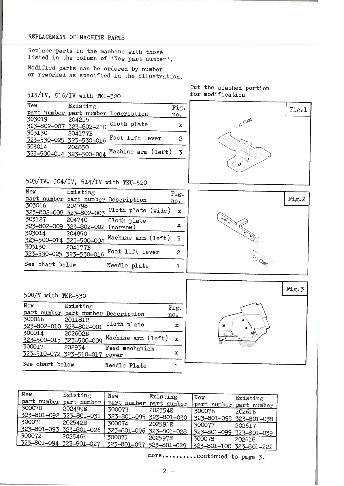
l?[IP.LAOENEN11OF
sis/iv,
505/IV,
500/V
PREPAEAq
1
I0N
515/IV,
503/TV,
soo/v with
INSTALLATION
515/TV,
503/TV,
500/v
INSTALLATTON
ECA—300/01 ECA—300/02
ACA—l00/10
PARTS
LTST
TKIJ—520
ECA—300/01
ACA—100/10
[ON
with
OP
with
OP
TK
MACHINE
510/TV
504/TV,
TKR—550
MACHINE
sio/iv
504/Tv,
TKR—550
TAPE
OF
510/TV
504/Tv,
TKR—530
OP
DRTVING
TKU—520
ECA—300/02
TAPE
PARTS
with
514/fl!
AND
with
514/Tv
CUTTER
with
514/Tv
UNIT
TKR—550
CUTTE
rp(1J_520
T}CU—520
TKU—520
ES
.
with
PARTS
with
with
TK1J—520
TKtJ—520
TICfJ—520
•
1
2
2
2
2
5
5
3
3
4—5
4
5
5
6—7
6
7
8—13
8—9
10—11
12—13
*
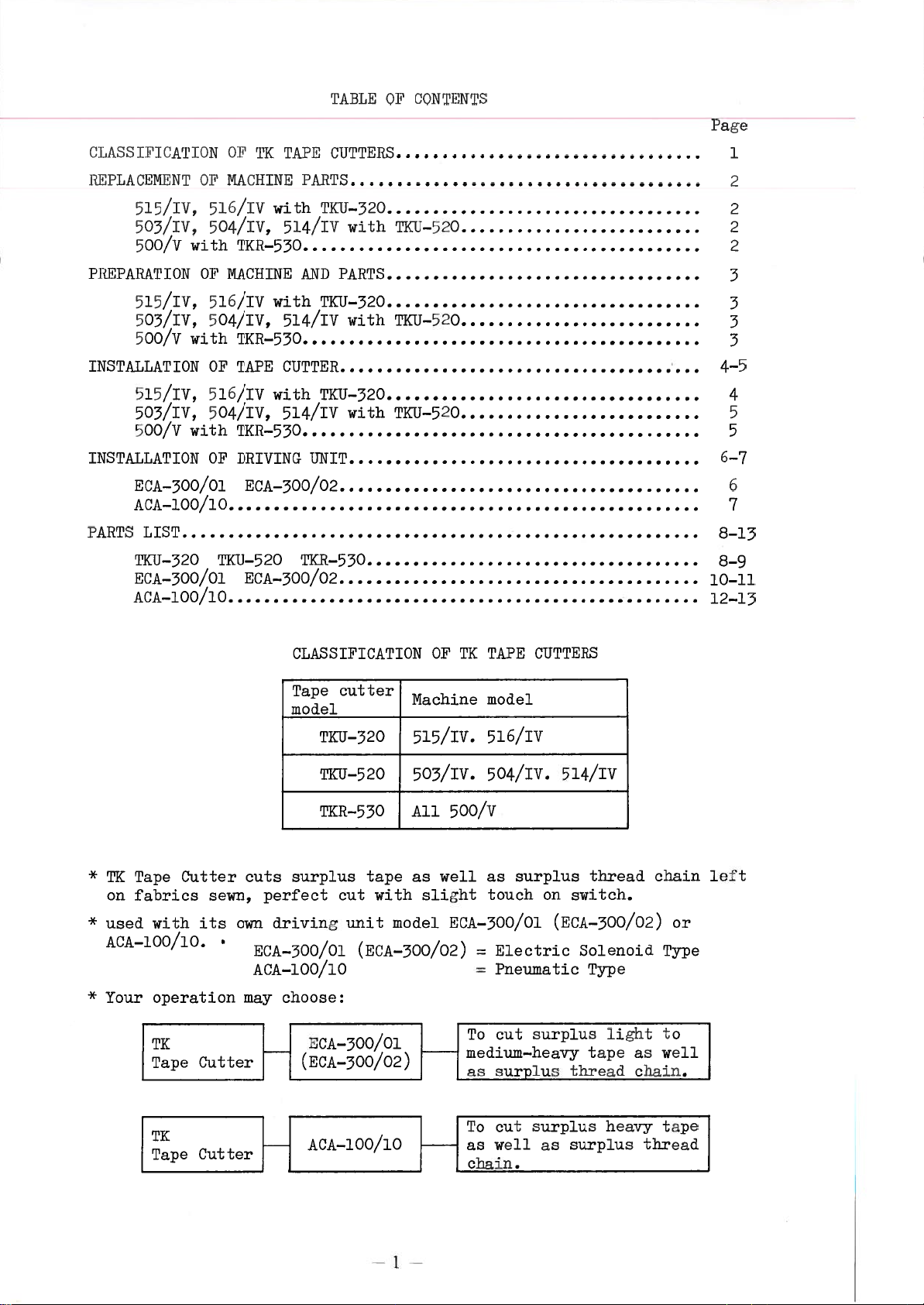
TK
Tape
on
fabrics
*
*
used
with
ACA—lOO/lO.
Your
operation
I
TK
Tape
Cutter
its
Cutter
sewn,
own
CLSTFICATI0N
Tape
model
surplus
cuts
perfect
driving
ECA—300/0l
ACA—l00/lO
choose:
may
(ECA—500/o2)
H
cutter
TKU—320
TKU—520
TKR—530
tape
cut
with
unit
(ECA—500/02)
ECA—soo/ol
Machine
515/Tv.
503/Tv.
All
as
model
OF
TK
500/v
well
slight
ECA—300/0l
I
1
TAPE
model
516/Tv
504/Tv.
as
touch
=
=
To
medium—heavy
as
CUTTERS
surplus
on
Electric
Pneumatic
surplus
cut
surplus
(ECA—300/02)
514/Tv
thread
switch.
Solenoid
Type
tape
thread
light
chain
as
chain.
left
or
Type
to
well
I
cut
TK
Tape
Cutter
ACA—lOO/lO
To
I
as
j
chain.
1
well
surplus
as
surplus
heavy
tape
thread
Page 4
I?l
PtA
CNN
lINt
kepi
ace
par
ic
ted
in
NodlIjed
or
reworked
515/IV,
5l/IV
New
pgrt.
number
303019
323—802—007
303130
323—550—025
303014
325—500—014
0.1’
MACI
to
jo
tiLe
the
cci
iunii
artu
can
no
opeciCied
with
Nxis
part
204215
ting
number
525—802—210
204l77B
323—550—016
204850
325—500—004
TiN
N
PACTS
maclime
ol
be
ordered
TXU—320
Foot
Machine
with
‘New
part
by
in
the
Description
c
th
0
pae
lift
those
number’
number
illustration.
1
t
lever
arm
/
tleft)
Fig.
no.
Cut
the
for
slashed
modification
portion
x
2
3
503/IV,
504/IV,
New
number
phrt
303066
325—802—008
303127
3
.Sr8O2—OO9
303014
323—500—014
303130
323—530—025
See
chart
500/V
with
New
part
number
300066
3?3—802—OlO
300014
323—500—015
300017
323—510—072
See
chart
Existing
part
204798
325—802—003
204740
323—802—002
204850
323—500—004
2041773
323—530—016
below
TKR—530
Existing
part
2011810
323—802—001
2026023
323—500—009
202934
323—510—017
below
514/IV
number
number
with
T}—520
Description
Cloth
Cloth
(narrow)
Machine
Foot
lift
Needle
Description
Cloth
Machine
Feed
mechanism
cover
Needle
plate
plate
plate
plate
Plate
arm
arm
lever
(left)
(wide)
(left)
Fig.
no.
Fig.
no.
Fig.2
x
X
3
2
1
x
x
x
1
7Q
New
J
part
number
300070
f
L323—sol—o92
300071
I
323—801—093
300072
2
—801—094
Existing
part
number
202499E
323—801—031
202542E
323—801—026
202546E
323—801—027
New
part
number
300073
323—801—095
300074
33—801—096
300075
323—801—097
I
Existing
part
number
202554E
323—801—030
202596E
323—801—028
202597E
323—801—029
more
—
INew
part
300076
323—801—098
300077
23—801—099
300078
323—801—100
continued
number
Existing
part
number
202616
323—801—038
202617
323—801—039
202618
323—801—222
to
page
3.
Page 5
PkI
ACA.PTON
0i
MACI
[[N
N
ANPPAi?’1
1
S
Remove
to
LI
OWi
515/TV,
Pro
1.
Cloth
2.
Needle
3.
Machine
4.
Poot
5.
*
replace
shown
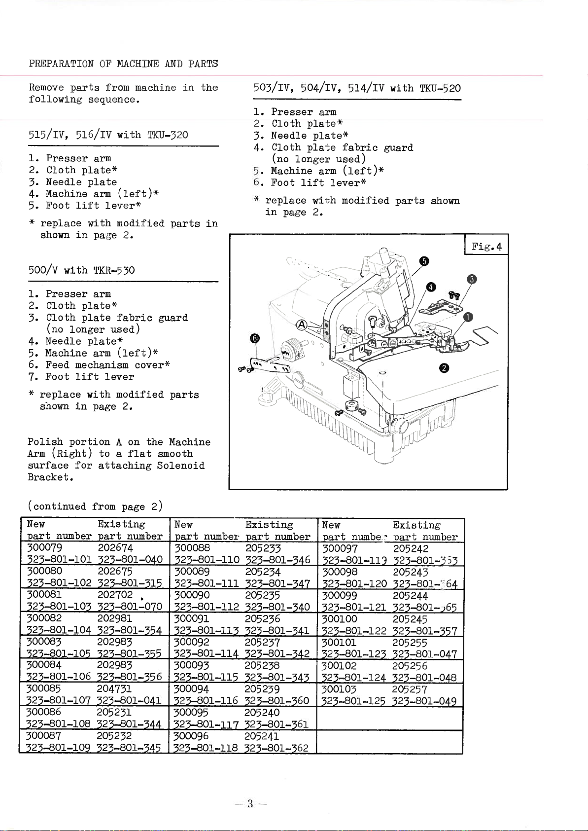
500/V
1.
Presser
2.3.Cloth
Cloth
(no
Needle
4.
Machine
5.
6.
Feed
Foot
7.
*
replace
shown
par
I
51h/IV
sser
plate*
lift
with
in
with
plate*
plate
longer
plate*
mechanism
lift
with
in
from
hi
iiecf
UeIiCe.
with
arm
plate
(icyt)*
arm
lever
modified
pae
TKR—530
arm
fabric
used)
(left)*
arm
lever
modified
page
2.
2.
niacitine
TI1
X—320
cover*
parts
guard
parts
in
the
in
505/IV,
1.
Presser
2.
Cloth
Needle
5.
Cloth
4.
(no
Machine
5.
6.
Foot
*
replace
in
504/IV, 514/IV
arm
plateX
plate*
plate
longer
arm
lift
lever*
with
page
2.
fabric
used)
(left)X
modified
with
guard
parts
TKtJ—520
shown
Fig.4
0
Polish
Arm
surface
portion
(Right)
forattaching
Bracket.
(continued
New
part
number
300079
323—801—101
300080
323—801—102
300081
523—801—103
300082
525—801—104
300085
325—801—105
300084
523—801—106
300085
525—801—107
500086
523—801—108
300087
323—801—109
on
A
to
flat
a
from
page
Existing
part
number
202674
523—801—040
202675
323—801—315
202702
•
323—801—070
202981
523—801—354
202983
523—801—355
202983
323—801—35
204731
323—801—041
205251
323—801—344
205232
523—801—345
the
Machine
smooth
Solenoid
2)
New
part
number
300088
523—801—110
300089
325—801—111
500090
325—801—112
500091
323—801—115
500092
325—801—114
300095
6
525—801—115 325—801—345
300094
325—801—116
500095
323—801—117
500096
325—801—118
205238
205239
325—801—560
205240
323—801—361
205241
323—801—562
Existing
part
number
205233
325—801—346
205234
323—801—547
205255
323—801—540
205236
New
part
numbe
300097
323—801—119
300098
525—801—120
300099
323—801—121
300100
323—801—341 525—801—122
205237
523—801—342
500101 205255
523—801—123 325—801—047
300102 205256
523—801—124
300105
323—801—125
Existing
number
part
205242
323—80l—3
205243
323—80l—4_
205244
525—801—)
65
205245
323—801—557
323—801—048
205257
323—801—049
Page 6
jN’lAllAl’
ON
Of
TAPf
(GJ’lt’lH?
ivszeni
515/IV,
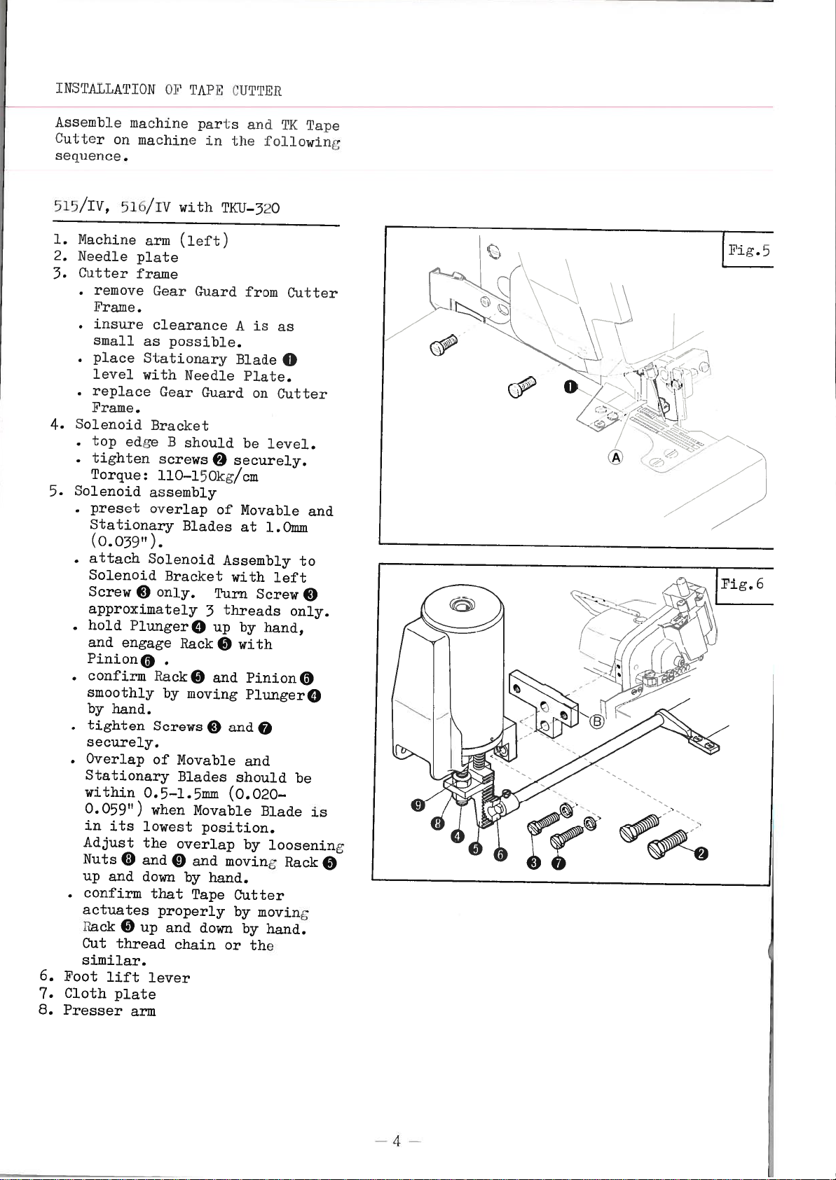
1.
2.
3.
4.
5.
6.
7.
B.
Pu
I
(H’
sequel
Nachurie
Needle
Cutter
•
•
•
Solenoid
•
•
Solenoid
•
•
attach
Solenoid
Screw
approximately
•
hold
and
PinionO
•
confirm
smoothly
by
•
tighten
securely.
•
Overlap
Stationary
within
0.059”)
in
Adjust
Nuts
up
•
confirm
actuates
kack
Cut
similar.
Foot
Cloth
Presser
b
I
e
lOLcI
00
Ce.
siu/iv
remove
‘rare.
insure
small
place
level
replace
Frame.
top
edge
tighten
Torque:
preset
Stationary
(0.039”).
Plunger
engage
hand.
its
0
and
0
thread
lift
plate
arm
Li
ie
IILCIIiIIe
with
arm
(lef
plate
frame
Kear
clearance
as
possible.
Stationary
with
Needle
Gear
Bracket
B
should
screws
110—150kg/cm
assembly
overlap
Blades
Solenoid
Bracket
only.
0
0
Rack
Rack
0
by
moving
Screws
of
Movable
Blades
0.5—1.5mm
when
lowest
the
overlap
and
dawn
up
lever
0
that
properly
and
chain
and
by
Tape
Li’
tO
in
TI<U—320
t)
Guard
Guard
0
of
Assembly
Turn
threads
3
up
0
and
and
0
(0.020—
Movable
position.
moving
hand.
dom
or
and
lie
lot
from
is
A
Blade
Plate.
on
be
securely.
Movable
at
1.0mm
with
Screw
by
hand,
with
Pinion
PlungerO
0
and
should
Blade
by
Cutter
by
moving
by
hand.
the
‘iK
I’a
lowing
Cutter
as
0
Cut
ter
level.
and
to
left
0
only.
0
be
loosening
Rack
pe
1”ig.5
0N;$
®
(>
6
is
oc
0
4
Page 7

‘)03/IV,
1.
2.
3.
4.
5.
6.
7.
8.
Nachinc
Needle
Cutter
•
insure
as
•
place
level
Solenoid
•
top
•
Lighten
Torque:
Solenoid
•
preset
Stationary
(0039”)
•
attach
Solenoid
Screw
approximately
•
hold
and
Pinion9
confirm
smoothly
by
hand.
•
tighten
securely.
•
Overlap
Stationary
within
when
lowest
Adjust
Nuts
up
and
•
confirm
properly
and
Cut
Foot
Presser
lift
Cloth
504./Iv,
arm
plate
frame
clearance
possible.
Stationary
with
Bracket
edge
Screws
110—150kg/cm
assembly
overlap
Solenoid
only.
9
Plunger
engage
Rack
Screws
of
0.5—1.5mm
Movable
position.
the
and9
9
down
Tape
by
down
by
thread
lever
plate
arm
514/Iv
(left)
Needle
should
B
Blades
Bracket
0
Rack
9
moving
by
Movable
Blades
overlap
by
moving
hand.
chain
A
BladeO
securely.
9
of
Assembly
with
Turn
threads
3
up
with
9
and
and
9
should
(0.020—0.059”)
Blade
and
moving
hand.
Cutter
or
h
wi
is
as
Plate.
be
level.
Movable
at
1.0mm
left
Screw
by
hand,
Pinion
Plunger
9
and
is
in
by
loosening
actuates
Rack
the
‘I1IQJ—520
small
and
to
9
only.
0
0
be
its
Rack
up
9
similar.
500/V
1.
2.
3.
4.
5.
6.
with
Cutter
mount
Base
Use
mouting.
insure
Machine
Needle
Cutter
insure
as
place
with
Solenoid
top
tighten
Torque:
Solenoid
preset
Stationary
rllI<i?_550
frame
Cutter
on
screws
no
arm
plate
frame
clearance
possible.
Stationary
Needle
bracket
edge
assembly
overlap
bracket
Prame
Peed
Screws
110—150kg/cm
play
(left)
B
Bar
for
Plate.
should
Blades
the
in
9
of
A
Blade
securely.
base
Bracket
Guide
Guide
Feed
is
be
level.
Movable
1.0mm
at
(Right).
Bars.
as
0
for
small
level
and
(0.039”).
attach
Solenoid
ScrewØ
approximately
•
hold
and
confirm
smoothly
by
•
tighten
securely.
•
Overlap
9
7.
8.
9.
Stationary
within
when
lowest
Adjust
Nuts
up
•
confirm
properly
and
Cut
Foot
Cloth
Presser
Plunger9
engage
hand.
Movable
0
and
down
thread
lift
plate
Solenoid
Bracket
only.
Rack
by
Screws
of
Movable
0.5—1.5mm
position.
the
overlap
and
0
down
Tape
by
by
chain
lever
arm
3
Rack
9
moving
Blades
Blade
and
by
Cutter
moving
hand.
Assembly
with
Turn
Screw
threads
up
by
hand,
with
9
Pinion9
and
Plunger
andO
9
and
should
(0.020—0.059”)
is
by
moving
hand.
actuates
Rack
or
the
to
left
9
only.
Pinion
0
be
its
in
loosening
Rack
up
9
similar.
9
0
—
5
—
Page 8
INPIAIIAnIhION
(
A—oo/o
UI
i)I?IVINC
U1TIT
Assombl
seq
none
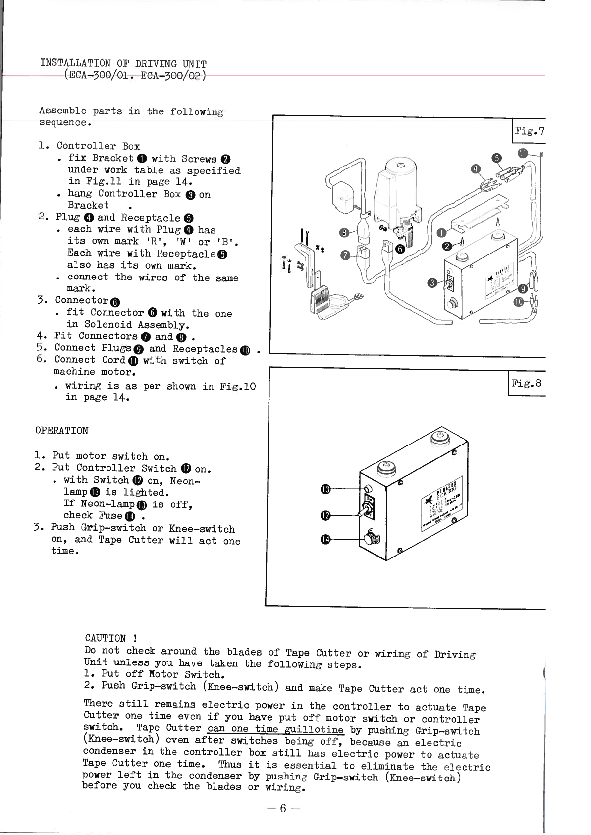
1.
Controller
•
•
2.
PlugQand
•
•
3.
ConnectorO
•
Fit
4.
Connect
5.
6.
Connect
machine
o
0.
fiX
under
in
Fig.l1
hang
Bracket
each
its
Cach
also
connect
mark.
fit
in
Solenoid
Connectors
wiring
in
page
parts
Bracket
worktable
Controller
Receptacieø
wire
own
mark
wire
has
its
the
Connector
PlugsØ
Cord®
motor.
is
14.
in
Box
0
in
with
with
wires
Assembly.
0
with
as
per
the
toll
with
as
page
Box
Plug
‘R’,
ReccptacleØ
own
mark.
of
with
0
andØ
and
Receptacles
switch
shown
Screws
specified
14.
0
Q
?T.TI
owin
on
has
or
the
the
fig.
7
@
?
B?.
‘
L_)
/
I
(r4t
L
‘
0
o®i
A
i
H
@
same
one
of
in
Fig.lO
L
Fig.8
OPERATION
1.
Put
motor
2.
Put
Controller
•
with
lamp®
If
check
Push
3.
on,
and
time.
switch
Switch®
is
lighted.
Neon—lamp®
Puse®
Grip—switch
Tape
CAUTION
Do
Unit
1.
2.
There
Cutter
switch.
(Knee—switch)
condenser
Tape
power
before
not
Put
Push
Cutter
Cutter
check
unless
off
Grip—switch
still
one
left
you
Switch
on,
Motor
time
Tape
in
in
check
on.
®
Neon—
off,
is
or
Knee—switch
will
around
you
have
remains
even
Cutter
even
the
one
time.
the
the
on.
act
the
taken
Switch.
(Knee—switch)
electric
if
can
after
controller
Thus
condenser
blades
one
blades
you
one
switches
the
have
box
it
by
or
of
following
power
time
is
pushing
wiring.
Tape
and
put
uil1otine
being
still
essential
make
in
the
off
has
Cutter
steps.
motor
off,
Grip—switch
or
Tape
controller
by
because
electric
to
wiring
Cutter
switch
pushing
power
eliminate
(Knee—switch)
[/:
of
act
to
actuate
or
controller
Grip—switch
electric
an
to
the
Driving
one
actuate
electric
time.
Tape
—6
Page 9

LNSTALLATIUN
—
UI
Dd1V
(tWA—Iou/jo)
INC
UN
I
lease
Cultot
apu
shown
Lssernb]
3equeflce.
or
and
in
Fi.9.
-.
Ass
and
Mount
h
in
in
Mount
in
Fi;.
Solenoid
•
preset
and
(0039”)
•
push
then
0.
•
1ihtly
Machine
Screws
confirm
smoothly
by
•
tighten
Torque:
•
overlap
Stationary
within
when
lowest
overlap
and
down
confirm
properly
by
Cut
Connect
Compressor.
lix
and
position.
piucooC
in
IL
pu
e
asc(mb
coro
b
em
Knee
HiackotO
posi
pauc
BracketO
position
11.
Stationary
hand.
Movable
®
by
hand.
thread
Foot
Presser
the
up
to
e
4—5.
to
iII’,
I
prov
c
Bracket
Switch
tion
as
L4..
as
assembly
the
up
Plun;crØ
en;ae
attach
Arm
9
Rack9
by
Screws
llO—150kt,/cm
of
Movable
Blades
0.5—1.5mm
position.
by
1oosenin
and
moving
hand.
Tape
by
chain
Tube®
Lift
Arm
Luc
item
tOe
ace
jded,
0
9
unuer
specified
under
also
overlap
Rack
(Ritht)
movin
9
Blade
Cutter
movin
with
Lever,
on
t:tLLalion
‘Cut
tollowiriu
So
r
wo
ac
,
Ur
icke
in
one
work
work
specified
of
Movable
Blades
0
by
at
hand,
with
Bracket
with
and
Pinion
F1unerØ
securely.
and
should
(0.020—0.059”)
in
is
Adjust
Nuts®
Rack
0
actuates
Pluner
or
the
Air
Cloth
machine
Ler
,
per
unit.
in
Pinion
9
be
its
the
up
similar.
Plate
in
of
I
is
Nu
shown
9
table
ii
table
1.0mm
and
on
0
and
9
;u
¶Lino
‘/
\
(same
Valve
be
hand.
Switoh
and
1
pushim
by
water
before
oil
in
of
from
lOk:;/cm
2
Nut®
one
adjust
cutting
of
adjust
accumulated.
is
it
to
Container®
Air
Air
or
and
by
turnin
Tape
and
time.
the
as
.
ID
_-/-
11
‘.
in
0
DAILY
1.
2.
Keep
half level.
7.
Loosen
8.
at
Facet®
Push
9.
will
10.
If
oil
per
Cutter.
Turn
,
-
I&
MAINTENANCE
Drain
finler
Drain
line
the
Open
water
when
water
A
oil
machine)
the
pressure
Air
should
Lock
3.5—5.0k;/cm
2
Knee
actuate
necessary,
in
Container®
times
5
Nut®
by
Pin®
reaches
be
used
in
Compressor.
Compressor
below.
0aue
set
Cutter
drop
one
drop
of
Tape
this.
by
the
for
its
of
7
Page 10
©
//
—8--
Page 11

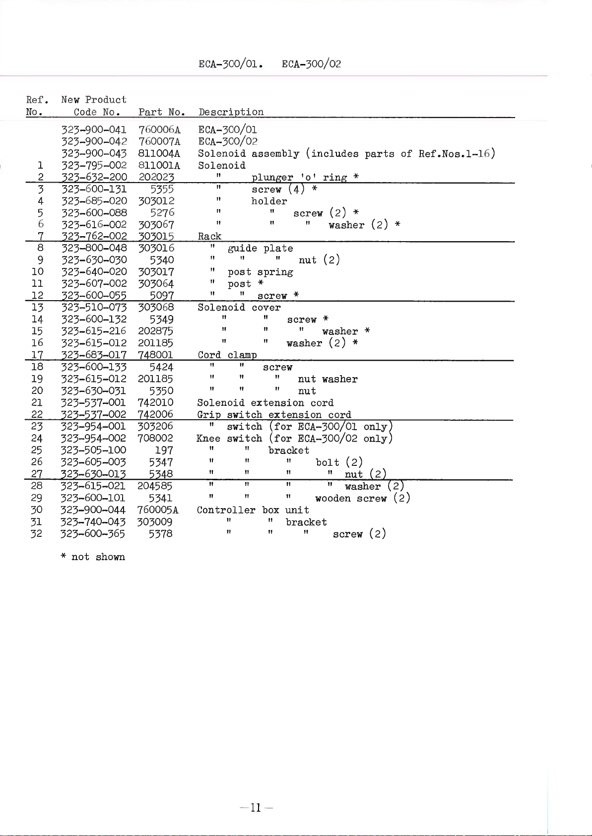
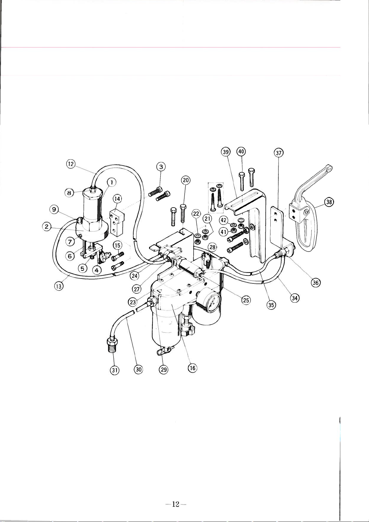
Ref.
No.
10
12
14
15
16
17
18
19
20
21
22
PARTS
TKIJ—520
305169
523—900—038
505007
1
523—.508-.0l2
303002
2
523—873—015
305096
323—640—020
305097
323—633—005
500006
523—875—018
1186 1186
6
525—600—246
500007
523—765—001
5220
323—600—291
503005
525—560-037
1186
323—600—246
503065
523—560—040
1186
TKU—320
303135 500141
525—900—039
305020
525—508—015
305151 300003
323—873—016 325—873—017
303096 303096
325—640—020
303097 303097
323—655—005
303021 300006
525—875—019
525—600—246 525—600—246
300007
323—765—001 323—763—001
5220
523—600—291 523—600—291
505022
523—560-058
1186
323—600—246
305063
525—560—040
1186
525—600—246 523—600—246
503011
523—800—046
1186
523—600—246
303013
523—740—050
5266
323—600—265
5276
525—600—088
503067
523—616—002
305128
523—740—052
5113
323—600—039
5001
323—600—059
503011
523—800—046
1186
323—600—246
503013
523—740—050
5266 5266
523—600—265
5276 5276
323—600—088 323—600—088
305067
525—616—002
303128
525—740—052
5113
323—600—059 523—600—039
5001
523—600—059 523—600—059
5345
325—600—096
*
for
ECA—300/01
325—600—096
LIST
only
FOR
TKU—520,
TKR—530
523—900—040
50000lA
523—508—014
323—740—049
323—640—020
323—655—005
525—875—018
1186
500007
5220
500008
325—560—039
1186
323—600—246
505065
525—560—040
2921
525—600—026
300011
323—800—047
1186
525—600—246
300150
323—740—051
323—600—265
303067
325—616—002
500140
323—740—055
5115
5001
2902
325—600—259
(2)
(2)
(
TKU—520
=
)
AND
Description
Tape
cutter
“
Movable
U
U
Stationary
Pinion
Fabric
Gear
Tape
guard
guard
I?
U
guide
U
Solenoid
I?
Grip—switch
Tape
cutter
quantity
I?
blade
screw
U
bracket
screw
TKR550
head
frame
spring
blade
U
(2)
screw
screw
plate
U
washer
bracket
screw
frame
screw
screw
(2)
complete
bracket
stop
screw
(2)
(2)
*
screw
*
(2)
screw
ring
(2)
(2)
*
(2)
—9
Page 12

r.
10
Page 13
NUA—5oo/ol.
E0A—500/02
Ret’.
No.
10
11
12
13
14
15
16
17
18
19
20
21
22
23
24
25
26
27
28
29
30
51
32
owP[‘edo
N
Cod
525—500—041
525—500—0’1.2
525—500—04
525—755—002
1
2
323—u52—200
323—00—l5l
3
525—(&35—020
4
525—u00—01313
5
6
525—u1D—002
525—7D2—002
7
8
525—800—048
325—650—050
9
325—040—020
323—607—002
525—600—055
525—510—073
323—600—152
323—615—216
323—615—012
525—683.--017
323—600—133
523—615—012
523—630—031
323—537—001
525—557—002
323—954—001
525—954—002
325—505—100
325—605—005
525—650—015
323—615—021
525—600—101
525—900—044
523—740—045
525—600—565
No.
0
PurL
No.
000oA
7
7o000/IL
01100411
131100111
202025
5555
505012
527D
505067
505015
505016
5340
503017
503064
5097
303068
5349
202875
201185
748001
5424
201185
5350
742010
742006
303206
708002
197
5347
5348
204585
5541
76000511
303009
5578
Description
ECA—500/0l
ECA—500/02
Solenoid
Solenoid
Rack
guide
U
I
U
post
post
U U
Solenoid
U
U
Cord
clamp
H
U
U U
U
Solenoid
Grip
switch
switch
Knee
switch
U
U
U U
U
Controller
U
assembly
plunger
screw
holder
plate
spring
*
screw
cover
U
U
screw
extension
bracket
U
box
U
(4)
screw
*
screw
washer
nut
extension
(for
ECA—500/01
(for
ECA—300/02
U
U
unit
bracket
(includes
‘o’
*
nut
U
nut
cord
bolt
wooden
ring
(2)
washer
(2)
*
washer
(2)
washer
cord
U
screw
*
*
*
(2)
nut
washer
screw
parts
(2)
*
only)
only)
(2)
(2)
(2)
of
*
(2)
Ref.Nos.l—16)
*
not
shown
—11
Page 14
©
—12
-
Page 15

—ioo/io
A
hef.
No.
10
11
12
15
14
15
16
17
18
19
20
21
22
23
24
25
26
27
28
29
50
51
32
35
34
55
56
37
58
59
40
41
42
523—’
1
325—u05—OJ
2
523—.uOO—29i
3
4
5
6
7
8
9
—72—001
525—(50—050
525—75—OO’
5_i
3;
525—1
)2)—i)t—014.
525—027—Ol(
525—655—004
523—i59—02/
525—u59—028
325—740—054.
525—600—2u5
325—716—010
523—600—130
323—615—012
523—740—055
523—605—005
325—650—013
323—615—021
323—716—009
323—736—006
323—636—015
525—636—016
325—656—017
523—659—029
525—656—007
523—659—025
525—636—008
323—635—005
325—636—011
323—639—050
325—639—031
323—736—005
323—740—056
325—900—224
523—505—100
523—605—003
523—630—015
525—615—021
l’iodii
odL
0
3
I:
No.
—002
9
)—C:H
—01
1aiI.
513004
2040)4
52)3
20’l
‘0)40
20410
5040
01017
01005
Ol0O(
(01004
600015
(00014
204.615
5266
595002
5425
201185
300215
5547
5548
204585
555001
552001
601020
601026
601002
600012
601011
600005
601014
601012
601013
600015
600016
531001
300216
192
197
5547
5348
204585
Oh
No.
)ocrinLio
Air
1
‘
NIbow
Nipple
P1u
Sleeve
Tubo
rpube
Air
H
II
7
7
H
Elbow
Joint
Valve
Tube
Elbow
Tube
Nipple
Sleeve
P1u
Tube
Tube
Air
Il
Knee
7!
H
H H
H
indor
cy
nuL
support
(2)
(2)
cylinder
reu1ator
actuator
valve
joint
(2)
(2)
valve
H
pad
7
7
holder
2)
screw
‘
bracket
unit
H
H H
H
*
*
bracket
(switch)
bracket
7
7
H
H
I
H
H
screw
screw
screw
screw
1
bracket
H
H
71
H
(2)
nut
I
(2)
(2)
(2)
washer
bolt
(2)
washer
*
*
(2)
(2)
nut
H
(2)
washer
(2)
(2)
*
shown
not
Page 16

I
To
iiac)Lino
1iA1r1’
[cL
To
CCA—00/0j
(SuA—oo/o)
No
La
i
in
b
A5oo/o
flirccLLflc
motor
(IuA—5oo/o;
wi1;ch
)
Prom
Power
Source
Ij.
10
Knee
Bracket
Switch
tO
2
IvIouiiL
for
portion
ECA—500/01(/02)
I
oao
in
work
table
and
ACA—100/lO
Fi.11
30.0
Controller
Box
Bracket
—
Ii
Page 17

Page 18

 Loading...