

Page 1
INSTRUCTION
&
PARTS
CATALOG
WILLCOX
(overlook
UJiL.L*COX £>
11X0
AVENUEOFTHE
>.s:
&
AMERICAS
GIBBS
8t
safety
giBBS.
NEW
YORK.
NEW
500/IV
stitch)
MJQ
inc.
YORK
1001B
ITDl
ESS.79O0
Page 2
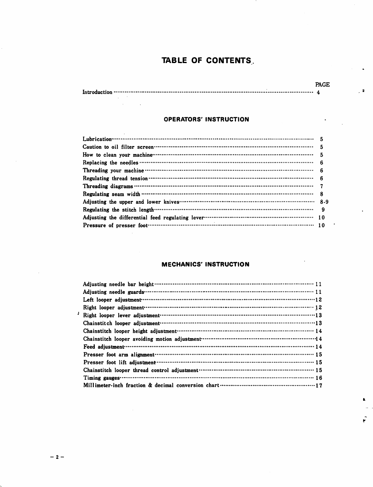
Introduction
TABLE
OF
CONTENTS
PAGE
4
Lubrication
Caution
How to
Replacing
Threading
Regulating
Threading
Regulating
Adjusting
Regulating the
Adjusting
Pressure
Adjusting
Adjusting
Left
to
clean
looper
oil
filter
screen
your
machine 5
the
needles
your
machine 6
thread
tension
diagrams
seam
width 8
the
upper
and
stitch
the
differential
of
presser
needle
needle
bar
guards
foot
height
adjustmen^
Right looper adjustment*
Right
looper
Chainstitch
Chainstitch
lever
looper
looper
adjustment
adjustment
height
OPERATORS'
lower
knives
length 9
feed
regulating
MECHANICS'
adjustment
INSTRUCTION
lever
INSTRUCTION
11
11
12
J2
13
13
14
Chainstitch looper avoiding motion adjustment 14
Feed
adjustment
Presser
Presser
foot
foot
Chainstitch
Timing
Millimeter*inch
gauges
arm
alignment
lift
adjustment
looper
thread
fraction&decimal
control
adjustment
conversion
chart
14
15
5
5
6
6
7
8-9
10
10
15
15
16
17
- 2 -
Page 3

Machine bed frame
(1)
Main
frame and miscellaneous covers''^ -SlS-Sld/IV-
PARTS
LIST
SECTION
503-516/IV'
(2) Main frame and miscellaneous covers 515-516/rV*
(1)
Main
frame and miscellaneous covers -SOS-SH/IV*
(2)
Main
frame and miscellaneous covers 603-514/IV*
Crankshaft
(1)
Needle
(2)
Needle
mechanism
drive
drive
Right looper drive
Left looper drive
(1) Chainstitch
(2) Chainstitch
(1)
Main
and
differential
Main
and
lower
foot
and
lubricating
lubricating
stand
differential
(2)
Upper
and
Presser
(1)
Pump
(2)
Pump
(1)
Attachments
(2)
Attachments
(3)
Attachments
Accessories
Thread
mechanism
mechanism
mechanism
mechanism
looper
drive
looper
drive
knife
mechanism
lift
mechanism
mechanism
mechanism
mechanism
mechanism
feed
mechanism
feed
mechanism
503-516/IV*
503-516AV*
50.3-516/IV"
503-516/IV"
503-516/IV*-
515-516/IV"
515-516/IV-•
503-516/IV-503-516/IV-'
503-516/IV-'
503-516/IV-
503-516/rV-503-516/IV-'
PAGE
20-21
22-23
24-25
26-27
2-8-29
30-31
32-33
34-35
36-37
38-39
40-41
42-43
44-45
46-47
48-49
50-51
52-53
54-55
56-57
58-59
60-61
62-63
64-65
503/IV-44.
504/IV-17.
504/rV-25.
504/IV-47.
504/rV-S-17.
514/IV-20.
514/IV.41.
51,4/IV.S-13.
514/IV-S-18.
Component
515(516)/IV-26.
515(516)/IV-28.
515(516)/IV-31.
515(516)/IV-33.
515(516)/IV-39.
parts
503/IV-48.
504/IV-19.
504/IV-43.
504/IV-S-10.
514/IV-ll.
514/rV-22.
514/IV-42.
514/IV-S-14.
514/IV-S-19.
-
presser
515(516)/IV-27-
515(516)/IV-29515(516)/IV-32-
515(516)/IV-38-
515(516)/IV.51
ORGANIZATION
504/IV-7
504/rV-21""
504/IV-45—•
504/IV-S-16'
514/IV-12-514/rV-23""
514/rV-S-ll'
514/IV-S-15514/IV-S-20-
foot complete*
515(516)/rV-52'
NUMERICAL
INDEX
CHARTS
•503-514/IV-
OF
68
-69
•70
-71
•72
•73
•74
75
76
77
•78
79
80
•81
82
PARTS
Numerical index of new product code numbers with old numbers 83-90
Numerical
Sewing organizations for
W & G
500
index
class
of old
model
numbers
500/IV
with
new
product code
numbers
line 99
specification and summary sheet 100
91-98
- 3 -
Page 4
INTRODUCTION
- 4 -
The new Willcox & Gibbs
Safety stitch
machines.
fast pickupin startingand smooth, quiet
lubricated and
operator, you will appreciate these features helping you to gain more
production with
continue to lead the way in developing new machines that willbenefit
the Operator, achieve more production —with greater ease.
ruggedly
less
500/lV
You
designed
fatigue
is the latest design in Overlock and
will
benefit from its ease of handling,
running.
for trouble-freeperformance.Asthe
as you operate.
It is automatically
Willcox
& Gibbs
will
Page 5
OPERATORS*
INSTRUCTION
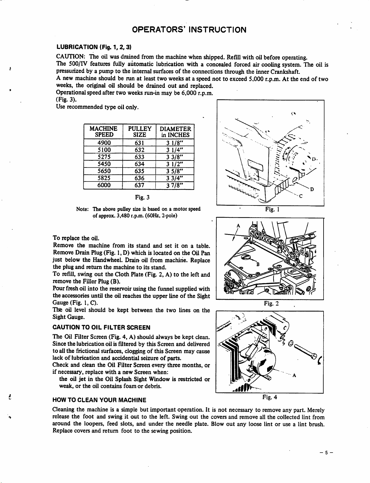
LUBRICATION (Fig.
CAUTION:
The oil
The 500/IV features fully automatic lubrication with a concealed forced air
1,2,3)
was
drained
fromthe
machine
when
shipped.
Refill
withoilbefore operating.
cooling
system. The oil is
pressurizedby a pump to the internal surfaces of the connections through the inner Crankshaft.
A new machine should be run at leasttwo
weeks, the original oil should be drained
weeks
at a speednot to exceed5,000 r.p.m. At the end of two
out
and replaced.
Operationalspeedafter two weeksrun-in may be 6,000 r.p.m.
(Fig. 3).
Use recommended type oil only.
MACfflNE
SPEED
4900
5100
5275
5450
5650
5825
6000
Note: The above pulley size is based on a motor speed
of approx. 3,480 r.p.m. (60Hz, 2-pole)
PULLEY
SIZE
631
632
633
634
635
636
637
Fig. 3
DIAMETER
in
INCHES
3
1/8"
3
1/4"
3
3/8"
3
1/2"
3
5/8"
3
3/4"
3
7/8"
Fig. 1
To
replace
Remove
the
the
oil.
machine
from
its
stand
and
setiton
a table.
Remove Drain Plug (Fig. 1,D) which is located on the Oil Pan
just below the Handwheel. Drain oil from machine. Replace
the
plug
and
return
the
To refill, swing out the
remove
the
Filler Plug (B).
machinetoits
Qoth
Plate (Fig. 2, A) to the left and
stand.
Pour fresh oil into the reservoir using the funnel supplied with
the accessories until the oil reaches the upper lineofthe Sight
Gauge (Fig. I, C).
Tlte oil level should be kept between the two lines on the
Sight Gauge.
CAUTION
The
Since the lubrication oil is filtered by this Screen
to
all
lack
Check and clean
if
necessary, replace
the
weak,orthe
HOW
TO
OIL
FILTER
Oil
Filter
Screen (Fig. 4, A) should always be
the
frictional surfaces, cloggingofthis Screen
of
lubrication and accidential seizureofparts.
the
Oil
withanew
oil
TO
jetinthe
CLEAN
Oil Splash Sight Window is restricted
oil
contains
YOUR
SCREEN
Filter
Screen every three months,
Screen
foamordebris.
MACHINE
when:
and
kept
delivered
may
clean.
cause
or
or
Cleaning the machine is a simple but important operation. It is not necessary to remove any part. Merely
release
around
the
foot
and swingitouttothe left. Swing
the
loopers, feed slots,
and
under
out
the
needle plate. Blow
the covers
and
out
remove all
any
loose lintoruse a
the
collected lint from
lint
brush.
Replace covers and return foot to the sewing position.
- 5 -
Page 6
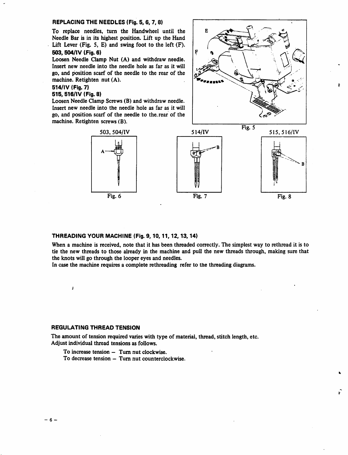
REPLACING THE NEEDLES (Fig.
To
replace needles,
turn
the Handwheel until
Needle Bar is in its highest position.
Lift Lever (Fig. 5, E)
503,504/IV
(Fig. 6)
Loosen Needle Clamp
Insert
new
needle
go,
and
position
machine.
Retighten
and
Nut
into
the
scarfofthe
nut
(A).
swing
(A)
and
needle
needletothe
514/IV (Fig. 7)
515,
516/lV
Loosen
Insert
go,
and
machine.
Needle
new
position
Retighten
(Fig. 8)
needle
Clamp
Screws
into
scarfofthe
screws (B).
503,
the
504/IV
needle
(B)
and
needletothe.
5,6,
7,8)
Liftupthe
foottothe
withdraw
holeasfarasit
left
needle.
rearofthe
withdraw
holeasfarasit
needle.
rearofthe
the
Hand
(F).
will
will
514/IV
Fig. 5
515,
516/IV
Fig. 6
THREADING YOUR MACHINE (Fig.
When a
tie
the
In case
REGULATING
The
Adjust
the
knots
machine
new
will go
the
is received,
threadstothose
through
machine
requires a
THREAD
note
alreadyinthe
the
looper
complete
TENSION
amountoftension required varies with typeofmaterial, thread, stitch length, etc.
individual
To
increase
To
decrease
thread
tensions
tension—Turn
tension-Turn
9,10,11,12,13,14)
that
it has
eyes
and
rethreading
as follows.
nut
clockwise.
nut
counterclockwise.
been
threaded
machine
needles.
Fig.
correctly.
and
pull
refertothe
7
the
new
threading
The
threads
simplest
through,
diagrams.
Fig. 8
waytorethread
making
sure
it is
to
that
- 6 -
Page 7
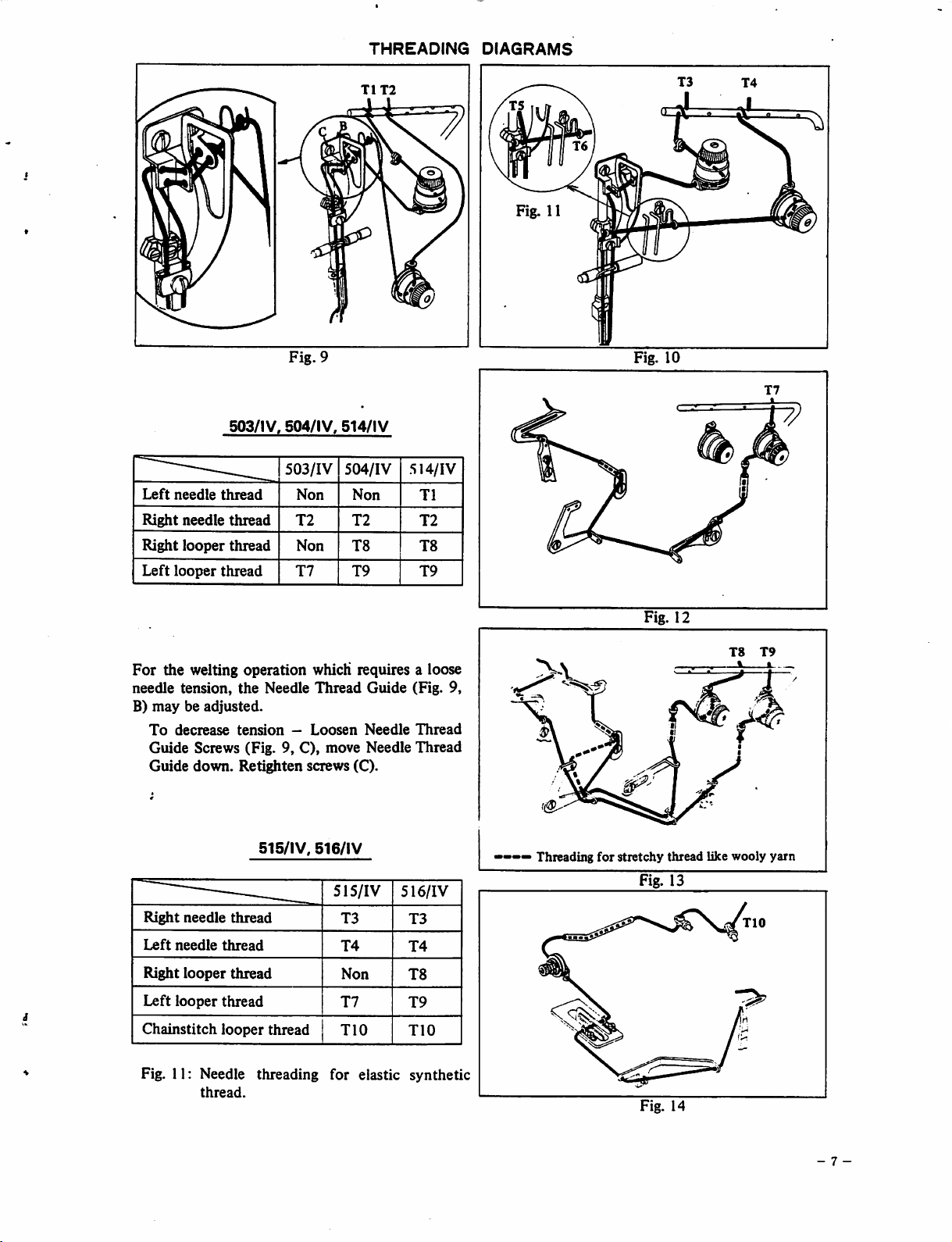
Fig.
THREADING
T1T2
9
DIAGRAMS
Fig.
11
Fig.
10
503/IV,
Left
needle
Right
Right
Left
looper
For
the welting operation which requires a loose
needle
B)
maybeadjusted.
To
decrease
needle
looper
tension,
thread
thread
thread
thread
tension
the
504/IV,
503/IV
Non
T2
Non
T7
Needle
—
Thread
Loosen
514/IV
504/IV
Non
T2
T8
T9 T9
Guide
Needle
Guide Screws (Fig. 9, C), move Needle
Guide
down.
Right
Left
needle
needle
Retighten
515/IV,
-
thread
thread
screws (C).
516/lV
515/IV
T3
T4
514/IV
T1
T2
T8
(Fig. 9,
Thread
Thread
516/IV
T3
T4
Threading
for
Fig. 12
stretchy
Fig. 13
thread
like
T8 T9
wooly
yarn
Right
looper
Left
looper
Chainstitch
thread
thread
looper
thread
Non
T7
TIG
T8
T9
TIG
Fig. 11; Needle threading for elastic synthetic
thread.
Fig. 14
- 7 -
Page 8
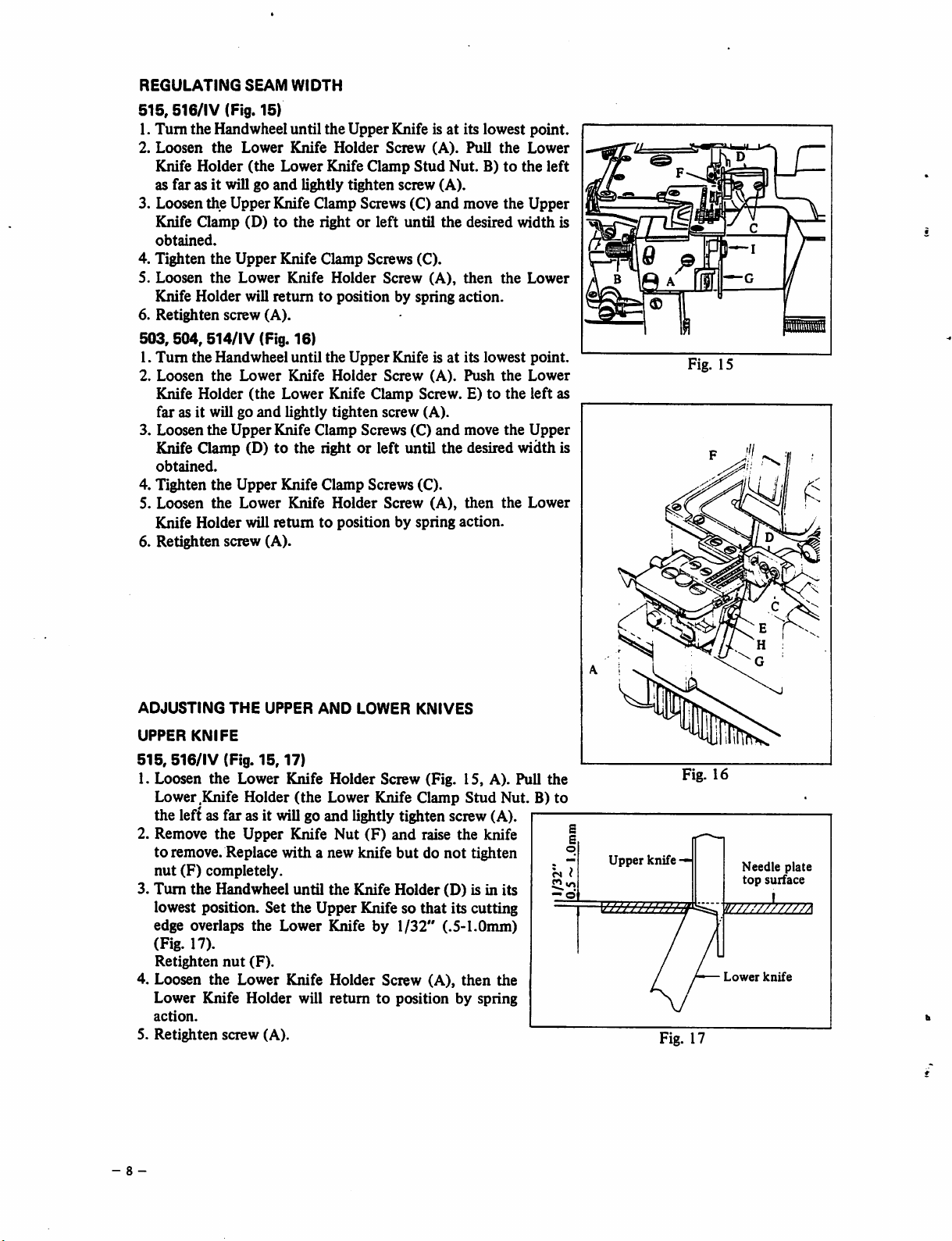
REGULATING
515,516/IV
SEAM
(Fig. 15)
WIDTH
1. Turnthe Handwheel until the UpperKnife is at its lowest point.
2.
Loosen
Knife
as
3. Loosenthe Upper Knife Clamp Screws (C)
Knife
obtained.
4.
Tighten
5. Loosen
Holder
farasit
Qamp
the
will go
the
the
Lower
(the
and
(D)tothe
Upper
Lower
Knife
Lower
lightly
Knife
Knife
Holder
Knife
Screw
Clamp
tighten
rightorleft
Clamp
Screws (C).
Holder
Screw
Stud
screw
until
(A).
Pull
Nut.B)to
(A).
and
move the Upper
the
desired
(A),
then
the
the
Lower
the
width
Lower
left
Knife Holder will returntoposition by spring action.
6.
Retighten
503,504,514/IV
1.
Turn
2.
Loosen
Knife Holder
far
3.
Loosen
Knife
obtained.
4. Tighten
5.
Loosen
Knife
6.
Retighten
screw (A).
the
Handwheel
the
Lower
as it will go
the
Upper
Qamp
the
Upper
the
Lower
Holder
screw (A).
(Fig. 16)
until
the
Upper
(the
and
Knife
Lower
lightly
Knife
Knife isatits
Holder
Screw
(A).
Knife Clamp Screw. E)tothe
tighten
Clamp
screw
Screws
(C)
(A).
and
lowest
Push
move
the
the
point.
Lower
left as
Upper
(D) to the light or left until the desired width is
Knife Clamp Screws (C).
Knife
Holder
will
returntoposition by spring action.
Screw
(A),
then
the
Lower
is
Fig. 15
p •
ADJUSTING
UPPER
515,
516/IV (Fig.
1. Loosen
Lower .Knife Holder
the
left as far as it will go
2. Remove
to remove. Replace with a new knife
nut
(F)
3.
Turn
lowest position. Set the Upper Knife so
edge
(Fig. 17).
Retighten
THE
KNIFE
15,17)
the
Lower Knife
the
Upper
completely.
the
Handwheel until
overlaps
nut
the
(F).
UPPER
(the
Knife
Lower
AND
LOWER
Holder
KNIVES
Screw (Fig. 15, A). Pull
Lower Knife Clamp
and
lightly tighten screw (A).
Nut
(F)
and
raise
butdonot
the
Knife
Holder
that
(^fe
by
1/32"
(.5-1.0mm)
4. Loosen the Lower Knife Holder Screw (A),
Lower
action.
5.
Retighten
Knife
screw
Holder
(A).
will
returntoposition by spring
Stud
Nut. B)
the
knife
tighten
(D) is in its
its cutting
then
the
the
to
?s I
— d
/I
/ ^
s
A i
Fig. 16
s
E
o
Upper
knife
—
!////////
Lower
Needle
top
surface
knife
plate
////A
Fig. 17
- 8 -
Page 9

ADJUSTING
503,504,514/IV
1.
Loosen
Screw.
2. Remove the UpperKnife Screw Nut (F) and raise the knife to remove.
Replace
3.
Turn
Set
the
Retighten
4.
Loosen
spring
5.
Retighten
THE
the
UPPER
(Fig.
Lower
AND
16,17)
Knife
E)to the left asfarasit
withanew
the
Handwheel
Upper
nut
the
action.
screw (A).
Lower
knife
until
Knifesothat
(F).
Knife
LOWER
Holder
Screw
will
butdo not
the
Knife
its
cutting
Holder
Screw
KNIVES
goand
tighten
Holder
edge
(A).
lightly
nut (F)
(D)
(A),
(cont'd)
Push
the
tighten
completely.
isinits
overlaps
then
the
Lower
screw
lowest
the
Lower
Knife
(A).
position.
Lower
Knife
Knifeby1/32"
Holder
Holder
(the
Lower
(.5-1.0mm)
will
returntoposition
Knife
(Fig.
Clamp
17).
by
LOWER
515,
1.
2. Loosen the Clamp Stud Nut (B) and remove the Lower Knife.
3.
4.
5.
503, 504, 514/IV (Fig.
1.
2. Loosen the Lower Knife Clamp Screw (E) and remove the Lower Knife.
3.
4. Loosen the Lower Knife Holder Screw (A), then the Lower Knife Holder will return to position by
5.
Note: A right
4
Knives
the
Upper
grinding.
KNIFE
516/IV
Loosen
Clamp
Insertanew
that the cutting
Loosen-
spring
Retighten
Loosen
Clamp
Insertanew
is
level
spring
Retighten
correct
(Fig. 15, 17)
the
Lower
StudNut. B)to the left as farasit
the
Lower
action.
screw (A).
the
Lower
Screw.
Lower
with the top of the
action.
screw (A).
angled
must be kept sharp. The Lower Knife may be sharpened by use of a grinder whilemakingsure that
angle is
Knife
maybesenttoour
Knife
Lower
Knife
edgeislevel
Knife
16,17)
Knife
Holder
(G)
Holder
Holder
Screw
intothe
with
the topof the
Screw
Screw
E)to the leftas far as it
Knife
(G)
intothe
Upper
Knife
maintained.
Needle
Plate(Fig. 17).Tightenscrew(E).
isalso
distributorsorreturnedtous
(Fig.
will
groove
(A),
(Fig.
will
goand
Lower
available
15,
A).
goand
lightly
of the
Needle
then the
16,A).
tighen
Knife
Clamp
asan auxiliary
Pull
Lower
Plate
Lower
Push
screw
(H),
the
Lower
tighten
Knife
(Fig.
Knife
the
Lower
(A)
setting
sales
for
Knife
screw
Clamp
17).
Holder
(A).
Stud
Tighten
Knife
Holder
will
Holder
(the
(I),
setting
nut
(B).
returntoposition
(the
lightly.
the
blade
sothat
item.
resharpening since it requires special
the
Lower
Lower
cutting
the
Knife
blade
by
Knife
edge
so
REGULATINGTHE STITCH LENGTH (Fig.
To
change
A) and press in the Eccentric Push Rod (B).
sewing direction until the rod drops
Turn
shorter
When desired stitch length isobtained, release the rod (B) and tighten screw (A)
thestitch
the
Handwheel
stitch
Longer
Shorter
(Fig. 19).
Stitch
Stitch
length,
toward
(less
(more
swing
the
stitches
stitches
Cloth
into
desired
per
inch)
per
18,19)
Plate
to the left.
While
the hole in the eccentric.
stitch
lengthasshown
—
Turn
inch)—Turn
Loosen
pressing in on the rod, turn the Handwheel in the
Handwheel
Handwheel
onthe
Feed
Eccentric
Handwheel
clockwise.
counterclockwise.
Push
and
Rod
cover
Screw
fora
(Fig.
longer
18,
or
- 9 -
Page 10
dr
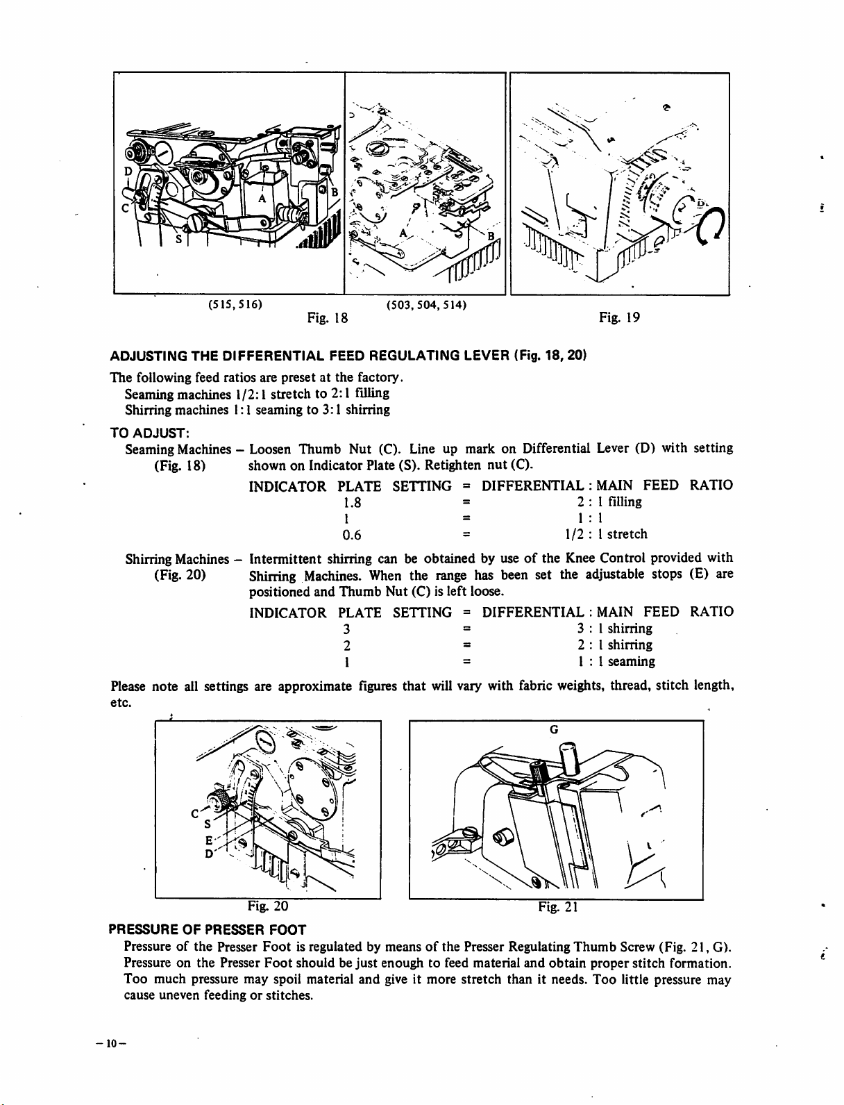
ADJUSTING THE
The
following
feed
(515,516)
DIFFERENTIAL
ratios
are
presetatthe
Fig. 18
FEED REGULATING LEVER (Fig.
(503,504,514)
factory.
18,
Fig. 19
20)
Seamingmachines 1/2:1 stretch to 2:1 filling
Shirring
TO
ADJUST:
machines
1:1
seamingto3:1
shirring
SeamingMachines - Loosen Thumb Nut (C). Line up mark on Differential Lever (D) with setting
(Fig. 18) shown on Indicator Plate (S). Retighten nut (C).
INDICATOR
PLATE
1.8 =
1 =
0.6
SETTING
=
DIFFERENTIAL:
=
2:1
1:1
1/2:1
MAIN
filling
stretch
FEED
RATIO
Shirring Machines - Intermittent shining can be obtained by useofthe Knee Control provided with
(Fig.
20) Shining
positioned
INDICATOR
Machines.
and
When
Thumb
PLATE
3 =
2 =
1 =
the
Nut
(C) is
SETTING
range
left
has
been
set the
loose.
=
DIFFERENTIAL:MAIN
3:1
2:1
1:1
adjustable
shirring
shirring
seaming
stops (E) are
FEED
RATIO
Please note all settings are approximate figures that will vary with fabric weights, thread, stitch length,
etc.
\ /
Fig. 20 Fig. 21
PRESSURE
Pressureofthe
Pressure on
OF
the
PRESSER
Presser
Presser
FOOT
Foot
is regulated by meansofthe Presser Regulating
Foot
should be
just
enough to feed material
Too much pressure may spoil material and give it more stretch than it needs. Too little pressure may
cause
uneven
-10-
feedingorstitches.
and
Thumb
obtain
Screw (Fig. 21, G).
proper
stitch
formation.
Page 11
MECHANICS'
INSTRUCTION
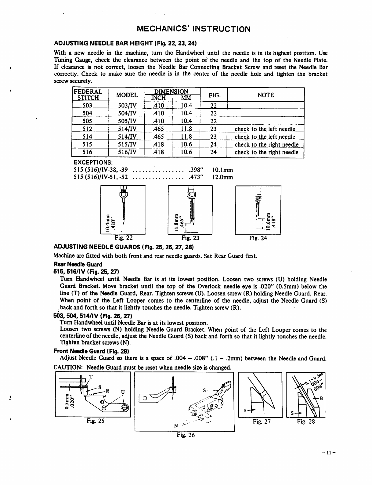
ADJUSTING NEEDLE BAR HEIGHT (Fig.
22,23,24)
With a new needle in the machine, turn the Handwheei until the needle is in its highest position. Use
Timing Gauge, check the clearance between the
If
clearance is
not
correct, loosen
the
Needle Bar Connecting Bracket Screw
correctly. Check to make sure the needle is in the center
screw
securely.
1
FEDERAL
STITCH
503
504
505
512
514
515
516
EXCEPTIONS:
MODEL
503/IV 1 .410 !
504/IV
505/IV
514/IV
514/IV
515/IV
516/IV
DIMENSION
INCH
.410
.410 !
.465
.465 i
.418
.418
515(516)/IV-38,-39
515(516)/IV-51,-52
6
5=
5
d
Fig. 22
ADJUSTING NEEDLE GUARDS (Fig. 25,
26,27,
pointofthe needle
MM
1
10.4
10.4
i
10.4
11.8
11.8
10.6
10.6
1
398'
473'
Fig. 23
28)
of
the needle hole
FIG.
22
22
22
23
23
24
24
10.1mm
12.0mm
and
the
NOTE
checktothe
checktothe
checktothe
checktothe
Fig.
24
topofthe Needle Plate.
and
reset the Needle Bar
and
tighten the bracket
left
needle
left
needle
right
needle
right
needle
Machine are fitted with both front and rear needle guards. Set Rear Guard first.
Rear
Needle
515,516/IV
Guard
(Fig.
25,27)
Turn Handwheei until Needle Bar is at its lowest position. Loosen two screws (U) holding Needle
Guard Bracket. Move bracket until the top
of
line (T)
the Needle Guard, Rear. Tighten screws (U). Loosen screw (R) holding Needle Guard, Rear.
the Overlock needle eye is
.020"
(0.5mm) below the
of
When pointofthe Left Looper comes to the centerlineofthe needle, adjust the Needle Guard (S)
.back
and
forthsothat
503,504,514/IV
(Fig.
it lightly
26,
27)
touches
the
needle.
Tighten
screw
(R).
Turn Handwheei until Needle Bar is at its lowest position.
Loosen two screws (N) holding Needle Guard Bracket.
When
point of the Left Looper comes to the
centerline of the needle, adjust the Needle Guard (S) back and forth so that it lightly touches the needle.
Tighten
bracket
screws (N).
Front Needle Guard (Fig. 28)
Adjust Needle Guard so there is a spaceof.004—.008"
Guard
must
CAUTION: Needle
be reset
when
needle size is changed.
(.1 —
.2mm)
between the Needle
and
Guard.
Fig. 25
Fig.
26
Fig.
27
S-
Fig. 28
11-
Page 12
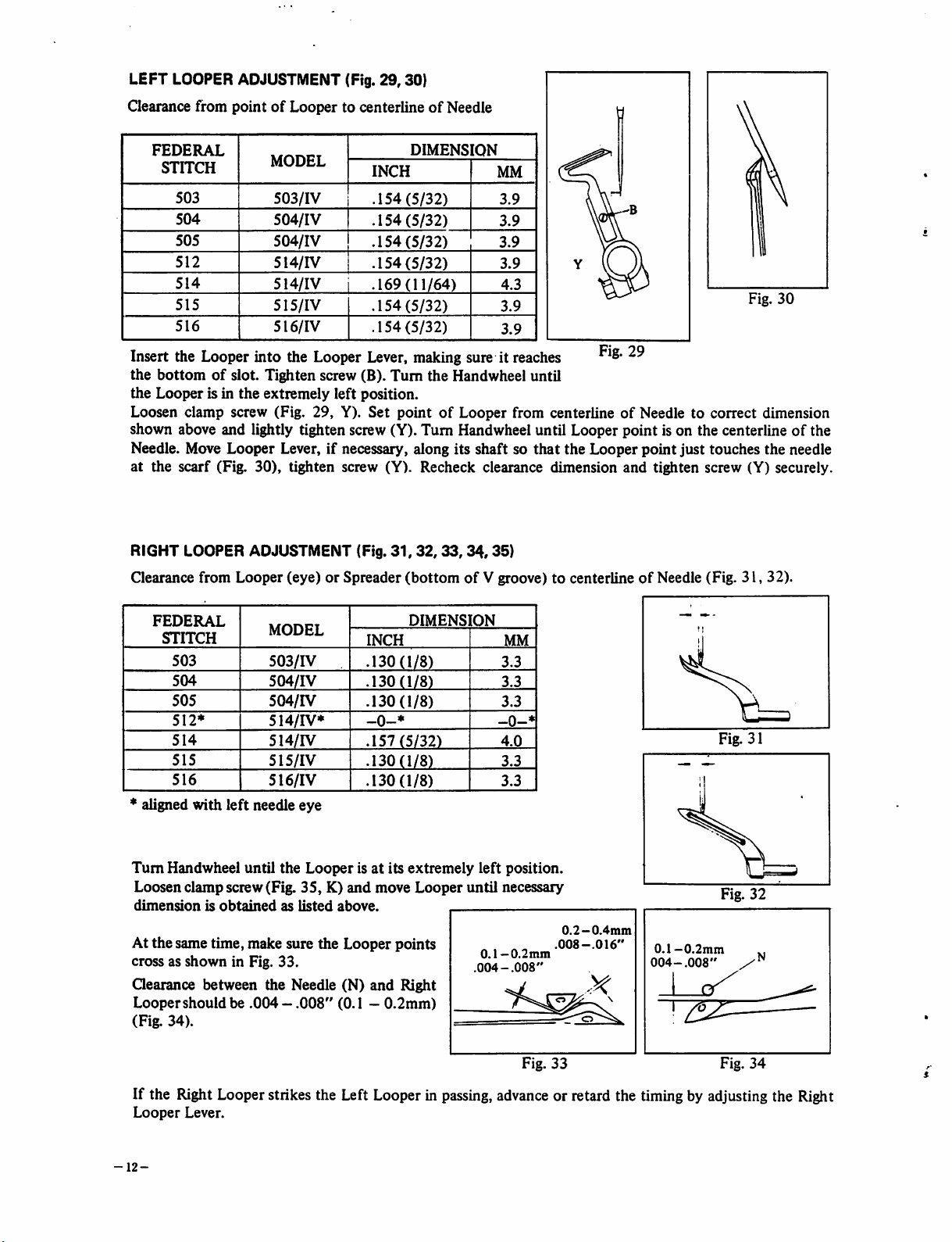
LEFT LOOPER ADJUSTMENT (Fig.
29,30)
Clearance from
FEDERAL
STITCH
503
504
505
512
514
515
516
Insert the Looper into the Looper Lever, making sure it reaches
the
bottomofslot. Tighten screw (B).
pointofLooper to centerlineofNeedle
MODEL
503/IV
504/IV
504/IV
514/IV
514/IV
515/IV
516/IV
DIMENS
INCH
.154
(5/32)
.154
(5/32)
.154
(5/32)
.154(5/32)
.169(11/64)
.154
(5/32)
.154
(5/32)
Turn
[ON
the
Handwheel until
MM
3.9
3.9
3.9
3.9
4.3
3.9
3.9
<1
-B
Y ((
Fig. 29
Fig.
30
the Looper is in the extremely left position.
Loosen clamp screw (Fig. 29, Y).
Set
pointofLooper from centerlineofNeedle to correct dimension
shown above and lightly tighten screw (Y). Turn Handwheel until Looper point is on the centerlineofthe
that
Needle. Move Looper Lever, if necessary, along its shaft so
the Looperpoint just touches the needle
at the scarf (Fig. 30), tighten screw (Y). Recheck clearance dimension and tighten screw (Y) securely.
RIGHT LOOPER ADJUSTMENT (Fig.
Clearance from Looper (eye) or Spreader
31,
32,33,
34,35)
(bottomofV groove) to centerlineofNeedle (Fig.
31,32).
FEDERAL
STITCH
503
504
505
512*
514
515
516
aligned
Turn
with
Handwheel until
Loosenclampscrew(Fig.
dimensionisobtainedaslisted
left
MODEL
503/IV
504/IV
504/rV
514/IV*
514/IV
515/IV
516/IV
needle
the
eye
Looper
35,K)and
is at its
above.
DIMENS]
INCH
.130(1/8)
.130(1/8)
.130(1/8)
-0-*
.157
(5/32)
.130(1/8)
.130(1/8)
extremely
move
Looper
At the same time, make sure the Looper points
cross as
Qearance
Looper
(Fig.
shown
in Fig.
33.
between the Needle (N)
shouldbe.004
34).
—.008"
(0.1 -
and
0.2mm)
Right
(ON
MM
3.3
3.3
3.3
-0-*
4.0
3.3
3.3
left position.
until
necessary
0.1
—0.2mm
.004-.008"
Fig.
0.2—0.4mm
.008-.016"
—
33
0.1
—0.2mm
004-.008"
I
"3^
Fig. 32
Fig.
34
If the Right Looperstrikes the Left Looper in
Looper
-12-
Lever.
passing,
advance
or retard the timingby adjustingthe Right
Page 13
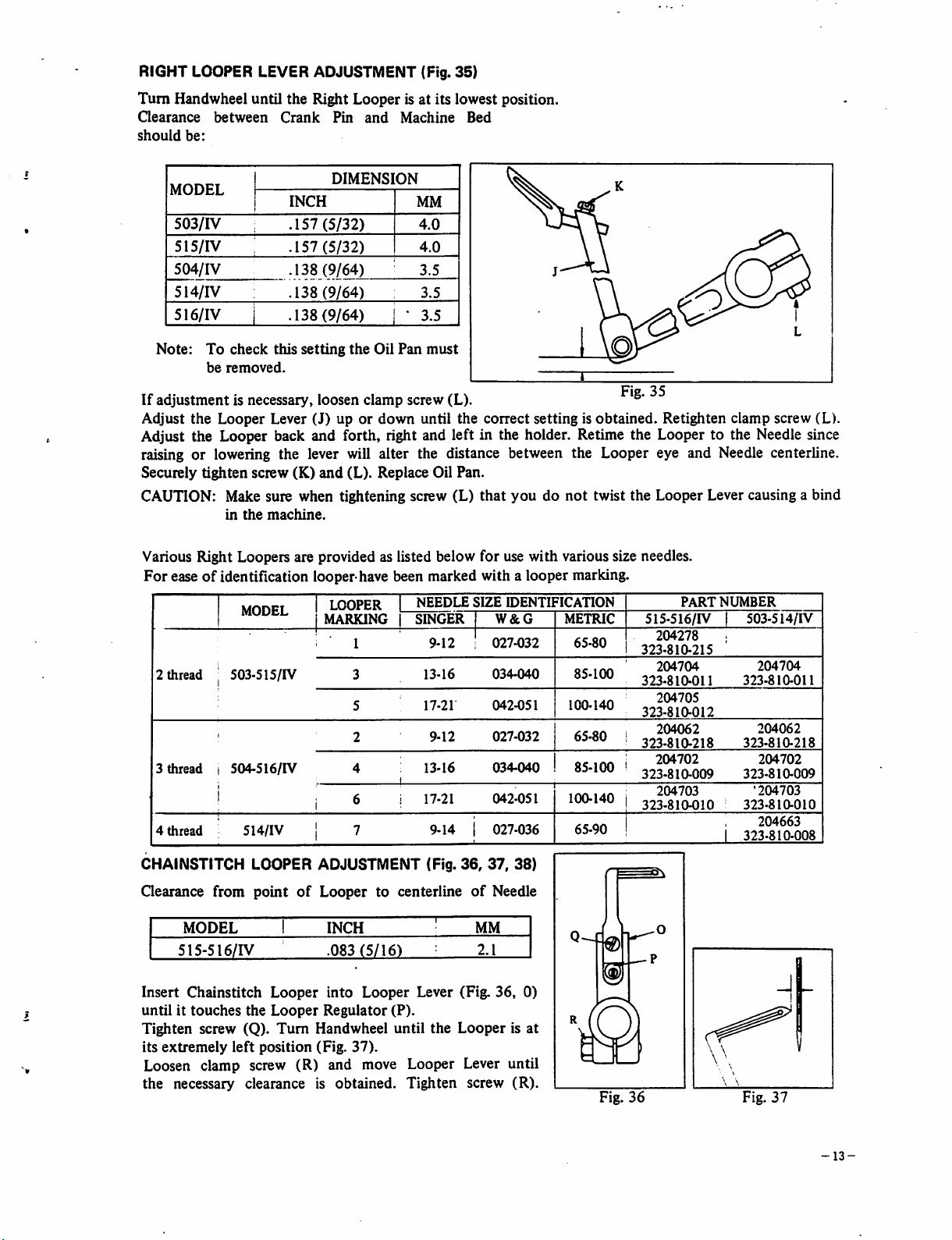
RIGHT LOOPER LEVER ADJUSTMENT (Fig.
Turn
Handwheel until the Right Looper is at its lowest position.
Qearance
should
be:
between
Crank
Pin
and
Machine
35)
Bed
MODEL
503/IV
515/IV
504/IV
514/IV
516/IV
Note:
If
adjustment
Adjust
To
check
be
removed.
is necessary, loosen
the
Looper
INCH
.157
.157
.138
.138
.138
this
Lever
DIMENSl
(5/32)
(5/32)
(9/64)
(9/64)
(9/64)
setting
(J)upor
the
Oil
clamp
down
ON
•
Pan
screw
MM
4.0
4.0
3.5
3.5
3.5
must
(L).
until the
conect
setting is
Fig. 35
obtained.
Retighten clamp screw (L).
Adjust the Looper back and forth, right and left in the holder. Retime the Looper to the Needle since
raising or lowering the lever will alter the distance between the Looper eye and Needle centerline.
Securely tighten screw (K)
CAUTION: Make sure when tightening screw (L)
in
the
machine.
Various Right Loopers are provided as listed below for use with various size needles.
For
easeofidentification looper have been marked with a looper marking.
MODEL
2
3
4
thread
thread
thread
503-515/IV
1
504.516/IV
1
1
5i4/iy
CHAINSTITCH LOOPER ADJUSTMENT (Fig.
and
(L). Replace Oil Pan.
1
LOOPER
1
MARKING
i 1
3
5
2
4
i 6
i 7
NEEDLE
SINGER
9-12
13-16
17-21
9-12
13-16
17-21
9-14
36,
that
SIZE
W&G
027-032
034-040
042-051
027-032
034-040
042-051
027-036
37,
youdonot
IDENTIFICATION
METRIC
65-80
85-100
100-140
65-80
85-100
100-140
65-90
38)
twist the Looper Lever causing a bind
PART
NUMBER
515-516/IV 1
204278
323-810-215
204704
323-810-011
204705
323-810-012
204062
323-810-218
204702
323-810-009
204703
323-8104)10
503-514/IV
323-810-011
323-810-218
323-810-009
•204703
323-810-010
i
323-810-008
i
204704
204062
204702
204663
Qearance
Insert
untilittouches
Tighten screw (Q).
its
extremely
from
MODEL
515-516/IV
Chainstitch
left position (Fig.
point
the
of
Looper
i
Looper
Looper
Turn
Handwheel until
INCH
.083(5/16)
into
Looper
Regulator
37).
to centerlineofNeedle
MM
2.1
Lever (Fig.
36,
0)
(P).
the
Looper
is at
Loosen clamp screw (R) and move Looper Lever until
the necessary clearance is obtained. Tighten screw
(R).
Fig.
36
Fig.
37
-13-
Page 14

CHAINSTITCH LOOPER HEIGHT ADJUSTMENT (Fig. 38)
Turn Handwheel and check the eye to eye relationship
of
the needle and
Looper. The eye of the needle and the eye of the Looper should cross when
the Looper is coming in to the needle and on the way back.Ifthe eye to eye
relationship is
left or right. This adjustment willraise or lower the Loopereye.
not
obtained, adjust the Looper Regulator (Fig. 36, P) to the
The Looper must be set so that the point of the Looper does not quite
touch the needle as it passes. When the above settings are complete, tighten
clamp screw
CHAINSTITCH
To
change
(R)
the
securely.
LOOPER
looper
AVOIDING
avoiding
motion
MOTION
due
to the
ADJUSTMENT
diameter
of the
(Fig.
needle.
39)
are fitted to the machinemake the following adjustment.
Swing
out
Cloth
Plate.
Remove
Avoiding Regulating Screw. (Fig. 39, G).
Less
motion-Turn
More
Check
that the
Retighten
motion-Turn
Looper
screw
screw
Chainstitch
Avoiding
Bedplate.
clockwise.
countei
Needle
Connection
Loosen
This
will
clockwise.
passes
Pin
just
Nut.
Looper
raise
This
behind
Replace
the
Looper
will
the
Bedplate
Avoiding
Avoiding
lower
the
Chainstitch
andCloth
Connection
Looper
When
largerorsmaller
Pin
Connection
Avoiding
Looper
Plate.
Fig.
Nut.
Pin.
Connection
on the
38
needles
Turn
Looper
Pin.
downstroke.
FEED ADJUSTMENT (Fig.
Feed
Dogs have generally been preset at
off. Before adjusting feeds,
cU
Fig.
39
39,
40,
turn
the Handwheel
41)
the
factory with a
until
Standard
needle
across
the
Loosen
feeds
until
Retighten
To
tilt
loosen
turn
screw
Retighten
Woven
Knit
materials —
fronttoback tilt when
the
feeds are at
heightofMain
plateatits
topofthe
Feed
Dog
the
proper
screws (A & B).
the
Feed
Feed
Bar Hinge Pin
(F)
until
screw
(D)
materials
their
highest position.
Feedis0.47"
rearend
Screws
Dogs,
—
tooth.Astraight
feeds (Fig.
(Fig.
heightisobtained
remove
Screw
the
and
Set
Tilt
desired
feeds
tiltisobtained.
replace screws (C & E).
level
feeds higher in
41).
40,
Plug
(3/64)
A & B)
Screw
(D).
the
machine was sewn
1.2mm above
edge
canbeplaced
and
raiseorlower
(Fig.
41).
(Fig.
Remove
the
front
screw
than
the
39,C)and
(E)
and
the
rear
Fig.
40
-14-
Fig. 41
Page 15
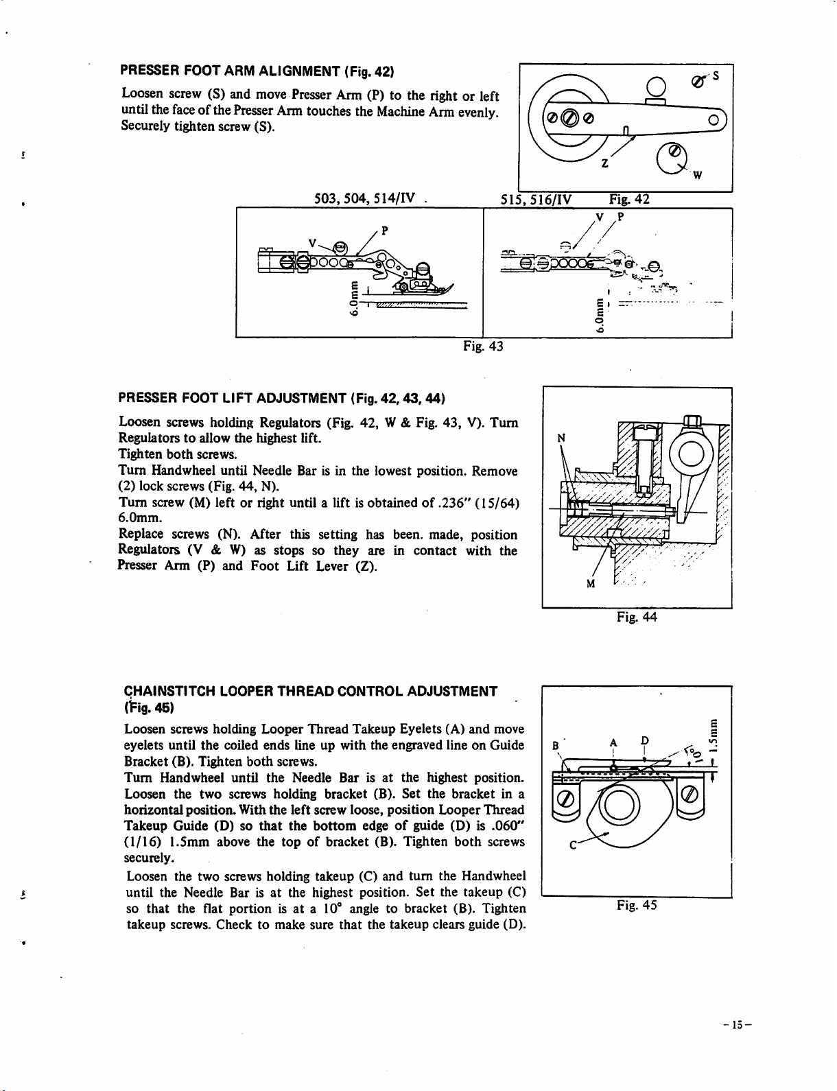
PRESSER
Loosen
untilthe
FOOT
screw
face
(S) and
ofthe
ARM
ALIGNMENT
move
Presser
Securely tighten screw (S).
Presser
Arm
Arm
touches
(Fig.42)
(?) to the right or left
the
Machine
Arm
evenly.
503,504,
PRESSER FOOT LIFT ADJUSTMENT (Fig.
514/IV
42,43,
.
44)
515,516/IV
Fig. 43
Loosen screws holding Regulators (Fig. 42, W& Fig. 43, V)- Turn
Regulatorstoallow
Tighten
Turn
(2)
Turn
6.0mm.
both
Handwheel until Needle Bar is in the lowest position. Remove
lock
screws (Fig.
screw (M)
the
highest lift.
screws.
44,
N).
leftorright until a lift is
obtainedof.236"
(15/64)
Replace screws (N). After this setting has been, made, position
Regulators (V & W) as stops so they are in contact with the
Presser Arm (P) and
Foot
Lift Lever (Z).
Fig.
42
.V
,P
Ss**-
fc.
- Z
CHAINSTITCH
(^ig.
45)
Loosen
eyelets
Bracket
Turn
Loosen
horizontal
Takeup
(1/16)
securely.
screws
until
(B).
Handwheel
the
position.
Guide
1.5mm
Loosen the
until
the
Needle Bar isatthe highest position.
so
that
the flat
takeup
screws.
LOOPER
holding
the
coiled
Tighten
two
both
until
screws
With
(D) so
above
two
screws holding
portion
Checktomake
THREAD
Looper
ends
line up
screws.
the
Needle
holding
the
left
that
the
the
topofbracket
Thread
bracket
screw
bottom
takeup
CONTROL
Takeup
with
Bar
is at
loose,
ADJUSTMENT
Eyelets
the
engraved lineonGuide
the
(B).
Set
position
edgeofguide (D) is
(B). Tighten
(C)
and
turn
Set
(A)
and
highest position.
the
bracket
Looper
both
the Handwheel
the
takeup
is at a 10° angle to bracket (B). Tighten
sure
that
the
takeup
clears
guide
move
in a
Thread
.060"
screws
(C)
(D).
Fig.
Fig.
44
45
-15
—
Page 16
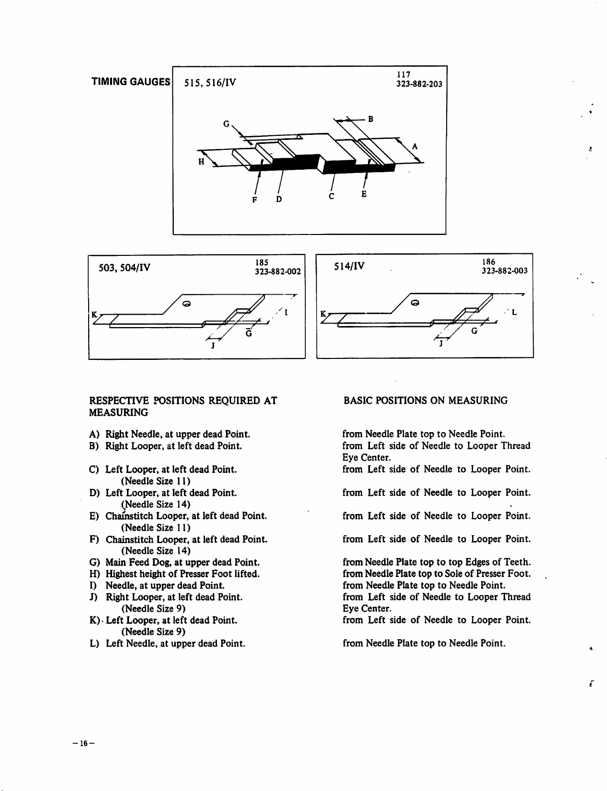
TIMING
GAUGES
515,
516/IV
117
323-882-203
B
\^A
F D
503,
504/IV
RESPECTIVE
MEASURING
POSITIONS
A) Right Needle,atupper
B)
Right
Looper,atleft
C) Left Looper, at
(Needle
D)
Left
Looper,atleft
(Needle
E)
Chamstitch
(Needle
left
dead
Size
11)
dead
Size
14)
Looper,atleft
Size
11)
J
REQUIRED
dead
dead
Point.
Point.
Point.
dead
Point.
185
323-882-002
Point.
F) Chainstitch Looper,atleft dead Point.
(Needle
G) Main
H) Highest heightofPresser
I)
Needle,atupper
J) Right Looper, at
(Needle
K) •
Left
(Needle
L)
Left
Needle,atupper
Size
14)
Feed
Dog,atupper
dead
Size
9)
Looper,atleft
Size
9)
left
Point.
dead
dead
dead
dead
Foot
Point.
Point.
Point.
Point.
lifted.
AT
C
514/IV
BASIC
from
from
Eye
from
from
from
from
from
from
from
from
Eye
from
from
E
Center.
Center.
POSITIONS
Needle Plate
Left
sideofNeedletoLooper
Left
sideofNeedletoLooper
Left
sideofNeedletoLooper
Left
sideofNeedletoLooper
Left
sideofNeedletoLooper
Needle
Needle
Plate
Plate
Needle
Needle
Plate
Left
sideofNeedletoLooper
Left
sideofNeedletoLooper
Plate
ON
toptoNeedle
toptotop
toptoSoleofPresser
toptoNeedle
toptoNeedle
323-882-003
MEASURING
Point,
Thread
Point.
Point.
Point.
Point.
EdgesofTeeth,
Foot,
Point,
Thread
Point,
Point.
-16-
Page 17
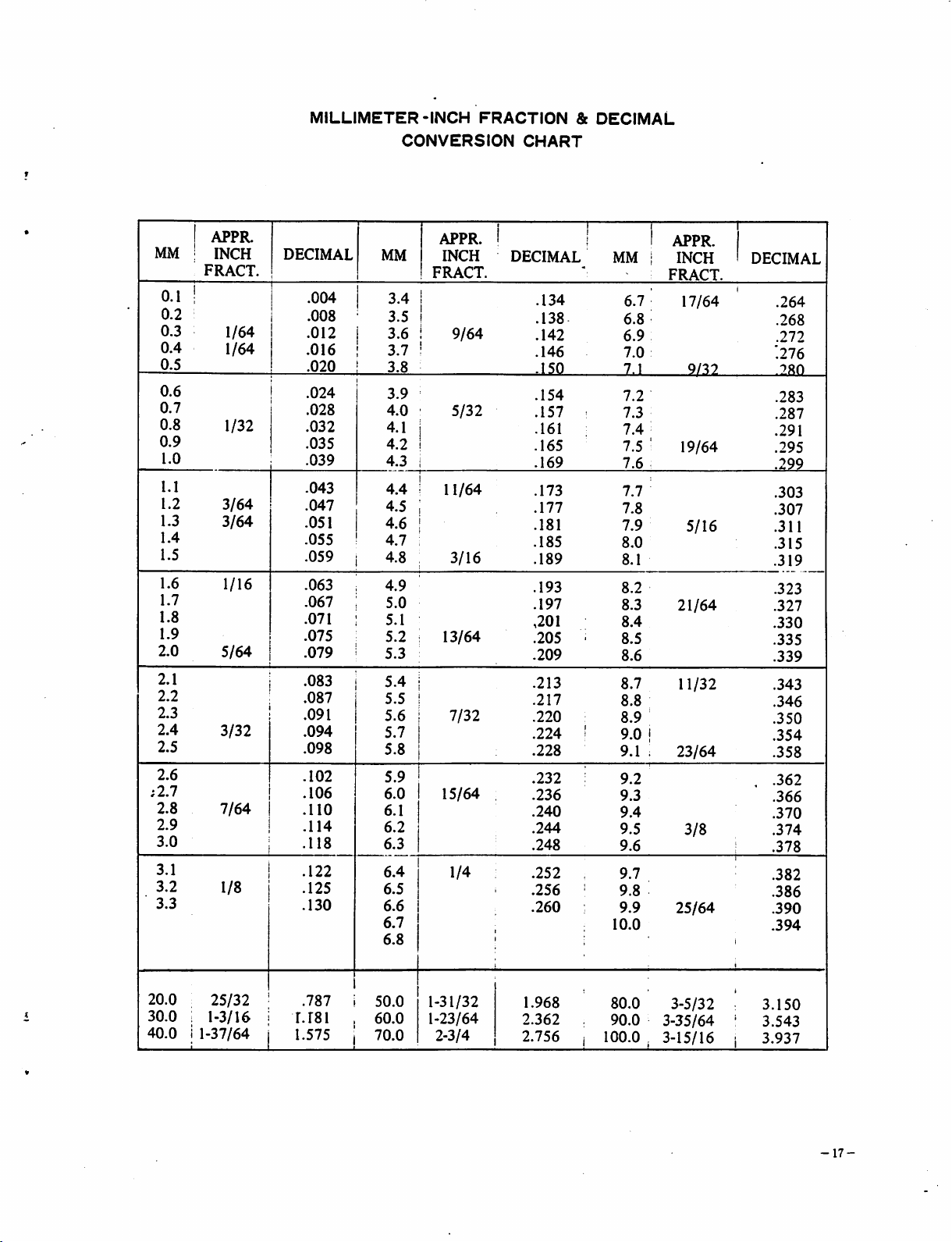
MILLIMETER-INCH
CONVERSION
FRACTION
CHART
&
DECIMAL
MM
2.0
2.1
2.2
2.3
2.4
2.5
2.6
;2.7
2.8
2.9
3.0
3.1
3.2
3.3
0.1
0.2
0.3
0.4
0.5
0.6
0.7
0.8
0.9
I.O
1.1
1.2
1.3
1.4
1.5
1.6
1.7
1.8
1.9
APPR.
:
INCH
FRACT.
I
1/64
1/64
1/32
3/64
3/64
1/16
5/64
3/32
7/64
1/8
DECIMAL
.004
.008
.012
.016
.020
.024
.028
.032
.035
.039
.043
.047
.051
.055
.059
.063
.067
.071
.075
.079
.083
.087
.091
.094
.098
.102
.106
.110
.114
.118
.122
.125
.130
1 • ' 1
5/32
3/16
1 1
DECIMAL
.134
.138
.142
.146
.150
.154
.157
.161
.165
.169
.173
.177
.181
.185
.189
.193
.197
,201
.205
.209
.213
.217
.220
.224
.228
.232
.236
.240
.244
.248
.252
.256
.260
APPR.
MM
3.4
3.5
i
3.6
!
3.7
i
3.8
3.9
4.0
4.1
4.2
4.3
4.4
4.5
4.6
4.7
4.8
4.9
5.0
5.1
5.2
5.3
5.4
5.5
5.6
5.7
5.8
5.9
6.0
6.1
6.2
6.3
6.4
6.5
6.6
6.7
6.8
INCH
FRACT.
i
!
1
1
i
i 9/64
1
11/64
-
13/64
7/32
15/64
1/4
1
i
'
MM i
6.7
6.8
6.9
7.0
7.1
7.2
7.3
7.4
7.5 '
7.6
7.7
7.8
7.9
8.0
8.1
8.2
8.3
8.4
8.5
8.6
8.7
8.8
8.9
9.0
9.1
9.2
9.3
9.4
9.5
9.6
9.7
9.8
9.9
10.0
1
•
i
APPR.
INCH
FRACT.
17/64
9/37
19/64
5/16
21/64
11/32
23/64
3/8
25/64
.
DECIMAL
.
!
.264
.268
.272
'.276
780
.283
.287
.291
.295
.299
.303
.307
.311
.315
.319
.323
.327
.330
.335
.339
.343
.346
.350
.354
.358
.362
.366
.370
.374
.378
.382
.386
.390
.394
20.0
30.0
40.0
25/32
1-3/16
1-37/64
1
.787
1.181
1.575 j
50.0
60.0
70.0
1-31/32
1-23/64
2-3/4
1.968
2.362
2.756 i
.
80.0
90.0
100.0
3-5/32
3-35/64
3-15/16 i
•"
3.150
3.543
3.937
-17-
Page 18
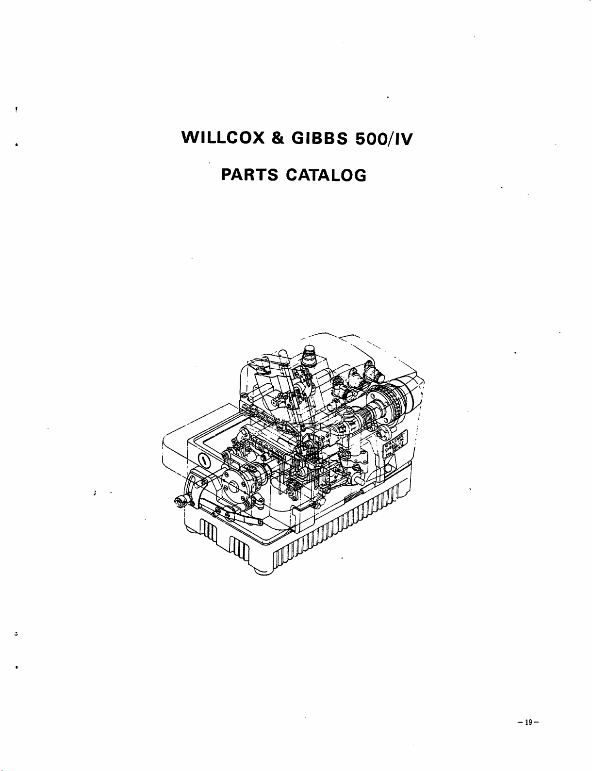
WILLCOX
&
GIBBS
500/IV
PARTS
CATALOG
mm
-
19-
Page 19
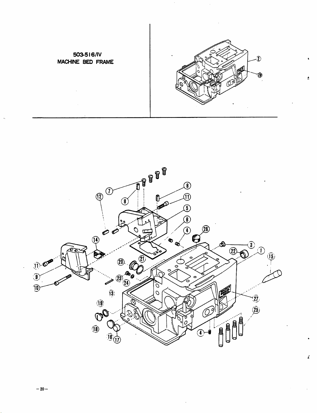
503-516/IV
MACHINE
BED
FRAME
(23T
i®
-20-
Page 20
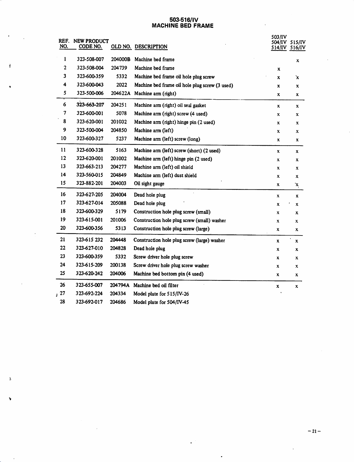
MACHINE
503-516/IV
BED
FRAME
REF.
NO.
3
4
5
6
7
8
9
10
11
12
13
14
15
16
17
18
19
20
NEW
1
2
PRODUCT
CODE
NO.
323-508-007
323-508-004
323-600-359
323-600-043
323-500-006
3^663-207
323-600-001
323-620-001
323-500-004
323-600-327
323-600-328
323-620-001
323-663-213
323-560-015
323-882-201
323-627-205
323-627-014
323-600-329
323-615-001
323-600-356
OLD
204000B
204739
5332
2022
204622A
204251
5078
201002
204850
5237
5163
201002
204277
204849
204003
204004
205088
5179
201006
5313
NO.
DESCRIPTION
Machine
Machine
Machine
Machine
bed
frame
bed
frame
bed frame oil hole plugscrew
bed
frame
oilholeplug
Machinearm (right)
Machine
Machine
Machine
Machine
Machine
arm(right) oil sealgasket
arm(right) screw(4 used)
arm(right) hingepin (2 used)
arm
(left)
arm(left) screw(long)
Machinearm (left) screw (short) (2 used)
Machine
arm(left) hinge pin (2 used)
Machinearm (left) oil shield
Machinearm (left) dust shield
Oilsight gauge
Deadhole plug
Dead hole plug
Constructionhole plugscrew(small)
Construction hole plugscrew(small) washer
Construction hole plugscrew(large)
screw
(3 used)
503/IV
504/1V
514/IV
X
X x
X X
X X
X X
X X
X
X X
X
X
X X
X X
X
X x
X
X
X
X
X X
5I5/IV
516/IV
X
X
X
X
X
X
* X
X
X
21
323-615
22
323-627-010
23
323-600-359
24
323-615-209
25
323-620-242
26
323-655-007
.
27
323-692-224
28
323-692-017
232
204448
204828
5332
200138
204006
204794A
204334
204686
Construction hole plugscrew(large)washer
Dead hole plug
Screw driver hole plug screw
Screw driver hole plug screw washer
Machine bed bottom pin (4 used)
Machine
bed
oil
filter
Modelplate for 515/IV-26
Model plate for 504/IV-45
X X
X
X X
X X
X
X X
•
X
X
-21-
Page 21
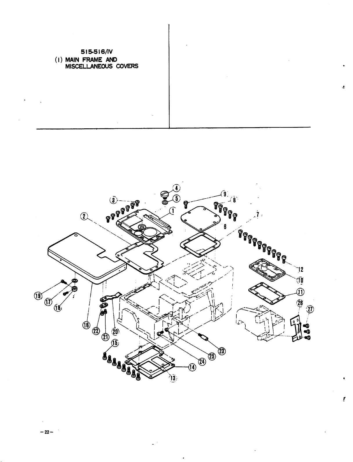
5I5-5I6/IV
(1)
MAIN
FRAME
MISCELLANEOUS
AND
COVERS
J
l
ii
~
-22-
u«&b
'
"••"
lii^^
I
Page 22

REP.
NO.
6
7
8
9
10
11
12
13
14
15
1
2
3
4
5
NEW
PRODUCT
CODE
323-800-032
323-663-010
323-600-014
323-600-354
323-615-229
323-510-247
323-663-208
323-600-0-
323-600-271
323-510-265
323-663-209
323-600-057
323-510-237
323-800-034
323-600-057
NO.
(1) MAIN
OLD
NO.
204842
204851
4009-1
5138B
202287A
204208
204209
5117
2193
20421OA
204211
5117
204212A
204213A
5117
FRAME
DESCRIPTION
AND
MISCELLANEOUS
COVERS
Bedplate
Bedplate gasket
Bedplatescrew (7 used)
Oil filler plugscrew
Oil filler plug screw washer
515-516/IV
Machine
bed
cover
Machine bed cover gasket
Machine
bed coverscrew (round head) (5 used)
Machinebed coverscrew (hex. head)
Machine
Machine
Machine
Machine
arm (right) cover plate
arm (right) cover plate gasket
arm(right) cover plate screw(10 used)
bed
bottom
cover
Machine bed bottom cover plate
Machine bed bottom cover plate screw (8 used)
16
17
18
19
20
21
22
23
24
25
26
27
323-802-210
323-615-201
323-680-001
323-600-013
323-734-204
323-600-068
323-615-015
323-600-314
323-600-011
323-630-001
323-800-222
323-600-014
204215
202576
201139
5084
204218
1216
200162A
5232
5002
3044
204325
4009-1
Cloth plate
Cloth plate hinge stud thrust washer
Cloth plate hinge stud thrust collar
Cloth plate hingestud thrust collar screw (2 used)
Cloth plate lock spring
Cloth plate lock spring screw (2 used)
Cloth plate lock spring screw washer
Cloth plate lock springlatch
Cloth plate stop screw
Cloth plate stop screw nut
Face plate
Face plate screw (3 used)
23-
Page 23
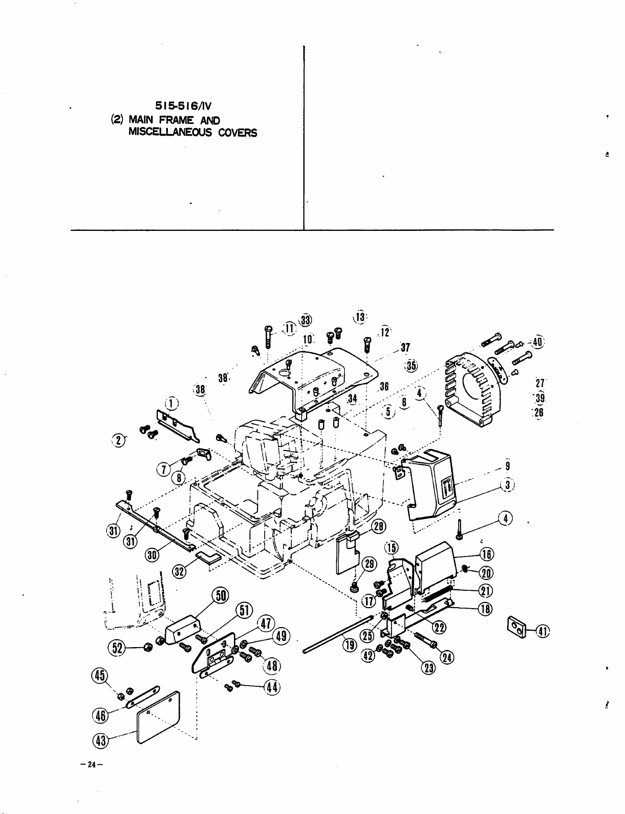
5I5-5I6/IV
(2)
MAIN
FRAME
MISCELLANEOUS COVERS
AND
35)
I--'r
^
l ^
3UC
••;®1
@.
Ml
-24-
®
W
Page 24
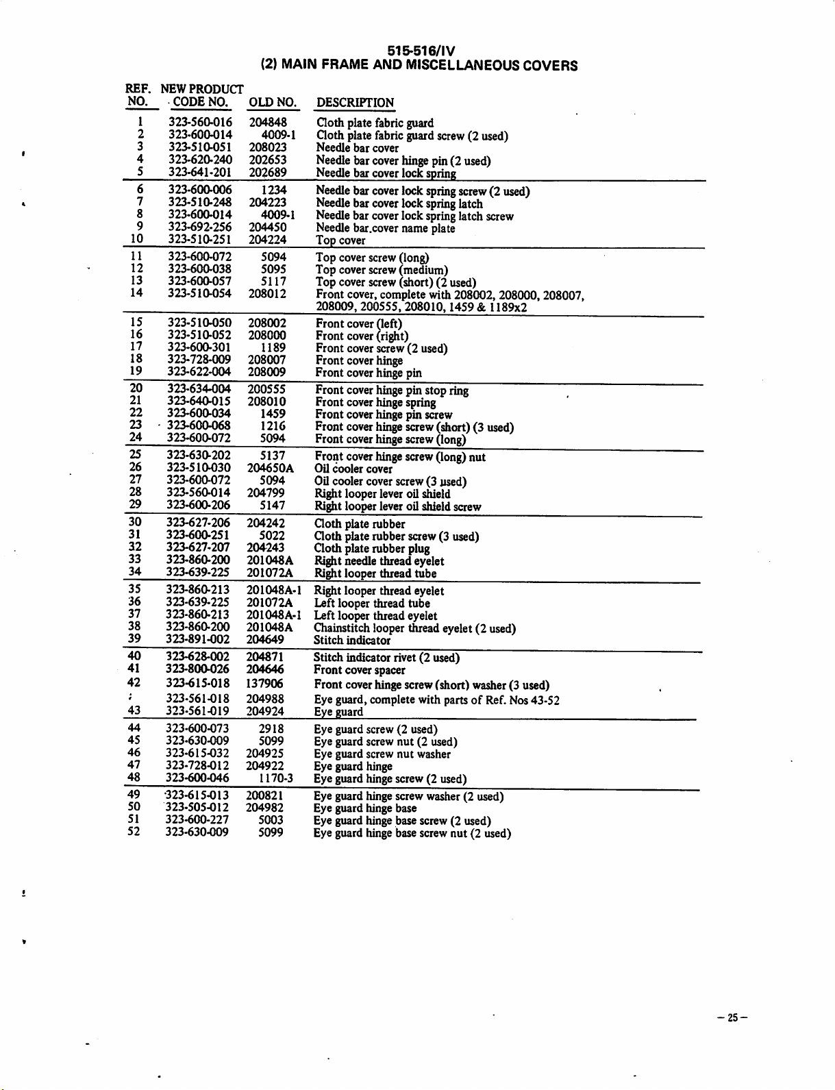
(2) MAIN FRAME AND MISCELLANEOUS COVERS
REP.
NEW
NO. CODE NO.
1
2
3 323-510-051
4
5
6
7
8
9
10
11
12
13
14
PRODUCT
323-S60>016
323>6004)14
323-620-240
323-641-201
323-600-006
323-510-248
323-600-014
323-692-256
323-510-251
OLD
NO. DESCRIPTION
204848 Clothplate
4009-1
208023
202653
202689
1234
204223
4009-1
204450
204224
Clothplate
Needle
bar
Needle
bar
Needle
bar
Needle
bar
Needle
bar
Needle
bar
Needle
bar.cover
Top
cover
323-600-072 5094 Top cover
323-600-038
323-600-057
323-510-054
5095 Top cover
5117 Top
208012
Front
cover
cover,
fabric
fabric
cover
cover
cover
cover
cover
cover
screw
screw
screw
complete
208009,200555, 208010,1459 & 1189x2
15 323-510-050 208002 Front cover(left)
16
323-510-052
17
323-600-301
18
323-728-009
19
323-622-004
20
323-634-004
21
323-640-015
22
323-600-034
23
323-600-068
24
323-600-072
25
323-630-202
26 323-510-030
27
323-600-072
28
323-560-014
29
323-600-206
30
323-627-206
31
323-600-251
32
323-627-207
33
323-860-200
34
323-639-225
35
323-860-213
36
323-639-225
37
323-860-213
38
323-860-200
39
323-891-002
40
323-628-002
41
323-800026
42
323-615-018
4
323-561-018
43
323-561-019
44
323-600-073
45
323-630-009
46
323-615-032
47
323-728-012
48
323-600-046
49
•323-615-013
50
323-505-012
51
323-600-227
52
323-630-009
208000
1189
208007
208009
200555
208010 Front
1459 Front
1216
5094 Front
5137 Front
204650A
5094
204799
5147
204242
Front
cover
Front
cover
Front
cover
Front
cover
Front
cover
cover
cover
Front
cover
cover
cover
Oil cooler cover
CO
cooler
Right
Right
cover
looper
looper
Goth plate
5022 Goth platerubber
204243
201048A
201072A
201048A-1
201072A
201048A-1
201048A
204649
204871
204646
137906
204988
204924
2918
5099
204925
204922
1170-3
200821
204982
5003
5099
Goth platerubberplug
Right
needle
Ri^t
looperthread tube
Rightlooperthreadeyelet
Leftlooperthread tube
Leftlooperthreadeyelet
Giainstitchlooperthreadeyelet(2 used)
Stitch
indicator
Stitch indicator rivet(2 used)
Front cover spacer
Front coverhinge screw(short) washer(3 used)
Eye guard, complete with partsofRef. Nos 43-52
Eye
guard
Eye guard screw (2 used)
Eye guard screw nut (2 used)
Eye guard screw
Eye guard hinge
Eye guard hinge screw (2 used)
Eye guard hinge screw washer (2 used)
Eye guard hinge base
Eye guard hinge base screw (2 used)
Eye guard hinge base screw nut (2 used)
(ri^t)
screw(2used)
hinge
hinge
hinge
hinge
hinge
hinge
hinge
hinge
lever
lever
rubber
threadeyelet
515-516/IV
guard
guard
screw
hinge
pin(2
lock
spring
lock
spring
lock
spring
lock
spring
name
plate
(long)
(medium)
(short)(2 used)
with
pin
pinstop
spring
pin
screw
screw
(short)(3used)
screw
(long)
screw
(long)
screw(3used)
oil
shield
oil
shield
screw(3used)
nut
washer
(2 used)
used)
screw(2used)
latch
latch
screw
208002,
208000, 208007,
ring
nut
screw
-25-
Page 25
(i
)MAIN
COVERS
503-5
FRAME
14/IV
AND
MISCELLANEOUS
MS)
-26-
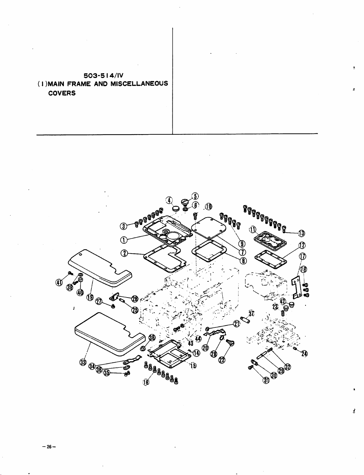
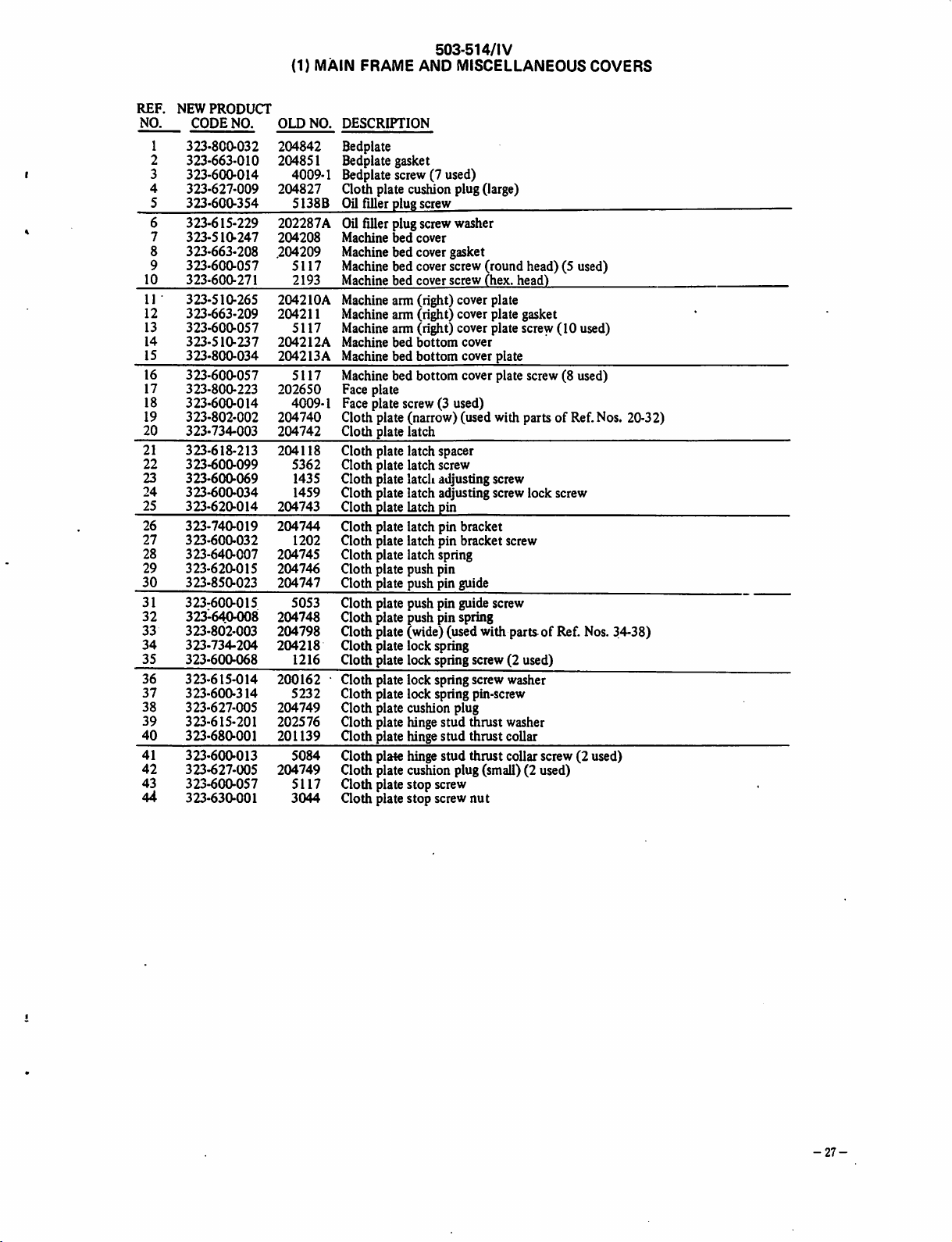
Page 26
503.514/IV
REF.
NO.
3
4
6
8
9
10
11 •
12
13
14
15
1
2
5
7
NEW
PRODUCT
CODE
323-800-032
323-663-010
323-600-014
323-627-009
323-600-354
323-615-229
323-510-247
323-663-208
323-600-057
323-600-271
323-510-265
323-663-209
323-600-057
323-510-237
323-800-034
NO.
(1) MAIN FRAME AND MISCELLANEOUS
OLD
NO.
DESCRIPTION
204842
204851
4009-1
204827
5138B
202287A
204208
.204209
5117
2193
2042lOA
204211
5117
204212A
204213A
Bedplate
Bedplate gasket
Bedplatescrew (7 used)
Cloth plate
OUfiller plug screw
cusMon
plug(large)
Oil filler plug screw washer
Machine
bed
cover
Machine bed cover gasket
Machinebed coverscrew(round head) (5 used)
Machine
bed
cover
screw
(hex.
head)
Machinearm (right) cover plate
Machine aim (right) cover plate gasket
Machine arm (right) cover plate screw (10 used)
Machine
Machine bed
bed
bottom
bottom
cover
cover plate
COVERS
16 323-600-057 5117 Machine bed bottom cover plate screw (8 used)
17 323-800-223 202650 Faceplate
18 323-600-014 4009-1 Face plate screw (3 used)
19 323-802-002 204740
20
323-734-003
204742
Clothpiate(narrow)(usedwithpartsofRef.Nos.
Cloth
plate
latch
21 323-618-213 204118 Cloth plate latch spacer
22 323-600-099 5362 Cloth plate latch screw
23 323-600-069 1435 Cloth plate latcli adjusting screw
24 323-600-034 1459 Cloth plate latch adjusting screw lock screw
25
323-620-014
204743
Cloth
plate
latch
pin
26 323-740-019 204744 Goth plate latch pin bracket
27 323-600-032 1202 Cloth plate latch pin bracket screw
28 323-640-007 204745 Cloth plate latch spring
29 323-620-015 204746 Cloth plate push pin
30 323-850-023 204747 Cloth plate push pin guide
31
32
33
34
35
36
37
38
39
40
323-600-015
323-6404)08
323-802-003
323-734-204
323-600-068
323-615-014
323-600-314
323-627-005
323-615-201
323-680-001
5053
204748
204798
204218
1216
200162
5232
204749
202576
201139
Cloth plate push pin guide screw
Cloth plate push pin spring
Goth
plate (wide) (used with parts of Ref. Nos. 34-38)
Cloth plate lock spring
Cloth plate lock spring screw washer
Cloth plate lock spring pin-screw
Cloth plate cushion plug
Cloth plate hinge stud thrust washer
Cloth plate hinge stud thrustcollar
41 323-600-013 5084 Cloth plate hingestud thrust collar screw (2 used)
42 323-627-005 204749 Cloth plate cushion plug (small) (2 used)
43 323-600-057 5117 Cloth plate stop screw
44
323-630-001
3044 Goth
plate
stop
screw
nut
20-32)
-27-
Page 27
503-514/lV
(2)
MAIN
FRAME
MISCELLANEOUS COVERS
A^
(45
•''
rxo
r^.
.>W\.
^ iK\ ^ Ni\
r>v
J./
• ''-J I
,.;^X-. i
1
<4
;
'•
"'..1
•'
o»
®
1 J
26
-28-
®
Page 28
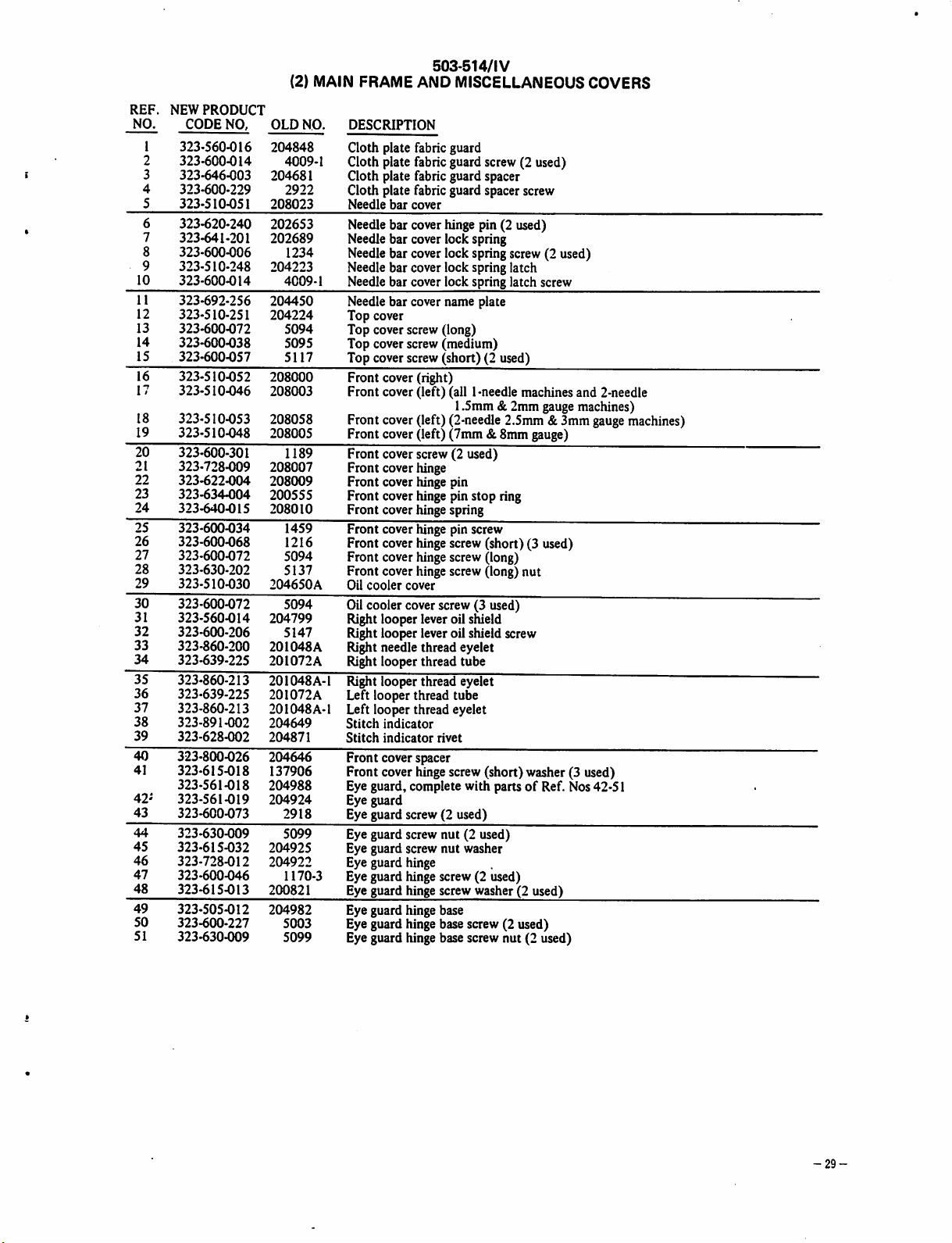
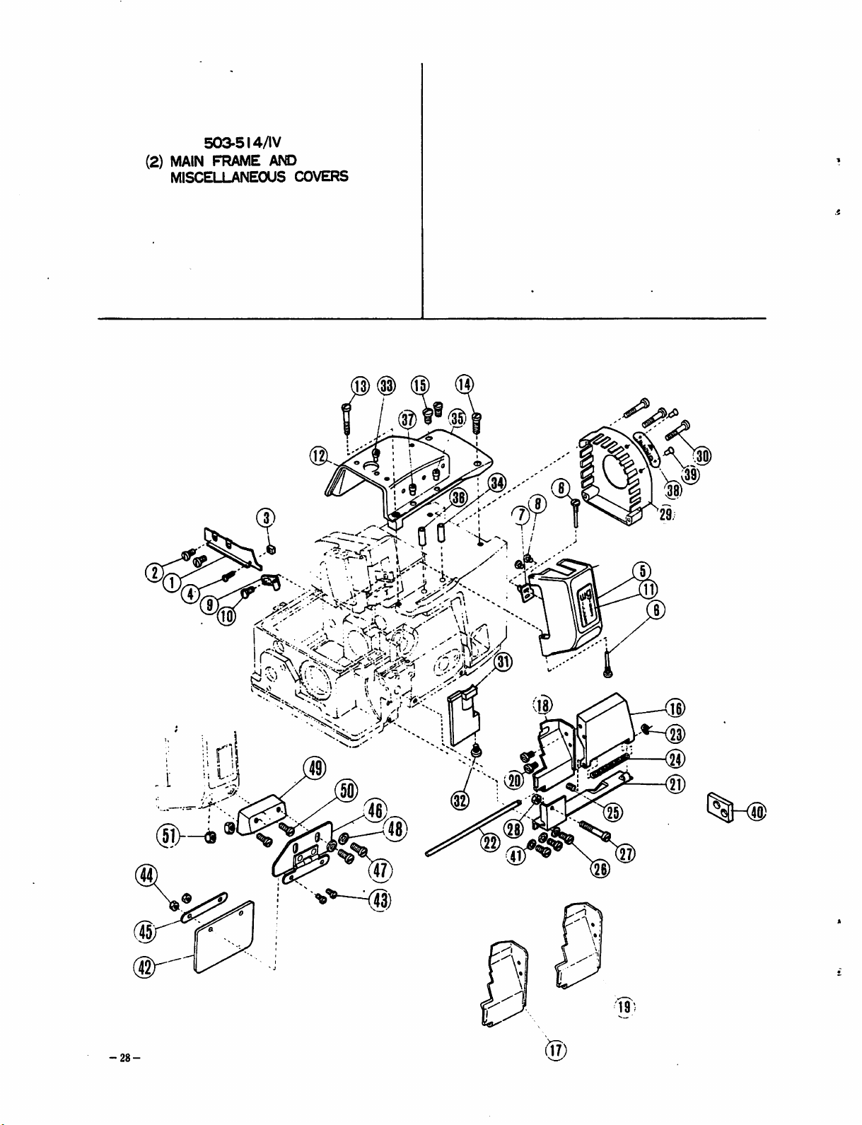
503-514/IV
NEW
REF.
NO.
1
2
3
4
5
PRODUCT
CODE
NO,
323-560-016
323-600-014
323-646-003
323-600-229
323-510-051
OLD
204848
4009-1
204681
2922
208023
6 323-620-240 202653
7
323-641-201
202689
8 323-600-006 1234
9
323-510-248
10 323-600-014
204223
4009-1
11 323-692-256 204450
(2) MAIN FRAME
NO.
DESCRIPTION
Cloth plate fabric guard
Cloth plate fabric guard screw (2 used)
Cloth plate fabric guard spacer
Cloth plate fabric guard spacer screw
Needle
Needle
Needle
Needle
Needle
Needle
Needle
AND
MISCELLANEOUS
bar
cover
barcover
hinge
pin(2 used)
bar coverlock spring
barcoverlock
barcoverlock
spring
spring
bar coverlock springlatch screw
bar covername plate
12 323-510-251 204224 Top cover
13 323-600-072 5094 Topcover screw (long)
14 323-600-038 5095 Top cover screw(medium)
15 323-600-057 5117 Top coverscrew(short) (2 used)
16
17
323-510-052
323-510-046
208000
208003
Front cover (right)
Front cover (left) (all 1-needle machines and 2-needle
1.5mm & 2mm gauge machines)
18
19
323-510-053
323-510-048
208058
208005
Front cover(left) (2-needle2.5mm &3mm
Front cover (left) (7mm & 8mm gauge)
1189 Front cover screw (2 used)
21 323-728-009 208007 Front cover
22 323-622-004 208009 Front cover
23
24
323-634-004
323-640-015
2(K)555
Front
208010 Front cover
cover
hinge
hinge
hinge
hinge
pin
pinstop
spring
ring
25 323-600-034 1459 Front cover hinge pinscrew
26
323-600-068
27
323-600-072
28
323-630-202
29
323-510-030
30
323-600-072
31 323-560-014 204799
32 323-600-206 5147
33 323-860-200
323-639-225
34
35
323-860-213
36
323-639-225
37
323-860-213
38
323-891-002
39
323-628-002
40
323-800-026
41
323-615-018
323-561-018
42^
323-561-019
43
323-600-073
44
323-630-009
45
323-615-032
46
323-728-012
47
323-600-046
48
323-615-013
49
323-505-012
50
323-600-227
51
323-630-009
1216 Front
5094 Front
5137 Front
204650A
5094
201048A
201072A
201048A-1
201072A
201048A-1
204649
204871
204646
137906
204988
204924
2918
5099
204925
204922
1170-3
200821
204982
5003
5099
cover
hinge
screw
cover
hinge
cover
Oil
Oil
Right
Right
Right
Right
cooler
cooler
hinge
cover
cover
looper
lever
looperleveroil shield
needlethreadeyelet
looperthread tube
screw
screw
screw
oilshield
(short)(3
(long)
(long)
(3 used)
Right looper thread eyelet
Left looper thread tube
Left looper thread eyelet
Stitch
indicator
Stitch
Front
indicator
cover spacer
rivet
Front cover hinge screw (short) washer (3 used)
Eye guard, complete with partsofRef. Nos 42-51
Eye guard
Eye guard screw (2 used)
Eye guard screw nut (2 used)
Eye guard screw
nut
washer
Eye guard hinge
Eye guard hinge screw (2 used)
Eye guard hinge screw washer (2 used)
Eye guard hinge base
Eye guard hinge base screw (2 used)
Eye guard hinge base screw nut (2 used)
screw
latch
nut
screw
(2 used)
used)
COVERS
gauge
machines)
-29-
Page 29
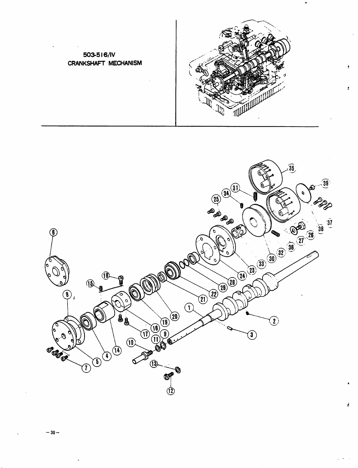
503-516/IV
CRANKSHAFT
MECHANISM
8 .
(12)
-30-
Page 30

503-516/IV
CRANKSHAFT
MECHANISM
REF.
NO.
10
11
12
13
14
15
I6
17
18
19
20
21
22
23
24
25
26
27
28
29
30
31
32
33
1
2
3
4
5
6
7
8
9
34
35
36
37
38
39
NEW
PRODUCT
CODE
323-540-015
323-600-344
323-653-003
323-671-200
323-515-004
323-515-002
323-600-245
323-663-205
323-633-002
323-758-003
323-615-233
323-600-097
323-615-233
323-676-243
323-600-043
323-676-232
323-600-027
323-600-293
323-671-001
323-615-217
323-646-001
323-671-002
323-800-224
323-626-202
323-600-057
323-600-294
323-615-221
323-680-204
323-632-001
323-546-203
323-600-008
323-600-009
323-546-204
323-600-295
323-780-006
323-780-005
323-600-010
323-510245
323-600209
NO.
OLD
204733
5315
202081
204010
204881
204737
5136
-204319
204734
204873
204520
5361
204520
204014
2022
204016
1174
5240
201523A
204018
204019A
204020A
204021
204022
5117
5238
204023
204024
201022
204025
5080
5081
204026
5267
204658
204648
5010
204028
5214
DESCRIPTION
NO.
Crankshaft
Crankshaft oil plug screw
Crankshaft
Crankshaft
oil
wick
bail bearing
Crankshaft ball bearing Geft) housing
Crankshaft ballbearing Geft) housing
Crankshaftball
bearing
Geft)housingscrew(4 used)
Crankshaft ball bearing Geft) housing gasket
Crankshaft ball bearing Geft) retaining ring
Crankshaft
Crankshaft
extension
extension
washer
Crankshaft ball bearing Geft) screw
Crankshaft ball bearing Geft) screw washer
Crankshaft bushing
Crankshaft bushing screw
Crankshaft bushing(center), complete with 1174x2
Crankshaft
bushing
(center)
assembling
Crankshaft bushing(center) screw
Crankshaft ball bearing (center)
Crankshaft ball bearing (center) washer (4 used)
Crankshaft ball bearing (center) spacer
Crankshaft ball bearing (right)
Crankshaft ball bearing (right) plate
Crankshaft ball bearing (right) plate gasket
Crankshaft ball bearing(right) plate screw(4 used)
Crankshaft ball bearing (right) screw
Crankshaft ball bearing (right) screw washer
Crankshaft
Crankshaft oil seal collar
oil
seal
collar
"0"
ring (2 used)
Machine pulley
Machine pulley position screw
Machine pulley screw
Machinepulley collar
Machinepulley collar screw
Machine
Machine
Machine
Machine
Machine
pulleycap —2:1 diff. feed ratio
pulleycap —3:1 diff. feed ratio
pulleycap
screw
(3 used)
pulleycap name plate
pulleycap name plate screw
screw
(2 used)
503/IV
504/IV
514/lV
X
X
X
X
X
X
X
X
X
X
X
X
X
X
X
X
X
X
X
X
X
X
X
X
X
X
X
X
X
X
X
X
X
X
X
X
515/lV
516/IV
X
X
X
X
X
X
X
X
X
X
X
X
X
X
X
X
X
X
X
X
X
X
X
X
X
X
X
X
X
X
X
X
X
X
X
X
-31-
Page 31

(I)
503-516/IV
rCEDLE
DRIVE
MECHANISM
.'-.y
•6^
C-,
ilV
y*'
®
-32-
503-SI4/IV
20)
«b
(JO
Page 32

(1)
NEEDLE
503-516/1V
DRIVE
MECHANISM
REF.
NEW
NO.
1
2
3
4
5
8
9
10
11
12
13
14
15
16
17
18
19
20
21
22
24 *323-561-014 204782
25
26 *323-561-xxx
PRODUCT
CODE
NO.
323-535-205
323-600-296
323-620-237
323-600-297
323-576-004
323-576-005
323-600-040
323-630-005
323-540-232
323-676-233
323-676-028
323-618-006
323-60a013
323-851-213
323-851-222
323-851-215
323-600-014
323-740-023
323-600-228
323-600-302
323-639-019
*323-561-013
323-600-256
OLD
NO.
204029
5233
20271lA
5234
201360A
201441A
5087
Needle
bar
drive
Needle
bar driveconnection capscrew(2 used)
connection
Needlebar driveconnection pin
Needlebar driveconnection pin screw
Needle bar drive crank (right)
(515-516/IV - except
(503-504/IV - except
515-516/IV-51
504/IV-S-10)
Needle bar drivecrank (right)
(514/IV.
Needle
515.516/IV-51
bar
drive
crank(right) clampscrew
&-52.
504/IV-S-10)
&-52)
5181 Needlebar drivecrank (right) clampscrewnut
204031
204032
Needle
bar
drive
Needle
bar driveshaft bushing(left)
shaft
204033A Needlebar driveshaft bushing(right)
201117
5084
Needle
bar
drive
shaft
thrust
collar
Needle
bar driveshaft thrust collarscrew(2 used)
204276 Needle thread guide
202704 Needlethread guide
204046 Needlethread
^ide
wire
4009-1 Needle thread guide wire screw
204783
5061
5227
204657
204781
5029
Needleguard bracket
Needle
guardbracket screw(large)
Needleguard bracket screw (small)
Right looper thread tube (left)
Needleguard (rear), for right needle
Needle
guard(front), for rightneedle
Needle
guard
(front)
Needle
guard(front), forleft needle
screw(2used)
27 323-600-302 5227 Needleguard(front) screw
28
*323-561-xxx
29
323-600-021
30
♦323-561-xxx
31
♦323-561-xxx
32
32^600-021
1206
1206
Needleguard (rear), for left needle
Needleguard (rear) screw
Needle
guard(front) - 503-504/IV
Needleguard (front) - 514/IV
Needle guard (front) screw
33 *323-561-xxx Needleguard (rear) —503-504/IV
Needle
34 *323-561-xxx
35 323-600-021 1206
36 323-740-018 204636
guard(rear) - 514/IV
Needle
guard(rear) screw
Needle
guardbracket
37 323-600-027 1174 Needle guard bracket screw (2 used)
38 323-561-017 204884
39 323-600-245 5136
Movable
Movable
type needleguard —optiond item (514/IV)
type needle guardscrew
40 323-740-037 204762 Edgeguideholder bracket base
4P 323-600-019 1175-3 Edgeguide holder bracket basescrew(2 used)
503/rV
504/IV
514/IV
515/IV
516/IV
X
X
X
X
X
*See Organization
Giart
-33-
Page 33

(2)
503-516/IV
NEEDLE
DRIVE
;i)
MECHANISM
(S)
503-5
'5>—
14/IV
(S)
31! (26
33
\
^
',4^
26
/
27.
(
-34-
-~<V)
Page 34

NEEDLE
REF.
NO.
42 323-604-201 5082A Needlethread tension post
43
44
45
46
47
48
49
«0
51
52
53
54
55
56
57
58
59
NEW
PRODUCT
CODE
NO.
1
2
3
4
5
6
7
8
9
10
11
12
13
14
15
16 323-600-224 9070-2 Needlethread retainer springscrew
17 323-866-214 202706A ^ Needle thread takeup
18 323-600-300 5299 Needle thread takeup screw (2 used)
19 323-851-212 204235 Needle thread guide wire
20
21
22
23 323-600-341 5292 Needle clamp screw (2 used)
24 323-630-213 3119
25
26 323-600-012 1457 Needlebar bushing(upper) screw
27 323-676-263 204627A Needlebar bushing(lower)
28
29
30
31
32
33
34
35
36
37
38
40
41 323-613-001 201482 Needle thread tension disc (2 useo)
323-576-218
323-600-022
323-600-043
323-730-005
323-676-244
323-600-299
323-630-009
323-740-218
323-600-046
323-670-200
323-740-016
323-600-091
323-850-021
323-850-221
323-640-203
♦323-843-xxx
*323-843-xxx
*323-843-xxx
323-676-025
323-600-012
323-653-005
323-686-009
323-638-200
323-686-200
323-600-039
323-510-240
323-600-012
323-900-200
323-630-200
323-676-202
323-780-002
323-800-215
323-900-201
323-642-002
323-851-216
323-600-303
*323-801-xxx
323-600-075
«
*
♦323-801-xxx
323-6004)14
323-649-003
323-600-304
323-7404)17
323-600-098
323-6204)17
323-756-003
323-600-257
•
OLD
no:
202607
2022-4
2022
204628
202609
5154
5099
202610
1170-3
202611
202705A
5359
202495
200041
200205
204625A
1457
202176
204626
201436
201437
5113
202615
1457
202478
201035A
202278
201039
202849
202479
201068
204045
5185
1732
4009-1
204631
5239
204750
5357
204630
204632
5091
DESCRIPTION
Needle
bar
Needle bar drive crank Oeft) screw (with head)
Needle
bar
Needle
bar
Needle bar connecting link bushing (2 used)
Needle bar coimecting link bushing screw (2 used)
Needle bar connecting link bushing screw
Needle
bar
Needle bar
Needle bar connecting bracket bearing
Needle
thread
Needle
thread
Needle thread retainer guide spacer
Needle
thread
Needle thread retainer spring
Needle
bar
Needle
bar
Needle
bar
Needle
clampnut
Needle
bar
Needle
bar
Needle
bar
Needle
bar
Needle
bar
Needle bar bushing oil wick tube clamp
Needle bar bushing oil wick tube clamp screw
Needle bar cap cover
Needle
thread
201037, 201039,
(for
3-thread
Needle
thread
Needle thread tension spring bushing
Needle thread tension spring (heavy)
Needle
threadtension
Needle
thread
Needle
thread
201068,
(for
2-thread
Needle thread tension spring (light)
Top
cover
Top
cover
Needle
plate
Needle plate screw (2
Needle (right)
Needle
(left)
Needle
plate
Needle
plate
Needle
plate
Needle
plate
Needle
plate
Needle plate
Needle plate
Needle
plate
Needle
plate
DRIVE
drive
crank
drive
crank
connecting
connecting
connecting
retainer
retainer
retainer
bushing
bushing
bushing
bushing
bushing oil wick
tension,
201482.x2 &
overlook
tension
tension
tension,
201039,
201482x2&5082A
overlock
thread
guide bar
thread
guide
screw (2
key
key
screw (2
bracket
bracket
bracket
support
support
MECHANISM
(left)
Oeft)
screw
link
(2 used)
bracket
bracket
screw
bracket
bracket
screw
guide
(upper)
(lower)screw
oilwick
oil
wick
clamp
tube
complete
5082A
stitch)
nut
spring
cup
guide
complete
stitch)
bar screw
used)
used)
used)
screw (2
used)
guide pin (2
screw(2used)
(2)
503-516/1V
nut
with
201035A,202278,
with
201035A,
used)
(2 used)
202278,
503/IV
504/IV
514/IV
X
X X
X X
X X.
X x'
X X
X X
X X
X X
X X
X X
X X
X X
X X
X X
X
X X
X X
X X
X X
X
X X
X
X
X
X
X
X
X
X
X
515/lV
516/IV
X
X
X
X
X
X
•See
Organization
Chart
-35-
Page 35

•
RIGHT
503-5
LOOPER
16/IV
DRIVE
MECHANISM
"(i
-36-
Page 36

RIGHT LOOPER DRIVE MECHANISM
503-516/IV
REF. NEW PRODUCT
NO. CODENO. OLD NO. DESCRIPTION
6
7
8
9
10
11
12
13
14
15
16
17
18
19
20
21
22
23
24
25
26
27
28
29
30
31
32
33
34
35
36
37
38
39
40
41
42
43
44
45
46
47
48
49
50
51
52
53
54
55
56
323-730-208
323-600-056
323-620-237
323-600-012
323-730-209
323-576-217
323-600-022
323-620-238
323-600-013
323-615-218
323-600-068
323-540-228
323-618-210
323-600-271
323-617-200
323-676-234
323-626-201
323-676-236
323-676-262
323-632-203
323-525-229
323-630-304
323-600-225
323-617-204
323-620-237
323-600-013
323-530-224
323-851-009
323-653-208
323-653-209
323-6004)41
323-6764)29
323-676-248
323-6004)13
323-515-202
323-627-205
323-600-002
323-676-249
♦
323-81()-xxx
323-600-291
323-900-202
323-630-200
323-676-202
323-642-003
323-780-002
323-613-001
323-604-201
323-800-215
323-866-011
323-600-259
323-866-013
323-600-026
323-615-216
323-851-018
323-600-074
323-851-019
323-600-255
204292
2213-1
2027MA
1457
202709A
204332
2022-4
202712A
5084
202757
1216
204069A Rightlooper levershaft
204311 Rightlooper levershaft thrust washer
2193
202286
204050A
204052A
204081
204437
204438
204055A Rightlooperlevercrank
5239
5286
202045
202711A
5084
204057A
204732
204273
204274
1457-1
204854
204059
5084
204060
204004
1175-2
204061
5220
202480
201035A
202278
201086
201039
201482
5082A
202849
204063A
2902
204902
2921
202875
204905
2905
204903
5012
Ri^t
looper
Right
looper
Ri^t
looper
Right
looper
Ri^t
looper
Right
looper
Ri^t
looper
Right
looper
Right
looper
Right
looper
Right
looper
Ri^t
looper levershaft thrust washerscrew
Ri^t
looper
Right
looper
Right
looperlevershaft
Right
looper
Right
looper
Right
looper
Right
looper
Right
looper
Right
looper
Ri^t
looper
Right
looper
Ri^t
looper
Right
looper
Ri^t
looper
Right
looper
Right
looper
Ri^t
looperleverguide
204059,
5084&204060
Rightlooperlever
Right
looper
Right
looper
Ri^t
looper
Ri^t
looper
Rightlooperleverguide
Ri^t
looper
Ri^t
looper
Ri^t
looper
201086, 201039,
Right
looper
Ri^t
looper
Ri^t
looperthread
Rightlooperthread
Rightlooper thread tension
Ri^t
looperthread tensionpost
Rightlooper thread tensionguide
Ri^t
looper
Ri^t
Right
Right
Ri^t
Ri^t
Ri^t
Looperthread guide
Looper thread guidescrew
thread
looper
thread
looper
thread
looper
thread
looper
thread
looperthread guide
looper thread guide screw
drive
connection
drive
connection
drive
crank
drive
crank
drive
connecting
drive
crank
drive
crank
drive
crank
drive
crank
drive
crank
drive
crank
lever
shaft
thrust
lever
shaft
bushing
bushing
lever
shaft
lever
lever
lever
lever
lever
lever
lever
bushing
shaft
bushing
shaft
bushing
crank
clamp
crank
clamp
crank
clamp
crankpin
crankpin
lever
lever
guide
lever
guide
guide
guide
guide
guide
guide
guide
guide
oil
oil
oil
bushing
bushing
bushing
bushing
bushing
bushing
bushing
lever
lever
lever
lever
lever
lever
screw
thread
tension,
201482x2&5082A
thread
tension
thread
tension
tension
tension
takeup
takeup
takeup
takeup
takeup
cap
screw(2used)
pin
pin
screw
link
screw(2used)
pin
pin
screw
pinthrust
pinthrust
wick
wick
plug
nut
spring
spring
spring
(Use
(large)
(large)
(smaU)
(smaU)
(small)
washer
washer
washer
(front)
(front)
(center)
(rear),
(rear)
screw
screw
screw
screw
(long)
(short)
screw(3used)
(front)
(front)
(front^screw
(front)
(front)
(front)
(rear)
complete
bushing
(middle)
cup
(2 used)
screw
screw
screw
nut
nut
screw
screw
washer
ofl
seal
complete
stop
ring
washer
housing,
housing
housing
housing
with
201035A,
washer
with
204438
complete with
cap
screw(2used)
202278,
503/lV
504/IV
5I4/IV
515/lV
5I6/IV
*See Organization Chart
-37-
Page 37

LEFT
503-516/1V
LOOteR
DRIVE
MECHANISM
-38-
^
II
Page 38

REF.
NO
10
11
12
13
14
15
16
17
18
19
20
1
2
3
4
5
6
7
8
9
NEW
PRODUCT
CODE
323-525-230
323-600-056
323-600-020
323-850-200
323-600-200
323-617-200
323-576-006
323-576-007
323-576-213
323-618-010
323-600-022
323-540-228
323-618-210
323-600-271
323-617-200
323-676-235
323-626-201
323-530-225
323-530-010
323-530-017
NO.
OLD
204047
2213-1
1170-1
201074A
1156
202286
204787
204788
204048A
204789
2022-4
204069A
204311
2193
202286
204054
204052A
204071
204664
204853
503-516/IV
LEFT
DESCRIPTION
NO.
LOOPER
DRIVE
MECHANISM
Left looper drive connection
Left
looper
drive
Left
looper
drive
connection
connection
cap
cap
screw
screw
Left looper driveconnection guide
Left looper driveconnection guidescrew
Left looper driveconnection guidescrewwasher
Left
looper
drive
crank
(503-504/IV—except
Leftlooper
Leftlooper
drive
crank(514/IV.
drive
crank(515-516/IV)
504/IV-S-10)
Left looper drivecrank thrust washer
Leftlooper
drive
crank
screw
(2 used)
Left looper levershaft
Left looper levershaft thrust washer
Left looper levershaft thrust washerscrew
Leftlooperlevershaft thrust washer
Leftlooperlevershaft
Leftlooper
Left looper lever
Left looper lever
Leftlooper
lever
lever
bushing
(2 used)
shaft
bushing
oilseal
- optionalitem,
needle guard ^^204884
(large)(2used)
(small)(2used)
screw
washer
used
with
504/IV-S-lO)
movable
type
503/IV
504/IV
514/IV
X
X
X
X
X
X
X
X
X
X
X
X
X
X
X
515/lV
516/lV
X
X
•X
X
X
X
X
X
X
X
X
X
X
X
X
X
323-600-306
21
323-616-200
22
♦
323-810-xxx
23
323-600-301
24
323-600-019
25
323-900-202
26
323-630-200
27
323-676-202
28
323-642-003
29
323-780-002
30
323-613-001
31
323-604-201
32
323-800-215
33
323-866-012
34
323-600-259
35
323-851-217
36
*See Organization Chart
5284
204293
1189
1175-3
202480
201035A
202278
201086
201039
201482
5082A
202849
204901
2902
193174
Left looper lever clamp screw
Leftlooperleverclamp screwwasher
Left looper
Left looper screw
Left looper screw
Leftlooper
thread
tension,
complete
with
201035A
202278, 201086, 201039, 201482x2 & 5082A
Left looper thread tension nut
Leftlooper thread tensionspringbushing
Leftlooperthread
tension
spring
(middle)
Left looper thread tension spring cup
Left
looper
thread
tension
disc(2used)
Left looper thread tension post
Leftlooper thread tensionguide
Left looper thread takeup
Left looper thread takeup screw
Left looper thread guide wire
X
X
X
X
X
X
X
X
X
X
X
X
X
X
X
X
X
X
X
X
X
X
X
X
X
X
X
X
-39-
Page 39

(1)
CHAIIMSTITCH
MECHANISM
5I5-5I6/IV
LOOPER
DRIVE
r@
••
(11..^©!
13''
^29:
12
/»-
-40-
Page 40

REF.
NO.
3
4
5
6
7
8
9
10
11
12
13
14
15
1
2
NEW
PRODUCT
CODE
323-525-231
323-600-296
323-600-020
323-850-200
323-600-200
323-617-200
323-576-219
323-600-022
323-540-225
323-540-234
323-626-201
323-676-236
323-730-211
323-600-043
323-618-206
NO.
(1) CHAINSTITCH LOOPER DRIVE MECHANISM
515-516/IV
OLD
NO.
DESCRIPTION
204075
5233
1170-1
201074A
1156
202286
204076
2022-4
204079
204080
204052A
204081
204090
2022
204091
Looper driveconnection
Looper
drive
connection capscrew(large)(2 used)
Looper
drive
connectioncapscrew
(small)
Looper driveconnection guide
Looper driveconnection guide screw
Looper driveconnection guide screw washer
Looper drivecrank
Looper drivecrank screw (2 used)
Looper drive shaft
Looper driveshaft bushing(front)
Looper driveshaft bushing(front) oil seal
Looperdriveshaft bushing(rear)
Looper avoidinglink
Looperavoiding link screw(2 used)
Looper
avoiding
link thrust washer(2 used)
(2 used)
16
323-680-206
17
323-600-013
18
323-643-209
19
323-600-271
20
323-615-012
21
323-530-226
22
323-600-306
23
323-616-200
24
♦323-810-217
♦323-810-219
25
323-600-301
i
26
323-716-208
27
323-600-048
28
323-580-208
323-540-233
29
323-600-043
*See Organization Chart
204092
5084
204233
2193
201185
204093
5284
204293
204314A
204431
1189
204172
1333
204077
204078
2022
Looper avoiding link collar
Looper
Looper
avoiding
avoiding
link collar screw(2 used)
link spring(2 used)
Looper avoidinglink spring screw
Looper avoidinglink spring screw washer
Looper lever
Looper lever clamp screw
Looper lever clamp screw washer
Looper,for 2&3mm needle
Looper, for 5mm needle
gauge
gauge
Looperscrew
Looper regulator
Looper regulator screw
Looper
drive
eccentric, complete with 204078
Looper drive eccentric pin
Looper driveeccentric screw (2 used)
-41-
Page 41

(2)
CHAINSTITCH
MECHANISM
5I5-5I6/1V
LOOPER
...
DRIVE
•0.
W
-42-
Page 42

(2) CHAINSTITCH LOOPER DRIVE
REF.
NEW
NO. CODE NO. OLD NO. DESCRIPTION
1
2
3
4
5
6
7
8
9
10
11
12
13
14
15
16
17
18
19
20
21
22
23
24
25
26
27
•28
29
30
PRODUCT
323-525-239
323-620-253
323-615-233
323-630-001
323-618-211
323-617-200
323-600-358
323-625-201
323-600-229
323-672-200
323-576-225
323-600-801
323-540-024
323-676-038
323-676-250
323-618-003
323-600-013
323-680-205'
323-600-305
323-630-015
323-642-201
323-613-001
323-604-229
323-800-215
323-866-213
323-600-341
323-850-246
323-740032
323-600-014
323-600-039
204082A
204519
204520
3044
204115
202286
5333
204518
2922
204084
204517
5381
204874
204875
204089
201056
5084
204087
5224
3056
167077
201482
167072
202849
204095A
5292
204096
204097A
4009-1
5113
Looperavoiding connection
Looper
avoiding
Looper
avoiding
Looper
avoiding
Looper
avoiding
Looper
avoiding
Looperavoidingregulatingscrew
Looper
avoiding
Looper
avoiding
Looper
avoiding
Looperavoiding crank
Looper avoidingcrank clamp screw
Looper avoidingshaft
Looperavoiding shaft bushing(left)
Looper
avoiding
Looper
avoiding
Looper
avoiding
Looper avoidingeccentric collar
Looper
avoiding
Looper thread tension
Looperthread tensionspring
Looperthread tension disc(2 used)
Looper thread tension post
Looperthread tension guide
Looperthread takeup
Looper
threadtakeupscrew(2 used)
Looperthread takeup guide
Looperthread guidebracket
Looper
thread
Looperthread guidebracket screw(short)
515-516/1V
connection pin
connection pin
washer
connectionpinnut
connectionpinnut
connection pinnut
regulating
regulating
regulating
screw
screw
needle
washer
spring
plate
plate
bearing
shaft bushing(right)
shaft thrust collar(2 used)
shaftthrust
eccentric
guide
nut
bracket
collar
collar
screw
screw(4used)
screw(3used)
(long)
MECHANISM
washer
screw(2used)
323-860-215
31
32
33
34
35
36
323-600-307
323-851-219
323-600-039
323-851-220
323-600-012
204324
5077
204098
5113
204099
1457
Looper thread takeup eyelet (2 used)
Looperthread takeupeyelet
screw
Looper thread guide
Looper thread guidescrew
Looper thread tube
Looper thread tube screw
(2 used)
-43-
Page 43

(1)
MAIN
FEED
1503-516/1V
AlVD
DIFFERENTIAL
MECHANISM
w
ionJ'-T'
—123
-44-
Page 44

(1) MAIN
AND
DIFFERENTIAL
503-516/iV
FEED
MECHANISM
REF.
NO.
2
3
4
5
6
7
8
9
10
11
12
13
14
15
16
17
18
1
NEW
PRODUCT
CODE
323-525-232
323-620-237
323-600-013
323-672-200
323-576-220
323-600-801
323-750-206
323-900-013
323-600-351
323-580-211
323-787-202
323-620-251
323-643-213
323-643-214
323-600-029
323-580-210
323-686-010
323-6004)68
NO.
OLD
204100
202711A
5084
204084
204085
5381
204352
204736
5312
204101A
204353
204354
204355
204356
1196
204086B
204735
1216
NO.
DESCRIPTION
Feed
drive
connection
Feed driveconnection pin
Feed driveconnection pin screw
Feed
drive
Feed
connectionneedlebearing
drive
crank
Feed drivecrank clampscrew
Feed&looper eccentric, complete with 204101A
204353,204354x2,
204355,
204356,1196
& 204086B
Feed eccentric, complete with 204101A, 204353,204354x2,
204355,
204356,1196
& 204735
Feed(& looper) eccentric screw(2 used)
Feed
eccentric
Feed
eccentric
liner
Feed eccentric liner pin (2 used)
Feed eccentric liner spring plate (large)
Feed eccentric liner spring plate (small)
Feed eccentric liner springplate screw
Chainstitch looper eccentric
Feed
eccentric
retainer
Feedeccentric stop screw(for 2:1 diff. feed ratio)
503/IV
504/IV
514/IV 516/IV
X X
X X
X X
X X
X X
X X
X
X X
X X
X
X X
X X
X
X X
X
X
19 323-60(M)34 1459 Feed eccentric oil plug(for 3:1 diff. feed ratio) x x
20 323-716-215 204102A Feed eccentric regulator x x
21 323-643-212 204357 Feed eccentric latch spring x x
22 323-680-006 204637 Feed eccentric regulatorcollar, complete with 204078 x
23 323-600-043 2022 Feedeccentric regulatorcollarscrew(2 used) x
323-540-233
24
323-535-212
25
323-600-215
26
323-640-218
27
323-634-200
28
323-632-201
29
323-540-017
30
323-676-027
31
323-626-201
32
323-680-007
33
323-600-013
34
323-502-213
35
323-600-801
36
323-730-214
37
323-600-347
38
323-634-200
39
323-5304)11
40
323-600-060
44
323-5304)18
42
323-6004)68
43
323-800-036 204142B Diff. feed regulatinglever guide
44
323-600-060 5118 Diff. feed regulatinglever guide screw (2 used)
45
323-891-200 204143A Diff. feed regulating lever lift guide (2 used)
46
323-600-083 5321A Diff. feed regulatinglever adjusting screw
47
323-630-017 204870 Diff. feed regulatingleveradjustingnut
48
323-618-209 202868 Diff. feed regulating lever adjusting nut washer
49
323-640-006 204756 Diff. feed regulatingspring
50
323-600-102 204757 Diff. feed regulatingspring latch screw
51
323-600-107
204078
204134A
2133-1
204135
202522
204185
204752
204753
204052A
204754
5084
204139A
5381
204140A
5316
202522
204755
5118
204883
1216
204869
Feed eccentric regulatorcollar pin
Feedeccentric push rod
Feed eccentric push rod screw
Feed eccentric push rod spring
Feed eccentric push rod '*o" ring
Diff.
feed
E>iff.
shaft
feed shaft bushing
Diff. feed shaft bushing oil seal
Diff.
feed
shaft
thrust
collar
Diff. feed shaft thrust collar screw (2 used)
Diff.
feed
shaft
arm
Diff. feed shaft arm clamp screw
Diff.
feed
Diff.feedjhik
link
screw,
completewith 204498(2 used)
Diff. feed link screw retaining ring(2 used)
Diff. feed regulatinglever(rear)
Diff. feed regulating lever (rear) screw
Diff. feed regulating lever (front)
Diff. feed regulating lever (front) screw
Knee
controller
chain
hook
latch
screw
X X
X X
X X
X X
X X
X
X
X
X X
X
X X
X X
X X
X
X X
515/IV
X
X
X
X
X
X
X
X
X
X
-45-
Page 45

(2)
503-516/1V
MAIN
FEED
AND
DIFFERENTIAL
MECHANISM
.-^(31
dp—
-46-
s!)
fST-.
/
r®
Page 46

REF.
NO.
10
11
12
14
503-516/IV
(2) MAINAND DIFFERENTIAL FEED
NEW
PRODUCT
CODE
NO.
1
2
3
4
5
6
7
8
9
323-5404)16
323-618-212
323-600-014
323-676-235
323-618-003
323-600-013
323-576-215
323-600-801
323-730-207
323-653-004
323-6864)02
323-525-233
13
IS
16
17
18
19
20
21
22
23
24
25
26
27
28
29
30
31
32
33
34
35
36
37
38
39
40
41
42
43
44
45
46
47
48
49
50
51
52
53
54
55
56
57
58
59
60
61
323-630-202
323-617-200
323-676-251
323-600-309
323-618-211
323-716-214
323-518-202
323-600-801
323-750-203
323-618-213
323-600-059
323-510-263
323-600-256
323-770-002
323-6004)69
323-630-001
323-525-234
323-676-251
323-600-309
323-618-211
323-593-003
323-593-207
323-620-252
323-6004)13
323-615-231
323-600-355
323-676-261
323-600-215
323-7504)03
323-7504)02
323-850-024
323-600-353
323-850-026
323-600-353
323-850-027
323-663-011
323-560-012
323-8004)31
323-800-028
323-600-016
•323-830-xxx
323-600-002
•323-830-xxx
323-600-229
•323-830-xxx
323-600-301
•323-830.XXX
323-600002
•323-830-XXX
323-600-229
•323-830-xxx
323-600-301
OLD
204751
204107
4009-1
204054
201056
5084
2041lOA
5381
204111
204618
204588
204112
5137
202286
204114
5231
204115
204467
204116A
5381
204117A
204118
3001
204119A
5029
204121
1435
3044
204122
204114
5231
204115
204123A
204124
204128A
5084
204439
5317
204129A
2133-1
204810
201107
204709
5205
204710A
5205
204814A
204711
204712
204713A
204714
1229
1175-2
2922
1189
1175-2
2922
1189
DESCRIPTION
NO.
Feed
bar
shaft
Feed
bar
shaft
thrust
Feed
bar
shaft
Feed
bar
shaft
Feed
bar
shaft
Feed
bar
shaft
Mainfeed regulating crank
Mainfeed regulating crank clamp screw
Main feed connecting link
Main feed connecting
Main feed connecting
Main feed connecting link pin
Main feed connecting link pin
Main feed connecting link pin
Main feed
Main feed
Mainfeed connectinglink bushingscrewwasher(2 used)
Diff. feed regulator, complete with 204116A, 204117A
204119A, 5029x2, 204121,1435 & 3044
Diff.
Diff. feed regulating segment clamp screw
Diff.
Diff. feed regulating
Diff. feed regulating blodc thrust washer
Diff. feed regulating block cover
Diff. feed regulating block cover
Diff. feed regulatmgblock slide
Diff. feed regulating block slide
Diff.
Diff. feed connecting link
Diff. fbed
Diff. feed
Diff.feed conneaing link bushing
Main
Diff.
Feed bar hinge pin
Feed
Feed bar hinge pin washer
Feed bar hinge pin washer
Feed bar guide bushing
Feed bar guide bushing screw
Feed
Feedbarguideblock(2 used)
Feed bar guide (right)
Feed bar guide (right)
Feed bar guide (left), complete with 204814A & 204711
Feed bar guide (left)
Feed bar guide (left)
Feedbar
Feedbar oil
Feed bar oil splash guard insert plate
Feed bar oil splash guard plate
Feed bar oil splash guard plate
Auxiliary feed
Diffnential
conneaing
connecting
feed
regulating
feed
r^ulating
feed
regulating
connecting
conneaing
feed
bar
feed
bar
bar
hinge pm
bar
lift
guide
Main
feeddog, completewith auxiliary feed dog& 2922
Main
feed
dog
AuxiUaiy feed
Diffaential
Main feed dog
Main feed
Auxiliary feed
Auxiliary
Diffaential
Differential
dog
feed
thrust
bushing
collar
collar
block
(left)
spl^
saew
dog
dog
feed
feed
saew
dog
dog
feed
feed
washer
washer
(2 used)
saew(2used)
link
link
link bushing
link
segment
biocK
blodt
block
link
link bushing
saew
(split
type)
saew
saew
gasket
guard
screw
dog
dog
saew
saew
dog
dog
saew
screw
oil wick
oil wide retainer
nut
nut
bushing
thrust washer
slide
bushine
saew
(2 used)
(2 used)
washer
screw
saew
saew
saewnut
saew
saew
saew
(4 used)
(4 used)
MECHANISM
saew
washer(2 used)
503/lV
504/IV
514/IV
X
X
X
X
X
X
X
X
X
X
X
X
X
X
X
X
X
X
X
X
X
X
X
X
X
X
X
X
X
X
X
X
X
X
X
X
X
X
X
X
X
X
X
X
X
515/IV
516/lV
X
X
X
X
X
X
X
X
X
X
X
X
X
X
X
X
X
X
X
X
X
X
X
X
X
X
X
X
X
X
X
X
X
X
X
X
X
X
X
X
X
X
X
X
X
X
X
X
X
X
X
A
X
X
X
X
X
X
X
X
X
X
X
X
X
X
X
X
X
X
X
*See Organization
Chart
-47-
Page 47

UPPER
503-514/IV
503-516/IV
AND LOWER KNIFE MECHANISM
ID
5I5-5I6/IV
®
-48-
Page 48

UPPER
AND
503-516/1V
LOWER
KNIFE
MECHANISM
REF.
NEW
NO.
10
11
12
13
14
15
16
17
18
19
20
21
22
23
24
25
26
27
28
1
2
3
4
5
6
7
8
9
PRODUCT
CODE
NO.
323-525-235
323-600-296
323-620-244
323-600-297
323-525-236
323-600-801
323-685-008
323-676-239
323-680-208
323-680-207
323-600-004
*323-870-214
*323-870-207
323-600-090
323-630-003
323-683-217
323-683-013
323-600-002
323-615-013
323-620-245
323-620-016
323-685-237
323-600-014
323-685-012
323-600-011
323-640-219
323-625-202
323-600-057
OLD
204145
5233
204146
5234
204147
5381
204148B
204149
204150
201635
5060
201121A
202527
5339
3091
204231A
204638
1175-2
200821
204154
204796
204157
4009-1
204758
5002
204158
204159
5117
NO.
29 323-850-247 204160A
30
323-600-002
31
323-600-010
32
* 323-870-213 204161 Lower knife
33
323-600-331
34
323-630-203
1175-2
5010
204162
5260
35 323-615-002 200098
36 *323-870-210
202295
37 *323-870-211 201127
38 323-683-014 204759
39
323-600-271
2193
40 323-870-217 204152
41
.42
43
44
45
46
47
48
49
323-870-004
323-600-312
323-750-202
323-600-226
323-600-108
323-683-015
323-600-054
323-683-213
323-560-225
204835
5229
204153
1170
5371
204830
5142
204155
204156
DESCRIPTION
Upper knife drive connection
Upperknife
Upperknife
drive
connectioncap screw(2
drive
connectionpin
Upperknife driveconnection pin screw
Upper knife drive crank
Upper knife drive crank clamp screw
Upper knife lever
Upper knife lever bushing (left)
Upperknife lever bushing(right)
Upper knife lever thrust collar
Upperknife leverthrust collarscrew(2 used)
Upperknife(wide) —carbidetipped
Upper knife (narrow) - carbide tipped
Upper knife screw
Upper knife screw nut
Upper knife clamp
Upper knife clamp
Upper knife clamp screw (2 used)
Upperknife clamp screwwasher(2 used)
Upper knife clamp pin
Upper knife clamp pin
Lower
knife
Lower
Lower
Lower
Lower
Lower
Lower
Lower
Lower
Lower
Lower
Lower
Lower
Lower
Lower
Lower
Lower
Upper
holder
knife
holder
holder
holder
holder
holder
holder
clamp
clamp
screw
screw
spring
spring
spring
guide
guide
guide
stud
stud nut
knife
knife
knifeholder
knifeholder
knife
knifeholder
knife
knife
knifie
knife
knifeclampstud nut
knife(thick)
knife(thin)
knifeclamp
knife
clamp
knife
screw
(angled)
seat
seat
screw(2used)
screw
(short)
screw
(long)
washer
Upper knife (angled)
(carbide tipped)
Upper knife screw
Upper knife clamp
Upper knife clamp screw
-OPTIONAL
ITEMS
Upper knife screw
Upper knife clamp
Upper knife clamp screw
Upper knife gib
Upper knife guard
uSed)
503/IV
504/IV
514/1V
X X
X X
X
X X
X X
X
X X
X X
X X
X X
X
X
X
X X
X
X
X X
X X
X
X
X
X X
X
X
X
X X
JC X
515/IV
516/lV
X
X
X
X
X
X
X
X
X
X
X
X
X
*See Organization Chart
-49-
Page 49

PRESSER
503-516/IV
FOOT
AND
LIFT
MECHANISM
'v,
4^^,
Page 50

REF,
NO.
10
11
12
13
14
15
16
17
18
19
20
21
22
23
24
25
26
27
28
29
30
31
32
33
34
35
36
37
38
39
40
41
42
43
44
45
46
47
48
49
50
;5l
52
53
54
55
56
57
58
59
60
61
62
63
64
65
66
67
68
69
70
71
72
73
1
2
3
4
5
6
7
8
9
NEW
PRODUCT
CODE
323-502-209
323-502-007
323-600-209
323-683-201
323-600-209
323-716-209
323-6004)60
323-685-240
323-6004)47
323-6804)02
323-873-001
323-6004)48
323-685-242
323-6004)14
323-6004)85
323-716-208
323-600-307
•323-820-xxx
323-600-104
323-633-202
323-630-235
323-640-226
323-600-202
323-600-016
•32^560-xxx
3234500-307
323-640-224
323-600-313
323-6004)26
323-685-232
323-6004)14
•323-820-xxx
•323-820-xxx
•323-863-xxx
323-60(H)50
323-643-001
323-7164)05
323-6004)26
•323-560-xxx
323-600-202
•323-854-xxx
323-6004)51
323-540-240
323-676-240
323-600-215
323-530-229
323-6004)22
323-629-200
323-850-249
323-600015
323-640-217
323-600-317
323-530-233
323-629-201
323-676-259
323-600-256
323-620-239
323-640-228
323-530016
323-600032
323-600-314
323-716-209
323-6004)60
323-640-220
323-7104)02
323-676-241
323-600084
323-720001
323-600087
323-600-315
323-600-316
323-600026
NO.
OLD
204163A
204640A
5214
202503
5214
202683
5118
204237
5164
201141
201308
1333
204327A
4009-1
204236B
204328A
5323
204172
5077
204169B
204170B
204496
204497
5331
20417IB
5030
1229
5077
204329
5291
2921
202504A
4009-1
5089
201156
204841
2921
5030
1231
204164
204165
2133-1
204166
2022-4
202641
202642
5053
201388
202643
202644A
202645
202646A
5029
202647A
201395
204177B
1202
5232
202683
5118
204178
204179A
204241
204590
204591
5141
5236
2913-2
2921
PRESSER
NO.
FOOT
AND
LIFT
DESCRIPTION
Piesser
aim
Presser
ann
Presser
arm
Presser arm regulator
Presser
Presser arm
Presser
Presserarm swing-out
Presserarm swing-out coimection hinge screw
Presser arm swing-out connection hinge screw collar
Chaincutter
Chaincutter
Presser
Piesser
Presser
Presser
Presser foot holder hinge pin-screw
Piesser
Presser
Presser
Piesser
Presser
Eresseribotauxiliaryhingepin
Pittser
Presser
Presser foot auxiliary hinge pin retaining ring
Presser
Presser
Piesser
Presser
Presser foot
Presser foot body spring screw (large)
Presser
Presser
Presser
Presser
Presser
Presser foot chaining-off finger
Presser
Piesser foot hinge spring
Presser foot regulator
Presser
Presser
Presser
Presser
Presser
Foot
Foot
Foot
Foot
Foot
Presser bar, complete
Presser
Presser bar guide screw (2 used)
Presser
Pressure regulating
Hand
Hand lift lever spring plunger
Hand
Hand lift lever spring plunger bushing screw
Handlift leverhingepin
Hand
Foot
Foot
Foot
Foot
Foot
Foot
Foot
Foot
Foot
Foot
Foot
Foot
Foot
screw
arm
regulator
lift
aim
lift
foot
foot
foot
foot
foot
foot
foot,
foot
foot
foot
foot
foot
foot
foot
foot
foot
foot
foot
foot
foot
foot
foot
foot
foot
foot
foot
lift
lever
lift lever shaft bushing
lift
lever
lift
intermediate
lift
intermediate
bar
guide
bar
spring
lift
lever
lift
lever spring plunger busnmg
lift
lever
lift
lever
lift
lever
lift lever
lift
lever
lift
lever
lift lever spring
lift
cam
lift
cam
lift
cam pin screw
lift cam pin roller
lift cam pin roller screw
lift
cam regulating screw
lift cam regulating screw
screw
regulator
regulator screw
connection
knife
knife
screw (2 used)
holder, complete
holder
bracket
holder
bracket
holder
lift
regulator
lift
regulator screw
complete
body
(Mfg only)
auxiliary (Mfg
auxiliary
spnng
auxiliary
spring screw
auxiliary hinge pin
screw
fabric
guard
fabric
guard
screw
body
spring
body
spring screw (small)
holder
bracket
holder
bracket
chaiiung-off finger screw
regtilator screw
uncurier
uncurier
screw
fabric guard
fabric
guard
shaft
shaft
screw
bushing screw
lever
lever
with
thumb
screw
spnng
screw(2used)
stop
screw
regulator
regulator
screw
bushing
with
screw
only)
nut
screw
screw
202642 &
stud
stud
Cord and piping foot screw
503-516/1V
MECHANISM
204236B,
stop
204328A&5323
5053x2
screw (2)
503/IV
504/IV
X
X
X
X
X
X
X
X
X
X
X
X
X
X
X
X
X
X
X
X
X
X
X
X
X
X
• X
X
X
X
X
X
X
X
X
X
X
X
. X
X
X
X
X
X
X
X
X
X
• X
X
X
X
X
515/IV
X
X
X
X
X
X
X
X
X
X
X
X
X
X
X
X
X
X
X
X
X
X
X
X
X
X
X
X
X
X
X
X
X
X
X
X
X
X
X
X
X
X
X
X
X
X
X
X
X
X
X
X
X
X
X
X
X
X
X
X
X
X
•See
Organizatiofi Cliart
-51-
Page 51

(I)
PUMP
503-516/IV
LUBRICATING
MECHANISM
-52-
-il
'20!
Page 52

(1)
PUMP
503-516/lV
LUBRICATING
MECHANISM
REF.
NEW
PRODUCT
NO. CODENO. OLD NO. DESCRIPTION
9
ID
11
12
13
14
15
16
17
18
19
20
21
22
23
24
25
1
2
3
4
5
6
7
8
323-900.012
323-515-203
323-600-326
323-800-006
323-600-057
323-764-001
323-764-002
323-540-237
323-649-001
323-540-236
323-60a037
323-570-204
323-600-004
323-570-203
323-600-043
323-632-201
323-600-072
323-655-002
323-663-001
323-50».002
323-600-057
323-902-020
323-600-054
323-663-211
323-683-214
323-600-059
204593
204180
5145
201293A
5117
201294
201295
204183
201009
204184
1458
204187
5060
204186
2022
204185
5094
201338
201311
201341
5117
204188
5142
204192
204189
3001
Gear
pump,
complete
Gearpump
Gearpump
Gearpump
Gear
pump
housing
housing
casing
casing
Pumpgear(right)
Pumpgear(left)
Pumpgearshaft (long)
Pumpgearshaft (long) key
Pump gearshaft (short)
Pump
gear
shaft(short)
Worm
wheel
Worm
wheelscrew(2 used)
Worm
Worm
screw
Gearpump outlet *0' ring
Gear
pump
housing
Oil
screen
filter
Oilscreen filtergasket
Oil
screen
filter
Oil
screen
filter
Oilcooler assembly
Oilcoolertubejoint
Oil
cooler
tubejoint
Oilcooler tube clamp
Oilcooler tube clamp screw
with
oilplug
plate
plate
screw(2used)
frame
screw
screw
gasket(2used)
partsofRef.
screw
screw(4used)
screw(2used)
(8 used)
Nos.
1to 12
503/IV
504/IV
514/IV
X
X X
X X
X
X
X
X X
X
X
X
X X
X
X
X
X X
X
X
X
X
X
X
X X
X
X
X
X
5I5/IV
516/IV
X
X
X
X
X
X
X
X
X
X
X
X
X
X
X
X
X
X
X
X
—53—
Page 53

(2)
PUMP
503-516/IV
LUBRICATING
f ^
MECHANISM
P J V ,A. • \ -^ '
f>:T
.V/>'
©•
'"•
•
•••i\•%••
d
-Vyc.^'
SI
#
-54-
Page 54

(2) PUMP LUBRICATING MECHANISM
503-516/IV
REF.
NO. .
6
7
8
9
10
11
12
13
14
15
16
17
18
19
20
21
22
23
24
25
26
27
28
29
30
31
32
33
34
35
36
37
38
39
40
41
NEW
PRODUCT
CODE
NO.
323-639-232
323-604-209
323-615-209
323-600-062
323-627-208
323-639-233
323-600-064
323-615-010
323-736-002
323-615-209
323-641-001
323-600-026
323-615-216
323-610-001
323-639-018
323-636-200
323-604-209
323-685-003
323-615-209
323-568-202
323-713-201
323-655-205
323-800-221
323-600-068
323-600-354
323-615-229
323-663-206
323-605-006
323-615-029
323-510-032
323-600-257
323-600-109
323-646-005
323-600-039
323-510-031
323-600-360
323-646-004
323-600-239
323-615-213
323-891-202
323-891-201
OLD
NO.
DESCRIPTION
204193
200152
200138 Oildistributorscrew
201323
202903 Ofldistributor plug
204194 Oil
201758
201759
204845
200138
204846 Oil pressure relief
204822
2921
202875
204847
200698
200136
200152
202199
Oil
distributor
Oil
distributor
screw
washer
OQ
distributor splashscrew
splash
splash
splash
pressure
pressure
pressure
pressure
pressure
pipe
pipe
pipe
relief
relief
relief
relief
relief
screw
screw
washer(2used)
valve,
204847
valve
valve
valve
valve
valve
complete
casing
casing
spring
spring
spring
204016
Oil
Oil
Oil
2921, 202875 &
Oil
Oil
OO
Oil
Oil pressure relief valve ball
Oiltube for lubricating
Oil tube joint (2 used)
Oil tube joint stud (2 used)
Oil tube clamp(2 used)
200138 Oiltube joint washer(4 used)
OO
204198
204200A
204202
204203
1216
5138BOOdrain
202287AOOdrain
204201
5150BOOpanbolt(4
204806
204865
coolingfan
OO
pan
00
pan fOter
OO
pan filter plate
00 pan
filter
00 pan
gasket
OO
panbolt
Machine
plate
plug
screw
plug
screw
used)
washer(4used)
cover
(left)(for
screw(2used)
washer
cloth
(used with parts of Ref. Nos.31-34)
5091
5182
204867
5113
204857
5092
204868
2308
202058
204493
204494
Machine
Machine
Machine
Machine
Machine
(used
with
Machine
Machine
Machine
Machine
2:1
diff.
3:1
diff.
cover
(left)
screw
cover
(left)
cover(left) spacer
cover(left) spacer screw
cover
(left)(for clothplate
partsofRef.
screw
Nos.
(^ort)(2
(lon^
cover(left) screw(3 used)
cover
(left)
(left)
(left)
ratio
ratio
spacer
spacer
spacer
indication
indication
cover
cover
feed
feed
(2 used)
with
washer(2used)
screw
screw
washer
crankshaft
plate
(wide)
used)
(narrow)
3^39)
screw
screw
washer
plate
plate
204846,
bushing
204798)
204740)
204822,
(center)
503/IV
504/IV
514/IV
515/IV
516/IV
Page 55

{g)r
SHIRRING
ATTACHVIENT
®
KNEE
©,..a50)
CONTROLLER
-56-
Page 56

REF.
NO.
20
21
22
23
24
25
26
27
28
29
30
31
32
33
34
35
36
37
38
39
;40
41
42
43
44
45
46
47
48
49
50
51
52
53
54
55
NEW
PRODUCT
CODE
♦323-900-215
♦323-90a0I4
1
323-875-200
2
323-875-001
3
323-600-302
4
323-640-225
5
323-615-227
6
323-600-025
7
323-540-246
8
323-680-210
9
323-600-237
10
323-750-204
11
323-600-350
12
323-630-202
13
323-617-200
14
323-625-203
15
323-600-016
16
323-618-007
17
323-800-235
18
323-600-271
19
323-617-200
323-740-229
323-600-057
323-530-232
323-600-057
323-600-226
323-630-003
323-534-001
323-600-088
323-615-213
323-750-205
323-600-088
323-615-213
323-685-243
323-600-019
323-615-211
323-600-020
323-850-258
323-600-068
323-900-224
323-530-100
323-728-004
323-600-100
323-630-001
323-615-017
323-600-060
323-615-017
323-620-100
323-634-200
323-640-100
323-505-100
323-605-003
323-630-013
323-615-021
323-665-001
323-732-002
323-600-101
NO.
OLD
204670
204882
205064
205137
5227
205065
205066
5064
205067
205068
2213
205069
5326
5137
202286
205070
1229
200183
204495
2193
202286
204451
5117
205072
5117
1170
3091
204592
5276
202058
205104
5276
202058
205103
1175-3
167066
1170-1
205091
1216
192
193
194
5183
3044
137142
5118
137142
195
202522
196
197
5347
5348
204585
198
199
5341
(1)
ATTACHMENTS
NO.
DESCRIPTION
Shirringattachment, complete —515-SI6/IV
(used
with
shirring
blade
205064
Shirringattachment, complete - 504-514/IV
(used
with
shirring
blade
205137
Shirring blade - 515-516/IV
Shirring blade - 504-514/IV
Shirringbladescrew(2 used)
Shirringattachment spring
Shining attachment springcollar
Shirring
attachment
spring
collar
Shirring attachment shaft
Shirring attachment shaft collar
Shirring attachment shaft collar screw
Shirring attachment block
Shirringattachment block screw
Shirring attachment block screw nut
Shirring attachment block screw nut washer
Shirring
Shirring
Shirring
Shirring
Shirring
Shirring
attachment
attachment
attachment
block
block
block
lock
lock
lock
attachmentblockplate
attachment blockplate
attachment
block
plate
spring
spring
spring
screw(2used)
screw
Shirring attachment blockplate extension
Shirring
attaclimeiit
block
plate
extension
Shirring blade swing-outlever
Shirring
Shirring
Shirring
blade
blade
blade
swing-out
swing-out
swing-out
lever
screw(2used)
lever
regulating
lever
regulating
Shirring blade lifter
Shirring blade lifter screw
Shirring blade lifter screw washer
Shirring blade lifter block
Shirringbladelifter blockclampscrew
Shirring
blade
lifter blockclamp
screw
Cord and piping attachment block
Cordand
Cord
and
piping
attachment block
piping
attachment
block
Cordand pipingattachment (binder)
Cordand
piping
attachment
screw
Shirringcloth guide
Shirringcloth guidescrew(2 used)
BCnee
controller,completewith parts of Ref. Nos.39 to 55
Knee
controller
Knee controller hinge
Kneecontroller hingeregulating screw
Kneecontroller hingeregulating screwnut
Kneecontrollerhinge
regulating
screw
Knee controller hinge screw
Knee controller hinge screw washer
Kneecontroller hingepin
Kneecontroller
hinge
pinstop ring(2 used)
Kneecontroller hingespring
Knee controller hinge bracket
Kneecontroller hinge bracket screw(2 used)
Kneecontroller
Kneecontroller
hinge
bracketscrewnut (2 used)
hinge
bracket
screw
Knee pad
Knee pad chain
Kneepad
hinge
bracketwoodscrew(2 used)
and
partsofRef.
and
partsofRef.
screw(2used)
screw(2used)
screw
washer(2used)
washer(2used)
screw(2used)
screw(2used)
screw
washer
screw(2used)
screw
washer(2used)
(2 used)
nut
washer
nut
washer
Nos.
Nos.
nut(2
(2 used)
3 to31)
3 to 31)
used)
♦See
Organization Chart
-57-
Page 57

504-516/IV
EDGE
GUIDE
503/iV
WELT
GUIDE
9) ®
12
503-514/1V
BACKTACKER
I:®
(fiT
-58-
r 51
5?Aja >
Page 58

(2)
ATTACHMENTS
REF.
NEW
NO.
PRODUCT
CODE
NO.
OLD
NO.
DESCRIPTION
323-850-256 204449 Edge guide, complete - 515-516/IV
(used with guide #201233A and parts of Ref. Nos. 3 to 12)
323-85(W)28 204896 Edgeguide,
complete-504-514/IV
(used with guide #204667 and parts of Ref. Nos. 3 to 12)
1 323-850-013 201233A Edgeguide- 515-516/IV
2 323-8504)22 204667 Edgeguide - 504-514/IV
3 323-600-032 1202 Edge guide screw
4 323-740-229 204451 Edge guide holder bracket
5 323-600-057 5117 Edge guide holder bracket screw(2 used)
6 323-740-228 204452 Edgeguideholder bracket extension
7 323-600-271 2193 Edge guide holder bracket extension screw (2 used)
8 323-617-200 202286 Edge guide holder bracket extension screw washer (2 used)
9 323-740-012 201485 Edge guide holder
10 323-600-079 5184 Edgeguide holder screw
11 323-615-015 201191 Edgeguide holder screw washer
12 323-630-010 5074 Edge guide holder screw washer nut
-Welt
guide
for
504/IV-25
13 323-505-010 204760 Welt guide base
14 323-600-002 1175-2 Welt guide base screw
15 323-400-001 20121lA Weltguide (1-1/2" hem)
16 323-600-074 2905 Weltguide screw
17 323-615-017 137142 Weltguide screw washer
-Backtacker
for
503-514/IV-
323-900-017 303135 Backtacker, complete with parts of Ref. Nos. 19 to 29
18
19
20
21
22
323-600-019
323-505-011
323-873-002
323-600-251
323-615-030
1175-3
303037
303038
5022
303039
Backtacker
Backtacker
Backtacker
Backtacker
Backtacker
screw
base
blade
blade
blade
screw
screw
washer
23 323-8504)38 303040 Backtacker blade guide
24
25
323-5304)21
323-600-361
303041
5368
Backtacker
Backtacker
blade
blade
lever
lever
screw
26 323-620-027 303043 Backtacker blade lever push pin
27 323-6404)16 303042 Backtacker blade lever push pin spring
28 323-600-362 5369 Backtacker blade lever push pin adjust screw
29 323-600-341 5292 Backtacker blade lever push pin adjust screw lock screw
323-900-018 303136 Rotary solenoid,complete with parts of Ref. Nos. 31 to 39
30
323-600-363
31 323-795-001
5370
811002
Rotary solenoid screw
Rotary solenoid
32 323-6304)22 5367 Rotary solenoid nut (2 used)
33 323-615-012 201185 Rotary solenoid nut washer(2 used)
34 323-740-041 303046 Rotary solenoid bracket
^5
323-716-209
202683
Needle
threadpull-offtakeup
lever
regulator
36 323-530-022 303049 Needle thread puU-offtakeup lever
37 323-600-271 2193 Needle thread pull-off takeup lever clamp screw
38 323-866-014 303048 Needle thread puU-offtakeup
39 323-600-026 2921 Needlethread pull-offtakeup screw
40 323-900-019 742008 Rotary solenoid cord, complete
41 323-900-020 706001 Micro-switch,complete
42
323-7404)42
303050
Micro-switch
bracket
43 323-716-209 202683 Foot lift lever regulator - already in the machine
44
323-6004)61
5152
Foot
lift
lever
screw
45 323-600-314 5232 Foot lift leverstop screw - already in the machine
46 323-850-039 303047 Needle thread guide
47 323-600-014 4009-1 Needle thread guide screw - already in the machine
48
49
323-900-021
323-740-043
760009
303009
Electric
Electric
controller
controller
bracket
50 323-600-365 5378 Electric controller bracket screw (2 used)
For
more
informationonBacktacker, see its
instruction
book.
-59-
Page 59

®—
5I5-5I6/IV
CHAIN
CHAIN CUTTER MODEL
CUTTER
503-514/IV
MODEL
KSU.320
KSU-520
SUCTION
DEVICE
MODEL
VSA-200
(&
-60-
Page 60

REF.
NO.
10
11
12
13
14
15
16
17
1
2
3
4
5
6
7
8
9
NEW
CODE
—Chain
323-900-022
323-6004)14
323-508-008
323-873-003
323-600-251
323-560-027
323-600-251
323-873-004
323-643-007
323-850-040
323-600-366
323-6304)23
323-6004)74
323-620-028
323-639-021
323-683-016
323-6004)48
323-639-022
PRODUCT
NO.
Cutter
OLD
Moc
303073
4009-1
303080
303074
5022
303075
5022
303076
303077
303078
5346
303079
2905
300135
303081A
303085
1333
303086
(3) ATTACHMENTS
NO
DESCRIPTION
KSU-320
Chaincutter frame, complete with parts of Ref. Nos.2 to 12
Chain cutter frame
Chain
cutter
Stationary
Stationary blade screw (3 used)
Stationary blade fabric guard
•
Statfonary blade fabricguarascrew(3 used)
Movable
Movableblade spring
Movable blade guide
Movable
Movable
Movable'blade guide
Movable
Air
blowa
Air
blowa
Air
blowa
Air
blowa
for
saew
frame
blade
blade
blade
saew
blade
guide
saew
guide
clamp
tube
saew
pin
saew
blade
tube clamp (2 used't
tube
vinyl
5I5-5I6/IV
(2 used)
nut
18
19
20
21
22
23
24
25
26
27
28
29
30
31
32
33
34
35
36
37
38
39
40
41
42
43
44
45
46
|47
48
49
50
51
52
53
54
55
56
57
58
59
60
61
62
63
64
65
66
67
68
(69)
•
Chain
323-900-024
323-600-057
323-508-009
323-873-005
323-600-251
323-5604)28
323-600-251
323-873-006
323-600-124
323-6434)08
323-630-024
323-6004)14
323-850-041
323-620-028
Suction
323-736-003
323-651-001
323-7404)44
323-600-367
323-615-021
323-6304)13
323-7164)06
323-6404)17
323-6404)18
323-6004)14
323-600-027
323-630-003
323-732-001
323-716-007
323-7364)04
323-6004)39
323-891-003
323-636-006
323-6364)07
323-635-003
323-6364)11
323-6364)08
323-636-009
323-636-010
323-639-023
323-639-024
323-639-025
323-692-028
323-900-023
323-600-364
323-630-022
323-615-012
323-655-009
323-634-005
323-7404)45
323-6054)03
323-630-013
323-615-021
323-600-101
Cutter
Device
303138
5117
303030
303031
5022
303036
5022
303032
5366
303033
303034
4009-]
303035
300135
300027
300033
300037
5344
204585
5348
300038
300042
300043
4009-1
1174
3091
522001
530001
5113
596002
601001
601011
601012
601013
601014
601015
601016
600005
600006
600007
300044
300105
5354
5367
201185
300107
300108
300109
5347
5348
204585
5341
Model
^
126
KSU-520
Chain cutter frame, complete with parts of Ref. Nos. 19 to 29
Chain
cutter
Chain
cutter
Stationary
Stationary
Stationary blade fabric guard
Stationary blade fabric guard
Movable
blade
Movable
blade
Movable blade spring
Movable blade guide
Movable blade guide screw
Movable blade guide
Movable blade Kuide pin
Needle
valve
Venturi
Air
valve
Air valve
Air valve
Air valve,
Actuator
Aauator
Actuator
Actuator
Actuator
Aauator
Aauator
Air
regulator
Air
valve
Air valve
Air pressure gauge
Air valve
Elbow
Sleeve(2used)
Nipple
Joint,
Nipple, for
Air valve nipple (right)
Air valve
Vinyl
tube
Suction
tube
Exhaust
tube
Model
plate
Waste
receptacle
Waste
receptade
Waste
receptade
Wastereceptade
Air
f3ta-
Air filter
stop
Waste
receptade
Waste
receptade
Waste receptade bracket bolt
Wastereceptade bracket bolt nut washer (2 used)
Wastereceptade bracket wooden
for
frame
saew
frame
blade
blade
saew(3used)
saew
bracket
bracket
saew
bracka
screw washer (2 used)
bracket
saew
hinge spring
spring
saew(2used)
stop
saew
stop
saew
chain
saew
(4 used)
joint
for
60000S
60000S
nipple
(Mt)
complete
saew(3used)
screw nut (3 used)
saew
ring
bracket
bracket
503-514/IV
(Tused)
saew
saew
nut
(2 used)
nut(2used)
nut
nut
wasto
bolt
(2 used)
nut
(3 used)
(6 used)
(2 used)
saew
(2 used)
For more information on Chain
Cutta,
see its instruction book.
-61-
Page 61

ACCESSORIES
@—
ACCESSORIES
!
FOR
SEMI-SUBMERGED INSTALLATION
(m)——®
-62-
Page 62

REF.
NO.
4
10
11
12
13
14
15
16
17
18
19
20
21
22
23
24
25
26
27
28
29
30
31
32
33
34
35
36
37
38
39
40
41
42
43
44
45
46
47
48
49
1
2
3
5
6
7
8
9
NEW
PRODUCT
CODE
323-945-002
323-659-200
323-945-003
323-880-211
323-880-210
323-880-209
323-880-208
323-880-200
323-885-001
323-885-002
323-885-200
323-880-214
323-880-005
323-886-001
323-660-200
323-533-005
323-732-001
323-870-213
—
Accessories
323-945-213
323-605-202
323-630-204
323-615-203
323-945-202
323-945-208
323-627-204
323-740-223
323-600-324
323-630-228
323-615-219
323-616-001
323-605-203
323-630-229
323-615-220
323-774-001
323-600-217
323-615-002
323-630-001
323-774-200
323-600-060
323-6304)01
323-615-002
323-7404)13
323-600-321
323-605-204
323-615-219
323-6164)01
323-630-228
NO.
OLD
204161
for
semi-subme
204301C
204303
202700
202691
202693A
202765
202768
202769
201477
202766
202767
201348B
200098
201349B
200098
201346A
202769
201477
NO.
133
132
135A
130A-9.5
130A-8
130A-7
130A-6
130A-5
127
128
179
182
200
131
153
245
126
5221
5296
5297
5298
5017
3044
5118
3044
175
5302
5297
ACCESSORIES
DESCRIPTION
Oil
container
Oiler
Oil
funnel
Wrench(9.5nim)
Wrench (S.Oinm)
Wrench(7.0mm)
Wrench (6.0mm)
Wrench(5.0mm)
Screw driver(large)
Screw driver(medium)
Allen
wrench
Allenkey f3.17nun)
Allenkey (4.76mm)
Tweezers
Threading wire
Treadle
Treadle
Lower
chain
knife
Needle(10 pieces)
Needle
(10 pieces)(for
2-needle
machine)
ged installation -
Machine
rest
board
Machine rest board hanger bolt (4 used)
Machine
rest board hanger bolt nut (4 used)
Machinerest board hanger bolt nut washer(4 used)
Machine isolating rubber (4 used)
Machinerest board isolatingrubber (lower) (4 used)
Machine rest board isolatingmbber (upper) (4 used)
Machinerest board hanger bracket (8 used)
Machine
rest
b<^d
hangerbracket screw(4 used)
Machinerest board hanger bracket screw nut (4 used)
Machine rest board hanger bracket screw
Machine
restboard
hanger
bracketsaewnut spring
nut
washer (8 used)
Machine rest board set bolt (4 used)
Machine rest board set bolt
Machine rest board set bolt
Waste
chute
nut
(4 used)
nut
washer (4 used)
Wastechute screw(3 used)
Wastechute screw washer (3 used)
Wastechute screw nut (3 used)
Waste
chute
extension
Wastechute extension screw (4 used)
nut
Wastechute extension screw
Waste chute extension screw
Waste chute
top
(4 used)
nut
washer (8 used)
Wastechute top wood screw (4 used)
Motorhangerbolt (3 used)
Motor hanger bolt washer(6 used)
Motorhangerbolt springwasher(3 used)
Motorhangerbolt nut (3 used)
wasner
(8 used)
-63-
Page 63

26—«
-64-
Page 64

;
REF.
NO.
2
3
4
5
6
7
8
9
10
II
12
13
14
15
16
17
18
19
20
21
22
23
24
25
26
27
28
29
30
31
32
33
34
35
36
37
38
I
NEW
PRODUCT
CODE
323-940-205
323-940-206
323-940-207
323-940-208
323-535-001
323-600-118
323-535-002
323-740-035
323-800-041
323-740-036
323-600-119
323-630-018
323-620-024
323-615-028
323-617-001
323-630-019
323-685-013
323-850-031
323-740-034
323-600-120
323-630-020
323-535-003
323-600-120
323-630-020
323-750-006
323-600-120
323-630-020
323-590-003
323-600-120
323-630-020
323-851-021
323-630-021
323-851-020
323-630-021
323-685-016
323-685-017
323-685-018
323-685-014
323-600-121
323-505-009
323-600-122
323-600-123
NO.
OLD
208
209
214
210
216
217
218
219
243
220
221
222
223
224
225
226
227
228
229
230
231
232
230
231
233
230
231
234
230
231
235
236
237
236
260
261
262
238
239
240
241
242
NO.
THREAD
DESCRIPTION
STAND
Thread stand, complete - 3 spools
Thread stand, complete —4 spools
Thread stand, complete - 5 spools
Threadstand, complete - 6 spools
Thread stand upper rod
Thread stand upper rod screw
Thread
stand
lower
rod
Spool pin bracket
Spoolpin bracketclampplate
Spool pin bracket
Spool pin bracket clamp screw
Spool pin bracket clamp screw
nut
Spool pin
Spool pin washer
Spool pin nut spring washer
Spool pin
nut
Spool tray
Spool retaining fin
Thread guide bar rod bracket
Thread guide bar rod bracket clamp screw
Thread guide bar rod bracket clampscrewnut
Thread guide bar rod
Thread guide bar rod screw
Thread guide bar rod screw
nut
Thread guide rod retaining block
Thread guide rod retaining block clamp screw
Thread guide rod retainingblock clamp screw nut
Thread guide bar
Thread guide bar clamp screw
Thread guide bar clamp screw
nut
Thread guide wire (long)
Thread guide wire (long) lock nut
Thread guide wire (short)
Thread guide wire (short) lock nut
Thread guide wire holder - 3 spools
Thread guide wire holder - 4 spools
Thread guide wire holder - 5 spools
Thread guide wire holder - 6 spools
Thread
Thread
Thread
Thread
guide wire
stand
stand
stand
base
base
base
holder
wood
rod
screw
screw
screw
NOS.
REQUIRED
FOR
SPOOLS
3_ 4
1
-
- -
-
1 1 1 1
1
1 1
1
1
-
2
2
_5_
—
— —
- -
1
1
-
-
1 1 1
1 1
-
1 2
-
-
2 1
2
2
2 2
3 4 5 6
3 4 5 6
3
4 5 6
3 4 5 6
4
3
5 6
3 4 5
1 1 1 1
1 1 1
1
1
1 1
1
1
1
1 1 1 1
1 1
1 1 1 1
1 1 1 1
1
1 1
1
1 1 1 1
2
2
1
1
1
—
-
- - -
1 1 1 1
I I
1 1
—
-
4 3
4
-
1
-
1
1
2
2
3
- -
—
1
1 1 1
3 3 3
2
2 2
OF
6
-
1
-
-
2
2
6
1
1
1
1
1
1
4
4
2
2
—
-
1
1
3
2
—65—
Page 65

Page 66

I
A
Machine
(Operation)
503/IV-44
Seiging trousers
S03/IV-48
Serging trousers
(§)(§)
504/IV-7
Plain seaming for underwear
model
k
Gauge
(mm)
(inch)
3mm
1/8"
4mm
5/32"
5mm
3/16"
Needle
plate
20S320
323-801-062
205321
323-801-063
205322
323-801-064
Main
feed
204692.
323-8304)30
Differential
feed
204907
323-8304)60
Auxiliary
feed
204908
323-8304)55
Presser
foot
complete
•202993
323-820-281
6mn|' 205323
1/4"
323-8014)65
3mm 205324 204909
204690
1/8" 323-801-066 323-8304)53 323-8304)57
4mm
205325
5/32"
323-8014)67
205326
5mm
323-8014)68
3/16"
205327
6mm*
323-801-069
1/4"
3mm 202542E 204675 204676 204674 *204956
1/8"
4mm
5/32"
5
mm
3/16"
6mm
1/4"
323-8014)26
202S46E
323-8014)27
202S96E
323-801-028
202597E
323-8014)29
323-8304)29
323-8304)33
323-8304)54
323-8204)26
Needle guard
(front)
204634
323-561-009
COMMON PARTS:
(rear)
204635
323-5614)10
204072
(323-810-216) - Left looper
201121A (323-870-214) - Upper knife
Needle
bar
204623
323-5914)03
Right
looper
204704
323-810-011
204062
323-810-218
Lower
knife
202295
323-870-210
201127
323-870-211
202295
323-870-210
201127
323-870-211
202295
323-870-210
Others
Needle
(factory
DCxl
#14
423223631
•Edge guide
Needle
(factory
DCxl
#14
423223631
Edge guide
Needle
(factory
DCxl
#11
423222831
setting)
setting)
setting)
cn
s
1
0
w
1
f
•U
RIGHT LOOPERS FOR USE WITH VARIOUS SIZE NEEDLES
for
needle
W&G
size
Metric
65-80
85-100
100-140
Model
503/IV
204278
204704
204705
Right
Part
number
323-810-215
323-8104)11
323-8104)12
looper
Mark
Singer
027-032
9-12
1
3
5
13-16
17-21
034-040
042-051
•See
page 77 for its components.
Right
Part
number
204062
323-810-218
204702
323-810-009
204703
323-8104)10
204663
323-8104)08
looper
Mark
for
needle
size
Singer
W&G
0274)32
9-12
2
4
6
7
13-16
17-21
9-14
034-040
0424)51
027-036
Metric
100-140
65-80
85-100
65-90
Model
504/IV
514/iV
Page 67

504/IV-I7
Intermittent
S04/IV-19
Seaming light
S04/IV-21
Intermittent
Machine
(Operation)
shirring
knit
goods
sliirring
QOQ
model
0
0
D
Gauge
(mm)
(inch)
3mm
20S239
1/8"
323-801
4mm
205240
5/32"
323-801
5mm
205241
3/16"
323-801
6mm
205242
1/4"
323-801
2mm
202616 204729
5/64"
323-801-038
3mm
202617
J23-80L039
1/8"
4mm
202618
5/32"
323-801-222
5mm
204913
3/16"
323-801-045
3mm
202S42E
1/8"
323-801-026
4mm
202546E
5/32"
323-801-027
5mm
202596E
3/16"
323-801-028
6mm
202597E
1/4"
323-801-029
Needle
plate
360
-361
-362
363
Main
feed
204723
323-830-032
323-830-052
204723
323-830-032
Differential Auxiliary
feed feed
204724
323-830-036
204730
323-830-059
204724
323-830-036
204677
323-8304)37
204674
323-830-054
Presser
foot
complete
♦204951
323-820-017
♦204952
323-820-018
♦204953
323-820-023
♦204951
323-820-017
♦204952
323-820-018
Needle
(front)
204634
323-561-009
COMMON
guard
204635
323-561-010
PARTS: 204072 (323-810-216) - Left looper
201121A (323-870-214) - Upper knife
(rear)
Needle
bar
204623 204702
323-591-003 323-810-009
Right
looper
201127
323-870-211
202295
323-870-210 Shirring
204062
323-810-218
201127
323-870-211
202295
323-870-210 Shirring
Lower
knife
Others
Needle
(factory
DCx27
423243631
attachment
Needle
(factory
DCxl
#9
423222631
Needle
(factory
DCxl
#11
423222831
attachment
setting)
#14
setting)
setting)
2
•1^
2
RIGHT
LOOPERS
Right
204278
204704
204705
Part
number
323-810-215
323-810-011
323-810-012
looper
Mark
1
3
5
Singer
9-12
13-16
17-21
for
W&G
027-032
034-040
042-051
needle
size
Metric
65-80
85-100
100-140
FOR
Model
503/IV
♦See
USE
page 77 for its
WITH
VARIOUS
204062
204702
204703
204663
Right
Part
323-810-218
323-810-009
323-810-010
323-810-008
components.
SIZE
looper
number
NEEDLES
Mark
2
4
6
7
Singer
9-12
13-16
17-21
9-14
for
needle
W&G
027-032
034-040
042-051
027-036
size
Metric
65-80
85-100
100-140
65-90
Model
504/lV
514/lV
Page 68

Machine
(Operation)
S04/IV-2S
Hemming light
knits
504/IV.43
Seaming light
knits
I
S04/IV-45
Seaming medium-heavy
i,Q)(Oi
model
0
I
knits
Gauge
(mm)
(inch)
2mm
Needle
plate
202616
Main
204729
feed
Differential
feed
Auxiliary
204730 204674
feed
Presser
foot
complete
*205226
COMMON
Needle
(front)
204634
PARTS:
204072
201121A
guard
Needle
(rear)
204635 204623
(323-810-216)-Uft
(323-870-214)-Upper
Right
bar
looper
204062
looper
knife
Lower
knife
202295
5/64" 323-801-038 323-830-052 323-830-059 323-830-054 323-820-220 323-561-009 323-561-010 323-591-003 323-810-218 323-870-210
3mm
202617
1/8"
323-801-039
4nun
202618
5/32"
323-801-222
5mm
204913
3/16"
323-801-045
3mm
1/8"
4mm
5/32"
5mm
3/16"
6mm
1/4"
3mm
1/8"
4mm
5/32"
5mm
3/16"
6mm
1/4"
205235
323-801-340
205236
323-801-341
205237
323-801-342
205238
323-801-343
205231
323-801-344
205232
323-801-345
205233
323-801-346
205234
323-801-347
204721
323-83(H)31
204692
323-830-030
204722
323-830-035
204693
323-830-034
204677
323-830-037 323-820-280
*202992
*202993
323-820-281
*See page 77 for its
204702
323-810-009
components.
201127
323-870-211
202295
323-870-210
201127
323-870-211
202295
323-870-210
Others
Needle
(factory
DCxl
#9
423222631
Welt guide
Needle
(fadtory
DCx27
#14
423243631
Needle
(factory
DCx27
#14
423243631
setting)
setting)
setting)
I
!
Kl
tn
Ut
2
-fc.
cn
S
lA
RIGHT
LOOPERS
for
needle
W&G
size
Metric
65-80
85-100
100-140
204278
204704
204705
Right
Part
number
323-810-215
323-810-011
323-810-012
looper
Mark
1
3
5
Singer
9-12
13-16
17-21
027-032
034-040
042-051
FOR
Model
503/IV
USE
WITH
VARIOUS
Part
204062
204702
204703
204663
SIZE
Right
looper
number
323-810-218
323-810-009
323-810-010
323-810-008
NEEDLES
Mark
2
4
6
7
Singer
9-12
13-16
17-21
9-14
for
W&G
027-032
034-040
042-051
027-036
needle
size
Metric
65-80
85-100
100-140
65-90
Model
504/IV
514/1V
Page 69

S04/IV-47
Seaming woven
O'
O
504/IV-S-I0
Seaming
jeans
504/1V-S-16
Seaming
bulky
lOiiO;
Machine
(Operation)
and
knits
II
knitwear
model
D
O0 1
ol
Vj
Gauge
(inch) P"'®
3mm
1/8"
4mm
5/32"
5mm
3/16"
6mm
1/4"
3mro
1/8"
4mm
5/32"
5mm
3/16"
6mm
1/4"
7mm
9/32"
8mm
5/16"
3mm
1/8"
4mm
5/32"
5mm
3/16"
6mm
1/4"
Needle
Diate
205239 204675
323-801-360 323-830-029
205240
323-801-361
205241
323-801-362
205242
323-801-363
202542E
323-801-026
202546E
323-801-027
202596E
323-801-028
202597E
323-801-029
204797
323-801-042
2041^
323-801-041
202542E
323-801-026
202546E
323-801-027
202596E
323-801-028
202597E
323-801-029
Main
feed
Differential
204676 204677
323-830-033
204678 204679
323-830-051
204678
323-830-051
323-830-056
204691
323-830-058
feed
Auxiliary
feed
323-830-037
204674
323-830-054
Presser
foot
complete
♦202994
'323-820-282
♦204956
323-820-026
COMMON
Needle
(front)
guard
(rear)
204634 204635
323-561-009
323-561-010
PARTS:
204072 (323-810-216) - Lefflooper
201121A (323-870-214) - Upper knife
Needle
bar
204623
323-591-003
Right
looper
204702
323-810-009
204703
323-810-010
204702 201127
323-810-009
Lower
knife
Others
201127
323-870-211
Needle
(factory
202295
323-870-210
201127
323-870-211
202295
323-870-210
323-870-211
202295
323-870-210 423223631
DCx27#16
423244031
Needle
(factorysetting)
DCxl
#18
423224431
Needle
(factory setting)
DCxl
#14
setting)
2
-a
cn
do
do
RIGHT
LOOPERS
Right
204278
204704
204705
Part
323-810-215
323-810-011
323-810-012
number
looper
Mark
1
3
5
Singer
9-12
13-16
17-21
for
W&G
027-032
034-040
042-051
needle
size
Metric
65-80
85-100
100-140
FOR
Model
503/iV
♦See
page 77 for its components.
USE
WITH
VARIOUS
Part
204062
204702
204703
204663
SIZE
Right
looper
number
323-810-218
323-810-009
323-810-010
323-810-008
NEEDLES
Mark
2
4
6
7
Singer
9-12
13-16
17-21
9-14
for
W&G
027-032
034-040
042-051
027-036
needle
size
Metric
65-80
85-100
100-140
65-90
Model
504/IV
514/IV
Page 70

COMMON PARTS:
204072
(323-810-216) - Left
looper
201121A (323-870-214) - Upper knife
Machine
model
(Operation)
504/IV-S-I7
Seaming
knits
O O
0
SI4/IV-11
2-needle seaming
woven
fabrics
10
OmO
5I4/IV-I2
2-needle seaming woven fabrics
2.0X1.0
Gauge
(mm)
(inch)
3mm
1/8"
4mm
5/32"
o
5mm
3/16"
6mm
1/4"
2x2mm
5/64x5/64'
2x3mm
Needle
plate
202S42E
323-801-026
202546E
323-801-027
202596E
323-801-028 '
202597E
323-801-029
205255
323-801-047
Main
feed
204675
323-8304)29
Differential
feed
204690 204674
323-830-057
204676
323-8304)33
Auxiliary
323-830-054
feed
5/64x1/8"
2x4mm
5/64x5/32"
2x5mm
5/64x3/16"
2x3mm
5/64x1/8"
2x4mm
5/64x5/32"
3x5mm
1/8x3/16'
202554E
323-8014)30
202499E
323-801-031
202702
204692 204693
323-8014)70 323-8304)30
202675
323-801-315
204914
323-801-046
204838
323-830-042
323-8304)34
Presser
foot
complete
*204956
323-820-026 323-561-009 323-561-010 323-591-003 323-810-218
*204954
323-8204)24
*204955
323-8204)25
*204954
323-820-024
*204955
323-820-025
*202998
323-820-299
Needle
(front)
204634
204659
323-561-011
guard
(rear)
204635
204660
323-561-012
Needle
bar
204623
204624
323-591-004
204837
323-591-006
Right
looper
204062
204663
323-8104)08
Lower
knife
201127
323-870-211
202295
323-870-210
201127
323-870-211
202295
323-870-210
Others
Needle
(factory
DCxl
#11
423222831
Needle
(factory
DCxl
#14
423223631
Needle
(factory
DCxl
#11
423222831
setting)
setting)
setting)
g
do
•tk.
cn
cf. left
bottom
in this page -
sketch
for
3x5mm
gauge
5I4/1V-I2
RIGHT
O O '
I'
204278
204704
204705
Right
Part
323-810-215
323-8104)11
323-8104)12
number
looper
Mark
LOOPERS
for
needle
size
Singer
W&G
1
9-12
13-16
17-21
0274)32
0344)40
042-051
100-140
3
5
Metric
65-80
85-100
FOR
503/lV
Model
USE
WITH
*See page 77 for its
VARIOUS
204062
204703
204703
204663
Right
Part
323-810-218
323-8104109
323-810-010
323-8104)08
SIZE
looper
number
components.
NEEDLES
Mark
2
4
6
7
Singer
9-12
13-16
17-21
9-14
for
needle
W&G
027-032
034-040
042-051
027-036
size
Metric
65-80
85-100
100-140
65-90
Model
504/lV
514/lV
Page 71

Machine
model
(Operation)
514/IV-20
2-needle seaming light knits
5I4/IV-22
2-needle intermittent shirring.
SI4/IV-23
2-needle intermittent shirring
D
(0)(0J
QOO
G
G
Gauge
(mm)
(inch)
1.5x2mm
1/16x5/64"
1.5x3mm
1/16x1/8"
2x2mm
5/64x5/64'
2x3mm
5/64x1/8"
2x2rom
5/64x5/64"
2x3mm
5/64x1/8*
2x4mm
5/64x5/32"
2x5mm
5/64x3/16"
2x4mm
5/64x5/32'
2x5mm
5/64x3/16"
Needle
plate
Main
feed
Differential
feed
204910 204729 204730
323-801-043 323-8304)52
204911
323-801-044
205256
323-801-048
205257
323-801-049
205255
323-801-047 323-830-032 323-830-036
205554
323-801-030
202499E
321-801-031
205243
323-801-364
205244
323-801-365
204723 204724
E
323-830-059
Auxiliary
feed
204674
323-830-054
204677
323-8304)37
Presser
foot
complete
*204954
323-820-024
♦204952
323-820-018
COMMON
Needle
(front)
204659
323-561-011
PARjrS:
204072
201121A (323-870-214) - Upper knife
guard
(rear)
204660
323-561-012
(323-810-216)
Needle
bar
204872
323-591-007
204624
323-591-004
- Leftlooper
Right
looper
Lower
knife
204663 202295
323-810-008
323-870-210
201127
323-870-211
o-f
323-870-210
Others
Needle
(factory
DCx3
#9
DCxl
#9
423222631
Needle
(factory
pcxl #14
423223631
Shirring
attachment
Needle
(factory
DCx27
#14
423243631
Shirring
altachment
setting)
setting)
setting)
en
K>
en
5
RIGHT LOOPERS l-OR USE WITH VARIOUS SIZE NEEDLES
Riglit
204278
204704
204705
Part
number
323-810-215
323-810-011
323-810-012
looper
Mark
1
3
5
Singer
9-12
13
16
17-21
for
needle
W&G
027-032
034-040
042-051
size
Metric
65-80
85-100
100-140
Model
503/lV
♦See
page 77 for its components.
Right looper
Part
number
204062
323-810-218
204702
323-810-009
204703
323-810-010
204(i63
323-810-008
Mark
fur
needle
size
Singer
W&G
2
9-12
13-16
17-21
9-14
027-032
034-040
042-051
027-036
4
6
7
Metric
100-140
65-80
85-100
65-90
Model
504/lV
514/lV
Page 72

COMMON
PARTS: 204072 (323-810-216) -
201121A (323-870-214) - Upper knife
Uft
looper
Machine
(Operation)
model
Gauge
(mm)
(inch)
514/IV-4I
2-needIe seaming on stretch fabrics
2x4mm
5/64x5/32"
2x5mm
5/64x3/16'
5I4/IV-42
2-needle seaming on stretch fabrics
2.l)x).0
2.0X4.0
2x3mm
5/64x'l/8"
2x4mm
-
5/64x5/32"
3x5mm
1/8x3/16'
lO'iO
cf. left bottom in this page - sketch for 3x5mm gauge
514/IV-S-ll
2-needle seaming bulky knits
2x3mm 205255
Q
5/64x1/8" 323-8014)47
^mm
5/64x5/32"
I
Needle
plate
205243
Main
204675
Difl'erential
feed
204676
Auxiliary
feed
204677
323-801-364 323-830-029 323-830-033 323-8304)37
205244
323-801-365
202982 204692
204693
323-801-355 323-8304)30 323-830-034
202983
323-801-356
205245
323-801-357 323-8304)42
2b2554E
204838
204678
323-8304)51
204691
323-8304)58 323-8304)54
.. ..
204674
323-8014)30
Presser
foot
complete
*202995
323-820-283
•202996
323-820-284
•202997
.323-820-289
•202998
323-820-299
*204954
323-8204)24
*204955
323-8204)25
Needle guard
(front)
204659
323-561-011
Needle
(rear)
204660
bar
204624
323-561-012 323-591-004
204837
323-591-006
204624
323-5914)04
Right
looper
204663
323-810-008
Lower
knife
202295
323-870-210
Others
Needle
(factory
DCx27
423243631
Needle
(factory
DCx27#14
423243631
Needle
(factory
DCx!
423223631
setting)
#14
setting)
setting)
#14
cn
!
(A
!
N>
(A
mmfk
I
5I4/IV-42
204278
204704
204705
Right
Part
number
323-810-215
323-810-011
323-8104)12
looper
Mark
1
3
5
Singer
9-12
13.16
17-21
RIGHT
for
W&G
027-032
034-040
042-051
needle
LOOPERS
size
Metric
65-80
85-100
100-140
FOR USE
Model
503/lV
•See
page 77 for its components.
WITH
VARIOUS
Right
'Part
number
204062
323-810-218
204702
323-8104)09
204703
323-8104)10
204663
323-810-008
SIZE
looper
NEEDLES
Mark
2
4
6
7
Singer
9-12
13-16
17-21
9-14
for
W&G
027-032
034-040
042-051
0274)36
needle
size
Metric
65-80
85-100
100-140
65-90
Model
504/lV
514/lV
Page 73

Machine
(Operation)
SI4/IV-S-13
2-needle seaming light
5I4/IV-S-I4
2-needle seaming
O^iO)
knits
model
B
knits
Gauge
(mm)
(inch)
l.Sx2mm
1/16x5/64'
1.5x3mm
1/16x1/8"
2x3mm
5/64x1/8"
2x4mm
5/64x5/32'
2x2rom
5/64x5/64'
2x3mm
5/64x1/8"
2x4mm
5/64x5/32'
Needle.
plate
202899
323-801-071
202674
323-801-040
202702
323-8014)70
202675
323-801-315
205255
323-801-047
202554E
323-801-030
Main
feed
204692
323-8304)30
204675 204690
323-8304)29
Differential Auxiliary
204693
323-8304)34
323-8304)57
feed feed
204674
323-8304)54
Fresser
foot
complete
•204954
323-8204)24
•204955
323-8204)25
•204954
323-8204)24
•204955
323-8204)25
COMMON
Needle
(front)
204659
323-561-011
PARTS: 204072 (323-810-216) -
201121A (323-870-214) - Upper knife
guard
(rear)
204660
323-5614)12
Needle
bar
204872
323-591-007
204624
323-5914)04
204663
323-8104)08
Right
looper
Uft
loopei
202295
323-870-210
201127
323-870-211
202295
323-870-210
Lower
knife
Others
Needle
(factory setting)
DCx3
#9
DCxl
#9
423222631
Needle
factory
setting)
DCxl
#11
423222831
I
I
514/IV-S-IS
2-needle seaming
OmO/
knits
B
2x2mm
5/64x5/64"
2x3mra
5/64x1/8'
2x4mm
5/64x5/32"
Part
204278
204704
204705
205255
323r8014)47
202554E
323-801-030
Right
looper
number
323-810-2IS
323-810-011
323-810-012
Mark
1
3
5
Singer
9-12
13-16
17-21
RIGHT
for
neeoie
W&G
027-032
034-040
042-051
204676
323-8304)33
LOOPERS
size
Metric
65-80
85-100
100-140
FOR
Model
503/IV
USE
•204954
323-8204)24
•204955
323-8204)25
•See
page 77 for its components.
WITH
VARIOUS
Right
Part
number
204062
323-8)0-218
204702
323-8104)09
204703
323-810-010
204663
323-8104)08
SIZE
looper
NEEDLES
Mark
2
4
6
7
Singer
9-12
13-16
17-21
9-14
for
W&G
027-032
034-040
0424)51
027-036
needle
size
Metric
65-80
85-100
100-140
65-90
Model
504/IV
514/IV
201127
323-870-211
202295
323-870-210
Needle
(factory setting)
DCxl
#9
423222631
I
Page 74

COMMON
PARTS:
204072
201121A
(323-810-216)-Uft
(323-870-214)-Upper
looper
knife
Machine
5I4/IV-S-18
2-needle
intermittent
--o
o o
5I4/IV-S-I9
2-ncedlc seaming
O O
S14/IV-S-20
2-needle
seaming
O'O
model
(Opeiu(iun)
shirring
0
DDO
.
Presser
foot
complete
*204952
*202995
•202996
323-820-284
*202997
323-820-289
Needle
(front)
204659
323-561-011
guard
(rear)
204660
323-561-012 323-591-004
Needle
bar
204624
204872
323-591-007
204624
323-591-004
Right
looper
204663
323-810-008
Lower
knife
201127
323-870-211
202295
323-870-210
Needle
(factory
DCxl
-
423223631
Shirring
attachment
Needle
(factory
DCxl
423223631
Needle
(factory
DCx3
DCxl
423222831
Others
setting)
#14
setting)
#14 ^
setting)
#9
#11
cn
'<
4s.
—
4s.
Gauge
(mm)
(Inch)
2x2mm
5/64x5/64"
2x3mm
5/64x1/8"
2x4mm
5/64x5/32"
2x4mm
5164x5132"
1.5x3mm
1/16x1/8"
2x3mm
5/64x1/8"
2x4mm
5/64x5/32"
Needle
plate
205255 204723
Main
feed
323-801-047 323-830-032
Differential
feed
204724 204674
323-830-036
„
202554E
323-801-030
205243
323-801-364
202981
204675
323-830-029
204692
204676 204677
323-830-033
204693
323-801-354 323-8304)30 323-8304)34
202982
323-801-355
202983
323-801-356
Auxiliary
feed
323-830-054 323-820-018
323-830-037 323-820-283
1
RIGHT
LOOPERS
for
needle
W&G
size
Metric
65-80
85-100
100-140
204278
204704
204705
Part
323-810-215
323-810-011
323-810-012
Right
number
looper
Mark
5
Singer
9-12
13-16
17-21
0274)32
034-040
0424)51
1
3
FOR
Model
503/lV
USE
•See
WITH
page 77 for its
VARIOUS
Right
Part
204062
323-810-218
204702
323-8104)09
204703
323-8104)10
204663
323-810-008
number
components.
SIZE
looper
NEEDLES
Mark
2
4
6
7
Singer
9-12
13-16
17-21
9-14
for
W&G
027-032
034-040
042-051
0274)36
needle
size
Metric
65-80
85-100
100-140
65-90
Model
504/lV
514/lV
Page 75

Presser
fool
complete
202992
323-820-280
202993
323-820-281
202994
323-820-282
202995
323-820-283
202996
323-820-284
202997
323-820-289
202998
323-820-299
204951
323-820-017
204952
323-820-018
204953
323-820-023
204954
323-820-024
204955
323-820-025
204956
323-820-026
205226
323-820-220
body
20S2S2
323-820-285
202799
323-820-286
205253
323-820-287
202799
323-820-286
205254
323-820-288
205135
323-820-013
205136
323-8204)14
201473B
323-820-022
201230C
323-820-019
201152E
323-820-021
diaining-off
flnger
201224B
323-863-007
201310A
323-863-201
201396B
323-863-215
201310A
323-863-201
201461A
323-863-216
201224B
323-863-007
20)396B
323-863-215
201310A
323-863-201
201224B
323-863-007
201155C
323-863-217
COMPONENT
chaining-off
finger screw
5089
323-600-050
PARTS-PRESSER
hinge
spring
201156
323-643-001
FOOT
201265B
323-854-200
201265B
323-854-200
COMPLETE
fabric
guard
fabric
guard
screw
1231
323-600-051
1231
323-600-051
uncurier
205342
323-560-021
204668
323-560-020
205342
323-560-021
uncurler
screw
5030
323-600-202
Page 76

Machine
(Operation)
SIS/IV-26
5I6/IV-26
General
seamingonwoven
and
knit
fabrics
5I5/IV.27
5I6/IV-27
General
seaming
on
light weight materials
and
model
serging
Gauge
(mm)
(inch)
2x3mm
5/64x1/8"
2x4mm
5/64x5/32"
2x5mm
5/64x3/16"
2x6mm
5/64x1/4"
~3x3mm
1/8x1/8"
3x4mm
116x5132"
3x5
mm
1/8x3/16"
3x6ti}tn^
1/8x1/4"
5x3mm
3/16x1/8"
5x4mm
3/16x5/32"
5x5
mm
3/16x3/16"
5x6mm
3/16x1/4"
2x3mm
2x4
mm
5/64x5/32"
2x5
mm
5/64x3/16"
2x6mm
5/64x1/4"
3x3mm
1/8x1/8"
3x4mm
1/8x5/32"
3x5mm
1/8x3/16"
3x6mm
1/8x1/4"
Part
204278
204704
204705
204343A
323-801-255
204344A
323-801-256
204345A
323-801-257
204346A
323-801-258
204294B
323-801-275
204039B
323-801-276
204252B
323-801-277
204295B
323-801-278
204358A
323-801-263
204359A
323-801-264
204360A
323-801-310
204361A
323-801-266
204362
323-801-267
204363
323-801-268
204364
323-801-269
204365
323-801-270
204366
323-801-271
204367
323-801-272
204368
323-801-273
204369
323-801-274
Right
looper
number
323-810-215
323-810-011
323-810-012
Needle
plate
Mark
204248B
1
3
5
Main
feed'
323-830-314
••
"
"
204395
323-830-244
Singer
9-12
13-16
17-21
RIGHT
for
027-032
034-040
042-051
W&G
Differential
feed
204250B
323-830-316
"
••
"
..
"
"
..
..
204409
323-830-243
..
„
LOOPLRS
needle
size
Metric
100-140
65-80
85-100
Presser
foot
complete
204349A
323-820-255
" "
" "
"
204167B
323-820-260
204433A
323-820-257
204440
323-820-258
204443
323-820-259
.. ..
TOR
USE
Model
515/IV
Presser
204173A
323-560-221
204447
323-560-234
WITH
foot
fabric
guard
"
..
VARIOUS
Part
204062
204702
204703
Needle
for
(front)
204536
323-561-211
"
..
..
204042
323-561-218
.
..
..
..
..
204536
323-561-211
204042
323-561-218
"
..
SIZE
NEEDLES
Right
looper
number
323-810"-218'
323-810-009
323-810-010
COMMON PARTS:
guard
401
needle
(rear)
204521
323-561-219
204522
323-561-220
204521
323-561-219
204522
323-561-220
.. .. ..
Mark
Singer
- 2 '
9-12
4
13-16
17-21
6
204782
(323-S6I-014)
204781 (323-561-013) - Needle guard (rear) for right needle
204072
(323-810-216)-Left
204161
(323-870-213)-Lower
Needle
bar
complete
204877
323-843-001
204878
323-843-002
204879
323-843-003
204877
323-843-001
204878
323-843-002
for
needle
W&G
027-032
034-040
042-051
204278
323-810-215
"
"
"
204704
323-810-011
204278
323-810-215
size
Metric
65-80
85-100
100-140
- Needle
Right
looper
••
"
••
. "
..
..
..
" "
guard
looper
knife
401
looper
204314A
323-810-217
" "
"
"
204431
323-810-219
204314A
323-810-217
.. ..
Model
516/IV
(front)
Upper
knife
201121A
323-870-214
"
"
"
"
"
"
••
"
202527
323-870-207
for right
needle
Others
Needle
(factory
DCx27
423242831
DCx27#14
423243631
Needle
.
(factory
DCx27
423242831
setting
#11
setting)
#11
in in
On
in
?
^
ON
in
ON
? ?
-1
b->
9n
m
in
N*
-4
Page 77

Machine
model
(Operation)
5I5/IV-28
S16/IV-28
General
seamingonpermanent-
press fabrics
515/IV-29
516/IV-29
General seaming and serging
on
lighttomedium
woven
and
knit
fabrics
weight
Gauge
(mm)
(inch)
2x3mm
5/64x1/8" 323-801-255 323-830-237 323-830-238 323-820-2^5 323-560-221
2x4mm
5/64x5/32"
2x5mm
5/64x3/16'
2x6mm
^4x1/4"
3x3mm
^^l/8';_
3x4mm
1/8x5/32"
3x5mm
1/8x3/1^
3x6mm
1/8x1/4"
2x3mm
5/64x1/8'
2x4mm
5/64x5/32"
2x5mm
5^^3/16'
2x6mm
5/64x1/4"
3x3mm
1/8x1/8"
3x4mm
1/8^/32"
3x5mm
1/^3/16"
3x6mm
1/8x1/4"
Needle
plate
204343A
204344A
323-801-256
204345A
323-801-257
204346A
323-801-258
204294B
323-801-275
204039B
323-801-276
204252B
J23-801-277
204295B
323-801-278
204362
323-801-267
204363
323-801-268
204364
323-801-269
204365
323-801-270
204366
323-801-271
204367
323-801-272
204368
323-801-273
204369
323-801-274
Main
feed
204125B
204396
323-830-248
Differential
feed
2042S4B
204410
323-830-247
Presser
foot
complete
204349A
204167B
323-820-260
204440
323-820-258
204443
323-820-259
Presser
foot
fabric
guard
204173A
204447
323-560-234
Needle
for
(front)
204536
323-561-211
204042
323-561-218
204536
323-561-211
204042
323-561-218
COMMON
401
204522 204878
323-561-220
PARTS:
guard
needle
(rear) complete
204521
323-561-219
204522
323-561-220
204521
323-561-219
204782(323-561-014) - Needleguard(front) for right needle
204781
(323-S61-013)-Needle
204072 (323-810-216) -
204161
(323-870-213)-Lower
Needle
bar
204877
323-843-001
204878
323-843-002
204877
323-843-001
323-843-002
204278
323-810-215
204704
323-810-011
Right
looper
Uft
looper
401
looper
204314A
323-810-217
guard
knife
(rear)
for
Upper
knife
201121A
323-870-214
202527
323-870-207
ri^
needle
Others
Needle
(factory
DCx27
423242831
Needle
(factory
DCx27
423242831
DCx27
423243631
setting)
#11
setting)
#11
#14
RIGHT
LOOPi:RS
for
needle
W&G
027-032
034-040
042-051
size
Metric
65-80
85-100
100-140
204278
204704
204705
Right
Part
323-810-215
323-810-011
323-810-012
number
looper
Mark
Singer
9-12
1
3
13-16
5
17-21
FOR
Model
515/lV
USE
WITH
VARIOUS
Part
"204062 323-810-218
204702
204703
SIZE
Right
looper
number
323-810-009
323-810-010
NEEDLES
Mark
in
vn
??
K>
N>
00
fur
needle
size
2
4
6
9-12
13-16
17-21
027-032
034-040
042-051
W&G
Singer
Metric
65-80
85-100
100-140
Model
516/lV
00
in in
in
Page 78

COMMON PARTS:
. 204161 (323-870-213) - Lower knife
204782
(323-561-014) - Needle guaid
204781 (323-561-013) - Needle guard (rear) for right needle
204072
(323-810-216)-Left
looper
(front)
for right needle
Machine
(Operation)
5I5/IV-3I
S16/1V-31
Seaming on
coarse
5IS/IV-32
5I6/IV-32
General seaming on
heavy
woven
materials
model
woven
medium-
fabrics
Gauge
(mm)
(inch)
2x3mm
^64x1/8"
2x4mm
5/64x5/32'
2x5mm
5/64x3/16'
2x6mm
5/64x1/4"
3x3mm
^xl/8"
3x4mm
1/8x5/32'
3x5mm
1/8x3/16"
3x6mm
1/8x1/4"
5x3mm
3/16x1/8"
5x4mm
^16x5/32;'
5xSmm
3/16x3/16'
5x6mm
3/16x1/4"
3x3mm
1/8x1/8"
3x4mm
1/8x5/32"
3x5mm
1/8x3/16"
3x6mm
1/8x1/4"
Needle
plate
204370
323-801
204371
323-801
204372
323-801
204373
323-801
204374
323-801
204375
323-801
"204376
JW-801
204377
JM-801
204~3f8
323-801
'204379
323-801
2M380
J»-801
20438*1
323-801
204366
323-801-271
204367
323-801-272
204368
323-801-273
204369
323-801-274
-279
280
281
282
283
284
285
286
•287
•288
^89
•290
Main
feed
204400
323-830-260
204394
323-830-262
"
204397
323-830-264
Differential
feed
204414 204349A 204173A 204536 204521 204877 204704 204314A 201121A
323-830-259 323-820-255 323-560-221 323-561-211 323-561-219 323-843-001 323-810-011 323-810-217 323-870-214
204416
323-830-261
204411
323-830-263
Fresser
foot
complete
204167B
323-820-260
204433A
323-820-257
204443 204447
323-820-259
Fresser
foot
fabric
guard
323-560-234
Needle
for
(front)
204042
323-561-218
guard
401
needle
(rear)
204522 204878
323-561-220
Needle
bar
complete
323-843-002
204879
323-843-003
204878
323-843-002
Right
looper
401
looper
204431
323-810-219
204314A
323-810-217
Upper
knife
202527
323-870-207
Others
Needle
(factory
DCx27
423244031
Needle
(factory
DCx27
423244031
setting)
#16
setting)
#16
RIGHT LOOPliRSI'OR USE
fur
needle
Right
Fart
number
204278 323-8
204704
323-810-011
204705
323-810-012
looper
1'6-2
15
jdark
i
3
5
Singer
9-12
13-16
17-21
W&G
027-032"
034-040
042-051
size
100-140
Metric
65-80
85-100
Model
515/lV
WITH
VARIOUSSIZE NEEDLES
Right
Fart
'204062323-8rd-2r8
204702
204703
number
323-810-009
323-810-010
looper_
Mark
cn cn
^
bm*
Ov
cn
for
needle
size
2
4
6
13-16
17-21
034-040
042-051
W&G
Singei^
027-032'
9-12
Metric
65-80
85-100
100-140
Model
516/lV
??
•a*
U) U)
l-a
Ov
a—
in
Page 79

Machine
(Operation)
515/IV-33
5I6/IV-33
Seaming
and
on
coarse
woven
SIS/IV-38
SI6/IV-38
3:1
intermittent
controlled)
weight materials
shirringondress
turning
materials
(knee
tnodei
corners
Gauge
(mm)
(inch)
3x3mm
1/8x1/8'
3x4mm
1/8x5/32'
3x5mm
1/8x3/16'
3x6mm
1/8x1/4'
5x3mm
3/16x1/8"
5x4mm
3/16x5/32"
5x5mm
3/16x3/16"
5x6mm
3/16x1/4"
2x3mm
5/64x1/8"
2x4mm
5/64x5/32"
2x5mm
5/64x3/16"
2x6mm
5/64x1/4"
3x3mm
1^/8x1/8"
3x4mm
1/8x5/32"
3x5mm
1/8x3/16"
3x6mm
1/8x1/4"
5x3mm
3/16x1/8"
5x4mm
3^6x5/32'
5x5mm
3/16x3/16"
5x6mm
3/16x1/4"
Part
204278
204704
204705
204294B
323-801-275
204039B
323-801-276
204252B
323-801-277
204295¥
323-801-278
204358A
323-801-263
2()4359A
323-801-264
204360A
323-801-310
204361A
323-801-266
204935
323-801-050
204936
323-801-051
204937
323-801-052
204938
323-801-053
204939
323-801-054
204940
323-801-055
"204941
323-801-056
204942
323-801^57
204943
323-801-058
204944"
323-801-059
204945
323-801-060
'204946
323-801-061
Right
looper
number
323-810-215
323-810-011
323-810-012
Needle
plate
Main
feed
204394 204408
323-830-262
204931
323-830-061
204933
323-830-063
for
Singer
Murk
•
9-12
1
13-16
3
17-21
5
Differential
feed
323-830-267
204420
323-830-291
204422
323-830-295
RIGHT
needle
W&G
027-032
034-040
042-051
complete
204167B
323-820-260
204433A
323-820-257
204454 204460
323-820-271
204456
323-820-272
204458
323-820-273
LOOPERS
size
Metric
65-80
85-100
100-140
Presser
foot
FOR
Model
515/IV
USE
Presser
foot
fabric
guard
204173A
323-560-221
323-560-235
WITH
VARIOUS
204062
204702
204703
COMMON
Needle
for
401
(front)
204042
323-561-218 323-561-220 323-843-002
204536
323-561-211
204042 204522 204878 204704
323-561-218 323-561-220 323-843-002
SIZE
NEEDLES
Right
looper
Part
number
323-810-218
323-810-009
323-810-010
Mark
PARTS:
guard
needle
(rear)
204522
204521
323-561-219
Singer
2
9-12
4
13-16
17-21
6
204782
204781
204072
204161
Needle
bar
complete
204878
204879
323-843-003
204877
323-843-001
204879
323-843-003
for
needle
W&G
027-032
034-040
042-051
(323-561-014)
(323-561-013)-Needle
(323-810-216)-Left
(323-870-213)-Lower
Right
looper
204704
323-810-011
204278
323-810-215 323-810-217
- Needle
323-810-011
size
Metric
65-80
85-100
100-140
Model
516/lV
looper
401
looper
204314A
323-810-217
204431
323-810-219
204314A
204431
323-810-219
guaid
guard
knife
(front)
(rear)
for
Upper
knife
201121A
323-870-214
for
right
right
Needle
(factory
DCx27
423244031
Needle
(factory setting)
DCx27
423242831
Shirring
attachment
DCx27
423243631
needle
needle
Others
setting)
#16
#11
#14
cn
On
??
U>
Ui
0\
t~n
in
en
Ln
Page 80

51S/IV-39
SI6/IV-39
3:1
intermittent
cuntrolicd)
ntcdium
heavy
5I5/IV-SI
Seaming
and
heavy course
Machine
(Operation)
(knee
shirring
on
materials
516/IV-Sl
crossing
woven
materials
model
seams
CA W)vnM
Gauge
(mm)
(inch)
2x3mm
^64xl/8j;^
2x4mm
5/64x5/32'
2xSmm
5/64x3/16"
2x6mm
5/64x1/4"
3x3mm
1/8x1/8"
3x4mm
l/8xS/32j^'
3xSmm
1/8x3/16"
3x6rom
1/8x1/4"
5x3mm
3/16xl/8^'_
5x4mm
3/16j^/3r
5x5mm
3/16x3/16'
5x6mm
3/16x1/4'
Needle
plate
204935
323-801-050
204936
323-801-051
264'937
J2
3^01-052
204938
323-801-053
'204939
323-801-054
204940
323-801-055
204941
323-801-056
204942
323-801-057
204943
323-801-058
204944
323-801-059
"264945
323-801-060
204946
323-801-061
Main
feed
204932
323-830-062 323-830-245
204934
323-830-064
Differential
feed
204421
204423
323-830-297
Presser
foot
complete
204454
323-820-271
204456
323-820-272
204458
323-820-273
Presser
foot
fabric
guard
204460
323-560-235
COMMONPARTS: 204782
Needle
guard
for
401
(front)
204536
323-561-211
204042
323-561-218
needle
204521
323-561-219
204522
323-561-220
(323-S6I-0I4)
204781
(323-S61-OI3)-Needle
204072
(323-810-216)-Left
204I6I
(323-870-213)-Lower
Needle
(rear)
complete
204877
323-843-001
204878
323-843-002
204879
323-843-003
bar
- Needle guard
looper
Riglit
looper
204278
323-810-215
204704
323-810-011
guard
knife
(front)
for right needle
(rear)
for
right
needle
401
looper
204314A 201121A
323-810;217 323-870-214
204431
323-810-219
Upper
knife
? ? tP ^
MM
K)Nl»-*•->0VO
on
5x5mm
3/16x3/16'
I
5x6mm
3/16x1/4"
204700
323-801-034
204701
323-801-035
204394
323-830-262
204416
323-830-261
204915 204683
323-820-027
323-560-029
204705
323-810-012
—
M M M M
Others
Needle
(factory
DCx27
423244031
Shirring
attachment
Needle
(factory
DCxl
(B-27
423225231
mm
setting)
#16
setting)
#21
#120)
SIS/IV-S2 5I6/IV-S2
Seaming and crossing seams on
heavy
coarse
woven
materials
5x5mm
J/_l^x3/16"
5x6mm
3/16x1/4" 323-801-359
2D4528
32^801-358
204529
204408
323-830-267
See page 81 for RIGII I LOOPER REI ERENCE TABLE
Needle
(factory
DCxl
#21
(B-27
#120)
423225231
setting)
Page 81

NEW
PRODUCT
CODE
323-400-001
323-500-004
323-500-006
323-502-007
323-502-209
323-502
323-505-009
323-505-010
323
-505
323-505-100
323-508-002
323-508-004
323-508-007
323-508-008
323-508-009
323-510-030
323-510-030
323-510-031
323-510-032
323-510-046
323-510-048
323-510-050
323-510-051
323-510-051
323-510-052
323-510-052
323-510-053
323-510-054
323-510-237
323-510-237
323-510-240
323-510-245
323-510-247
323-510-247
323-510-248
323-510-248
323-510-251
323-510-251
323-510-263
323-510-265
323-510-265
323-515-002
323-515-004
323-515-202
323-515-203
323-518-202
323-525-229
323-525-230
32f3
-525
323-525-232
323-525-233
323-525-234
323
-525
323-525-236
323-525-239
323-530-010
323-530-011
323-530-016
323-530-017
323-530-018
323
-530
323
-530-100
323-530-224
323-530-225
323-530-226
323-530-229
323-530-232
323-530-233
323-533-005
323
-534
NO.
-213
-01
-231
-235
-022
-00
1
204208
204208
204223
204223
204210A
204737
204881
204060
204
204116A
204055A
204047
204075
204
204112
204
204
204147
204082A
204664
204755
204177B
204853
204883
303049
204057A
204071
204093
204
205072
202644A
1
204592
OLD
20121lA
204850
204622A
204640A
204163A
204139A
204760
303037
201341
204739
204000B
303080
303030
204650A
204650A
204857
204865
208003
208005
208002
208023
208023
208000
208000
208058
208012
204212A
204212A
202615
204028
204224
204224
204119A
204210A
100
122
145
193
166
245
240
197
180
CROSS
NUMBER
INDEX
(Index with old numbers listed numerically begins on page 91)
REF
NEW
323
323
323
323
323
323
323
323
323
323
323
323
323
323
323
323
323
323
323
323
323
323
323
323
323
323
323
323
323
323
323
323
323
323
323
323
323
323
323
323
323
323
323
323
323
323
323
323
323
323
323
323323
323
323
323
323
323
323
323
323
323
323
323
323
323
323
323
323
323
PRODUCT
CODE
•535
535-002
535-003
535-205
535-212
540-015
540
540-017
540
540-225
540
•
540-228
•
540-232
•
540-233
•
540-233
540-234
540-236
•
540-237
540-240
•
-
540-246
546
•
546
•
560
•
560-014
•
560-014
•
560
•
560-016
•
560
•
560-020
-
560-021
•
•560
•
560
•
•560
-
560
•
•560
-
•560
•560
-
•
•560
-
•560
-
560
-
560
-
560
-
560
-
561
-
56
-
561
-
561
-
561
-
561
-
561
•
561
-
561
-
561
561
-
-
561
-
561
-
561
-
561
-
561
-
561
-
561
-
561
-
561
-
56
-
56
-
56
-
56
-
56
-
561
-
56
NO.
OLD
NO.
PACE
-001
-016
-024
--228
-203
-204
-012
-015
-016
•027
•028
•029
•221
•221
•221
•221
•225
•234
•234
•234
•235
•235
•009
•009
1
•009
009
009
010
010
0
10
010
011
Oil
Oil
•
Oil
011
•
012
•
•
012
012
012
•
012
013
1
0
14
1
0
17
1
2
11
1
2 1 1
2 1 1
1
2
11
•
1
2 1 1
216
218
232
204029
204134A
204733
204751
204752
204874
204079
204069A
204069A
204031
204078
204078
204080
204184
204183
204
164
205067
204025
204026
204712
204799
204799
204849
204848
204848
204668
205342
303075
303036
204683
204173A
204173A
204173A
204
173A
204
156
204447
204447
204447
204460
204460
204634
204634
204634
204634
204634
204635
204635
204635
204635
204659
204659
204659
204659
204659
204660
204660
204660
204660
204660
204781
204782
204884
204536
204536
204536
204536
204536
65
65
65
33
45
31
47
45
43
41
37
39
33
4 1
45
4 1
53
53
5 1
57
31
31
47
25
29
2 1
25
29
77
77
61
61
82
78
79
80
80
49
78
79
80
81
82
68
69
70
71
72
68
70
71
72
72
73
74
75
76
72
73
74
75
76
3 3
33
33
78
79
80
81
82
NO.
PACE
59
21
21
51
51
45
65
59
59
57
53
21
21
61
61
25
29
55
55
29
29
25
25
29
25
29
29
25
23
27
35
31
23
27
25
29
25
29
47
23
27
31
31
37
53
47
37
39
41
45
47
47
49
49
43
39
45
51
39
45
59
57
37
39
4 1
5 1
57
51
63
5 7
NO.
15
9
5
2
1
34
36
13
19
49
19
2
1
2
19
26
29
35
30
17
19
15
3
5
16
16
18
14
13
14
34
38
6
7
7
9
10
12
24
10
11
6
5
34
1
19
21
1
1
1
12
29
1
5
1
19
39
60
20
4 1
36
39
27
18
2 1
47
22
54
16
26
REF
NO.
18
24
29
13
12
12
10
44
30
33
48
28
31
14
22
49
2 2
24
38
1
3
1
1
1
9
9
9
7
7
1
1
5
NEW
PRODUCT
CODE
323-561-218
323-561-218
323-561-218
323
-561
323
-561-218
323-561-219
323-561-219
323-561-219
323-561-219
323
-561
323
-561-220
323
-561-220
323
-561-220
323-561-220
323
-561-220
323-568-202
323-570-203
323-570-204
323
-576
323
-576
323-576-006
323
-576
323-576-213
323-576-215
323
-576-21 7
323-576-218
323-576-219
323
-576
323
-576
323-580-208
323
-580-210
323
-580-2
323
-590-003
323
-591
323-591-003
323-591-003
323
-591
323
-591
323-591
323
-591
323
-591-004
323
-591-004
323
-591
323
-591
323
-591
323-591-007
323
-591
323
-593
323
-593
323-600-001
323-600-002
323-600-002
323
-600 -002
323-600-002
323-600-002
323
-600-002
323-600-004
323-600-004
323
-600-006
323-600-006
323-600-008
323-600-009
323
-600 -010
323-600-010
323
-600
323
-600-01 1
323
-600
323
-600-01 2
323
-600-01 2
323-600-012
NO.
-218
-219
-004
-005
-007
-220
-225
-003
-003
-003
-004
-006
-006
-007
-007
-003
-207
-Oil
-012
004
OLD
204042
204042
204042
204042
204042
204521
204521
204521
204521
204521
204522
204522
204522
204522
204522
204
204186
204187
201
2 0 1 4 4
204787
204
204048A
2041
204332
202607
204076
204085
2045
204077
204086B
1 1
204lOlA
204623
204623
204623
204623
204623
204624
204624
204624
204624
204837
204837
204872
204872
204872
20412
204
NO. P.'^GE NO.
78
79
80
81
82
78
79
80
81
82
78
79
80
81
lOA
17
34
1A
82
55
53
5 3 1 1
33
33
3 9
3 9 8
39
47
37
3 5 1
4 1 7
45
43
4 1
45
4 5
65
198
360A
788
2
68
69
70
7 1
72
73
74
75
76
7 2
74
7 3
75
7 6
3A
47
124
49
49
-2
49
25
8 1 3 1
I 0
49
57
57
5 7
57
47
3 7
47
4 7
59
53
2 9
3 1
3 1
4 9 3 1
2 3
3 5
3 5
3 5
3 7
5 0 7 8 2 1 7
1175-2
1175-2
1175-2
1175-2
1175-2
1175
5060
5060
1234
1234
5080
50
5o
5 0 1 0
5 0 0 2
5 0 0 2
14
14
14
14
REF
20
13
1 1
28
I 6
10
24
33
34
3 6
53
5 7
18
30
14
1 1
12
3 1
3 2
37
24
2 5
2 6
28
3 5
5
6
7
9
7
6
5
6
8
4
83
Page 82

NEW
PRODUCT
CODE
323-600-012
323-600-013
323-600-013
323-600-013
323-600-013
323-600-013
323-600-013
323-600-013
323-600-013
323-600-013
323-600-013
323-600-013
323-600-013
323-600-014
323-600-014
323-600-014
323-600-014
323-600-014
323-600-014
323-600-014
323-600-014
323-600-014
323-600-014
323-600-014
323-600-014
323-600-014
323-600-014
323-600-014
323-600-014
323-600-014
323-600-014
323-600-015
323-600-015
323-600-016
323-600-016
323-600-016
323-600-019
323-600-019
323-600-019
323-600-019
323-600-020
323-600-020
323-600-020
323-600-021
323-600-021
323-600-021
323-6,00
323-6'00-022
323-600-022
323-600-022
323-600-022
323-600-025
323-600-026
323-600-026
323-600-026
323-600-026
323-600-026
323-600-026
323-600-027
323-600-027
323-600-027
323-600-029
323-600-032
323-600-032
323-600-032
323-600-032
323-600
323-600-034
323
323-600-034
NO.
-022
-034
-600 -034
OLD
1457
5084
5084
5084
5084
5084
5084
5084
5084
5084
5084
5084
5084
4009-1
4009-1
4009
4009-1
4009-1
4009-1
4009-1
4009-1
4009-1
4009
4009-1
4009-1
4009-1
4009-1
4009-1
4009-1
4009-1
4009-1
5053
5053
1229
1229
1229
1175-3
1175-3
1175-3
1175-3
1
1170-1
1170-1
1206
1206
1206
2022-4
2022-4
2022-4
2022-4
2022-4
5064
2921
2921
2921
2921
2921
292
1
1
1174
1
1202
1202
1202
1202
1459
1459
1459
1459
170-1
174
174
196
NO.
- 1
1
CROSS
NUMBER
INDEX
(Index with old numbers listed numerically begins on page 91)
NEW
REF
NO.
PAGE
43
36
19
23
41
27
13
33
37
9
37
26
37
33
17
41
17
43
45
3
33
4 5.
6
47
36
47
3
23
27
23
25
2
25
8
27
3
27
18
29
2
10
29
33
1 7
35
43
47
49
5 1
59
6 1 1
61
61
27
51
47
51
57
•
33
39
57
59
39
4 1
57
33
33
52
29
3
23
14
47
28
40
31
51
51
25
15
41
25
33
18
3
3
36
29
32
-1
33 35
2
35
7
37
39
11
4 1 8
51
48
57
6
37
51
30
51
39
51
73
51
55
12
59
39
31
17
37
33
4 1
61
45
15
27
27
51
5 1
61
59
3
22
25
24
27
25
29
45
19
PRODUCT
CODE
323-600-037
323
-600-038
323-600-038
323-600-039
323-600-039
323-600-039
323-600-039
323-600-039
323-600-040
323-600-041
323-600-043
323-600-043
323-600-043
323-600-043
323
-600 -043
323
-600 -043
323-600-046
323-600-047
323-600-048
323-600-048
323-600-048
323-600-050
323-600-050
323-600-051
323-600-051
323-600-054
323-600-054
323-600-056
323-600-056
323-600-057
323-600-057
323-600-057
323-600-057
323-600-057
323-600-057
323-600-057
323-600-057
323-600-057
323
-600-057
323-600-057
323-600-057
323-600-057
323-600-057
323-600-057
323-600-057
323-600-057
323-600-059
323-600-059
323-600-060
323-600-060
323-600-060
323-600-060
323-600-060
323-600-060
323-600-061
323-600-062
323-600-064
323-600-068
323-600-068
3-23
-600-068
323-600
323
-600-068
323-600-068
323-600-068
323
-600-068
323-600-068
323
-600
323-600-069
323
-600
323-600-072
NO.
-068
-069
-072
OLD
201323
201758
14
5095
5095
5113
5113
5113
5113
5113
5087
1457
2022
2022
2022
2022
2022
2022
1170-
5164
1333
1333
1333
5089
5089
1231
1231
5142
5142
2213-
22135117
5117
5117
5117
5117
5117
5117
5117
5117
5117
5117
5117
5117
5117
5117
5117
5117
3001
3001
5118
5118
5118
5118
5118
5118
5152
1216
1216
12
1216
1216
1216
1216
12
1216
1435
1435
5094
5094
NO.
58
PAGE
S3
25
29
35
43
43
55
61
33
- 1
37
21
31
35
4 1
4 1
45
35
3
51
41
51
61
51
77
51
77
49
53
37
1
39
1
23
23
23
25
27
27
27
27
29
31
49
53
53
57
57
59
61
47
53
45
45
51
51
57
63
59
55
55
23
25
27
16
29
37
45
45
16
55
57
27
47
23
25
REF
NO.
10
12
14
33
30
34
34
46
31
15
14
29
23
27
12
16
36
43
47
22
12
15
13
13
43
25
28
21
7
4
3
9
9
2
2
8
9
16
15
20
23
18
23
25
40
44
64
44
41
44
21
23
35
26
1 1
18
42
24
38
23
27
24
1 1
•
5
7
4
7
NEW
PRODUCT
CODE
323-600-072
323-600-072
323
-600 -072
323-600-072
323-600-072
323-600-074
323-600-074
323-600-075
323-600-079
323-600-083
323-600-084
323-600-087
323
-600
323-600-088
323
-600 -090
323
-600
323-600-097
323
-600
323-600-099
323-600-100
323-600-101
323-600-101
323-600-102
323-600-104
323-600-107
323-600-108
323-600-109
323-600-118
323-600-119
323-600-120
323-600-120
323-600
323-600-120
323-600-121
323
-600-122
323
-600-123
323-600-124
323-600-200
323-600-200
323-600-202
323-600-202
323-600-202
323-600-206
323-600-206
323-600-209
323-600-209
323-600-209
323
-600-215
323-600-215
323-600-215
323-600-217
323
-600
323-600-225
323-600-226
323-600-226
323-600-228
323-600-229
323-600-229
323-600-229
323-600-229
323
-600
323-600-239
323-600-245
323-600-245
323
-600
323-600-251
323
-600
323-600-251
323
-600
323-600-255
NO.
-088
-09
-098
-120
-224
-237
-25
-25
-25
1
OLD
204590
1
1
1
5094
5094
5094
5094
5094
2905
2905
1732
5184
532
5141
5276
5276
5339
5359
536
5357
5362
5183
204757
204496
204869
537
5182
534
534
5366
1156
1156
5030
5030
5030
5147
5147
5214
5214
5214
21332133-
2133
5017
9070
5286
1
1170
5061
2922
2922
2922
2922
2213
2308
5136
5136
5022
5022
5022
5022
5022
5012
2
221
230
230
230
230
239
24
24
NO.
170
REF
NO..
P.^GE
27
25
13
29
27
29
30
29
16
53
16
59
12
61
48
35
10
59
46
45
1A
68
5 1
70
51
27
57
30
57
14
49
12
35
12
3 1
1
1
1
1
17
1
1
- 1
- 2
35
27
57
57 55
61
45
5 1
45
49
55
6 5
65
65
65
6 5
65
65
65
65
61
39
4 1
5 1
5 1
77
25
29
31
51
5 1
1
45
1
47
51
63
35
37
49
5 6
22
4 1
69
50
20
5 1
45
32
16
19
22
25
35
37
38
25
24
4 1
29
32
39
25
40
57
33
29
43
47
47
57
55
31
33
59
61
6 1 6
6 1 2 1
6 1
33
2
7
5
5
3
4
46
37
16
23
44
24
19
4
9
59
9
38
7
39
2 1
4
23
23
-84-
Page 83

(Index
NEW PRODUCT REF
CODE NO. OLD NO. PAGE NO.
323-600-255
323-600-256
323-600-256
323-600-256
323-600-257
323-600-257
323-600-259
323-600
323
-600
323-600-271
323-600-271
323-600-271
323-600-271
323
-600-27
323-600-271
323-600-271
323-600-271
323-600-291
323-600-293
323-600-294
323-600-295
323-600-296
323-600-296
323-600-296
323
-600
323-600-297
323-600-299
323-600-300
323-600-301
323-600-301
323-600-301
323-600-301
323-600-301
323-600-301
323-600-302
323-600-302
323-600-302
323-600-303
323-600-304
323-600-305
323-600-306
323
-600
323-600-307
323
-600-307
323-600-307
323
-600
323
-600 -309
3^3
-600 -312
323-600-313
323-600-314
323
-600-314
323-600-314
323-600-315
323-600-316
323-600-317
323
-600-321
323-600-324
323-600-326
323-600-327
323
-600
323-600-329
323-600-331
323
-600-34
323
-600-34
323
-600-34
323-600-344
323-600-347
323-600-350
32.3-600
-259
-27
-297
-306
-309
-328
-351
1
1
1
1
1
5232
5232
5236
2913-2
202643
5296
5145
5237
5163
5179
204
5292
5292
3292
5315
5316
5326
5312
5029
5029
5029
5091
5091
2902
2902
2193
2193
2193
2193
2193
2193
2193
2193
2193
5220
5240
5238
5267
5233
5233
5233
5234
5234
5154
5299
1189
1189
1189
1189
1
1189
5227
5227
5227
5185
5239
5224
5284
5284
5077
5077
5077
5231
523
5229
5291
5232
162
5012
189
175
37
33
47
51
35
55
37
39
23
27
37
39
41
49
57
59
59
37
31
31
31
33
4 1
49
33
49
35
35
18
17
25
29
20
39
24
4 1
25
47
55
47
61
33
20
33
27
57
35
46
35
54
43
19
39
21
41
22
43
32
51
16
51
27
47
1
16
47
31
49
42
51
29
23
23
27
37
51
62
51
71
51
72
51
53
63
45
63
29
53
21
10
21
11.
21
18
49
33
35
23
43
26
59
29
31
45
37
57
1 1
45
CROSS
with
old
numbers
NEW
product
CODE
56
323-600
25
323-600
25
323-600
57
323-600
59
323-600
31
323-600
49
323-600
35
323-600
9
323-600
10
323-600
14
323
323323
323
323
323
323
323
323
323
323
323
323
323
323
323
323
323
323
323
323
323
323
323
323
323
323
323
323
323
323
323
323
323
323
323
323
323
323
323
323
323
323
323
323
323
323
323
323
323
323-
323-
3
323
323
323
323
323
323
323
2.3
-60-0
-600-361
-600-.362
-600-363
-600-364
-600-365
-600-366
-600-367
-600-801
-600-801
•600
-600-801
-600-801
-600-801
-604
•604
•604
•604
•
604
•
604
•
605-003
•
605
•
605
•
605
-
605-203
-
605
610-001
-
613-001
-
613
-
613-001
-
-613-001
-615-001
-615-002
-615-002
-615-010
-615
-615-012
-615-012
-615-013
-615-014
-615-015
-615-017
-615-017
-615-017
-615-021
-615-021
-615-021
-615-028
-615
-615-030
-615-031
-615-201
-615-201
-615
-615-209
-615-209
-615-209
-615-209
-615-211
-615-213
14
19
39
18
7
37
39
18
26
34
2
2
2
4
4
6
3
2
2
9
NO.
-201
-201
-20
-209
-209
-229
-003
-006
-202
-204
-001
-012
-029
-203
listed
-353
-353
-354
-354
-354
-355
-356
-358
-359
-359
-360
-801
1
NUMBER
numerically
OLD
NO.
5205
5205
5138B
513dB
5138B
5317
5313
5333
5332
5332
5092
5368
5369
5370
5354
5378
5346
5344
5381
5381
5381
5381
5381
5381
5082A
5082A
5082A
200152
200152
167072
5347
5347
5150B
204303
202766
5302
204847
201482
201482
201482
201482
201006
200098
200098
201759
201185
201185
201185
200821
200162
201191
137142
137142
137142
204585
204585
204585
224
204806
303039
200162A
202576
202576
202700
200138
200138
200138
200138
167066
202058
INDEX
beginsonpage
REF
PAGE
m
47
44
47
45
23
4
27
5
55
25
47
38
21
20
43
7
21
3
21
23
55
36
59
25
59
28
59
30
61
60
59
50
61
10
61
34
43
12
45
6
45
35
47
8
47
20
49
6
35
42
37
46
39
32
55
2
55
17
43
23
57
50
61
6 0
55
28
63
22
63
33
63
46
55
14
35
4 1
37
45
39
31
43
22
21
19
49
35
63
43
55
8
4 1
20
59
33
61
62
49
19
27
36
59
11
57
43
57
45
59
17
57
52
61
35
61
68
65
10
55
29
59
22
23
22
23
17
27
39
63
24
21
24
55
3
55
9
55
19
57
34
55
39
91)
NEW
PRODUCT
CODE
323-615-213
323-615-213
323-615-216
323-615-216
323-615-217
323-615-218
323-615-219
323-615-219
323-615-220
323-615-221
323-615-227
323-615-229
323-615-229
323-615-229
323-615-231
323-615-232
323-615-233
323-615-233
323-615-233
323-616-001
323-616-201
323-616
323-616-200
323
-617 -001
323-617-200
323-617
323-617
323-61 7
323-617-200
323-617-200
323-61 7
323-617
323-617-204
323-618-003
323-618-003
323-618-006
323-618-007
323
-618-010
323-618-206
323-618-209
323-618-210
323-618-210
323-618-211
323-618
323-618-211
323-618-212
323-618-213
323-618-213
323-620-001
323-620-001
323-620-014
323-620-015
323-620-016
323-620-017
323-620-024
323-620-027
323-620-J028
323-620-028
323
-620-1
323-620-237
323-620-237
323-620-237
323-620-237
323-620-238
323-620-239
323
-620
323-620-240
323-620-242
323-620-244
323-620-245
NO.
-200
-200
-200
-200
-200
-200
-21
-240
00
202286
202286
202286
202286
202286
202286
202045
201056
201056
201117
200183
204789
204091
202868
2043
2043
204115
1
204115
2041
204
204
2041
201002
201002
204743
204746
204796
204630
303043
300135
300135
202711A
20271lA
20271lA
20271lA
202712A
202647A
202653
202653
204006
204
2041
OLD
202058
202058
202875
202875
204018
202757
202769
202769
202767
204023
205066
202287A
202287A
202287A
204439
204448
204520
204520
204520
201477
201477
204293
204293
202286
202286
223
195
146
225
15
107
1 1'8
18
54
1 1
1 1
NO.
P.^GE
57
57
37
55
31
37
63
63
63
31
57
23
27
55
47
21
31
31
4 3
63
63
39
4 I
65
37
39
39
4 1
43
47
57
57
37
43
47
33
57
39
41
45
37
39
43
47
47
47
27
47
21
2 1
27
27
49
35
65
59
61
6 1
57
33
37
37
45
37
5 1
25
29
2 1
49
49
REF
NO.
28
31
52
13
20
10
31
47
35
27
5
5
6
26
37
2 1
1 1
13
3
32
48
22
23
11
15
6
1 5
6
6
14
13
1 9
24
16
5
12
16
10
15
48
13
13
5
17
32
2
2 1
22
8
1 2
25
29
21
57
9
26
13
30
46
3
3
25
2
8
58
4
6
25
3
20
-85-
Page 84

NEW
PRODUCT
CODE
323-620-251
323-620-252
323-620-253
323-622
323
-622
323-625-201
323-625-202
323-625-203
323
-626 -201
323-626-201
323
-626
323
-626
323
-626
323-627-005
323-627
323
-627
323
-627
323
-627-014
323
-627
323
-627
323-627-205
323-627-207
323-627-208
323
-628
323-628-002
323
-629 -200
323-629-201
323-630-001
323-630-001
323
-630
323
-030
323
-630
323-630-001
323
-630
323-630
323-630-003
323-630-003
323-630-005
323-630-009
323
-630-010
323
-630
323
-630
323-630-013
323-630-015
323-630-017
323-630-018
323-630-019
323-6X0-020
323
-630 -020
323-630-020
323
-630
323-630-021
323-630-021
323-630-022
323-630-022
323
323
-630 -024
323-630-200
323-630-200
323-630-200
323-630-202
323-630-202
323-630-202
323
323
323
323-630-213
323-630-228
323-630-228
3 2 3-63 0
NO.
-004
-004
-20
-20
-202
-005
-009
-010
-204
-205
-002
-00
-001
-00
-001
-003
-013
-01
-020
-630
-023
-630
-202
-630
-203
-630 -204
-229
OLD
204354
204
204519
208009
208009
204518
204159
205070
204052A
204052A
204052A
1
204052A
1
204022
204749
204749
204827
204828
205088
202765
204004
204004
204243
202903
2048"1
204871
20264
202645
1
1
3
128A
3044
3044
3044
3044
3044
3044
3044
3091
3091
3091
5181
5099
5074
5348
5348
5348
3056
204870
5367
5367
303079
303034
201035A
201035A
201035A
5137
5
5
5
5260
522
3119
5297
5297
5 2
NO.
222
226
231
231
231
231
236
236
137
137
137
CROSS
'Index
with old numbers
NEW
REF
PACE
NO.
12
45
3 5
47
43
19
25
22
29
4 3
27
49
14
57
37
1 7
17
39
1 1
4 1
45
31
24
31
27
•3 8
27
42
27
22
2 1
17
21
2 7
63
2 1
16
37
3 5
25
3 2
55
4 0
25
3 9
29
I
49
51
5 5
5 1
2 3
25
44
27
43
47
57
42
63
63
49
57
61
3 3
35
59
57
6 1
61
43
45
65
65
65
65
65
65
65
65
59
61
61
61
35
37
39
25
29
4 7 1 3
57
49
6 3
1
3 5
63
63
98
6 3 3 4
CODE
323-630-235
323
323
2
323
323
323
8
323-633-202
323
323-634
323
323-634-200
323
323
323
323
323
4
323
323
323
323
323-638-200
323-639-018
323-639-019
5
323-639-021
323-639-022
323
323-639
323-639-025
323
323
4
323-639-225
28
323
323-639-232
39
323-639-233
42
323
1 5
323
25
42
323
323-640-015
8
323
7
323
12
323-640-017
51
323
36
323-640-100
67
323
20
323-640-217
47
323-640-218
8
323
12
323-640-220
17
323
20
323-640-225
23
323
26
323-640-228
28
323
30
323
32
323
61-
11
323
27
323
37
323-642-003
323
4 1
27
323
323-643-001
25
323-643-001
28
323
323
12
34
j
323-643-209
2 3 '
323-643-212
j 323-643-213
2 4
30
; 3 2 3
323
49
1
323-646-004
-632 -001
-632
-632
-632
-633
-634
-634
-634
-635
-636
-636
-636
-636
-636-010
PRODUCT
NO.
-20
-20
-203
-002
-004
-004
-200
-200
-003
-006
-007
-008
-009
-636-01 1
-636
-200
-639
-023
-U24
-639
-225
-639 -225
-639 -225
-640
-006
-640 -007
-640
-008
-640 -015
-640 -016
-640-018
-640
-203
-640-219
-640
-224
-640-226
-641-001
-641-201
-641
-201
-642
-001
-642
-002
-642 -003
-642 -201
-643 -007
-643
-008
-643-214
-646
-003
NUMBER
listed
numerically begins on page 91;
OLD
533
201022
204
1
204
1
204438
204734
204497
200555
200555
202522
202522
202522
601012
601001
601011
601014
601015
601016
601013
200136
201436
200698
204657
3 0 3 0 8
303086
600005
600006
600007
201072A
201072A
201072A
201072A
204193
204194
204756
204745
208748
208010
208010
303042
300042
300043
200205
201388
204135
204158
204178
204329
205065
204171B
201395
204822
202689
202689
201037
201068
201086
201086
167077
201156
201156
303077
303033
204233
204357
204355
204356
204681
204868
INDEX
NO. P.fliGE NO.
51
1
31
185
45
53
37
31
51
25
29
45
45
57
61
6 1
61
6 1
61
6 1
6 1 5 1
55
3 5
5 5
33
1A
6 1
6 1
6 1
6 1
6 1 5 7
25
25
29
29
55
55
45
27
27
25
29
59
61
6 1
57
1
96
35
51
45
49
51
5-1
5 7
51
51
5 5
25
29
35
35
37
39
43
51
77
6 1
6 1 2 6
4 1
45
45
45
29
5 5 3 7
185
REF
22
29
28
20
21
20
23
27
38
4?
50
48
49
15
9
52
53
54
16
31
1 5
2 1
14
1 7
55
56
34
36
34
36
1
6
49
28
32
21
24
27
38
39
48
15
52
26
26
65
28
23
59
1 1
39
44
43
29
2 1
3 7
18
2 1
13
1 4
4
5
7
8
3
NEW
PRODUCT
CODE
323
-646
323-649-001
323-649-003
323
-651 -001
323-653-003
323
-653 -004
323
-653
323
-653
323-653-209
323-655-002
323
-655
323-655-009
323
-655
323
-659
323-851-021
323-851-020
323
-660
323
-662
323
-663
323
-663-01 0
323-663-010
323
-663-01 1
323
-663
323
-663 -206
323
-663
323-663-208
323-663-209
323-663-209
323-663-211
323-663-213
323
-665
323
-670
323
-671-001
323
-671-002
323
-671-200
323
-672
323-672-200
323
-676
323
-676
323-676-028
323
-676
323-676-038
323-676-202
323-676-202
323-676
323-676-232
323-676-233
323
-676 -234
323-676-235
323
-676
323
-676
323-676-236
323
-676
323-676-240
323
-676
323-676-243
323-676-244
323-676-249
323-676-250
323-676-251
323
-676
323
-676
323-676-261
323-676-262
323
-676
323
-680
323
-680
323-680-002
323
-680
323-680-00
NO.
-005-
-005
-208
-007
-205
-200
-200
-207
-00
-205
-208
-00
-200
-200
-025
-027
-029
-202
-235
-236
-24
-239
-25
-259
-263
-00
-00
-006
OLD
204867
20
20463
300033
202081
204618
202176
204273
204274
201338
204794A
300
204202
204251
1
201311
204851
204851
204
204319
204201
204209
204209
204211
204211
204192
204277
1
202611
201523A
204020A
204010
204084
204084
204625A
204753
204033A
204854
204875
202278
202278
202278
204016
204032
204050A
204054
204054
204081
1
1
1
1
7
NO.
1009
107
132
235
237
153
7 1 1
198
204081
204149
204165
204241
204014
202609
204061
204089
204114
204114
202646A
2041 2
204437
204627A
201139
201139
201141
204637
204754
REF
NO.
PACE
3 3
5 5
8
53
53
35
1
9A
61
31
47
35
37
37
53
2 1
61
5 5
63
6 5
6 5
6 3
2 1 6
5 3
2 3
2 7
4 7
3 1
5 5
2 3
27
23
2 7
5 3
2 1
5 7
3 5
3 1
3 1
3 1
4 3
45
3 5
4 5
3 3 1 1
37
4 3
3 5
37
3 9
31
33
3'7
39
47
37
4 1
49
51
5 1
31
35
37
43
4 7 1 5
47
5 1 5 6
4 7
37
3 5
2 3
•5 -
5 1 1 It
4 5
4 .5 3 2
32
3
10
29
29
30
1 7
26
63
2 2
2
2 7
2 9
15
1 8
2
2
47
8
27
7
8
1 1
12
23
13
5 3
10
1 9
2 2
4
10
4
25
30
14
38
42
28
16
10
16
16
4
18
12
8
4 5
67
14
5
37
1 5
30
3 9
19
2 -
18
4t»
•> •>
86-
Page 85

CROSS
NEW
PRODUCT
CODE
NO.
OLD
NO.
323-680-204
323-680-205
323-680-206
323
1
-680
323-680-208
323
-680-210
323-683-013
«
323-683-014
323-683-015
323-683-016
323-683
323
-683
323
-683
323-683
323-685
323-685
323
-685
323
-685
323
-685
323-685
323
-685
323-685
323-685
323-685
323-685
323-685
323-685
323-686
323-686
323-686
323
-686
323
-692-01 7
323
-692
323
-692 -224
323
-692
323
-692 -256
323-710-002
323-71 3
323-716
323-716-006
323-716-007
323-716
323-716
323-716-209
323-716-209
323-716-209
323-716-214
323-716-21 5
323-720-001
323-728-004
323-728-009
323-728-009
323
-730
323-730-207
323
-730
323-730-209
323-730-211
323-730-214
323-732-001
323-732-001
323
-732 -002
323
-734
323-734-204
323
-734
323-736-002
323
-736
323
-736
323
-740-01 2
323
-740-01 3
323
-740-01 6
-207
002
009
010
-200
-028
-256
-201
-005
-208
-208
-005
-208
-003
-204
-003
-004
201
2
2
2
003
008
012
0 1 3
014
0
0 1 7
0 1 8
232
2
37
240
242
243
13
14
17
16
204024
204087
204092
201635
204150
205068
204638
204759
204830
303085
202503
204155
204189
204231A
202199
2041486
204758
227
238
260
26
262
202504A
204157
204237
204327A
205103
204588
204626
204735
201437
204686
300044
204334
204450
204450
204179A
204200A
20484
300038
522001
204172
204172
202683
202683
202683
204467
204
102A
20459
1
94
208007
208007
204628
204
1 1 1
204292
202709A
204090
204140A
126
126
199
204742
2042
204218
204845
300027
530001
201485
201346A
202705A
1
1
1
1 8
PAGE
31
43
4 1
49
49
57
49
49
49
61
51
49
53
49
55
49
49
65
65
65
6 5
6 5
5 I
49
5 1
5 1
57
47
3 5
45
3 5
2 1
6 1
2 1
25
29
51
55
5 1
6 1
6 1
4 1
51
51
51
59
47
45
51
57
25
29
35
47
37
37
4 1
45
6 1
63
57
27
2 3
27
55
6 1 3 1
6 1
59
63
3 5 I 1
REF
NO.
28
18
16
10
17
38
46
1 5
48
24
16
18
24
13
34
3 1
3 2
33
3 1
22
1 3
3 2
1 1
30
17
32
28
58
27
1 1
66
2 1
38
37
44
26
15
63
35
18
20
69
40
18
2 1
13
36
43
1 7
54
20
20
34
45
44
NEW
PRODUCT
CODE
323-740
323
-740
323-740
323-740
9
323
-740
323-740
8
323
-740
323-740
323-740
323-740
4
323
323
323
323
323
7
323
323
323
323
32
3
323
32
3
323
32
32
32
32
323
323
323
3
323
323
323
323
3
3
3
323
323
8
9
323
323
323
32
3
323
323
323
6
323
323
323
323
323
323
323
323
323
4
323
323
9
1
323
323
5
323
323
32
3
323
323
32
3
323
323
323
32
3
323
32
9
3
323
323
740
740
740
740
740
740
740
740
740
750
750
7 5 0
750
7 5
7 5 0
7
50'
750
756
758
7
64
764
770
774
774
780
780
780
780
787
795
800
800
800
800
800
800
800
800
800
800
800
800
800
800
800
800
800
800
800
800
801
80
80
801
801
801
801
801
801
80
NO.
•0
•0
•019
•023
•032
•034
•035
•036
•037
•04
•042
043
•044
•045
•218
•223
228
•229
•229
•002
003
006
202
•203
0-
204
205
206
003
•003
001
002
002
001
200
•002
•002
•005
006
•202
•001
•006
026
•026
•028
•031
032
032
•034
•034
•036
•04
•2
•215
•215
•215
•221
•222
•223
•224
•235
•026
•026
1
•026
1
•026
•026
•027
•027
•02
•027
•027
1
NUMBER
ted
numerically
OLD
17
204750
18
204636
204744
204783
204097A
204762
1
303046
303050
303009
300037
300109
202610
202768
204452
204451
204451
201107
204810
204153
204117A
205069
205
204352
204632
204873
201294
201295
204121
201348B
201349B
201039
201039
204648
204658
204353
81
1002
201293A
204646
204646
204714
204713A
204842
204842
204213A
204213A
204
1
15
202849
202849
202849
202849
204203
204325
202650
20402
204495
202542E
202542E
202542E
202542E
202542E
202546E
202546E
7
202546E
202546E
202546E
NO.
229
2
19
220
233
104
142B
243
PAGE
1
INDEX
begins on page
REF
NO.
35
5 5
33
36
27
26
33
18
43
28
65
15
65
4
65
6
33
40
59
34
59
42
59
49
6 1
33
61
6 5
35
8
63
28
59
6
5 7
20
5 9 4
47 42
47
4 1
6 5
2 1
49
43
47
2 1
5 7 1 0
57
29
7
45
35
5 8
3 1
10
5 3
5
53
6
47
26
63
36
63
40
35
40
39 30
31
36
31
35
45
1 1
59
31
5 3 3
4 1
25
29
40
47
50
47
49
23
1
27
1
23
14
27
15
43
45
65
5
35
43
37
47
39
33
43
24
55
23
23
26
27
17
31
23
17
57
68
69
7 1
7 1
7 2
68
69
7 1
7 1
7 2
91'/
NEW
PRODUCT
CODE
.NO.
323
-801
323
323
323
323
323
323
323
323
323
323-801-030
323
323
323
323
323
323
323
323
323-801-038
323
323-801039
323
323
323
323
323
323
323
323-801-046
323
323
323
323
323
323
323
323
32
323
323
323
323
323
323-801-053
323
323
323
323-801-055
323
323
323
323-801-057
323
323-801-058
323
323
323
323
323
323
323
323
323
32
323-801-066
323
323-801-068
323
323
-028
-801-028
-801-028
-801
-028
-801
-028
-801
-029
-801
-029
-801
-029
-801
-029
-801
-029
-801
-030
-801
-030
-801
-030
-801
-030
-801
-031
-801
-031
-801
-034
-801-035
-801
-038
-801
-039
-801
-040
-801
-042
-801-043
-801-044
-801-045
-80I-045
-801
-047
-801-04
-801-047
-801
-047
-801
-047
-801-048
-801-049
-80I-050
3 -80L
-050
-801-05
-801-05
-801-052204
-801-052
-801
-053
-801-054
-801-054
-801-055
-801-056
-801-056
-801-057
-801
-058
-801
-059
-801
-059
-801
-060
-801
-060
-801
-06
-801
-06
-801
-062
-801
-063
-801-064
3 -801 -065
-801-067
-801
-059
-801-070
OLD
NO.
202596E
202596E
202596E
202596E
202596E
202597E
202597E
2
0.2
5 9
7E
202597E
202597E
202554E
205554E
202554E
2 0 2 5 5 4 E 7 5
202554E
202499E
2024
99E
2047O0
204701
202616
202616
202617
2 0 2 6 1 7
202674
204797
204910
2049 I 1
204913
204913
204914
205255
7 2 0 5 2 5 5"
205255
205255
205255
205256
205257
204935
204935
1
204936
1
204936
9 3 7
204937
204938
204938
204939
204939
204940
204940
204941
204941
204942
204942
204
943
204943
204944
204944
204945
204945
204946
1
204946
1
205320
205321
205322
2 0 5 3 2 3
205324
205325
2 0 5 3 2 6 6 8
205327
202702
P.-\GE
68
69
7 1
7 1
72
68
69
7 1
7 1
72
72
7 3
74
76
72
7 3
82
82
6 9
7 0
6 9
7 0
7 5
7 1
7 3
73
69
70
7 2
72
73
74
7 5
7 6
73
73
81
8 2
81
82
8 1
82
8 I
82
8 1
82
8 1
82
81
82
81
82
8 1
32
81
82
8 1
82
8 1
82
6m
68
68
6 8
6 8
68
6 8
7
REF
-87
Page 86

CROSS
(Index
with old
NEW PRODUCT REF NEW PRODUCT REF , NEW PRODUCT REF
CODE NO. OLD NO. PAGE NO. CODE NO. OLD NO. PAGE NO. CODE NO. OLD
323
323-801
323-801
323
323-801
323-801•
323
323-801
323-801
323
323
323-801•
323
323
323
323
323
323
323
323
323-801
323
323-801
323-801
323-801
323-801
323-801
323-801
323-801
323-801
323-801
323-801
323-801
323-801
323-801
323-801
323-801
323-801
323-801
323-801
323-801
323-801
323-801
323-801
323-801
323-801
323
323-801
323-801
323-801
323-801
323-801
323-801
323-801
323-801
323-801
323-801
323-801
323-801
323-801
323-801
323-801
323-801
323-801
323-801
323
323-801
323-801
323-801
323-801
-801
-801
-801
-801
-801
-801
-801
-801
-801
-801
-801•
-801
-801
-801•
-80'1
-80
202702
-
070
202899
071
202618
-
222
202618
-
222
-
255
204343A
204343A
255
204344A
256
•
204344A
•
256
•257
204345A
•
257
204345A
-
204346A
-
'258
204346A
'258
204358A
'263
•
204359A
•
•264
204359A
•
•264
•
•266
204361A
•
•266
204361A
•267
204362
•
204362
•267
•
204363
•268
204363
•268
204364
•269
204364
•269
•270
204365
•270
204365
•271
204366
204366
•271
204366
•271
204367
•272
204367
-272
•272
204367
•273
204368
•273
204368
•273
204368
•274
204369
•274
204369
•274
204369
204294B
•275
204294B
•275
-275
204294B
-276
204039B
-276
204039B
204039B
-276
-277
204252B
-277
204252B
-277
204252B
-278
204295B
-278
204295B
-278
204295B
204370
-279
-280
204371
204372
-281
-282
204373
204374
-283
-284
204375
204376
-285
-286
204377
-287
204378
-288
204379
-289
204380
-290
204381
-310
204360A
-310
204360A
-3
15
202675
202675
-3
15
1
-340
205235
-34
1
205236
-342
205237
-343
205238
-34
4
205231
75
75
69
70
78
79
78
79
78
79
78
79
78
78
81
78
81
78
79
78
79
78
79
78
79
78
79
80
78
79
80
78
79
80
78
79
80
78
79
81
78
79
81
78
79
81
78
79
81
80
80
80
80
80
80
80
80
80
80
80
80
78
81
72
75
70
70
70
70
70
numbers
323-801
323-801
323-801
323-801
323-801
323-801
323-801
323-801
323-801
323-801
323-801
323-801
323-801
323-801
323
323-801
323-801
323-801
323
323
323
323
323
323
323
323
323
323
323
323
323
32
3 -
323323-
323
323-
323
323
323
323
323
323
323
323
323
323
323
323
323
323
323
323
323
323
323
323
323
323
323
323
323
323
323
323
323
323
323
323
323
323
-801
-801
-801
'801
'801
•
'801
•
-
•802
•802
•
•
•802
•810
•
•
•810
•810
-
•
-810
•
-810
-810
•8L0
•810
•810-
-
-810-
•
•810
•
•810
•810
•
•810
•810
•810
•810
-810
•810
-810
-810
-810
-810
-810
-810
-810
•810
-810
-810
-810
-810
-810
-810
-810
-810
-810
-820
-820
-820
-820
-820
-820
-820
-820
NUMBER
listed
345
346
354
355
355
356
356
357
358
359
-360
-360
-361
-361
-362
-362
-363
-363
-364
-364
'364
-
-
'365
-
•365
•002
-
•003
-
•210
-
•008
-
-008
-
-008
•
-008
-
•008
-
-009
'
-009
•
-009
•
•010
•Oil
•Oil
'
•0 1 1
•Oil
•0 1 1
'
•Oil
-012
-215
-215
-215
-215
-217
-217
-217
-217
-217
-217
-217
-218
-218
-218
-218
-218
-219
-219
-219
-219
-013
-014
-017
-017
-018
-018
-0
1 8
-018
numerically
205232
205233
202981
202982
202982
202983
202983
205245
204528
204529
205239
205239
205240
205240
205241
205241
205242
205242
205243
205243
205243
205244
205
244
204740
204798
204215
204663
204663
204663
204663
204663
204702
204702
204702
204703
204704
204704
204704
204704
204
704
204704
204705
204278
204278
204278
204278
204314A
2043
14A
2043
14A
2043
14A
2043
14A
204314A
204314A
204062
204062
204062
204062
204062
204431
204431
204431
204431
205135
205136
204951
204951
204952
204952
204952
204952
INDEX
begins
70
70
76
74
76
74
76
74
82
82
69
71
69
71
69
71
69
7 1
73
74
76
73
74
27
27
23
72
73
74
75
76
69
70
71
71
68
78
79
80
81
82
82
78
79
81
82
4 1
78
79
80
81
81
82
37
68
69
70
72
41
78
80
82
77
77
69
77
69
73
76
7 7
on page 91)
19
33
16
24
38
323-820-019
323
-820
323
-820
323
-820
323-820-023
323-820-024
323-820-024
323-820-024
323-820-024
323-820-024
323-820-025
323
-820
323
-820
323-820-025
323
-820 -026
323-820-026
323
-820
323
-820
323-820-027
323-820-220
323-820-220
323-820-255
323-820-255
323-820-255
323-820-257
323-820-257
323-820-257
323-820-258
323-820-258
323-820-259
323-820-259
323
-820 -259
323-820-260
323-820-260
323-820-260
323-820-260
323-820-271
323-820-271
323
-820
323-820-272
323-820-273
323-820-273
323-820-280
323-820-280
323-820-281
323-820-281
323-820-281
323-820-282
323
-820-282
323
-820
323
-820
323-820-284
323-820-284
323-820
323-820-285
323-820-286
323-820
323
-820
323-820-289
323-820-289
323
-820 -289
323
-820
323-820-299
323
-820 -299
323
-830 -029
323-830-029
323
-830 -029
323-830-029
323
-830
323
-830
-021
-022
-023
-025
-025
-026
-026
-272
-283
-283
-284
-287
-288
-299
-029
-029
201230C
201
152E
201473B
204953
204953
204954
204954
204954
204954
204954
204955
204955
204955
204955
204956
204956
204956
204956
204915
205226
205226
204349A
204349A
204349A
204433A
204433A
204433A
204440
204440
204443
204443
204443
204167B
204167B
204
204
204454
204454
204456
204456
204458
204458
202992
202992
202993
202993
202993
202994
202994
209995
202995
202996
202996
202996-
205252
202799
205253
205254
202997
202997
202997
202998
202998
202998
204675
204675
204675
204675
204675
204675
NO.
167B.
167B
PAGE
77
77
77
69
77
72
73
74
75
77
72
74
75
77
68
71
72
77
82
70
77
78
79
80
78
80
81
78
79
78
79
80
78
79
80
81
81
82
81
82
8 1
82
70
77
68
70
77
7 1
77
74
77
74
76
77
77
77
77
77
74
76
7 7
72
74
7 7
68
7 1
7 2
74
75
7 6
Na
-88-
Page 87

NEW
323-830
323-830
323-830
323-830
323-830
323-830
323-830'
323-830;
323-830
323-830-
323
323
323
323
323
323
323-
323
323
323-
323
323
323
323
323
323
323
323
323
323
323
323
323
323
323
323
323
323
323
32
323
323
323
323
323
323
323
^23
•323
323
323
323
323
323
323
323
323
323
323
323
323
323
323
323
323
323
323
323
323
323
PRODUCT
CODE
830-033
830
830-033
<
830-033
830-033
•
8i30
830-034
•
830-034
•
830-034
830-034
-830-034
-830-035
-830-036
-830-036
-830-036
-830-037
-830-037
-830-037
-830-037
-830-037
-830-037
-830-042
-830-042
-830-051
-830-051
-830-05
-830-052
-830-052
-830-052
3
-830-054
-830-054
-830-054
-830-054
-830-054
-830-054
-830-054
-830-054
-830-054
-830-055
-830-056
-830-057
-830-057
-830-057
-830-058
-830-058
-830-059
-830-059
-830-059
-830-060
-830-061
-830-062
-830-063
-830-064
-830-237
-830-238
-830-243
-830-244
-830-245
-830-247
-830-248
NO.
-033
-033
030
030
030
030
030
030
031
032
032
032
OLD
204692
204692
204692
204692
204692
204692
204721
204723
204723
204723
204676
204676
204676
204676
204676
204676
204693
204693
204693
204693
204693
204722
204724
204724
204724
204677
204677
204677
204677
204677
204677
204838
204838
204678
204678
1
204678
204729
204729
204729
204674
204674
204674
204674
204674
204674
204674
204674
204674
204908
204679
204690
204690
204690
204691
204691
204730
204730
204730
204907
204931
204932
204933
204934
204125B
204254B
204409
204395
20442
204410
204396
NO.
1
PAGE-
68
70
72
74
75
76
70
69
73
76
68
71
72
74
75
76
70
72
74
75
76
70
69
73
76
69
70
7 1
73
74
76
72
74
71
7 1
74
69
70
73
68
69
70
71
72
73
74
75
76
68
71
68
72
75
71
74
69
70
73
68
81
82
81
82
79
79
78
78
82
79
79
(Index
REF
NO.
with
CROSS
old
numbers
NEW
PRODUCT
CODE
NO.
323
-830-259
323
-830
323-830-261
323
-830
323-830-262
323-830-262
323-830-262
323-830-263
323-830-264
323-830-267
323
-8.30-267
323-830-291
323-830-295
323-830-297
323-830-314
323-830-316
323-843-001
323-843-001
323-843-001
323-843-001
323-843-001
323-843-002
323
-843
323-843-002
323-843-002
323-843-002
323-843-003
323
-843
323-843-003
323-850-013
323-850-021
323
323
323-850-024
323-850-026
323-850-027
323-850-028
323-850-031
323-850-038
323-850-039
323-850-040
323-850-041
323-850-200
323-850-200
323-850-221
323-850-246
323-850-247
323-850-249
323-850-256
323-850-258
323
323-851-018
323
323-851-212
323-851
323-851-215
323
323-851
323
323
323
323
323-860-200
323-860-200
323-860-200
323
323-860-213
323
323-860-213
323-860-215
-003
-850
-022
-850
-023
-851-009
-851
-019
-2
-851
-216
-217
-851-219
-851-220
-851-222
-854
-200
-860-213
-860-21 3
NUMBER
listed
-260
-261
-002
13
numerically
OLD
2044
204400
204416
2044
204394
204394
204394
204411
204397
204408
Z04408.
204420
204422
204423
204248B
204250B
204877
204877
204877
204877
204877
204878
204878
204878
204878
204878
204879
204879
204879
201233A
202495
204667
204747
204709
204710A
204814A
204896
303040
303047
303078
303035
201074A
201074A
200041
204096
204160A
202642
204449
205091
204732
204905
204903
204235
204276
204046
204045
193174
204098
204099
202704
201265B
201048A
201048A
201048A
201048A201048A201048A201048A204324
228
NO.
14
16
INDEX
beginsonpage
PAGE
80
80
80
82
80
81
82
80
80
81
82
81
81
82
78
78
78
79
80
81
82
78
79
80
81
82
78
80
82
59
35
12
59
27
30
47
43
47
47
46
59
65
14
59
23
59
46
61
6 1
29
39
4 1
35
14
43
27
49
29
51
50
59
57
37
37
28
37
53
37
55
35
19
33
14
33
16
35
45
39
36
43
33
43
35
33
15
77
25
33
25
38
29
33
125
35
125
37
129
35
129
37
43
31
REF
NO.
2
9
4
4
91)
NEW
PRODUCT
CODE
NO.
OLD
NO.
323-863
323-863
323
323-863
323-863
323-866•
323-866•
323
323-866•
323-866•
323
323
323
323
323
323
323
323
323
323
323
323
323
323
323
323
323
323
323
1
323
323
323
323
323
323
323
323
323
323
323
323
323
323
323
323
323
323
323
323
323
323-875
323-875
323-880
323-880
323-880
323-880
323-880
323-880
323-880
323-882
323-885
323-885
323
323
323-891
323-891
323-891
323-891
323-891
323-891
-863
-866•
-866-214
-870-004
-870-207
-870-207
-870-207
-870-207
-870"-2
-870-21 0
-870-210
-870-210
-870
-2
-870-210
-870-210
-870-210
-870-210
-870-21 1
-870-21 1
-870-21 1
-870-21 1
-870-21 1
-870-21 1
-870-21 1
-870-21 1
-870-21 1
-870-21 3
-870-213
-870-214
-870-214
-870-214
-870-214
-870-2
-870-214
-870-214
-870-217
-873
-001
-873
-002
-873
-003
-873-004
-873
-005
-873
-006
-001
-200
-005
-200
-208
-209
-2
-211
-214
-201
-00
-002
-885
-200
-886
-001
002
002
003
200204143A
201
202
013
014
007
201
215
2
217
011
012
2
10
16
13
10
1 0
1 1
1
201224B
20131
201396B
201461A
201
155C
204063A
204901
204902
303048
204095A
202706A
204835
202527
202527
202527
202527
202295
202295
202295
202295
202295
202295
202295
202295
202295
201127
201127
201127
201127
201127
201127
201
127
201127
201127
204161
204161
201121A
20112
2 0 1121A
20112
201
121A
2 0 1 1 2
201
121A
204152
201308
303038
303074
303076
303031
303032
205137
205064
200
130A563
130A-6
13OA
13
1 3
182
204003
127
128
179
131
204649
204649
596002
204494
204493
OA
1A
lA
1A
7 6 3
OA-a
OA-9^6
PAGE
77
77
77
77
77
37
39
37
59
43
35
49
49
78
79
80
49
69
70
7 1
74
7 5
7 6
49
68
69
70
7 1
72
73
7 5
7 6
49
63
49
78
79
80
81
81
82
49
51
59
6 1
6 1
6 1
6 1
57
57
63
63
6 3
3
63
21
63
63
63
6 3
25
29
6 1
45
5 5
5 5
4 5
4 I
40
40
20
20
24
13
12
15
10
1 1
14
39
38
4 7
REF
NO.
48
34
50
38
25
17
4 1
1 3
36
3 2
18
12
11
8
6
5
4
9
3
1
7
-89-
Page 88

NEW
PRODUCT
CODE
323-900-G12
323
-900-01 3
323-900-014
323-900-017
323-900
323-900-019
323-900-021
323-900
323-900-023
323-900-024
323-900-200
323-900-201
323-900-202
323
-900 -202
323-900-215
323-900-224
323
-902
323-940-205
323-940-206
323-940-207
323-940-208
323
-945
323
-945
323-945-202
323-945-208
323-945-213
NO.
-018
-022
-020
-002
-003
OLD
204593
204736
204882
303135
303036
742008
760009
303073
300105
303138
202478
202479
202480
202480
204670
204
202691
202693A
204301C
192
188
208
209
214
210
133
USA
NO;
PAGE
53
45
57
59
59
59
59
61
61
61
35
35
37
39
57
57
65
(Index
5 3
65
65
65
63
63
63
63
63
REF
NO.
40
48
59
36
40
26
21
25
26
21
CROSS
NUMBER
INDEX
w
NEW
NEW
PRODUCT
CODE
NO.
OLD
NO.
8
1
3
PACE
REF
NO.
PRODUCT
CODE
NO.
OLD
NO.
PAGE
REF
NO.
Parts
for
323-505-012
323-505-012
323-561-018
323-561-018
323-561-019
323-561-019
323-600-046
323-600-046
323-600-073
323-600-073
323-600-227
323-600-227
323-615-013
323-615-013
323-615-032
323-615-032
323-630-009
323-630-009
323-630,-009
323-630-009
323-728-012
323-728-012
Eye
guard
204982
204982
204988
204988
204924
204924
200821
200821
204925
204925
204922
204922
11701170-
29
29
5003
5003
5099
5099
5099
5099
50
25
29
49
25
29
43
25
29
3
3
18
18
42
25
48
29
47
25
44
43
29
25
51
50
29
49
25
29
48
25
46
29
45
25
45
25
52
29
44
29
51
47
25
29
46
-90-
Page 89

OLLNa
126
126
127
128
13()A-3
130A-6
130A-7
130A-8
I30A-9.
131
132
133
USA
153
175
179
182
192
193
1
94
195
1
96
197
198
199
200
208
209
210
214
216
217
218
219
220
221
222
223
224
225
226
227
228
229
230
230
230
23P
2 3'1
231
231
231
232
233
234
235
236
236
237
238
240
24
1
242
24
3
245
260
26
1
262
1
156
115
6
Sg!
5323-
323-900-
323-530323-728
323
3
323
323
323
323
323
323
323
3 2 3 -
323
3 2 3 3233
323
323
323
323
323
323
323
323
323
323
323
323-
323-
323
323
323
3
23
3
23
323
323
323
323-
323-
323-
323-
323-
323
3233
23
323
323323
323
3
23
3
23
3
23
323
323
• 73 2 - 0 0.1
323
323
323
•880-200
323
323
323-
323-
323-659
323-945
323-945
323-660
323-600
323-885
323-880'
-620-
23
- 6 4 0 - 1 0 0
-505-100
-665-001
-732-002
-880-005
•
•940-205
•
•940-206
-
940-208
940-207
-
535-001
-600-118
- 5 3 5 - 0 0 2
23
-740-035
-740-036
-600
•630-018
•620-024
-615-028
617-001
630-019
685-013
850-031
740-034
600-120
-600-120
-600-120
-
-600-120
-
-630-020
-
-630-020
•630-020
630-020
535-003
750-006
590-003
851-020
630-021
630-021
851-021
685-014
-
-505-009
-600-122
•
600-123
-
•800-041
533-005
-
685-016
685-017
685-018
600-200
600
-732-001
-885-001
-885-002
880-208
880-209
880-210
880-2
886-001
-200
-00
-003
-200
•321
-
-11
- 2
00
(Index
'^T
1 1
2
200
2
14
224
100
004
100
9
65
65
65
65
65
65
65
65
65
65
65
65
6 5
6 5
63
6 5
6 5
6 5
3 9
4 1
me
6 1
63
63
63
63
63
63
63
63
63
63
63
63
63
63
63
63
5 7
5 7
57
5 7
57
5 7
5 7
57
63
65
65
65
65
6 5
6 5
6 5
6 5
65
65
65
65
6 5
6 5
65
65
65
65
65
65
65
65
65
65
with
40
46
48
49
53
54
13
10
1 1
12
1 3
14
15
16
19
22
25
1 7
20
23
26
18
21
24
27
28
30
29
34
36
37
38
5
16
3 1
32
33
CROSS
new
product
DC-IT
gg!IPLO
43
17
9
10
8
7
6
5
4
14
2
1
3
15
45
1 1
12
39
1
2
3
4
6
7
1216
8
1216
9
1216
1216
1216
1216
12
1229
1229
1229
1231
1231
1234
1
1333
1333
1435
1435
1457
1457
1457
1457
1457
1457-1
1458
1459
1459
1459
1459
173
20
2 0 2 2
2022
202
2 0 2 2
I
117
1175
1175
117
1175
1
1
1
1189
1189
1
1
1196
1202
1202
1202
1202
1206
1206
1206
1216
1216
234
2 2
1175
1 1
1 1
1170
1
170-
1
170-1
1170-1
1
170-3
1174
1
174
1174
1175-2
1
175
75
175
189
189
189
189
16
2
2
code
NO.
70
1
5
5
323
323
323
323
323
323
323
323•
3
3
3 2 3 3 2 3 3
3
3 2 3 -
3 2 3 -
NUMBER
numbers
323-600
323-600
323-600
323-600
323-600
323-600
323-600
323-600
323-600
323-600
323-600
323
323-600
323-600
323-600
323-600
323-600
323-600
323-600
323-600
323
- 6 0 0 - 3 0 1
323
-600-301
323
-600-301
323
-600-301
323
•600-301
323
-600-029
323
•
-600-032
323
•600-032
323323-
323
-
323
-
-600-021
323-
-600-021
323
-
-600-068
323
-600-068
323
UOO-068
323
-600-068
323
-600-068
323
-600-068
323
-600-068
323
600-068
323
600-068
323
600-016
323
600-016
323
600-016
323
-600-051
323-
-600-051
323
•
-600-006
323
-
-600-006
323
-
-600-048
323
-
•600-048
323
-
•600-069
323-
•600-069
323
-
600-012
'600-012
600-012
600-012
600-012
600-041
600-037
-
600-034
•600-034
23
-
600-034
23
-
600-034
600-075
600-043
23
-
600-043
23
-
600-043
600-043
600-043
-600
600-032
600-032
600-021
listed
numerically
-226
-226
-020
-020
-020
-046
-027
-027
-027
•002
002
002
002
-002
-002
-0
19
33
-019
39
-0
1 9
57
-0
19
3 1
3 5
4 1
4 1
27
29
45
35
2 1
59
25
29
39
4 1
47
47
45
5 1
51
59
33
33
33
23
25
27
29
37
45
45
55
5 7
47
51
57
51
77
25
29
51
6 1
2 7
47
35
35
35
37
43
37
53
25
-301
INDEX
IgF
49
44
57
24
39
4 1
57
36
35
31
17
33
37
61
4 1
37
36
47
53
47
57
49
18
49
30
59
14
41
25
33
18
1 7
20
24
25
55
61
15
27
61
3
29
3 2
35
21
23
35
26
1 1
18
42
24
38
51
25
15
43
6
8
12
16
23
27
26
28
3 5
4
36
3 1
10
22
24
2 5
1 9
48
4
1 5
3
1 4
29
beginsonpage
NQ,
2022
2022
3
2022
3
2022-4
2022-4
9
2022-4
2022-4
2133-1
2133-1
2133-1
2147
2193
2
193
2193
2193
2
193
2193
2
193
2
193
2193
22
13
2213-1
2213-1
2308
2902
2902
2905
2905
2905
2913-2
292
1
292
1
292
1
292
1
2921
292
1
2922
2922
2922
3001
3001
3044
3044
3044
3044
3044
3044
3044
3056
309
1
309
1
309
1
3
119
4009
-1
4009-1
4009-1
4009
-1
4009-1
4009
-1
4009-1
4009
- 1
4009-1
4009-1
4009-1
4009-1
4009-1
4009-1
4
009
- 1
4009-1
4009-1
83)
NEW PRODUCT REF
—CODE
323
323
4
323
323
323
323
323
323
323
323
323-600-206
323-^600-271
323
323-600-271
323-600-271
323-600-271
323-600-271
323-600-271
323-600-271
323-600-271
323
323-600
323-600
323-600
323-600
323-600
323-600
323-600323-600-
323-600-
3
23
323
323
323
323
323
323323
323
323
323-
323
323
323
323
323
323
323
323
323
323
323
323-
323
323
•
323
-
323
-
323
-
323
-
323
-
323
•600
323
323
323
323
323
3 2 3
323
•
3 2 3 3 2 3 -
-600-043
-600-043
-600-022
-600-022
-600-022
-600-022
-600-022
-600-215
•600-215
•
-600-215
-*6
-600
-600-'026
600-1)26
•600-026
600-026
600-026
600-026
600-229
600-229
•
600-229
-
600-059
600
-
630
-
-630
-
-630
-
-630-
-630'
-
630
-630
-630
-630
-630
630
630-
-
600600
600
600
600
600
600-
600
600
600
6
00
600
6
00
6 0
0-
6 0 0 600
NO.
00 - 27 1
-237
-056
•05
239
259
259
074
074
074
316
-0
59
-001
-001
•001
•001
•001
•
•001
-
001
-
0
15
-
003
-
003
-
003
-213
-014
-014
-014
-014
•014
-0
14
•014
014
014
014
014
0
14
•
0
14
-
0
14
0
14
0 1 4
-
o L4
PACE
49
3 7
5 9
5 9
37
6
39
5 5
37
39
59
6 1
5 1
3 7
5 1
5 1
5 1
5 5
5 9
29
43
4 7
47
5 3
23
27
43
47
5 7
63
63
43
49
61
3 5
2 3
23
25
25
27
27
29
29
3 3
3 5
43
47
49
5 L
5 1
' 9
6 I
NO.
45
23
53
14
35
37
39
1 1
4 1
8
51
48
4 5
25
47
40
51
46
29
32
23
9
27
10
37
14
39
14
4 I
1 9
39
1 8
3 8
49
3 5
5 4
16
.12
72
5 1
3 0
39
73
12
39
4
9
59
23
25
25
44
4
28
42
39
42
20
15
25
42
24
3
8
3
18
-91-
Page 90

OLD
4009-1
4009-1
5002
5002
5010
5010
5012
5012
5017
5022
5022
5022
5022
5022
5022
5029
5029
5029
5030
5030
5030
5053
5053
5060
5060
5061
5064
5077
5077
5077
5078
5080
5081
5082A
5082A
5082A
5084
5084
5084
5084
5084
5084
5084
5084
5084
5084
5084
5084
5087
5089
5089
5091
5091
5092
5094
5094
5094
5094
5094
5094
5094
5095
5095
5099
5
5113
5113
5113
5113
5
113
117
NO.
NEW
PRODUCT
CODE
323-600-014
323-600-014
323-600-011
323
-600-01
323-600-010
323-600-010
323-600-255
323-600-255
323-600-217
323-600-251
323-600-251
323-600-251
323-600-251
323-600-251
323-600-251
323-600-256
323-600-256
323-600-256
323-600-202
323-600-202
323
600-202
600-015
323
600-015
323
600-004
323
600-004
323
600-228
323
600-025
323
600-307
323
600-307
323
600-307
323
-600-001
323
323
-600-008
-600-009
323
-604-201
323
-604-201
323
-604-201
323
323
-600-013
323
-600-013
323
-600-013
323
-600
323
-600-013
323
-600
-600-013
323
323
-600-013
-600-013
323
323
-600-013
323
-600-013
323
-600-013
323
-600-040
-600-050
323
-600-050
323
-600-257
323
-600-257
323
323
-600-360
323
-600-072
323
-600-072
323
-600-072
323
-600-072
-600-072
323
323
-600-072
-600-072
323
323
-600
-600-038
323
323
-630-009
323
-600
323
-600-039
323
-600-039
323
-600-039
323
-600-039
«23
-600-057
NO.
-013
-013
-038
-039
(Index
1
with new
PACE
61
61
23
49
3 1
49
33
37
63
25
59
61
61
6 1
61
33
47
51
51
51
77
27
51
49
53
33
57
43
51
51
21
31
31
35
37
39
23
27
33
37
37
37
41
43
45
45
47
47
33
5 1
77
35
55
55
23
25
25
29
29
29
53
25
2 9
35
35
43
43
5 5
6 I
23
REF
NO.
28
40
24
25
37
31
23
56
37
31
21
21
23
25
25
57
24
4 I
31
51
32
32
42
46
32
4 1
59
1 1
12
19
16
27
31
19
13
26
33
17
17
33
36
36
31
36
24
11
27
13
27
30
16
12
14
33
30
34
34
46
4
6
6
7
9
3
6
7
7
8
product
OLD
.
CROSS
NO.
5117
5117
5117
5117
5117
5117
5117
5117
5117
5117
5117
5117
5117
5117
5117
5117
5118
5118
5118
5118
5118
5136
5136
5137
5137
5137
5137
5138B
5138B
5138B
5141
5
142
5142
5145
5147
5150B
5152
5154
5163
5164
5179
5181
5182
5183
5184
5185
5205
5205
5214
52
14
52
14
5220
5221
5224
5227
5227
5227
5229
5231
5231
5232
5232
5232
5232
5233
5233
5233
5234
5234
5236
code
numbers
NEW
323
323
323-
323
323
323-
323-
323-
323-
323
323-
323
323
323
323
323
323
323
323-
323
323
323323323
323-
323
323
323
323-
323
323
323
3"2
3 •
323-
323
323
323
323
323
323
323
323
323
323
323
323
323
323
323
323
323
323
323
323
323
323
323
323
323
323
323
323
323
3
23
323
323
32
23
3
323
3 2 3
3
NUMBER
listed
PRODUCT
CODE
NO.
600-057
-
600-057
-
600-057
600-057
-
600-057
600-057
600-057
600-057
600-057
600-057
•
600-057
600-057
-
•600-057
•
600-057
•
600-057
•
•600-057
•
600-060
600-060
•
600-060
600-060
•
600-060
•
•600-245
•600-245
630-202
•
630-202
-630-202
630-202
•600-354
-600-354
-600-354
-600-087
-600-054
-600-054
-600-326
-600-206
•605-006
-600-061
-600-299
-600-328
-600-047
•600-329
-630-005
•600-109
•600-100
•600-079
•600-303
•600-353
•600-353
•600-209
•600-209
•600-209
•600-291
•630-204
-600-305
-600-302
-600-302
-600-302
-600-312
-600-309
-600-309
-600-314
-600-314
•600
- 3
-600-314
-600-296
-600-296
-600-296
-600-297
-600-297
-600-315
14
INDEX
numerically
REF
PAGE
NO.
23
23
25
27
27
27
27
29
31
49
53
53
57
57
59
61
45
3 1
51
57
63
31
33
25
29
47
57
23
27
55
51
49
53
53
25
55
59
35-
21
5 1
21
33
55
57
59
35
47
47
3 1
5 1
51
37
63
43
33
33
57
49
47
47
23
2 7
51
59
33
4 1
49
33
49
5 I
43
25
28
20
21
23
44
64
44
4 1
12
15
13
13
16
15
18
39
25
28
13
25
70
47
2 2
29
28
44
11
32
4 1
46
44
45
39
39
23
20
27
42
31
23
37
62
45
7 1
12
18
10
19
16
begins
9
4
5
7
7
4
5
2
6
9
8
3
4
3
2
2
2
4
4
on page 83)
OLD
5237
5238
5239
5239
5260
5267
5276
5276
5284
5284
5286
.5291
5292
5292
5292
5296
5297
5297
5298
5299
5302
5312
5313
5315
5316
5317
5321A
5326
533
1
5332
5332
5333
5339
534
1
534
1
5344
5346
5347
5347
5348
5348
5348
5354
5357
5359
536
5362
5366
5367
5367
5368
5369
5370
5371
5378
5381
5381
5381
5381
5381
5381
9070-2
137142
137142
167066
167072
167077
193174
20004
200098
NO.
.
1
I
NEW
PRODUCT
323-600-327
323-600-294
323-600-304
323-600-304
323-630-203
323-600-295
323-600-088
323-600-088
323-600-306
323-600-306
323-600-225
323-600-313
323-600-341
323-600-341
323-600-341
323-600-324
323-630-228
323-630-228
323-630-229
323-600-300
323-605-204
323-600-351
323-600-356
323-600-344
323-600-347
323-600-355
323-600-083
323-600-350
323-630-235
323-600-359
323-600-359
323-600-358
323-600-090
323
-600-101
323-600-101
323-600-367
323-600-366
323-605-003
323-605-003
323-630-013
323-630-013
323-630-013
323-600-364
323-600-098
323-600-091
323-600-097
323
-600-099
323-600-124
323-630-022
323-630-022
323-600-361
323-600-362
323-600-363
323-600-108
323-600-365
323-600-801
323-600-801
323-600-801
323-600-801
323-600-801
323-600-801
323-600-224
323-615-017
323-615-017
323-615-211
323-604-229
323-642-201
323-851-217
323-850-221
323-615-002
21
31
35
37
49
31
57
57
39
41
37
5 1
35
43
59
63
63
63
63
35
63
45
21
31
45
47
4 5
57
5 1
21
21
43
49
57
61
61
6 1
57
6 1 6 6
57
61
61
61
3 5 5 6
3 5
3 1
27'
61
5 9
6 1
59
59
59
49
59
43
45
45
47
•
47
49
35
5 7
5 7 4 5
5 7 3 4
43
43
3 9 3 6
3 5
49
REF
10
26
54
22
34
34
27
30
21
22
23
29
23
26
29
29
30
49
34
18
46
20
37
38
46
11
22
2 3
14
5 5
69
34
10
5 0
5 1
36
6 7
60
12
12
2 2
25
32
61
25
28
30
45
50
12
35
20
16
43
2 3
21
3 5
9
2
3
7
6
8
6
14
-92-
Page 91

OLD
200098
200098
200136
200138
200138
200138
200138
200152
200152
200162
200162A
200183
200205
200555
200555
200698
200821
201002
201002
201006
201009
201022
201035A
201035A
201035A
201037
201039
201039
201039
201048A
201048A
201048A
201048A
201048A
201048A
201048A
201056
.201056
•201068
201072A
201072A
201072A
201072A
201074A
201074A
201086
201086
;
201107
201117
201121A
201121A
201121A
201121A
201121A
201121A
201127
201127
201127
201127
201127
201127
201127
201127
201127
201139
201139
201141
201152E
201155C
20
1156
NO.
NEW
PRODUCT
323
-615
323
-615
323
-636
323
-615
323
-615
323
-615
323
-615
323
-604
323
-604
323
-615
323
-615
323
-618
323
-640
323
-634
323
-634
323
-639
323
-615
323
-620
323
-620
323
-615
323
-649
323
-632
323
-630
323
-630
323
-630
323
-642
323
-780 -002
323
-780
323
-780
323
-860
323
-860
323
-860
323
-860
323
-860
323
•860
323
-860
323
-618
323
-618
323
-642-
323
•639
323
•639
323-
639-
323-
-639-
323-
850-
323-
850-
323-
642-
323-
642-
323-
750-
323-
618-
323
-
870-
323-
870-
323-
870-
323-
870-
323
-
870-
323
-
870-
323
-
870-
323-
870-
323-
870-
323-
870-
323-
870-
323
-
870-
323
-
870-
323-
870-
323-
870-
323-680-
323
-
680-
323
-
680-
323
-
820-
323-863323
-
643-
-002
-002
-200
-209
-209
-209
-209
-209
-209
-014
-031
-007
-203
-004
-004
-018
-013
-001
-001
-001
-001
-001
-200
-200
-200
-001
-002
-002
-200
-200
-200
-213
-213-
-213-
•213
-003
•003
•002
•225
225
225
225
200
200
003
003
002
006
214
214
214
214
214
214
211
211
211
211
211
2 1 1
211
211
211
00
001
002
021
217
001
(Index
-
129
-
129.
1
with
new product code
REP
63
38
63
43
55
21
24
55
55
55
19
55
55
17
23
22
27
36
57
16
35
15
25
20
29
23
55
15
49
19
21
21
12
21
19
53
3 1
29
35
37
37
4 1
39
27
35
39
35
40
37
44
39
30
25
33
25
38
29
33
125
35
125
37
35
37
43
16
47
35
44
25
34
25
36
29
34
29
36
39
41
37
43
39
29
47
42
33
12
49
12
78
79
80
81
82
49
37
68
69
70
71
72
7 3
75
76
23
18
27
40
51
10
77
77
51
37
CROSS
201156
201185
16
201185
201185
3
201191
9
20121
201224B
2
201230C
201233A
201265B
201293A
201294
201295
201308
20
1310A
20.1311
201323
8
201338
201341
201346A
8
20
1348B
20
1349B
201360A
20
1388
201395
201396B
201436
201437
20
144
201461A
201473B
201477
201477
201482
201482
201482
201482
5
201485
20
1523A
201635
201758
201759
202058
4
202058
4
202058
202081
202176
202199
202278
202278
202278
202286
202286
202286
202286
202286
202286
202286
202286
202286
202287A
202287A
202287A
202295
202295
202295
202295
202295
202295
202295
lA
1A
-
NUMBER
numbers
NEW
CODE
323
323
323
323
323
323
323
323
323
323
323
323
323
323323-
323
323
323-
323
323
323323-
323
323323
323-
323
323-
323-
323-
3
23-
323-
323323-
323-
323323
•323
323323-
323-
323323
323-
323
323
323323323-
323-
•323-
323323323323-
323
-
323
-
3
23-
323
-
323323
-
323
323323323
-
INDEX
listed numerically begins on page 83)
PRODUCT
NO.
643-001
615-012
615-012
615-012
615-015
400-001
863-007
820-019
850-013
854-200
-800
•764
-764
-873
-863
•663
•600
•655-
-508-
•740-
•774
•774
•576"
•640"
•640^
•863-
•638-
686-
•576-
•
•863-
820-
•616616-
•613-
•613-
•613
613-
•740-
67
1 -
•680-
•600-
615-
•
615
615615
653653
-
685-
676
-
676
-
676-
6
17-
617617-
617617-
617-
617-
617-
617
615
6
15-
6
15-
870
870870870-
870
870-
870-
•
-
-
-
-
-
-
-
-
-
-
-006
-001
-002
•001
-201
•001
•062
•002
•002
•013
•
•001
•200
•004
•217
•228
•215
•2
•005
•216
•00
•001
003
005
003
202
202
200
200
200
200
200
200
200
200
200
229
229
229
2
2
2
2
210
2
2
200
00
022
1
001
001
001
001
012
001
207
064
010
213
213
213
202
10
10
10
10
10
10
PAGE
77
4 1
59
61
59
59
77
77
59
77
53
53
5 3
51
77
53
5 5
53
53
6 3
63
63
33
5 1
51
77
3 5 3 1
35
33
77
77
63
63
35
37
39
43
59
31
49
5 5
5 5
55
57
57
3 1
35
55
35
37
39
37
39
39
4 1
43
47
57
57
59
23
27
55
4 9
6 8
69
70
7 1
72
73
REF
NO.
44
36
40
52
59
32
32
48
4 1
45
31
22
19
10
39
28
31
29
18
38
42
28
15
15
14
13
19
26
36
OLD
202295
202295
20
202295
33
202478
62
202479
1 1
202480
1 5
202480
202495
202499E
1
202499E
202503
3
202504A
5
202522
6
202522
1 1
202522
202527
18
202527
4
202527
17
202527
19
202542E
202542E
202542E
202542E
5
202542E
202346E
202546E
202546E
202546E
202546E
6
202554E
202554E
202554E
202576
202576
202596E
202596E
202596E
202596E
9
202596E
202597E
202597E
7
8
202597E
202597E
202597E
202607
202609
3
202610
202611
202615
202616
202616
2026
202617
6
202618
202618
6
202641
6
202642
202643
202644A
202645
8
202646A
5
20264
6
202650
202653
202653
202674
202675
202675
202683
202683
NEW
NO.
323-870-210
323
323-900-200
323-900-201
323-900-202
323-900-202
323-850-021
323-801-031
323-801-031
323-683-201
323-685-232
323
323-634-200
323-634-200
323-870-207
323
323
323
323-801-026
323
323-801-u26
323-801-026
323-801-026
323-801-027
323-801-027
323-801-027
323-801-027
323-801-027
323-801-030
323
323-801-030
323-615-201
323-615-201
323-801-028
323-801-028
323-801-028
323-801-028
323-801-028
323-801-029
323-801-029
323-801-029
323-801-029
323-801-029
323-576-218
323-676-244
323-740::2
323-670-200
323-510-240
323-801-038
323-801-038
1 7
323-801-039
323-801-039
323-801-222
323-801-222
323-629-200
323-850-249
323-600-317
323-530-233
323-629-201
323-676-259
7A
323-620-239
323
323-620-240
323-620-240
323-801-04
323-801-315
3 2 3
3 2 3 - 7 1 6 323-716209
CODE
323
-634-200
-870-
-870-207
-870-207
-801-1)26
-801
-800-223
-80
PRODUCT
NO.
-870-210
-870-2
207
-030
1 8
1 - 3 1 5
20'.)
10
0
PAGE
74
75
76
35
3 5
37
39
35
72
73
5 1
5 1 3 1
4 5
4 5
5 7
49
78
79
8 0
68
6 9
7 1
7 1
7 2
68
69
7 1
7 I
72
72
74
7 6
2 3
27
68
69
7 1
7 1
72
68
69
7 1
7 1
7 2
3 5
3 5
3 5
3 5
3 5
69
70
69
7 0
69
7 0
5 1
5 1
5 1
5 1
5 1
5 1
5 I 5 8
•> "
25
2 9
7 5
- •»
7 5
5 I
5 I
3 4
49
5 0
5 3
5 4
5 5
5 6
6 3
REF
NO.
36
40
2 6
12
2 7
3 8
4 7
13
> 7
39
lo
I 7
4
1
5
S
4
6
6
-93-
Page 92

OLD
202683
202683
202689
202689
202691
202693A
202700
202702
202702
202704
202705A
202706A
202709A
202711A
202711A
20271lA
202711A
202712A
202757
202765
202767
202768
202769
202769
202799
202849
202849
202849
202849
202868
202875
202875
202899
202903
202981
202982
202982
202983
202983
202992
202992
202993
202993
202993
202994
202994
202995'
202995
202996
202996
202996
202997
202997
202997
202998
202998
202998
204000B
204003
204004
204004
204006
204010
204014
2040
204018
2040
204020A
2
0402
204022
NO.
16
19A
CROSS
NUMBER
INDEX
(Index with new product code numbers listed numerically begins on page 83)
NEW
NEW
OA
CODE
323-615
323-680
323-546
323-546
323-510
323-535
323-540
323-676
323-676
323-801
323
323323323323
323323
323-
323
323-
323
323
323-
323-
323
323-
323323-
323
323
323
323
323-
323
323-
323
323
323
323
323
323
323
323
323
323
323
323
323
323
323
323
323
323
323
323
323
323
323
323
323
323
323
323
323
323
3
23
323
323
3 2 3
23
3
PRODUCT
NO.
•221
•204
•203
•204
•245
•205
•232
-233
•028
-276
-276
801
•
-
-218
561
-
-218
561
-
-218
561
-
-218
561
•
-
-218
561-
-216
851
•
-
851
•
-215
-230
525-
-
576-
-213
-
676626-
-
626-
626626-
•
676-
676
525
530
•
676
515-202
•
676-249
810-218
810-218
810-218
810-218
810-218
866-011
540-228
540-228
530-225
525-231
576-219
580-208
540-233
540-233
540-225
540-234
676-236
676-236
-525-239
-672-200
-672-200
-576-220
-580-21C
-680-205
- 6 7
6'-
-730-211
-618-206
-680-206
530
866
850
740
851
85
1
525
580
6
18
5 7 6
234
201
201
201
201
235
235
229
224
248
2 5 0
226
2
246
032
2
2
232
2 I I
2 I 2
2
13
19
20
15
NEW
PRODUCT
CODE
NO.
716-209
323
716-209
323
641-201
323
641-201
323
-945-202
323-
-945-208
323-
-615-203
323-
-801-070
323
-
-801-070
323-
-851-222
323-
-740-016
323-
-866-214
323-
-730-209
323-
-620-237
323
-
-620-237
323-
-620-237
323-
-620-237
323-
-620-238
323-
-615-218
323-
-627-204
323-
-615-220
323-
-740-223
323
-615-219
323-
-615-219
323-
-820-286
323-
323-
-800-215
323-
-800-215
323
-800-215
323
-800-215
323
618-209
615-216
323
615-216
323
801-071
323
627-208
323
801-354
323
801-355
323
323
801-355
323
801-356
801-356
323
323
820-280
323
-820-280
323
-820-281
-820-281
323
-820-281
323
-820-282
323
-820-282
323
.
323'
-820-283
323
-820-283
323
-820-284
-820-284
323
-820-284
323
-820-289
323
-820-289
323
-820-289
323
323
-820-299
-820-299
323
323
-820-299
323
-508-007
323
-882-201
-627-205
323
323
627-205
620-242
323
671-200
323
676-243
323
676-232
323
323
615-217
646-001
323
323-
671-002
323
323
800-224
626-202
1
PAGE
59
59
25
29
63
63
63
72
75
33
35
35
37
33
3 7
37
45
37
37
63
63
63
63
63
77
35
3 7.
39
43
45
37
55
75
55
76
74
76
74
76
70
77
68
70
77
71
77
76
77
74
76
77
74
76
77
72
74
77
21
21
2 1
37
2 1
3 I
3 I
3 1
31
31
3 1
3 1
3 I
REF
NO.
35
43
25
26
OLD
NO.
204023
204024
5
204025
7
204026
204028
204029
24
204031
204032
204033A
15
204039B
11
204039B
17
204042
5
204042
3
204042
3
204-042
25
204042
2
204045
8
204046
10
204047
27
204048A
35
204050A
28
204052A
31
204052A
47
204052A
204052A
43
204054
47
204054
33
204055A
24
204057A
48
204059
52
204060
13
204061
204062
204062
204062
204062
204062
204063A
204069A
204069A
204071
204075
204076
204077
204078
204078
204079
204080
204081
204081
204082A
204084
204084
204085
204086B
204087
204089
1
204090
15
204091
16
204092
35
204093
25
204095A
4
204096
14
204097A
16
204098
20
204099
2 1
204
2 2
23
2 4
100
2 0 4 1 0 L A
204107
204
1 1
PAGE
31
31
31
31
31
33
33
33
33
79
81
78
79
80
81
82
35
33
39
39
37
37
39
41
45
39
47
37
37
37
37
37
37
68
69
70
72
37
37
39
39
41
41
41
4 1
45
41
41
37
4 1
43
43
45
45
45
43
43
4 1
41
4 1
4 I
43
43
43
43
43
45
45
4 7
REF
OLD
204
204112
204114
204114
204115
204115
204115
204116A
204117A
2041
NO.
1 1 1
18
NO.
27
28
30
33
38
1
9
10
11
204118
204119A
204121
204122
204
123A
204124
45
204125B
16
204128A
1
204129A
9
204
134A
16
204
204
204
204142B
204
204145
204
204147
204
204149
204
204152
204
204154
135
139A
140A
143A
146
148B
150
153
17
17
11
31
16
4
21
27
32
34
37
38
204155
204156
204157
48
204
204159
204160A
204161
204161
204
204163A
158
162
12
12
18
1
7
28
204164
204
204166
204167B
204
204
204
204171B
204
204172
204173A
204
204173A
204177B
204178
204179A
204180
204183
204184
204
204185
204186
204187
204188
204189
'
204192
165
167B
167B
167B
172
173A
185
9
10
18
12
1
10
4
5
16
18
15
13
15
16
21
2 5
27
28
33
35
1
10
2
4 7
7
CODE
323-730
323-525
323-676
323-676
323-618
323-618
323-618
323-518
323-750
323-618
323
323
323
323
323
323
323
323
323
323
323
323
.323
323
323
323
323
323
323
323
323
323
323
323
323
323
323
323-
323
323
323
323
323-
323-
323-
323
323
323^
323323-
323
323
323
323^
323
323
323
323
323
323
323
323
3
23
3
23
323
323
323
323
3 2 3
32
PRODUCT
NO.
-618-213
-510-263
-770-002
-525-234
-593-003
-593-207
-830-237
-620-252
-676-261
-535-212
-640-218
-502
-730-214
-800-036
-891-200
-525-235
-620-244
-525-236
-685-008
-676-239
-
680-
870-
750-
620-
6
83-
-
560-
685-
-
640625-
-
850-
-
-
870-
-
870-
600-
502-
540^
676
•
•
530
820
820
•820
•820
•
•
•640
•716
•716
•560
•560
•560
•530
-640
•710
-515
-540
•
540
•632
-632
-570
-570
•902
•683
3
•663
207
233
251
251
211
211
•211
•202
•203
•213
-213
208
2 1 7
2
245
213
225
237
219
202
247
•2
•213
•33
•209
•240
•240
•229
•260
•260
•2
•260
•226
-208
-208
-221
-221
-221
-0
-220
-002
-203
-2
-236
-20
-20
-2
-2
- 0 2 0
-2
-2
02
13
1
60
16
37
03
04
14
11
PAGE
1
1
REF
47
47
47
47
43
47
47
47
47
27
47
47
47
47
47
47
79
47
47
4 5
4 5
4 5
4 5
45
45
49
49
49
49
49
49
49
49
49
49
49
49
49
49
49
49
63
49
51
5 1
5 1 4 5
5 1
78
79
80
81
5 1
4 1
51
78
79
80
5 1
51
5 1
5 3 1
5 3
5 3
4 5.
5 3 1 5
53
5 3
5 3
5 3
9
12
15
30
3
17
32
19
21
21.
22
24
26
29
33
34
35
39
2 4
26
34
36
43
45
1
3
3
7
8
9
40
43
20
48
49
2 2
26
27
29
32
18
33
1
44
47
2 3
26
1 5
60
65
6 6
7
M
2 8
1 3
1 I
2 1
2 4
-94-
Page 93

OLD
204193
204194
204198
204200A
204201
204202
204203
204208
204208
204209
204209
204210A
204210A
204211
204211
204212A
204212A
204213A
204213A
204215
204218
204218
204223
204223
204224
204224
204231A
204233
204235
204237
204241
204242
304243
204248B
204250B
204251
204252B
204252B
204252B
204254B
204273
204274
204276
204277
204278
204278
204278
204292
;204293
'204293
204294B
204294B
204294B
204295B
204295B
204295B
204301C
204303
204311
204311
204314A
204314A
2043
2043
2043
2043
204314A
204319
2043
204325
NO.
14A
14A
14A
14A
24
NEW
CODE
323
323
323
323-
323-
323
323
.323
323
323
323
323323-
323-
323323-
323-
323323323-
323-734
323-734
323-510
323-510323-510
323-510-
323
323
323-851323-685-
323-676-
323-627323-627323-830-
323-830-
323-662323-801
323-801•
323-801•
323-830-
323-653323-653323-851323-663-
323-810323-810323-810323-730
323-616-
323-616-
323
323
323-801323
323-801-
323
323-945
323-605-
323-618323-618-
323-810323
323-810-
323-810-
323-810-
323-810-
323-810323-663323
323-800
PRODUCT
639-232
639-233
588-202
713-201
663-206
655-205
800-221
510-247
510-247
663-208
663-208
510-265
510-265
663-209.
663-209
510-237
510-237
800-034
800-034
802-210
-683-
-643-
-801
-801
-801
-801
-810-
-860
NO.
-
•277
•277
•238
•208
•209
•213
•213
-
•208
-
-
-
-
-
-251
-251
-217
-209
-2
-240
-241
-206
-207
-314
•316
•207
•277
215
215
215
200
200
275
275
275
278
278
278
213
202
210
210
217
217
217
217
2
2
217
205
215
222
204
204
248
248
(Index
12
17
17
PAGE
55
55
55
55
55
55
55
23
27
23
27
23
27
23
27
23
27
23
27
23
23
27
25
29
25
29
49
41
35
51
51
25
2'5
78
78
21
78
79
81
79
37
37
33
21
78
79
82
37
39
41
78
79
81
78
79
81
63
63
37
39
41
78
79
80
81
81
82
31
43
23
with
REF
NO.
67
30
32
29
30
14
13
22
23
21
22
13
13
2*4
31
26
new
20
21
27
22
23
10
11
1 1
1 2
13
14
14
15
16
20
34
10
12
16
18
19
8
1
6
6
7
7
8
7
9
8
6
1
CROSS
product
OLD
204327A
204329
204332
204334
204343A
204343A
204344A
204344A
204345A
204345A
204346A
204346A
204349A
204349A
204349A
204352
204353
204354
204355
204356
204357
i
204358A
204358A
204359A
204359A
294360A
204360A
204361A
204361A
204362
204362
204363
204363
204364
204364
204365
204366
204366
204366
204367
204367
204367
204368
204368
204368
204369
204369
204369
204370
204371
204372
204373
204374
204375
204376
204377
204378
204379
204380
204381
204394
204394
204394
204395
204396
204397
204400
204408
204408
204409
code
NO.
NUMBER
numbers
NEW
CODE
323
-685-242
323
-640-224
323
-576-217
323
-692
323
-801-255
323
-801-255
323
-801-256
323
-801-256
323
-801-257
323
-801-257
323
323
323-
323323323323323-
323-
323-
323-
323-
323-
323-
323323323
-
801-
323
-
323
-
323-
801-
323-801
323-801
323-801
323-801
323-801
323-801
323-801
323-801
323-801
323-801
323-801
323-801
323-801
323-801
323-801
323-801
323-801
323-801•
323-801•
323-801•
323-801-
323-801323-801
323-801
323-801
323-801323-801323-801
323-80l•
323-801
323-830•
323-830-
323-830•
323-830-
323-830-
323-830-
323
-830-
323-830323-830-
323-830-
listed
PRODUCT
NO.
-224
801
258
801
258
820
255
820
255
820
255
750
206
787
202
620
251
643
213
643
214
643
-212
801
•263
801
-
-263
801
-264
801
-
•264
801
-
•310
•310
801
-
•266
801
•
•266
•267
•267
•268
•268
•269
•269
•270
•271
•271
•271
•272
•272
272
•273
273
273
274
274
274
279
280
281
282
283
-
284
-
285
286
287
-
288
289
-
290
262
262
262
244
248
264
260
267
267
243
INDEX
numerically
REF
PAGE
NO.
51
13
51
28
37
21
27
78
79
78
79
78
79
78
79
78
79
80
45
45
11
45
12
45
13
45
14
45
21
78
81
78
81
78
81
78
81
78
79
78
79
78
79
79
78
79
80
78
79
80
78
79
80
78
79
80
80
80
80
80
80
80
80
80
80
80
80
80
80
81
82
78
79
80
80
8 1
82
78
begins-on
6
7
page
83)
NEW
OLD NO. CODE NO. PACE
2044
10
204411
204414
2044
16
204416
204420
204421
204422
204423
204431
204431
204431
204431
204431
204433A
204433A
204433A
204437
204438
204439
204440
204440
204443
204443
204447
204447
204447
204448
204449
204450
204450
204451
204451
204452
204454
204454
204456
204456
204458
204458
204460
204460'
204467
204493
204494
204495
204496
204497
204517
2045
18
204519
204520
204520
204520
204521
204521
204521
204521
204521
204522
204522
204522
204522
204522
204528
204529
204536
204536
204536
204536
PRODUCT
323
830
323
830
323
830
323
830
323
830
830
323^
830
323^
323^
830
323^
830
323
810
323-810-219
323-810-219
323-810-219
323-810-219
323
-820-257
323-820-257
323-820-257
323-676-262
323-632-203
323-615-231
323
-820-258
323-820-258
323-820-259
323-820-259
323-560-234
323-560-234
323-560-234
323-615-232
323-850-256
323-692-256
323-692-256
323-740-229
323-740-229
323-740-228
323-820-271
323-820-271
323-820-272
323-820-272
323-820-273
323-820-273
323-560
323
-560
323-716
323-891
323-891
323
-800^
323-600
323
-633•
323
-576^
323-625•
323-620-253
323-615-233
323-615-233
323
-615-233
323-561-219
323-561-219
323-561-219
323-561-219
323-5bl-219
323-561-220
323
-561-220
323
-561-220
323
-561-220
323
-561220
-801-358
323
323
-801-359
323
-561-211
323
-561-211
-561-211
323
323
-561
-211
-247
-263
-259
-261
-261
-291
-245
-295
-297
-219
235
235
214
202
201
235
104
202
225
201
REF
.NO.
79
80
80
80
82
81
82
81
82
4 1
78
80
81
82
78
80
8 1
37
I 9
37
20
47
37
78
79
78
79
78
79
80
2 1
2 1
5-9
25
11
29
20
5 7
4
5 9
5 9
81
82
81
82
81
82
81
82
47
18
55
40
55
41
57
17
51
20
51
21
43
11
43
8
43
31
I 1
3 1
1 3
43
3
78
79
80
81
82
78
79
80
81
82
82
82
78
79
80
81
-95-
Page 94

OLD
204536
204585
204585
204585
204588
204590
204591
204592
204593
204618
204622A
204623
204623
204623
204623
204624
204624
204624
204624
204624
204625A
204626
204627A
204628
204630
204631
204632
204634
204634
204634
204634
204634
204635
204535
204635
204635
204635
204636
204637
204638
204640A
204646
204646
204648
204649
204649
204650A
204650A
204657
204658
204659
204659
204659
204659
204659
204660
204660
204660
294660
204660
204663
204663
204663
204663
204663
204664
204667
204668
204670
204674
NO.
NEW
rODE
323-561-211
323-615-021
323-615-021
323-615-021
323-686-002
323-600-084
323-720-001
323
-534
323-900-012
323-653-004
323-500-006
323-591-003
•323-591
323-591-003
323-591
323-591-004
323-591-004
323-591-004
323
323
323-676-025
323-686-009
323-676-263
323-730-005
323-620-017
323-649-003
323-756-003
323-561-009
323-561-009
323-561-009
323-561-009
323-561-009
323-561-010
323-561-010
323-561-010
323-561-010
323-561-010
323-740-018
323-680-006
323-683-013
323-502-007
323-800-026
323
323-780-005
323
323-891-002
323-510-030
:
323-510-030
323-639-019
323-780-006
323-561-011
323-561-011
323-561-011
323
323-561-011
323-561-012
323-561-012
323-561-012
323
323-561-012
323-810-008
323
323
323
323-810-008
323-530-010
323-850-022
323-560-020
323
323
PRODUCT
NO.
-001
-003
-003
-591
-004
-591
-004
-800-026
-891-002
-561
-01
-561
-012
-810-008
-810 -008
-810
-008
-900
-215
-830-054
(Index
1
PAGE
82
57
61
61
47
51
51
57
53
47
21
68
69
71
72
72
73
74
75
76
35
35
35
35
35
35
35
68
69
•
70
71
72
68
69
70
71
72
33
45
49
51
25
29
31
25
29
25
29
33
31 35
72
73
74
75
76
72
73
74
75
76
72
73
74
75
76
39
59
77
57
68
with
NO.
II
NUMBER
NEW
PRODUCT
CODE
323-830
323-830-054
323-830-054
323-830-054
323
-830-054
323-830-054
323-830-054
323-830-029
323-830-029
323-830-029
323
-830-029
323-830-029
323
-830-029
323-830-033
323-830-033
323
-830-033
323
-830-033
323-830-033
323
-830-033
323
-830
323
-830-037
323
-830-037
323
-830-037
323-830-037
323-830-037
323
-830-051
323
-830
323
-830
323
-830
323-646
323-560-029
323-692-017
323-830-057
323
-830
323-830-057
323-830-058
323
-830-058
323-830-030
323
-830-030
323-830-030
•323
-830-030
323
-830-030
323
-830
323-830-034
323-830-034
323-830-034
323-830-034
323
-801
323-801-035
323-810-009
323-810-009
323-810-009
323-810-010
323-810-011
323-810-011
323-810-011
323-810-011
32^-810-011
323-810-011
323-810-012
323-850-024
323-663-011
323-560-012
323-800-031
323
-800
323-830-031
323
-830-035
323
-830
323-830-032
323
-830
CROSS
new
product code numbers listed numerically begins on page
REF
NO.
OLD
204674
52
204674
35
294674
68
204674
1 1
204674
68
204674
69
204674
26
204675
204675
10
204675
5
204675
204675
'204675
204676
204676
204676
204676
204676
204676
204677
25
204677
30
204677
27
204677
4
204677
57
204677
53
204678
58
204678
204678
204679
204681
204683
204686
204690
204690
204690
204691
204691
36
204692
22
204692
17
204692
2
204692
4 I
204692
40
204693
36
204693
39
204693
38
204693
26
204693
29
204700
21
204701
204702
204702
204702
204703
204704
204704
204704
204704
204704
204704
204705
204709
2047
204712
204713A
204714
19
204721
2
204722
204723
204723
204723
NO.
-054
-037
-051
-051
-056
-003
-057
-034
-034
-028
-032
-032
INDEX
PAGE
69
70
72
73
74
75
76
68
71
72
74
75
76
68
71
72
74
75
76
69
70
71
73
74
76
71
71
74
71
29
82
21
68
72
75
71
74
68
72
74
75
76
70
72
74
75
76
82
82
69
70
71
71
68
78
79
80
81
82
82
47
47
47
47 49
47
70
70
69
73
76
REF
NO.
28
43
47
48
50
3
OLD
204724
204724
204724
204729
204729
204729
204730
204730
204730
204731
204732
204733
204734
204735
204736
203737
204739
204740
204742
204743
204744
204745
204746
204747
204748
204749
204749
204750
204751
204752
204753
204754
204755
204756
204757
204758
204759
204760
204762
204781
204782
204783
204787
204788
204789
204794A
204796
20479
204798
204799
204806
204810
204814A
204822
204827
204828
204830
204835
204837
204837
204838
204838
204841
204842
204842
204845
204847
294848
204848
204849
NO.
7
83)
NEW
CODE
323
323
323
323
323
323
323
323
323
323
323
323-540
323
323
323
323
323
323
323
323
323
323
323
323
323
323
323
323
323
323
323
323
323
323
323
323
323
323
323
323
323
323
323
323
323
323
323
3
23
323
323
323
323
323
323
323
323
323
323
323
323
323
323
323
323
323
323
323
323
323
3
23
PRODUCT
NO.
-830-036
-830-036
-830-036
-830-052
-830-052
-830-052
-830-059
-830-059
-830-059
-801-041
-851-009
-633-002
-686-010
-900-013
-515-002
-508-004
-802-002
-734-003
-620-014
-740-019
-640-007
-620-015
-850-023
-640-008
-627-005
-627-005
-740-017
-540-016
-540-017
-676
-680-007
-530-011
-640
-600-102
-685
-683-014
-505-010
-740
-561-013
-561
-740-023
-576-006
-576
-618-010
-655-007
-620-016
-801 -042
-802-003
-560-014
-615-029
-750-003
-850-027
-641-001
-627-009
-627-010
-683-015
-870
-591-006
-591-006
-830-042
-830-042
-716-005
-800
-800-032
-736-002
-610-001
-560
-560
-560-015
-015
-027
-006
-012
-037
-014
-007
-004
-032
-016
-016
PAGE
69
73
76
69
70
73
69
70
73
71
37
31
3 1
45
45
3 1
21
27
2 7
27
27 26
27
27
27
27
27
27
35
47
45
45
45
45
45
45
49
49
59
33
33
33
33
39
39
39
21
49
71
27
25 28
55
47
47
55
27
21
49
49
72
74
72
74
51
23
27
5 5
5 5
25
29
2 1
REF
NO.
28
1
9
17
8
6
2
19
20
25
28
29
30
32
38
42
5 5
1
29
30
32
39
49
50
24
38
13
40
22
24
18
7
8
10
26
.
21
33
29
4 1
46
11
4
22
46
41
38
1
1
14
1
I
14
-96-
Page 95

OLD
204850
204851
204851
204853
204854
204857
204865
204867
204868
204869
204870
204871
204871
204872
204872
204872
204873
204874
204875
204877
204877
204877
204877
204877
204878
204878
204878
204878
204878
204879
204879
204879
204879
204881
204882
204883
204884
204896
204901
204903
204905
204907
204908
204909
204910
20491
204913
204913
204914
204915
204931
204932
204933
204934
204935
204935
204936
204936
204937
204937
204938
204938
204939
204939
204940
204940
20494
20494
204942
204942
NO.
1
1
1
NEW
CODE
323-500-
323
323-663
323-530
323-676
323-510
323
323
323-646
323-600
323
323
323
323
323
323
323
323
323
323
323
323
323
323
323
323
323
323
323
323
323
323
323
323
323
323
323
323
323
323
323
323
323
323
323
323
323
323
323
323
323
323
323
323
323
323
323
323
323
323
323
323
323
323
323
323
323
323
323
323
PRODUCT
NO.
-663-
-510
-646
-630
-017
-628-002
-628-002
-591
-007
-591
-007
-591
-007
-758-003
-540-024
-
676
-038
-843-001
-843-001
-843-001
-843-001
-843-001
-843
-002
-843
-00.2
-843
-002,
-843-002
-843-002
-843-003
-843-003
-843-003
-843-003
-515-004
-900-014
-530-018
-561
-017
-850-028
-866-012
-851-019
-851-018
-830-060
-830-055
-830-053
-801-043
-801
-044
-801
-045
-801
-045
-801-046
-820
-027
-830-061
-830-062
-830-063
-830-064
-801-050
-801-050
-801
-051
-801-051
-
801
-052
-801-052
-801
-053
-801-053
-801-054
-801-054
-801
-055
-801-055
-801-056
-801-056
-801-057
-801
-057
CROSS
NUMBER
INDEX
(Index with new product code numbers listed numerically begins on page 83)
004
010
010
017
029
031
032
005
004
107
PAGE
21
23
27
39
37
55
55
55
55
45
45
25
29
73
75
76
3 1
43
43
78
79
80
81
82
78
79
80
81
82
78
80
81
82
31
57
45
3 3
59
39
37
37
68
68
68
73
73
69
70
72
82
81
82
81
82
81
82
81
82
81
82
81
82
81
82
81
82
81
82
81
82
REF
NO.
20
35
30
33
37
51
47
40
39
10
13
14
41
38
34
55
53
OLD
9
204943
2
204943
2
204944
204944
204945
204945
204946
204946
204951
204951
204952
204952
204952
204952
204953
204953
204954
204954
204954
204954
204954
204955
204955
204955
204955
204956
204956
204956
205064
205065
205066
205067
205068
205069
205070
205072
205088
205091
205103
205104
205135
205136
205137
205226
205226
205231
205232
205233
205234
205235
205236
205237
205238
205239
205239
205240
205240
205241
205241
205242
205242
205243
205243
205243
205244
205244
205245
205252
205253
205254
NO.
NEW
323
323
323
323
323
323
323
323
323
323
323
323
323
323
323
323
323
323
323
323
323
323323
323
323
323
323
323
323
323
323
323
323
323
323
323
323
323
323
323
323
323
323
323
323
323
323
323
323-
323
323
323
323
323
323
323
323
323
323
323
323
323
323
323
323
3
323
323
323
32
23
PRODUCT
CODE
-801-058
-801 -058
-801
-801-059
-801-060
-801-060
-801-061
-801-061
-820-017
-820-017
-820-018
-820-018
-820-018
-820-018
-820
-820-023
-820
-820
-820
-820-024
-820
-820
-820-025
-820-025
-820-025
-820-026
-820-026
-820-026
-875-200
-640-225
615
540-246
680-210
750-204
625-203
530-232
627-014
850-258
685
750-205
820-013
820-014
875-001
820-220
820-220
801-344
801
801-346
801-347
801
-801
-801-342
-801-343
-801
-801-360
-801-361
-801
-801-362
-801
-801-363
-801 -363
-801-364
-801 -364
-801-364
-801-365
-801
- 801- 3 5 7
-820
-820-287
3
-820-288
NO.
-059
-023
-024
-024
-024
-024
-025
-227
-243
-345
-340
^34
-360
-361
-362
-365
-285
REF
PACE
NO.
OLD
NO.
81
82
81
82
81
82
81
82
69
77
69
73
76
77
69
77
72
73
74
75
72
74
75
77
68
71
72
57
57
57
57
5 7
57
57
57
21
57
57
57
77
77
57
70
77
70
70
70
70
70
1
70
70
70
69
71
69
71
69
7 1
69
7 1
73
74
7 6
73
74
74
77
77
205255
205255
205255
205255
205255
205256
205257
205320
205321
205322
205323
205324
205325
205326
205327
205342
2 0 5 5 5 4 E
208000
208002
208003
208005
208007
208007
208009
208009
208010
208010
208012
208023
1
4
208023
5
208058
7
209995
300027
8
300033
10
300037
14
300038
22
300042
17
37
300043
300044
32
300105
29
300107
300108
300109
300135
300135
303009
303030
303031
303032
303033
303034
303035
303136
303036
303037
303038
303039
303040
303041
303042
303043
303046
303047
303048
30304
9
3
03050
303073
303074
303075
303076
NEW
CODE
323-801
323-801
323
323
323-801
323-801
323
323-801
323
323
323
323
323
323
323
323
323
323323
3
23
3
23
323
323
323
323-
323-
323
323323-
323-
323-
323
323
323
323
323-
323
323-
323
323
323
323
323
323
323
323
323
323
323-
323
323
323
323
323
323
323
323
323
323
323-
323
323
323
3
23
3 2 3
323
323
323
32
3 2 3
PRODUCT
-801
-801
-801
-801
-801
•801
•
-
•801
•801
-
•801-068
•
-801
•
•560
-801
•510-052
•510*050
•
510-046
•
•510-048
•
•728
•728
•
•622
•622-004
•640-015
-
640-015
•510-054
•510-051
•510-051
5
10-053
•
•820
•736
-
•651
-
•740
•
•716-006
-
•640
•640
•692-028
-
•
•900
•655-009
-
634-005
•
•
740-045
•
•620-028
-620-028
•
•740-043
•
-508.-009
•873-005
•
873-006
-
643
•630-024
-850
-900
-560
•
-505
•
•873-002
•
-615
-850-038
-530-021
•640-016
-620-027
-740-041
•850
•
866
530
-740
-900-022
-873-003
-560-027
3
-873-004
NO.
-
-047
-04
-047
-047
-048
-049
-062
-063
-064
-065
-066
-067
-069
-02
-030
-009
-009
-004
-283
-003
-001
-044
-017
-018
-023
-008
-04
-018
-028
-Oil
-030
-039
- 0 1 4
-022
-042
047
7
1
1
PAGE
72
73
74
75
7 6
73
73
68
68
68
68
68
68
68
68
77
73
29
25
2 9
29
25
29
25
2 9
25
29
25
25
29
29
74
61
61
61
61
61
61
6 1
61
6 1
6 1
61
61
61
59
61
61
6 1
6 1
61
61.
59
61
59
5 9
5 9
59
5 9
59
59
5 9
5 9
5 9
59
5 9
61
6 1
6 1
6 1
REF
NO.
16
15
1 7
19
18
2 1
19
2 2
2 1
24
1 4
18
3 1
32
33
3 7
38
39
5 8
5 \)
63
64
6 5
13
30
49
19
2 0
24
2 6
27
2 9
2 2
19
20
2 2
23
24
27
26
34
4 6
38
3 6
4 2
3
-97-
Page 96

OLD
303077
303078
303079
303080
30308IA
303085
303135
303138
304692
522001
530001
596002
600005
600006
600007
601001
601011
601012
601013
601014
601015
601016
706001
742008
760009
811002
Parts
11701170-
2918
2918
5003
5003
5099
5099
5099
5099
200821
200821
204922
204922
204924
204924
204925
204925
204982
204982
204988
204988
NEW
NO.
323-643-007
323-850-040
323-630-023
323-508-008
323-639-021
323-683-016
323-900-017
323-900-024
323-830-030
323-716-007
323-736-004
323-891-003
323-639-023
323-639
323-639
323-636-006
323-636-007
323-635-003
323-636-011
323-636-008
323-636-009
323
323-900-020
323-900
323
323-795-001
for
Eye
3323-600-046
3323-600-046
323-600-073
323-600-073
323-600-227
323-600-227
323-630-009
323-630-009
323-630-009
323-630-009
323-615-013
323-615-013
323-728-012
323-728-012
323-561-019
323-561-019
323-615-032
323-615-032
323-505-012
323-505-012
323-561-018
323-561-018
PRODUCT
CODE
-636
-900
guard
(Index with new
NO.
PAGE
61
61
61
61
61
61
59
61
70
61
61
61
-024
-025
-010
-019
-021
61
61
61
61
61
61
61
61
61
61
59
59
59
59
25
29
25
29
25
29
25
25
29
29
25
29
25
29
25
29
25
29
25
29
25
29
REF
NO.
11
14
15
44
45
47
55
56
57
48
49
50
51
52
53
54
41
40
48
31
48
47
44
43
51
50
45
52
44
51
49
48
47
46
43
42
46
45
50
49
8
9
2
CROSS
product
OLD
NUMBER
code numbers
NEW
NO.
CODE
listed
PRODUCT
NO.
INDEX
numerically begins on page 83)
PAGE
REF
NO.
OLD NO. CODE NO.
NEW
PRODUCT
£AGE
REF
HSL.
-98-
Page 97

TYPE
NO.
S03/IV-44
503/IV-48
504/IV-7
504/IV-17
504/IV-19
504/IV-21
504/IV-25
504/IV-43
504/IV-45
504/IV-47
504/IV-S-10
504/IV-S-16
504/IV-S-17
504/IV-S-45
504/IV-S-47
514/IV-ll
514/IV-12
514/IV-20
514/IV-22
514/IV-23
514/IV-41
514/IV-42
514/IV-S-ll
514/IV-S-13
514/IV-S-14
514/IV-S-15
514/IV-S-18
514/IV-S-19
514/IV-S-20
514/IV-S-41
515/IV-26
515/IV-27
515/IV-28
515/IV-29
515/IV-30
515/IV-31
515/IV-32
515/IV-33
515/IV-34
515/IV-35
515/IV-36
515/IV-37
515/IV-38
515/IV-39
515/IV-51
515/IV-52
516/IV-26
516/IV-27
516/IV-28
516/IV-29
516/IV-30
516/IV-31
516/IV-32
516/IV-33
516/IV-34
516/IV-35
516/IV-36
516/IV-37
516/IV-38
516/IV-39
516/IV-51
516/IV-52
SEWING
NO.
OF
THRDS.
3
3
4
4
4
4
4
4
4
FEDERAL
STITCH
2
2
3
503
503
504
504
3
3
3
3
3
3
3
3
3
3
4
4
504
504
505
504
504
504
504
504
504
504
504
512
512
514
512
512
512
512
514
514
4 514 3
4 514 3 row
4
4
4
4
4
4
4
4
4
4
4
4
4
4
4
4
4
4
4
4
5
5
5
5
5
5
5
5
5
5
5
5
5
5
5
5
514
514
514
512
515
515
515
515
515
515
515
515
515
515
515
515
515
515
515
515
516
516
516
516
516
516
516
516
516
516
516
516
516
516
516
516
ORGANIZATIONS
FEED
DESIGN
2
row
wide
3
row
long-medium
3
row
long
3
row
long-medium
2
row
narrow-medium
3
row
long
2
row
narrow-medium
3
row
short
2
row
wide-medium
3
row
long-medium
3
row
long-coarse
3
row
3
2
3
3
2
2
3
3
3
2
3
2
long-coarse
row
long-medium
row
wide
row
long-medium
row
long-medium
row
wide-medium
row
narrow-medium
row
long
row
long-medium
row
long
row
wide-medium
row
long-coarse
row
wide-mediian
row
long
long
3
row
3
2
3
2
2
2
2
3
3
2
2
3
3
3
3
3
3
3
2
2
2
2
2
3
3
2
2
3
3
3
3
3
3
3
2
long-medium
row
long-medium
row
wide-medium
row
long-medium
row
wide-medium
row
narrow-fine
row
wide
row
narrow-medium
row
wide-medium
row
wide
row
narrow-coarse
row
wide
row
narrow-fine
row
narrow-medium
row
narrow-coarse
row
wide
row
wide-medium
row
wide-coarse
row
wide-coarse
row
wide-coarse
row
wide-medium
row
narrow-fine
row
wide
row
narrow-medium
row
wide-medium
row
wide-coarse
row
narrow-coarse
row
wide-coarse
row
narrow-fine
row
narrow-medium
row
narrow-coarse
row
wide
row
wide
row
wide
row
wide-coarse
row
wide-coarse
FOR
SOO/IV
FEED
RATIO
-
medium
1.5
1.5
-
medium
-
medium
-medium
-
medium
- meditim 3
-
medium
- medium 3
- medium 2
-
fine
-
coarse
-
coarse
-
fine
-
fine
-
fine
-
medium
-
coarse
LINE
OPERATION
1
serging
1
serging
2
1
seaming
3
1
shirring-intermittent
2
1
seaming
3
1
shirring-intermittent
2
1
hemming
2
1
seaming
2
1
seaming
2
1
sectming
2
1
seaming
3
1 •
seaming
3
1
seaming
3
1
seaming
3
1
seaming
2
1 2
2
1 2
2
1 2
1 2
3
1 2
2
1 2
2
1 2
3
1 2
2
1 2
1 2
1 2
3
1 2
2
1 2
2
1 2
3
1 2
2
1
seaming
2
1
seeuning
2
1
seaming
2
1
seaming
2
1
seaming
2
1
seaming
2
1
seaming
2
1
seaming
2
1
seaming
2
1
seaming
2
1
seaming
2
1
seeunihg
3
1
shirring-
3
1
shirring-
2
1
seaming
2
1
seaming
2
1
seaming
2
1
seaming
2
1
seaming
2
1
seaming
2
1
seaming
2
1
seaming
2
1
seaming
2
1
seaming
2
1
seaming
2
1
seaming
2
1
seaming
2
seaming
1
3
1
shirring-intermittent
3
1
shirring-intermittent
2
1
seaming
2
1
seaming
needle
needle
needle
needle
needle
needle
needle
needle
needle
needle
needle
needle
needle
needle
needle
AND
FABRIC
woven
woven
woven
light
light
light
medium-heaw
woven
fabric
fabric
&
knits
knits
knits
knits
and
knits
jeans
bulkv
knitwear
knits
sweaters
sweaters
seaming
seaming
seaming
woven
woven
liaht
shirring-intermittent
shirring-intermittent
seaming
seaming
seeiming
seaming
seaming
seaming
shirring-intermittent
bulky
light
knits
knits
seaming
seaming
seaming
intermittent
intermittent
-
-
-
-
tractor
tractor
tractor
tractor
foot
foot
foot
foot
knits
fabrics
ffdsrics
knits
knits
knits
-99
-
Page 98

needle
CAPACITY
STITCH
S04
504
504
501
504
504
504
503
504
504
514(512)
514(512)
•504
504
504
514
504
514(5121
514(512)
•).504
--^,516
515>
S15,S16
515.516
515,515
515.516
515.515
515.516
515.516
515.515
515.516
515.515
515.516
515.516
514(512)
514
504
503
504
504
50
3 0
515.516
515.516
504
514
514
514
514
504
504
514
514
514
514(512)
504
504
(505)
516
(512)
O O O 0 $ O
0*0
IIIIIIIVV
0
0
O 0
0 O
0 o o
0 0
o 0 0 0
0 0
0
0
0 0 0 0
O 0 0 0
6
0 0 0
0 0 0 0 0
0 0 0 0 0
O 0 0 0 0
0 0 0 0 0
0 0 0 0 0
' 0
• • •
0 0
0
0
0
0
0 0
0
0
0
0
0
0
6
0
0
0
0
0
0
0
0
0
0
0
0
0
0
0
0
0
0
0
0
0
0
VI
W & G
TYPE
MO.
OPERATION
-1
seaming
-2
seaming6stretch
-3
seaming
-4
serging
-5
seaming
-6
seaming6stretch
-7
seaming
-8
serging
-9
downturn
-10
upturn
-11
2needle
-12
2needle
-13
OBSOLETE
-14
Shell
-15
OBSOLETE
-16
-17
3:1
-18
-19
seaming
-20
2needle
-21
3:1
-22
2needle
-23
2needle
-24
-25
hert-ing
-26
sea.rino
-27
seaming
-28
seaming
-29
seaming
-30
seaming
-31
searing
-32
seaming
-33
seaming
-34
seaming
-35
seaming
-36
seaming
-37
seaming
-38
3:1
-39
3:1
-46
-412needle
-422needle
-43
seaming
-44
serging
-45
seamingtstretch
-45
-47
seaming
-48
seroing
-44
-50
-51
seamino-traetor.foor
-52
seaming-tractorfoot
S-10
seaming
S-11
2needle
S-12
S-13
2needle
S-14
2needle
S-15
2needle
S-16
seaming
S-17
seaming
S-18
2needle
S-19
2needle
S-20
2needle
S-41
2needle
S-45
seaming
S-47
seaming
500
shir
shir
shir
shir
CLASS
hemming
hemming
seaming
seamlna
Stitch
seaming
3:1
3:1
seaming
seaming
seaming
seaming
shir
seamino
seaming
seaming
shir
shir
seaming
seaming
MODEL
CLASS
'
SPECIFICATION
500
MACHINES
PEED
Width
L M H W K 1 ; .1
0 0
0 0 0 0 0
0 0
0 O O o 0 o 0
0 0 0
0 0
0 0 0 0 0
0 0
0 0 0
0 0 0 0
O 0 0
o
0 0 0
0 0
0 0
o
0 0 0
0 0 0
0 0 0 0 0
0 0
0 0 0
0 0 o a 0 0
0 0 0
0 0 0
0 0 0 0 6 0
0 0 0 0 0 0
0 0 0 0
0 0 0
0 0 0 0 0 0
0 0 0 0 0 0
0 0
0 0 0 0 0
0 6 0
0 0 0
0 0
0 0
0 0 0
0 0
6 6
0 0 0 0 0 0
0 0
0 0 0 0
0 o 0 0 0
0 0 0 0
Rows
0 0 0
0 0 0
0 0 0 0 0
0 0 0 0
0 0 0 0
0 0 0
0 0 0 0 0
0 0 0 0 0
0 0 0 0 0 0 0
0 0 0
0 0 0 0 0
O 0 0 0 0
0 0 0 0 0
0 O 0 0 0 0 a 3
0 0 0
0
0
0 0 0
0 0
0 0 0
0 0 0
0
o
0 0
o
0 0 0
0 0
0
0 0 0
0 6
0 0
0
0 0
0
0 0 0
0
0
AND
SUMMARY
PEED
PLATE
PATTERN
Length
W N
L S F M C
0
0 0
0
0
0
0 0 0
PLAIN
Pitch
0
0 0
0
0 o
0
0
0 0 4
0
0 0 0
0
0
0
6 0
0
0 0
0
0.
0
o 0 0
0
0
0
0
0
0
0
0 0
0 0 0
0 0
0
0
0 0 4
0
0
SHEET
MECHANISM
DIFFERENTIAL
Fixed
Intermittent
1/2:1
2:1
0
0
0
0 3
0
0
0
0
0
0 0
0 0
0 0
0 0
1:1
3:1
0
0
o
0
0
0
0
0 4
0
a
0
0
a
0
0
0
0
0
Q
0
0
0
0 3
0 4
0 4
0
0
0 3
0 4
0 4
0
THREADS
3
3
3
2
3
3
2
}
3
4
4
3
3
3
4
1
2-3
4-5
4-3
4-5
4-5
4-5
4-5
4-5
4-5
4-5
4-5
4-5
4-5
4-5
4-5
4
4
4
2
3
3
2
4-5
4-5
4
4
3
4
3
NEEDLE
Curved
Straight
CAPACITY
LOW
0
High
Lift-l/aX5/J2"
Lift-
1/4X1/4"
O
MATERIAL
L-
Light
M-
Medium
H-
Heavy
w-
Woven
K-
Knit
FEED
W-
N-
Wide
Narrow
-100-
AND
PLATE
L-
S-
PATTERN
Long
Short
F-Flne
M-Medium
C-Coarse
(2S
(16
(10
teeth
teeth
teeth
per
inch!
per
inch)
oer
inch)
 Loading...