

Page 1
INSTRUCTION BOOK
WILLCOX
&
GIBBS
CLASS
500/1 &
500/1!
(overlook stitch) —
J
AaimJaa
r.A
onnai
UJILiLiCQX
111J
AVENUEOFTHE
&giBBSjnOJ
AMERICAS,
NEW
ujg
YORK.
NEW
YORK
10036 (2123869-1800
.
ijjii.iamx
oil
iHiJ.
IV
IIH3. L-y^,
k • r
tOIULiCOX
giBBs.
soo/n
T y
pf
504/n-45
B-
inc.
f
Page 2
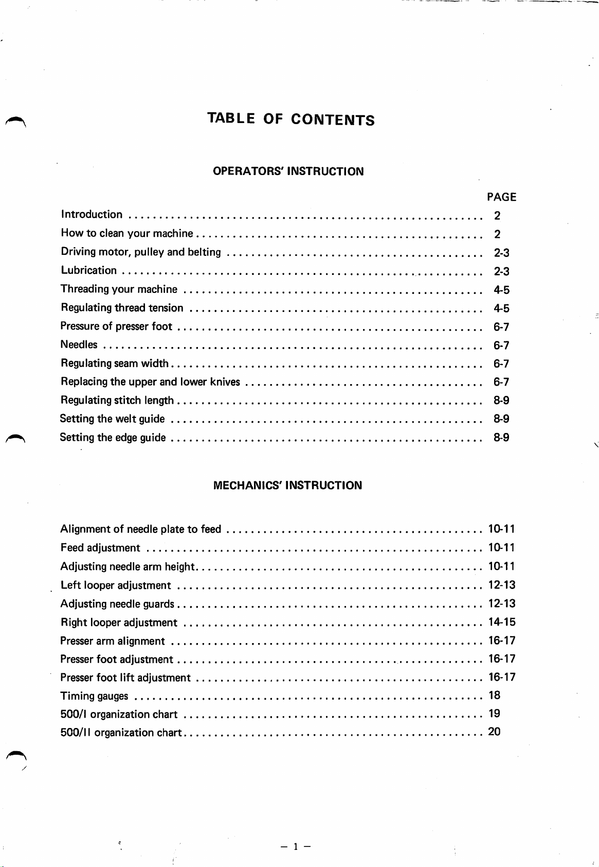
TABLE
OF
CONTENTS
Introduction
Howtoclean
Driving
Lubrication
Threading
Regulating
Pressureofpresser
Needles
Regulating
Replacing
Regulating
Setting
Setting
motor,
your
thread
seam
the
stitch
the
welt
the
edge guide
your
pulley and belting 2-3
machine
width
upper
guide 8-9
machine
tension
foot
and
length
OPERATORS'
INSTRUCTION
PAGE
2
2
2-3
4-5
4-5
6-7
6-7
6-7
lower knives 6-7
8-9
8-9
Alignmentofneedle
Feed
adjustment
MECHANICS'
platetofeed 10-11
INSTRUCTION
10-11
Adjusting needle arm height 10-11
Left
looper
adjustment
12-13
Adjusting needle guards 12-13
Right looper
Presser
Presser
Presser
arm
foot
foot
adjustment
alignment
adjustment
lift
adjustment
14-15
16-17
16-17
16-17
Timing gauges 18
500/1 organization
500/11 organization
chart
chart
19
20
- 1 -
Page 3
OPERATORS'
INSTRUCTION
INTRODUCTION
You
are
about
designed
overlock.
by
featurestoassist
easier
handling
increase
smoothly,
quietly.
machines
OPERATOR'S
HOW
your
The
TO
to
the
In
this
and
production.
has
automatic
operate
people
machine
you,asthe
faster
an
overlook
who
first
introduced
you
will
operator,toenjoy
sewing
It is
that
easytothread,
lubrication,
find
will
Willcox & Gibbs class 500/1 &
are
the
machines
FAVORITES".
CLEAN
known
YOUR
machine
all
help
feeds
and
as
"THE
the
the
the
you
runs
MACHINE
Cleaning
It is
release
out
from
needle plate. Blow
brush. Replace covers and return
position.
DRIVING
BELTING
Each
following specifications:
1. Clutch motor: 3 phase; 2 pole;
is
2. Motor speed is approximately 2,900 r.p.m. for
50 Hz or
3. Beltingshould be V belt. Type
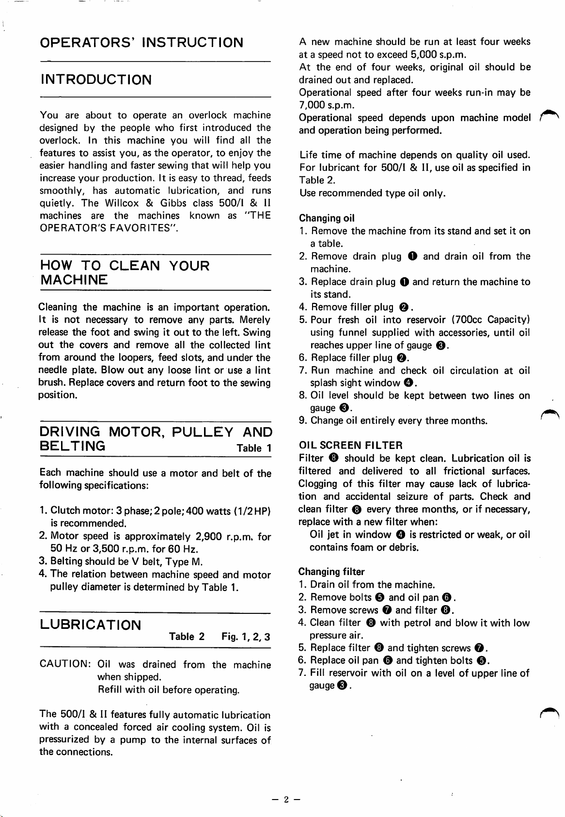
4. The relation between machine speed and
pulley diameter is determined by Table 1.
LUBRICATION
CAUTION:
the
machine is an
not
necessary
the
foot
the
covers
around
machine
recommended.
the
3,500
Oil
when
Refill with oil before operating.
important
to
remove
and
and
swing it
remove
outtothe
all
loopers, feed slots,
out
any
loose
MOTOR,
should
useamotor
r.p.m. for
was
drained
PULLEY
60
Table
shipped.
any
parts. Merely
the
collected
and
lintoruse a
foottothe
and
400
watts {112HP)
Hz.
M.
2 Fig.
from
the
operation.
left. Swing
lint
under
the
lint
sewing
AND
Table 1
beltofthe
motor
1,2,
machine
11
3
A
new
machine
ataspeed
At
the
drained
nottoexceed
end
out
Operational
7,000
s.p.m.
Operational
and
operation
Life
time
of
For
lubricant
Table
2.
Use
recommended
Changing
1.
Remove
a
oil
table.
2. Remove drain plug O and drain oil from
machine.
3. Replace
its
stand.
4. Remove filler plug
5.
Pour
fresh oil
using
funnel
reaches
upper
6. Replace filler plug
7.
Run
machine
splash sight
8. Oil level
gauge
©.
9. Change oil
OIL
SCREEN
of
and
speed
speed
being
machine
for
the
drain
window
should
entirely
FILTER
four
machine
supplied
should
be
5,000
weeks,
run
at
least
s.p.m.
original oil
four
should
weeks
replaced.
after
four
depends
weeks
upon
run-in
machine
may
model
performed.
depends
on
quality
oil
used.
500/1 & II, use oil as specified in
type
oil
only.
from
its
stand
and
setiton
plug O
and
return
the
machine
0.
into
reservoir
with
line of gauge
(700cc
accessories,
0.
Capacity)
until
0.
and
check
oil
circulation
at
O.
be
kept
every
between
three
two
months.
lines
be
be
the
to
oil
oil
on
Filter 0 should be kept clean. Lubrication oil is
filtered
Clogging
tion
clean
replace
Changing
1.
2. Remove bolts 0 and oil pan
3.
4. Clean filter 0 with petrol and blow it with low
5. Replace filter 0 and tighten screws
6. Replace oil pan 0 and tighten bolts
7. Fill reservoir
and
of
and
accidental
filter
withanew
Oil
jetinwindow
contains
filter
Drain
oil
Remove
pressure
gauge
0.
delivered
this
filter
seizure
0 every
three
filter
O is restrictedorweak,oroil
foam
or
debris.
from
the
machine.
screws0and
air.
with
oil on a levelofupper
to
all
frictional
may
cause lack
of
parts.
of
Check
months,orif necessary,
when:
©.
filter
0.
0.
0.
surfaces.
lubrica
and
line
of
The 500/1 & II features fully automatic lubrication
with a concealed forced air cooling system. Oil is
pressurized by a
the
connections.
pump
to
the
internal
surfaces
of
- 2 -
Page 4
MACHINE
(S.P.M.)
4,600
5,000
5,300
5,500
5,800
6,000
6,300
6,700
7,000
MACHINE
(S.P.M.)
4,600
5,000
5,300
5,500
5,800
6,000
6,300
6,700
7,000
SPEED
SPEED
MOTOR
MM
95
105
110
115
120
125
130
140
145
MOTOR
MM
80
85
90
95
100
105
110
115
120
PULLEY
INCHES
3-3/4
4-1/8
4-3/8
4-1/2
4-3/4
4-7/8
5-1/8
5-1/2
5-3/4
PULLEY
INCHES
3-1/8
3-3/8
3-5/8
3-3/4
4
4-1/8
4-3/8
4-1/2
4-3/4
50
60
Hz
DIAMETER
PULLEY
in
Hz
DIAMETER
PULLEY
in
U.S.A.
636
641
643
644
646
647
651
654
656
U.S.A.
631
633
635
636
640
641
643
644
646
SIZE
SIZE
Fig.
Fig.
I
2
Notel:
Note
Kinematic
Machine pulley diameter is
2:
Motor
its
outer
Viscosity
(centistokes)
Viscosity
Index
Pour
Point
(®F)
Load
Carrying
Capacity (kg/cm^)
pulley
diameter.
lOO^F
210®F
VI
(A)
VI (B)
Table
diameter
more
1
Brand
19.01
130.0
123.5
-59.0
(170
4.04
than
should
"A"
12
psi.)
60mm
{2.36").
be measured in
Brand
more
14.57
147.5
142.5
-63.5
(170
3.57
than
"B"
12
psi.)
Fig.
3
Table
2
- 3 -
Page 5
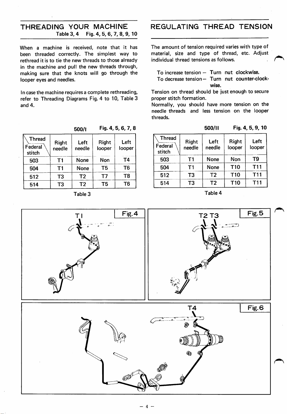
THREADING
When
been
rethread
in
making sure
looper
In case
refer
and
a
machine
threaded
it istotie
the
machine
eyes
and
the
machine
to
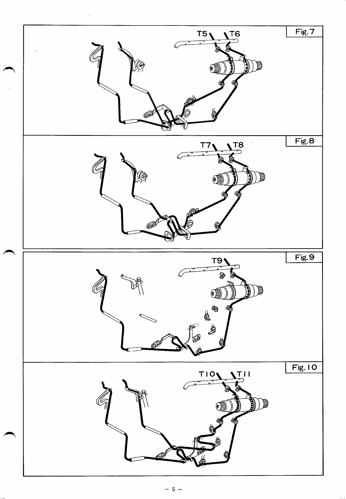
Threading Diagrams Fig. 4 to 10, Table 3
4.
YOUR
MACHINE
Table3,4 Fig.4,5,6,7,8,9,
is received,
correctly.
the
new
and
pull
the
that
the knots will go through
note
that
The
simplest
threadstothose
new
threads
needles.
requires a
complete
rethreading,
10
it
has
way
to
already
through,
the
REGULATING
The
amount
material, size and
individual
To
increase
To
decrease
Tension
proper
of tension required varies with
thread
tension
tension—
on
thread
stitch
formation.
type
tensions
—
should
THREAD
of
thread,
as
follows.
Turn
Turn
wise.
be
just
TENSION
type
etc. Adjust
nut
clockwise.
nut
counter-clock
enoughtosecure
Normally, you should have more tension on
needle
threads.
threads
and
less
tension
on
the
of
the
looper
Thread
Federal
stitch
503
504
512
514
Right
looper
4
Fig.4,5,9,10
Left
looper
Non
T10
T10
T10
T9
Til
Til
Til
500/1
Right
\
needle
Left
needle
Fig.4,6,6,7,
Right
looper
\
T1
T1
T3
T3
None
None
T2
T2
Table
Tl
Non
T5
T7
T5
3
Left
looper
T4
T6
T8
T6
Fig.
8
\
Thread
Federal \
stitch
503
504
512
514
Right
needle
\
T1
T1
T3
T3
4
T2
500/11
Left
needle
None
None
T2
T2
Table
T3
- 4 -
Fig.
6
Page 6
T7\
\T8
Fig.
Fig.
7
8
TlOv
\TII
Fig.
Fig.
9
IO
- 5 -
Page 7
PRESSURE
OF
PRESSER
FOOT
Fig.
11
Pressure
thumb
just
stitch
material
little
stitches.
of
screw
enough
formation.
and
pressure
presser
Oto
give it
foot
Pressureonpresser
feed
material
Too
more
may
cause
is regulated by
foot
and
obtain
much
stretch
pressure
thanitneeds.
uneven
means
should
proper
may
feedings
spoil
Too
NEEDLES
Fig.
11,12
Generally
by
the
sewn.
Changing
1.Turn
at
2. Lift up
left.
3. Loosen
with
4. Insert new needle in
until needle rests against pin
5. Tighten
6.
Return
7.
Make
needle
the
size of needle should be determined
size of thread or weight of material
needles
hahdwheel
its
highest
the
lever
nut
machine
until
position.
0 and
0 using
and
needle
swing
socket
remove
the
drive
presserarm O to the
wrench furnished
old
needle.
groove 0
0.
nut
0 securely.
arm O
sure
holeinneedle
to
needle
the
sewing
descends
plate.
position.
in
the
arm
center
of
to
0 is
clamp
of
the
8. On two needle machine, be sure to keep shim ©
at
the
right position
REGULATING
1. Lift up lever 0 and swing arm O
2.
Turn
lowest
3. Loosen
as
4.
Loosen
rightorleft
then
5. Loosen
positionbyspring
6.
Tighten
handwheel
position.
screw
far
as it will go
screw
tighten
screw
screw
©.
0
until
screw
0,
0.
7. Return arm Otothe
or
between
SEAM
until
upper
Pull
thumb
and
lightly
and
move
the
desired
0.
then
holder
action.
sewing position.
two
needles.
WIDTH
Fig.
11,13
to
the
left.
knife
nut
tighten
holder
widthisobtained,
0 will
is
at
©
to
the
left
screw
©
to
0.
the
return
be
of
or
be
its
to
Needle
Best
size
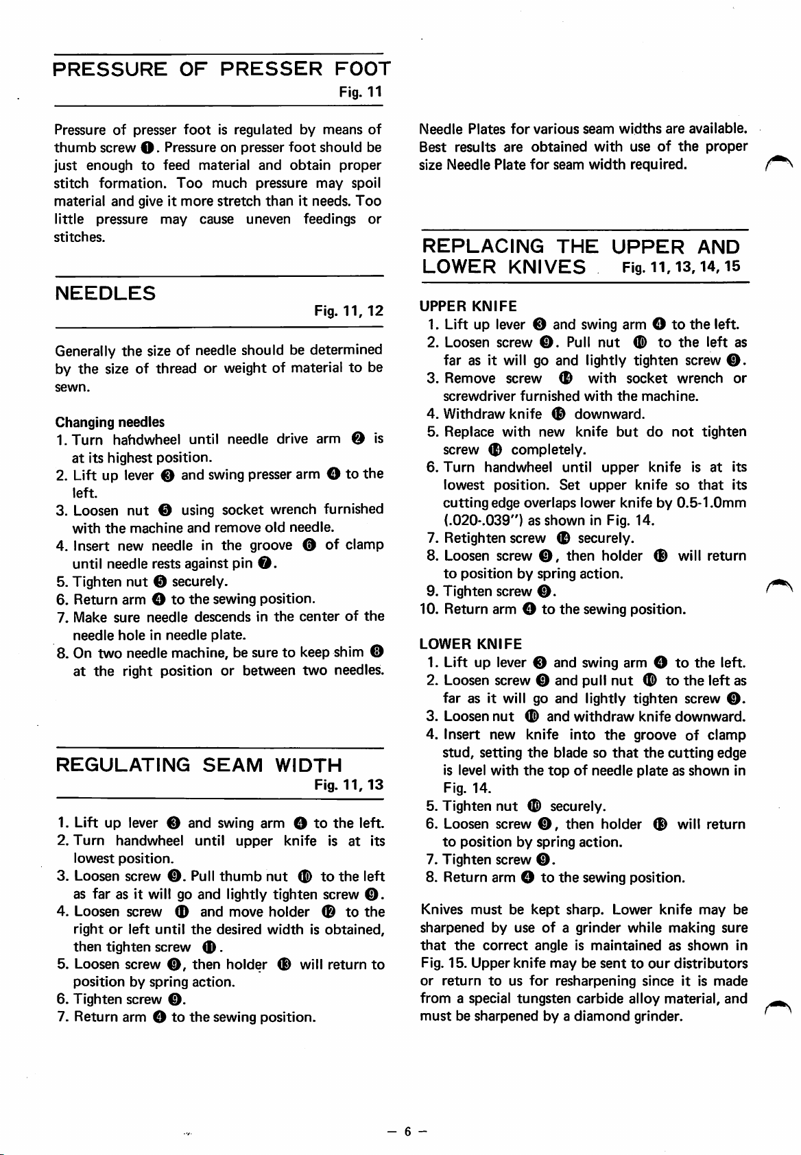
REPLACING
LOWER
UPPER
Plates
results
Needle
KNIFE
for
various
are
obtained
Plate
for
KNIVES
seam
THE
seam
with
width
widths
use
required.
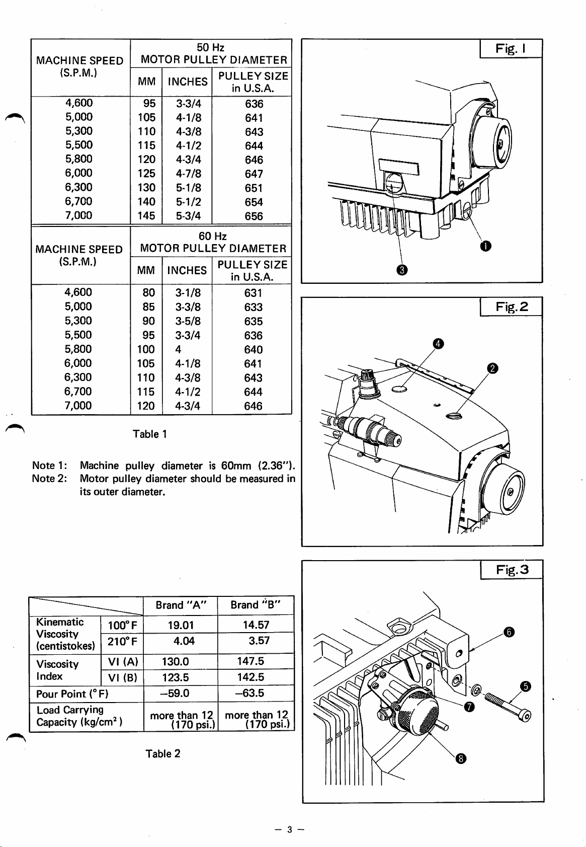
UPPER
Fig.
ii,
are
of
the
13,14,15
1. Lift up lever 0 and swing arm Otothe
2.
Loosen
screw
0.
Pull
nut
©
to
the
far as it will go and lightly tighten screw
3.
Remove
screwdriver
4.
Withdraw
5.
Replace
screw
6.
Turn
lowest
cutting
(.020-.039")asshown
screw
furnished
knife
with
0
completely.
handwheel
position.
edge
overlaps
0
©
new
Set
with
with
downward.
knife
until
upper
upper
lower
in Fig. 14.
socket
the
but
knifeby0.5-1.0mm
machine.
do
knife
knife
wrench
not
so
7. Retighten screw 0 securely.
8. Loosen
to
9.
Tighten
10. Return arm Otothe
LOWER
1. Lift up lever 0 and swing arm O
2. Loosen screw 0 and pull
far
3.
Loosen
4.
Insert
stud,
is level
Fig.
5. Tighten
6. Loosen
to
7.
Tighten
8. Return arm O
Knives
sharpened
that
Fig. 15.
or
return
from
mustbesharpened
screw
0,
positionbyspring
screw
KNIFE
0.
as it will go
nut
©
and
new
knife
setting
14.
positionbyspring
with
nut
screw
screw
the
the
topofneedle
© securely.
©,
0.
to
must
be
kept
by
useofa
the
correct
Upper
to
a special
angleismaintained
knife
maybesenttoour
us
for
tungsten
byadiamond
then
holder
action.
sewing position.
nut
and
lightly
withdraw
into
the
blade so
then
the
sharp.
resharpening
that
holder
action.
sewing position.
Lower
grinder
carbide
© will
to
©
to
tighten
knife
downward.
groove
the
cutting
plateasshown
© will
knife
while
making
as
distributors
since
it is
alloy
material,
grinder.
available.
proper
AND
left.
left
tighten
is
at
that
return
the
the
left as
screw
of
clamp
edge
return
may
shown
made
as
0.
or
its
its
left.
0.
in
be
sure
in
and
- 6 -
Page 8

Fig.
I I
Upper knife
Fig.
14
.020-039"
1
Needle plate
top
mnni/
Lower
Fig.
surface
t<nife
I2
Fig.
I3
- 7 -
Fig.
I5
Page 9
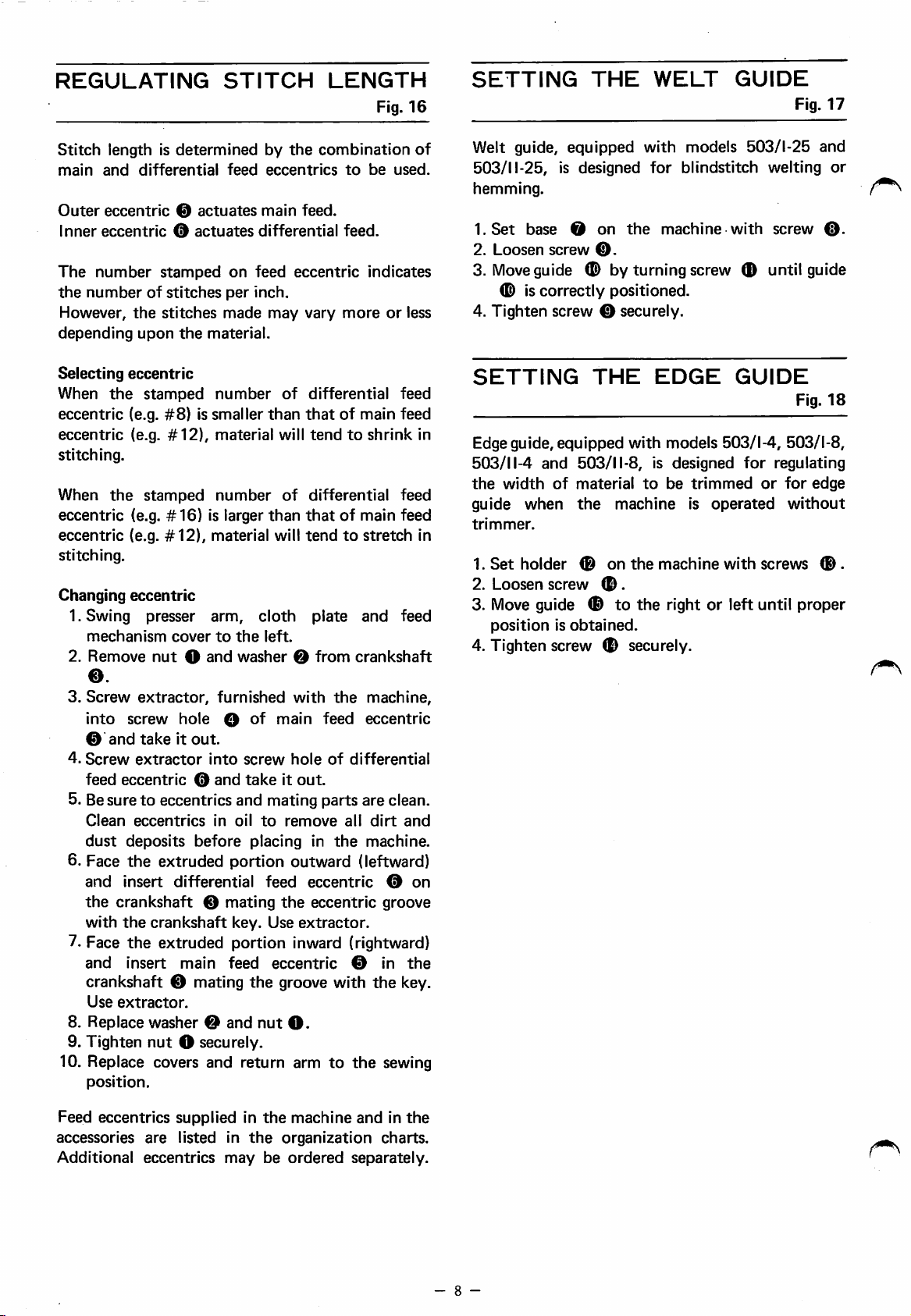
REGULATING
STITCH
LENGTH
Fig.
16
SETTING
THE
WELT
GUIDE
Fig.
17
Stitch
main
Outer
Inner
The
the
However,
depending
Selecting
When
eccentric
eccentric
stitching.
When
eccentric
eccentric
stitching.
Changing
lengthisdetermined
and
differential
eccentric
eccentric
number
0
0
stamped
numberofstitches
the
stitches
upon
eccentric
the
stamped
(e.g.
#8)
(e.g.
#12),
the
stamped
(e.g.
#16)
(e.g.
#12),
eccentric
1. Swing presser
mechanism
2.
Remove
0.
3.
Screw
into
0
4.
Screw
feed
and
eccentric
cover
nut
extractor,
screw
takeitout.
extractor
actuates
actuates
the
material.
number
is smaller
material
number
is larger
material will
arm,
to
O
and
furnished
hole
into
0
and
by
feed
eccentrics
main
differential
on
feed
per
inch.
made
cloth
the
left.
washer
O
of
screw
takeitout.
the
combination
feed.
feed.
eccentric
may
vary
moreorless
of
differential
than
thatofmain feed
will
tendtoshrink
of
differential
than
thatofmain feed
tendtostretch
plate
0
from
with
the
oiai"
feed
hole
of
to
be
indicates
and
crankshaft
machine,
eccentric
differential
5. Besuretoeccentrics and mating parts are clean.
Clean
dust
6. Face
and
the
with
7. Face
and
crankshaft 0 mating
8. Replace
9.
Tighten
10. Replace covers and return arm
deposits
the
insert
crankshaft
the
the
insert
Use
extractor.
position.
eccentrics
extruded
crankshaft
in
before
portion
differential
0
mating
key. Use
oil
placing
to
feed
remove
in
outward
eccentric
the
eccentric
extractor.
all
the
(leftward)
extruded portion inward (rightward)
main
washer0and
nut
O securely.
feed
eccentric
the
groove with
nut
O.
to
0 in
the
dirt
machine.
0
groove
the
sewing
used.
feed
feed
feed
and
the
key.
of
on
Welt guide, equipped with models 503/1-25 and
503/11-25, is
hemming.
I.Set
2.
3.
base
Loosen
Move
O
screw
designed
on
0.
the
for
machine
blindstitch
with
welting
screw
or
0.
guide 0 by turning screw (D until guide
/^^
0 is correctly positioned.
4. Tighten screw 0 securely.
trimmed
is
operated
with
GUIDE
for
regulating
or
screws
Fig.
for
edge
without
0 .
18
SETTING
in
in
Edgeguide, equipped with models 503/1-4, 503/1-8,
503/11-4
the
guide
trimmer.
1.
Set
2.
Loosen
3.
Move
positionisobtained.
and
width
when
holder
guide 0 to the right or left until proper
THE
EDGE
503/11-8, is designed
of
material
the
0
screw
machine
on
the
0.
to
machine
be
4. Tighten screw 0 securely.
Feed
eccentrics
accessories
Additional
supplied in
are
listed in
eccentrics
may
the
the
organization
be
ordered
machine
andinthe
charts.
separately.
- 8 -
Page 10

Fig.
Fig.
I 6
I7
- 9 -
Fig.
I8
Page 11

MECHANICS'
ALIGNMENT
PLATE
TO
INSTRUCTION
OF
NEEDLE
FEED
Rg.
19.20.21
Generally feeds should be in position as shown in
Fig. 19. Each row of main and differential feeds
rests
in
the
center
For
503/1-25
even and slightly touching needle plate
side
O.
If this setting is incorrect, reset as follows.
as
follows.
1. Release pressure on
the
left.
2. Loosen screw O and move
right.
3.
Loosen
right.
screw
4. Loosen screws O
5. Check
the
plate key and move plate
point
O-
6. Tighten screws 0 and
7. Replace
8.
Make
needle
FEED
Standard
3/64")
back
as
shown
A
straight
main
Standard
above
Replacing
1.
Turn
position.
2. Release
the
3.
Swing
4.
Loosen
5.
Remove
6.
Replace
or
then
7. Replace
8.
Return
position.
both
sure
holeinneedle
ADJUSTMENT
heightofmain feed is 0.8-1.2mm (1/32-
above
tooth
when feeds areattheir
in Fig.
edge
and
differential
heightofauxiliary
needle
left.
plate.
feeds
handwheel
pressure
out
cloth
screw0and
screws 0
with
lowering
tighten screws
tube
cloth
of
each
slot
of
and
0
503/11-25,
foot
and
move
and
0.
set
differential feed
and swing
upper
lower
needle
knifetothe
knife
out
at
foot
plate.
right
to
the
groove of needle plate is on needle
to
touch evenly at
O.
knives
needle
the
22.
canbeplaced
new
feeds
0 and tighten screw
into
descends
plate.
surface
feeds.
until
feeds
on
foot
platetothe
remove
and
feeds
feeds
until
proper
0.
plate
and
position.
in
the
center
Fig.
of
needle
highest position
across
the
feedis0.5mm
areattheir
and
swing
left.
tube
0.
0.
and
set
feeds
heightisobtained,
0.
foot
to
of
22,
23,
plate
at its
topofthe
(.020")
highest
out
foot
by
raising
the
sewing
the
24
to
to
Feed dogs have generally been preset at the factory
withafront
to
back
tilt
when
feeds
areattheir
highest position as shown in Fig. 22.
Tilting
1.
2. Release pressure on
3. Swing
feeds
Turn
handwheel
position.
the
left.
out
cloth
until
feeds
foot
platetothe
areattheir
and swing
left.
out
highest
foot
to
4. Loosen screw 0 and turn screw 0 with a
screwdriver
until
proper
tiltisobtained.
5. Tighten screw 0 .
6. Return
position.
Woven
Knit material —
ADJUSTING
HEIGHT
Turn
position. Use timing gauge, check
between
plateasspecifiedinTable
1. Release pressure on
the
2. Push up cover
cloth
material
handwheel
the
pointofneedle
left.
plate
—
Set
Tilt
than
NEEDLE
Tables
until
0.
and
feeds
feeds
the
needle
5.
foot
foot
level.
higher in
rear.
Fig.
and
and
to
the
ARM
21,25,26,27
is
at
its
the
the
topofneedle
swing
out
sewing
the
front
highest
clearance
foot
to
3. Slightly loosen screw 0 .
4. Move arm
descends
needle
5.
Reset
belowatits
plate.
arm
in
the
0
highest
to
right
center
to
correct
position.
or
left until needle
of
the
needle
clearance
hole
in
as listed
6. Tighten screw 0 securely.
7. Return cover 0 and
position.
At this time, with arm 0 down, checktosee
there
needle
Fig.
27.
is clearance
holeinneedle
between
plate
foot
to
the
front
and
needleasshown
the
sewing
that
edgeofthe
in
If clearance is insufficient, loosen screws O and
move
clearance
needle
MODEL
500/1
500/11
is
obtained.
plate
back
CLEARANCE
MM
9.8
10.3
and
forth
until
INCH
.386
.406
correct
Table
-10-
5
Page 12

Fig.
I9
Fig.
20
Fig.
2 I
Fig.
Fig.
24
25
0.8
-1.2inni
1/32-3/64"
Fig.
Fig.
22
23
0.8-1
32-.039"
Fig.
Fig.
.Omm
26
27
-
11
-
Page 13

LEFT
LOOPER
ADJUSTMENT
Table
6 Fig.
28,
29,
30,
31
ADJUSTING
NEEDLE
GUARDS
Fig.
32
1. Release
the
left.
2.
Swing
cover.
3.
Remove
4.
Remove
page.
5.
Remove
6.
Turn
extreme
pressure
out
cloth
needle
needle
feedsasinstructed
handwheel until
left
on
platetothe
plate.
guards
position.
foot
looper
and
swing
left
as
instructed
on
page
lever O is in
and
out
open
12.
foot
on
to
front
this
the
7. Loosen screw o and remove looper..
8.
Insert
down
0 and tighten screw
9. Loosen
of
clearance
screw
On
from
clearanceasshown
10.
Turn
centerline
11. Move lever O back and forth along its
so
then
12.
The
needleasshown
13. Recheck clearance
securely.
14. Replace feeds as
new
until
screwOwith
looper
from
as listed
O-
the
two
centerline
handwheel
of
that
the
tighten
point
looper
baseoflooper
into
O.
centerline
below
needle
screw
of
machine,
of
in Fig.
until
needle.
looper
point
O.
looper
should
in Fig.
and
instructedonpage
lever O
shank
wrench
of
and
left
reaches
and
needletocorrect
lightly
set
pointoflooper
needle
29.
looper
just
point
touches
beinthe
30.
tighten screw O
and
adjust
to
is in
shaft
12.
push
shaft
point
tighten
correct
needle,
scarf
the
©
of
15. Replace needle guards as instructedon this page.
16.
17.
Replace
Return
sewing
needle
cloth
plate,
position.
plate.
front
cover
and
foottothe
Machines
guards.
1. Release
the
2.
Swing
3.
Remove
4.
Remove
5. Loosen screw 0 and remove guard
REAR
are
fitted
Set
rear guard 0 first.
pressure
left.
out
cloth
needle
feedsasinstructed
NEEDLE
GUARD
with
front
on
foot
platetothe
plate.
and
left.
on
and
swing
page
rear
out
12.
O.
needle
foot
6. Loosen screw 0 and remove rear guard
7. Replace with new guard 0 and lightly
tighten screw
8.
Turn
handwheel
is
oppositetothe
9. Adjust guard 0 back
touches
10.
Tighten
FRONT
NEEDLE
11. Replace
12.
Adjust
0.2mm
O.
13.
Tighten
14. Recheck setting
0.
15. Replace
16. Replace
17.
Return
position.
CAUTION:
0.
until
the
pointofleft
centerlineofneedle.
and
forth
needle
without
deflecting
screw 0 securely.
GUARD
with
new
guard
0.
guard 0 until
(.004
.008")
there
between
is a
needle
screw 0 securely.
after
tightening screws 0 and
feedsasinstructedonpage
needle
cloth
Needle
needle
plate.
plate
guards
size is
and
foot
must
changed.
to
be
looper
until it
needle
point.
spaceof0.1-
and
guard
12.
the
sewing
reset
when
to
0.
just
Note:
FEDERAL
when
the
STITCH
503
504
512
514
Left
machine.
Looper
looper
viewed
is self
MODEL
503/1,
504/1, II
514/1,
514/1,
has a
from
2.3mm
above
settingasshown
GAUGE
II
2.0
II
3.0
II
2.0
Table
6
(3/32")
looper
lever in
in Fig.
CLEARANCE
MM
INCH
5.3
.209
5.3
.209
5.3
.209
4.3
.169
5.3
.209
offset
31.
-12-
Page 14

Fig.
28
Fig.
30
Fig.
29
2.3niin
3/32"
t . .
0.1
- 0.2min
.004-.008"
Fig.
Fig.
31
32
-13-
Page 15

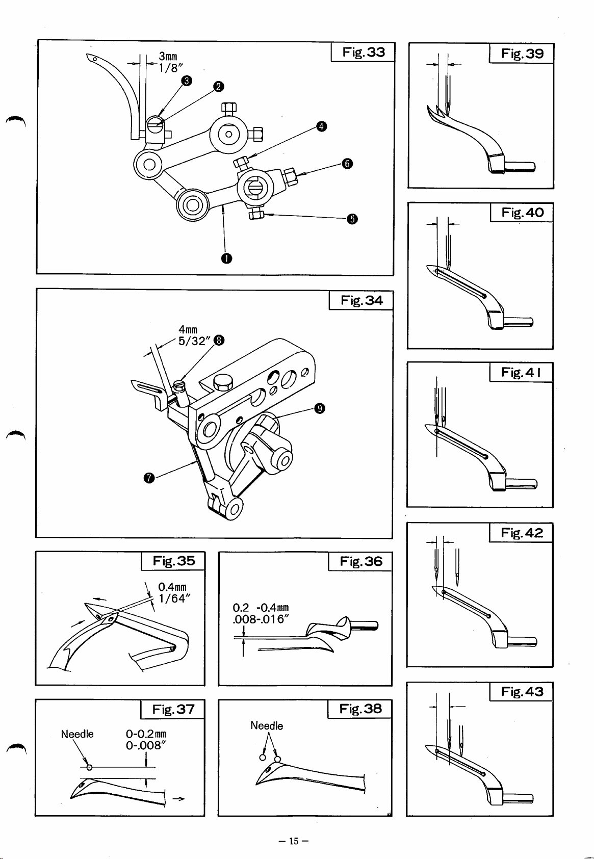
RIGHT
LOOPER
ADJUSTMENT
Table1.8 Fig.33-
500/1
1. Release pressureonfoot
the
left.
2. Swing
Open
3.
plate.
4.
5.
6.
Turn
lowest
7. Loosen
the
lever O
8.
Tighten
9.
Turn
left
10. Loosen screws O
Remove
Remove
back
handwheel
position.
out
cloth
platetothe
front
cover
needle
plate.
feedsasinstructed
handwheel
position.
screw
edge
to
3mm
until
and
of
loopertothe
(1/8").
screw 0 lightly.
until
and
11. Slightly loosen screw 0
or
spreader
terline
below
upward.
12. Make sure it is
(bottom
of
needle
by moving
to
connection
correct,
and
remove
connection
adjust
looperisat
0.
of
correct
then
and
and
V groove)
lightly.
13.
Turn
handwheel
both
loopers
possible
35
14.Ifright
and
without
36.
looper
nectionOdownward.
left
until
correct
below.
loopers
Turn
pass as
15. If clearance is
upward.
correct
Turn
Move
clearance
handwheel
passasshown
16. Tighten screw
slowly
pass
they
and
should
touching
strikes
left
Move right
clearance
handwheel
shown
too
right
and
in Fig.
0,
and
in Fig.
much,
looper
is
obtained
observe
35.
and tighten screws O and
0 alternately.
17.
Rotate
looper
Fig.
looper in its lever © and adjust right
so
that
both
loopers
36.
18. Retighten screw 0 securely.
19.
Looper
as
On
that
touches
rightasshown
20.
Replace feeds as
21.
Replace
22.
Replace
cover.
23.
Return
position.
FEDER
AL
STITCH
503
504
512
514
shown
the
upper
should
in Fig.
two
the
needle
looper
cloth
MODEL
503/1,
504/1,
514/1,
514/1,
not
strike
37.
needle
portion
right
machine,
of
needleinits
in Fig.
38.
instructedonpage
plate.
thread
plate
and
GAUGE
II
II
2.0
II
3.0
II
Table
the
plate
7
swing
out
left.
looper
on
page
12.
O isatits
the
clearance
faceoflooper
its
adjust
looper
from
clearance
O
downward
tighten
observe
screw 0
that
be as close as
as
shown
looper,
move
loopertothe
is
obtained
observe
that
35.
move
connection
to
the
right
as
listed
that
both
pass as
needle
adjust
shown
when
looper
backoflooper
movementtothe
12.
and
close
foot
to
the
CLEAR
ANCE
MM
-1.0
3.0
3.0
0 0
3.0
INCH
.118
.118
-.039
.118
43
foot
to
thread
from
extreme
eye
cen-
as
listed
or
when
in Fig.
con
as
listed
both
O
until
below.
loopers
passing
so
just
front
sewing
FIG.
39
40
41
42
43
in
500/11
1. Release pressure on
the
left,
2. Swing
3. Open
4.
5.
6.
7. Loosen screw 0
out
cloth
platetothe
front
cover and remove looper
plate.
Remove
Remove
Turn
lowest
needle
plate.
feedsasinstructed
handwheel until
position.
and
the
back edgeofloopertothe
0
to
4mm
(5/32").
8. Tighten screw © lightly.
9.
Turn
left
handwheel
position.
until
10. Slightly loosen screw
11. Adjust looper eye or spreader
groove)
from
centerline
clearance as listed below by moving lever 0
downwardorupward.
12. Make sure it is correct, then tighten screw 0
lightly.
13.
Turn
handwheel
both
possible
and
36.
loopers
without
slowly
pass
touching as shown in Fig.
14. If right looper strikes left looper, move lever
0
downward.
until
correct
below.
loopers
Turn
pass as
15. If clearance is
Move
clearance
right
handwheel
as
shown
in Fig.
clearance
handwheel
too
looper
is
obtained
and
Move
shown
much,
observe
35.
16. Tighten screw 0 securely.
17.
Rotate
looper
Fig.
36.
looper
so
that
in its
both
18. Retighten screw 0 securely.
19.
Looper
as
On
that
touches
rightasshown
20.
Replace
21.
Replace
22.
Replace
cover.
23.
Return
position.
Note:
shown
the
upper
should
in Fig.
two
the
not
37.
needle
portion
right
needle in
in Fig.
feedsasinstructedonpage
needle
cloth
looper
plate.
thread
plate
Various right loopers are provided as listed
on page 18 for use with various size needles.
For
easeofidentification
been
marked
-14-
withalooper
foot
and
looper
adjust
looperisat
©.
and
they
should
right
is
and
in Fig.
move
to
the
as
that
holder
loopers
strike
machine,
of
the
38.
plate
and
swing
out
left.
on
page
12.
lever 0 isatits
the
clearance
left sideoflever
its
(bottom
of
needle
observe
be as close as
looper
obtained
observe
to
35.
lever 0
right
until
listed
both
and
below.
loopers
adjust
pass as
needle
when
adjust
back
of
looper
its
movementtothe
12.
and
close
foot
to
the
some
loopers
marking.
foot
thread
extreme
to
correct
that
the
as
that
upward.
correct
shown
passing
looper
sewing
to
from
of V
when
35
left
listed
both
Turn
pass
right
in
so
just
front
have
Page 16
4inin
Fig.
Fig.
33
34
Fig.
Fig.
39
40
Fig.
35
\
0.4mm
A 1/64"
0
0.2
-0.4inm
.008-.016''
Fig.
36
Fig.4
Fig.
42
Fig.
38
Needle
0-0.2
0-.008"
Fig.
mm
37
Needle
_L
-
15
-
Fig.
43
Page 17
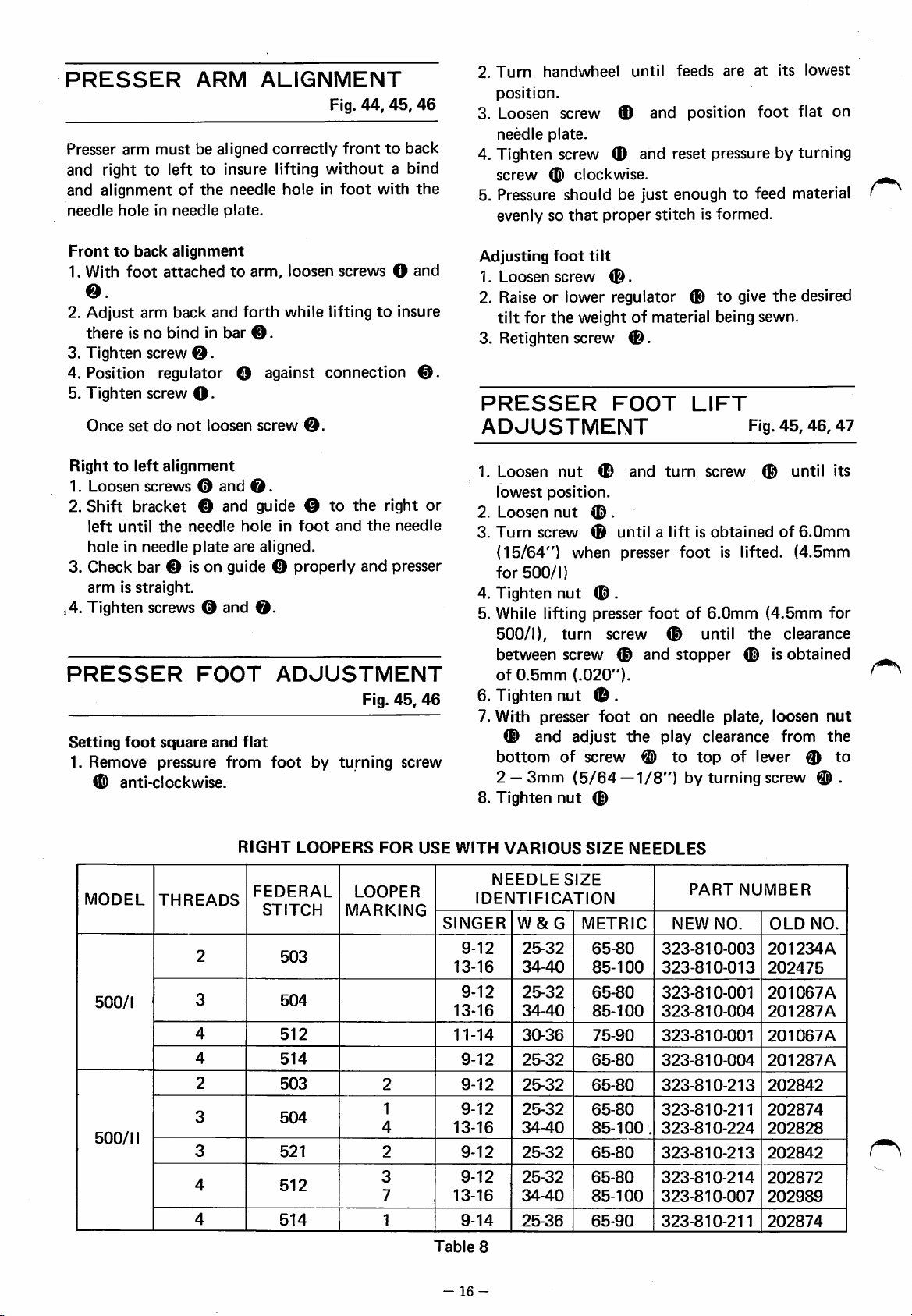
PRESSER
Presser arm
must
ARM
be aligned
ALIGNMENT
correctly
and righttoleft to insure lifting
and
alignmentofthe
needle
holeinneedle
needle
plate.
holeinfoot
Fig.
44, 45,
fronttoback
without
a bind
with
46
the
2.
Turn
handwheel
until
feeds
are
at
its
lowest
position.
3. Loosen screw
needle
plate.
and
position
foot
flat on
4. Tighten screw 0 and reset pressure by turning
screw
0
clockwise.
5. Pressure should be just enoughtofeed material
evenly so
that
proper
stitch
is formed.
Fronttoback
1. With
alignment
foot
attachedtoarm,
loosen screws O
o.
2.
Adjust
thereisno
3.
Tighten
arm
back
bindinbar
screw
©.
and
forth
while liftingtoinsure
©.
4. Position regulator O against connection
5.
Tighten
Once
Righttoleft
1.
Loosen
2.
Shift
left
holeinneedle
3.
Check
armisstraight.
,4. Tighten screws © and
PRESSER
Setting
1.
Remove
©
screw
O -
setdonot
loosen
alignment
screws©and
bracket
until
the
© and
needle
plate
bar
© is on guide ©
FOOT
foot
square
pressure
anti-clockwise.
and
hole
are
flat
from
screw
©.
guide
©.
©
in
foot
aligned.
properly
©.
ADJUSTMENT
foot
by
to
the
and
turning
right
the
and
Fig.
and
©.
or
needle
presser
45,
46
screw
Adjusting
1.
Loosen
foot
screw
tilt
0
2. Raise or lower regulator ®
tilt
for
the
weightofmaterial being sewn.
3. Retighten screw
PRESSER
0.
FOOT
ADJUSTMENT
1.
Loosen
lowest
2.
Loosen
3.
Turn
(15/64")
for
4. Tighten
5. While lifting presser
500/1),
between
of
position.
screw
500/1)
0.5mm
nut
nut
when
nut
turn
screw
(.020").
0
and
turn
0.
0
untilaliftisobtainedof6.0mm
presser
foot
0 .
footof6.0mm
screw
0
0 until
and
stopper
6. Tighten nut 0 .
7. With presser
0 and adjust
bottom
2 —
3mm
8.
Tighten
foot
the
of
screw
(5/64—1/8")
nut
0
on
needle
play clearance from
0
to
by
to
LIFT
screw
top
turning
give
Fig.
0
is lifted.
(4.5mm
the
0 is
plate,
of
lever ©
screw
the
desired
45,
46,
until
(4.5mm
clearance
obtained
loosen
47
its
for
nut
the
to
0.
MODEL
500/1
500/11
RIGHT
THREADS
2
3
4
4
2
3
3
4
4
LOOPERS
FEDERAL
STITCH
503
504
512
514
503
504
521
512
514
FOR
LOOPER
MARKING
2
1
4
2
3
7
1
USE
Table
WITH
SINGER
13-16
13-16
11-14
13-16
13-16
-16-
VARIOUS
NEEDLE
IDENTIFICATION
9-12
9-12
9-12
9-12
9-12
9-12
9-12
9-14
8
W&G
25-32
34-40
25-32
34-40
30-36
25-32
25-32
25-32
34-40
25-32
25-32
34-40
25-36
SIZE
METRIC
SIZE
65-80
85-100
65-80
85-100
75-90
65-80
65-80
65-80
85-100
65-80
65-80
85-100
65-90
NEEDLES
.
PART
NEW
NO.
323-810-003
323-810-013
323-810-001
323-810-004
323-810-001
323-810-004
323-810-213
323-810-211
323-810-224
323-810-213
323-810-214
323-810-007
323-810-211
NUMBER
OLD
201234A
202475
201067A
201287A
201067A
201287A
202842
202874
202828
202842
202872
202989
202874
NO.
Page 18

© & P
Fig.
44
© O
Fig.
46
Fig.
45
Fig.
47
®.x
\o®
/V
{:
-17-
Page 19

500/1
&
500/11
TIMING
GAUGES
500/1
RESPECTIVE
MEASURING
POSITIONS
REQUIRED
323-882-800
151
AT
500/11
cz:^
BASIC
POSITIONS
©
ON
MEASURING
323-882-202
183
A) Needle, at upper dead
point
B) Right looper,atleft dead
(Needle
sizp 9)
C) Left looper,atleft dead
(Needle
size
9)
D) Main feed dog,atupper
point
point
dead
point
from
needle
plate
toptoneedle
from left side of needle
from
left
sideofneedletolooper
from
needle
plate
top
to
to
center
top
edgeoffeed
point.
point.
of
looper eye.
teeth.
-18-
Page 20
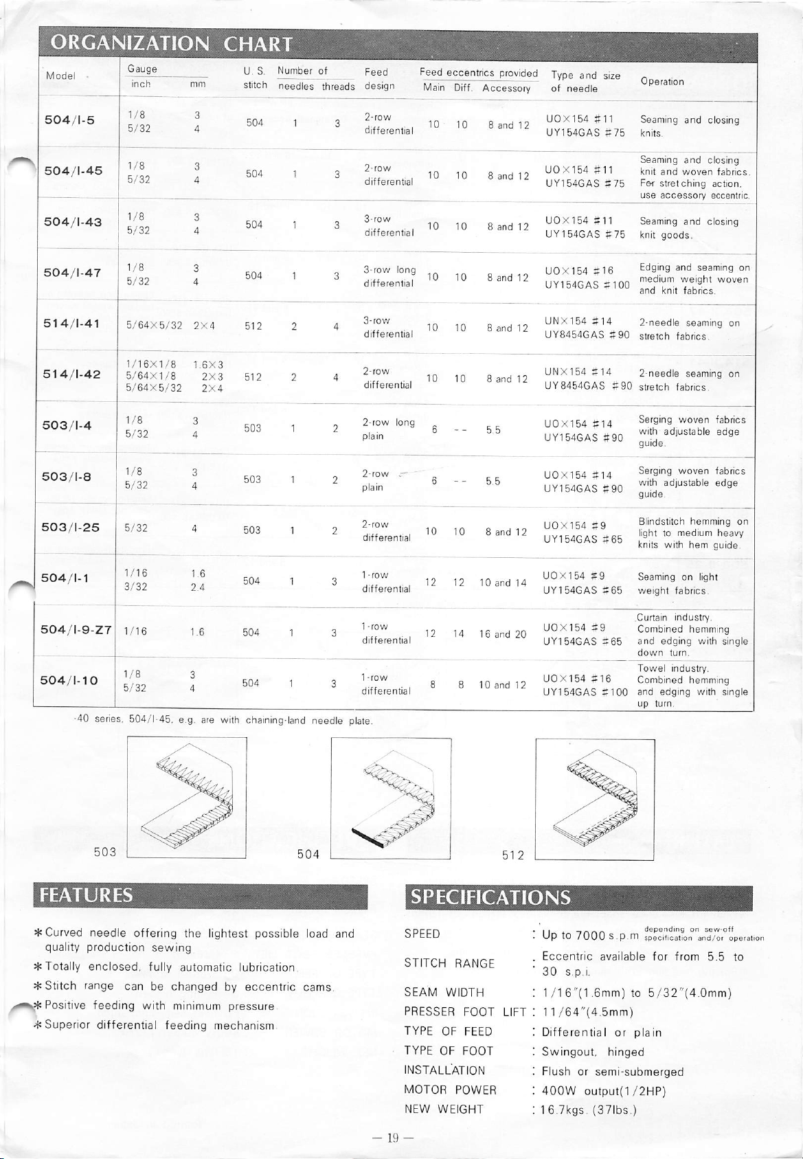
ORGANIZATION
CHART
504/1-5
i
504/1-45
504/1-43
504/1-47
514/1-41
5 1
4/1-42
503/1-4
5/64X5/32
1/16X1/8
5/64X1/8
5/64X5/32
2X4
1.6X3
2X3 512
2X4
U.S.Number
stitch
needles
504
504
504
504
512
503
1
1
1
1
1
of
threads
4
Feed
design
differential
2-row
differential
3-row
differential
3-row
differential
3-row
differential UY8454GAS
2-row
differential UY8454GAS
2-row
long
long
Feed
Main
in in
10
eccentrics
Diff.
Accessorv
10 8
B
Sanriio
provided
b ^ n UOX154 #11
and
Type
of
UY154GAS#75
12
UOX154
UY154GAS
and
needle
UGX154
UY154GAS#75
UOX154
uy154GAS#100
anH19ONX154
'-'NX154
UOX154
UY154GAS#90
#11
#11
#16
#14
#14
#14
size
#75
#90
#90
Operation
Seaming
knits.
Seaming
knit
Fsf
use
Seaming
knit
Edging
^^edium
and
2-needle
stretch fabrics.
2-needle
stretch fabrics
Serging
^^^h
and closing
and
and
woven
stretching
accessory
and
goods.
and
weight
knit
fabrics.
seaming
seaming
woven
ad|ustable
closing
fabrics.
action.
eccentric.
closing
seaming
woven
fabrics
edge
on
on
on
503/1-8
503/1-25
504/1-1
504/1-9-271
504/1-10
5/32
1/16
-40 series. 504/1-45, e.g. are
2-row
503
503
504
1
1
1
504 1 3 12 14 16
504
with
chaining-land
1 3
needle
plate.
-•
pla in
differential
differential
differential UY154GAS
1-fow
differential UY154GAS
10
12
g g
10
12 10
10
8
and
and
and
and
12
14
20
12
U0X154 #14
UY154GAS
UOX154
UY154GAS
'-'0X154
UY154GAS
'-'0X1S4
#9
#9
#16
Serging
#90
Blindstitch
#66
knits with hem guide.
Seamingonlight
#65
weight
.Curtain industry.
Combined
#65
and
edging with single
down turn.
Towel
Combined
#100
and edging with single
up
turn.
woven
hemming
fabrics.
hemming
industry.
hemming
fabrics
on
I
* Curved
quality production
*Totally
needle
enclosed,
offering the lightest possible load and
sewing
fully automatic lubrication.
* Stitch range can be changed by eccentric cams.
Positive
•4;
Superior differential feeding mechanism
feeding
with minimum
pressure
SPEED
STITCH
SEAM
PRESSER
TYPE
TYPE
INSTALLATION
MOTOR
NEW
RANGE
WIDTH
FOOT
OF
FEED
OF
FOOT
POWER
WEIGHT
LIFT
l^^f-ir\r\r\
Upto/UUUS.p.m
Eccentric
30
s.p.i.
1/16"(1.6mm)to5/32"(4.0mm)
II
/64"(4.5mm)
Differential
Swingout,
Flush or
400W
16.7kgs.
depending on sew-off
specification and/or operation
available
for
or
plain
hinged
semi-submerged
output{1/2HP)
(37lbs.)
from
5.5
to
Page 21
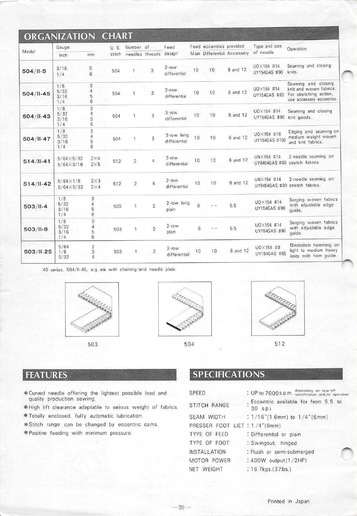
ORGANIZATION
CHART
U.S.
stitch
Number
needles
of Feed Feed eccentrics
threads
design
Main Differential
provided
Accessory
Type and size
of
needle
Operation
504/11-43
504/11-47
514/11-41
514/11-42
503/11-4
503/11-8
504
1/4
5/64X5/32
5/64X3/16
5/64X1/8
5/64X5/32
1/8
5/32
3/16
1/4
1/8
5/32
3/16
1/4
5/64
1/8
5/32
40 series. 504/11-45, e.g. are with chaining-Iand
2X4
2X5
2X3
2X4
3
4
5
6
3
4
5
6
2
3
4
503
1
1
needle
2-row
differential
2-row
differential
3-row
differential
3-row
differential
3-row
differential
2-row
differential
2-row
plain
2-row
differential
plate.
long
long
10
10 10
10 10
8
10
and
UOX154 fi14 Seaming and closing
12
UY154GAS
#90
knits.
Seaming and closing
UOX154
#14
knit
and
woven
seaming
fabrics.
seaming
fabrics.
seaming
fabrics.
-Tm"
hemming
medium
fabrics.
on
on
*!?""
heavy
guide.
on|
on
8
and
12
UY154GAS
8
and
8
and
8
and
8
and
UOX154 #14 Seaming and closing
12
UY154GAS
UOX154
12
IIV164rAS
UY154GAS#100
UNX154
12
UY8454GAS
UNX154
1 2
UY8454GAS
UOX154
u?r5iGAS
UOX154
UY154GAS
8
and
iiovit^d iQ
12
iiYirtdTA^
UY154GAS
#90 For stretching action.
use accessory eccentrics.
#90 knit
goods.
#16
ttlOO
#14
2-needle
#90
stretch
#14
2-needle
#90
stretch
#14
MO
S14
S90
Blindstitch
itfil
#65
I
.
^Curved
quality
*High
^Totally
*Stitch
* Positive
needle
production
lift
clearance
enclosed,
range
feeding
offering
sewing,
adaptable
fully
can
be
changed
with minimum
the
lightest
to various
automatic
possible
lubrication.
by
eccentric
pressure.
weight
load
of
cams.
and
fabrics.
-20-
SPEED
STITCH
SEAM
PRESSER
TYPE
TYPE
INSTALLATION
MOTOR
NET
RANGE
WIDTH
OF
FEED
OF
FOOT
POWER
WEIGHT
FOOT
iin.
. UP to
.
Eccentric
30
:
1/I
LIET
: 1
!
Differential
Swingout,
;
: Flush or
:
400W
:
16.7kgs.{37lbs.)
-t
n f. ^ -
7000s.p.m.
available
s.p.i.
6"{1.6mm) to
/4"(6mm)
semi-submerged
output(1/2HP)
PrintedinJapan
or plain
hinged
de
Bendingonsew-off
specification
for
and/or
from
1/4"(6mm)
5.5
operation
to
Page 22
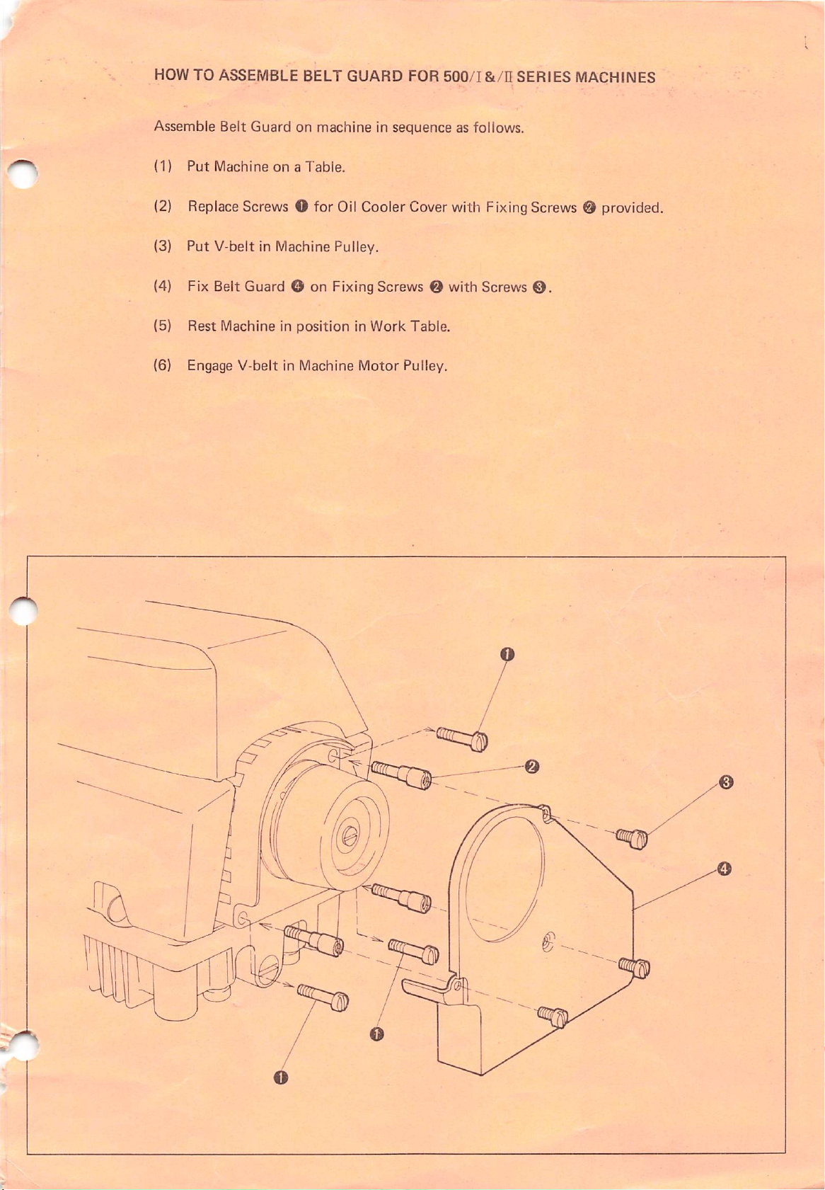
HOW TO ASSEMBLE BELT GUARD FOR
Assemble Belt Guard on machine in sequence as follows.
(1)
Put
Machineona
Table.
500/1
&/n
SERIES
MACHINES
(2) Replace Screws O for Oil Cooler Cover with FixingScrews 0 provided.
(3) Put V-belt in Machine Pulley.
(4) Fix Belt Guard O on Fixing Screws O with Screws
(5)
Rest
Machine in
(6) Engage V-belt in Machine Motor Pulley.
positioninWork
Table.
©.
Page 23

o
Cat.
No,
8082(023-410-026)
Printed in
Japan(0n781Tn5)
 Loading...