

Page 1

lUiLiLiGOX
&niBBS
DISASSEMBLY
&
ASSEMBLY
INSTRUCTIONS
♦
•• •'
. •
A.•.•
"t • . *
3
M.
D [if^
to
Page 2

lUiL.L.COX
Page 3
CONTENTS
NO
DISASSEMBLY
1
Oil
2
Belt
Cover
3 Top
4
5
6
7
8
9 Cloth
10
11
12 Needle
13
14 Diff.
15
16
17
18
19
20
21
22
23
24
25
26
27
28
29
30
31
32
33
34
35 Diff.
36
37 Diff.
38
39
Cover
Foot
Lift
Presser
Foot
Lift
Looper
Cover
Plate
Plate/Side
Fabric
Arm
Guard
(Left)
Thread
Diff.
Feed
Feed
Chainstitch
Bracket
Chainstitch
Needle
Top
Feed
Needle
Front
Front
Lower
Upper
Looper
Lower
Upper
Needle
Upper
Upper
Lower
Needle
Needle
Needle
Plate
Cover
Eccentric
Cover
Cover
Looper
Looper
Thread
Looper
Looper
Thread
Knife/Clamp
Knife
Knife/Holder
Cooler
Cooler
Guards/Bracket
Feed
Needle
Guards
Feed
Chainstitch
Movable
Page
(Complete)
Lever
Arm (Complete) 6
Shaft
Thread
Thumb
Guide
Cover
Takeup
Nut
(Rear)
(Complete) 7
(E32
E52)
Reg. Guide
Looper
Looper
Thread
Thread
Tension
Takeup
Plate
Cover
Guide
Thread
Thread
Guide
Thread
Holder
Guides
Clamp
Reservoir
Bracket
Takeup
Plate
Cover
Pin
Takeup
Guide
(E3
2) 12
Dog
(E52.
E56)
Dog
Looper/Holder
Needle
Guard
10
11
13
5
5
8
9
40
Lower
41
Upper
42 Main
43 Main
44
Needle
45
Oil
46
Oil
47
Upper
48
Needle
49
50
51
52
Needle
53
54
55
56
57
Needle
58
59
60
61
Oil
62
Main
63
By-Pass/Oil
64
Gear
65
Looper
66
67
68
Feed
69
70 Diff.
71
72
Feed
73
Looper
74
Housing
75
Bearing
76
Bearing
77
Looper
78
Feed
79
Feed
80
Feed
Looper/Lever
Looper
Feed
Dogs
Feed
Dog
Bracket
Crank
Pan
Distribution
Looper
Drive
Drive
Drive
Distributor/Lubrication
Feed
Pump/Oil
Shaft
Shaft
Feed
Crank
Avoiding
Clamp
Holder
(E32.
(E32.
(E56)
Crank
Splash
Screws
Reg.
-c
Screw
Felt
Guide
E52)
E52)
Screw
Screws
Indicator
Lever(Left)
Crank
Screw
Avoiding
Drive
Bar
Bar
Oil
Guide
Connection
Connection
Seal
left
Guide
Base
Block
13
14
15
16
•••17
18
19
20
21
Page 4
81
Feed
Drive
82 Looper Avoiding
83 Lower Looper Drive
84
85 Looper Avoiding
86
Lower
Looper
Lever
Shaft
Lever
Connection
Shaft/
Cap22
Connection
87 Upper Looper Drive Connection Cap
88 Upper Looper Drive Shaft/Connection
89 Balance Weight 24
90 Needle Drive Connection/Crank
91. Upper Knife Connection Cap
92 Machine Arm(Right)
93 Upper Knife Mechanism 25
94
Crankshaft
ASSEMBLY
1 Chainstitch Looper
Avoiding
(E32)
2
3
4 o
5
6
7
Crankshaft
8
9
10
11
12
13 Feed
14
15
Bars
❖
16 Feed Regulating Eccentric
17
18
Assembling
19
20
Feed
Eccentric
21
Feed Regulating Ratchet
22
Locating
23
24
Feed
Feed
Eccentric
Eccentric
25 Stitch Length/Housing
26
27
...
Shaft
.27
29
30
31
21
23
28 Stitch Length/Housing
29
30
'
31
Lower
32
33
34
35 Double
36
37
38
39
Balance
40
41
42
43
44
Upper
Needle
(E32.
Knife
E52)
45 Needle Drive Connection
28
46 Upper
47
48 Upper
49
50 Needle
51
52
53
Upper
54
55
Looper
Looper
Knife
•56 Machine Arm (Right)
57 Needle
58
59
60
61
Drive
62 Needle Holder Guide
63
64
65
66 Needle Drive Oil Supply Wick
(E32
67
68
69
E52)
Looper
Drive Connection••••••32
Chainstitch
Weight
Lever
Drive
Connection
Drive Connection
Drive
Drive
Shaft
Lever
(E32
^
Drive
Shaft(E32)
(E32.
{E56)
Shaft
(E56)
(E56)
E52)
Stud(E32
E52)
E52)
31
33
35
35
36
37
38
-39
40
Page 5
70
Needle
(E32
71
Needle
72 Oil
73
Drive
Oil
E52)
Arm
(E56) (E32 E52)
Distributors
Supply
Wick
114
40
115
41 116
117
Lower
Movable
Upper Looper
Looper
Needle
Setting
Guard
(E56)
(Rear)
50
51
74 Differential feed
75 // 119 Upper Looper Gauge
76
77
Feed Shaft 42
73
79 123
30
31
82 126
83
Gear
Pump/Oil
84
85
By-Pdss
86
87
Feed Bar
Guide
38
89
Differential
90 r, 131 Adjusting Needle Guard
91
92 Positioning Diff. Feed Crank
93 • '
94
Positioning
Lever
95 » 136
96
Upper
97
98 139
99 Main Feed Dog
100 Checking Needle
101
Needle
102
Needle
103
Needle
104 Needle Height
105 Needle Height
106
Needle
(E32
107
Needle
108
Lower Looper Lever (E32 E52)
109 Positioning Lower Looper
110 Lower Looper Setting
111
Positioning Lower Looper
112
Lower
113
Positioning
Looper
Alignment
(E56)
Plate
Thread
E52)
Plate 148 Upper & Lower Looper Thread Guides
Looper
Crank
'S'
❖
Indicator
-5-
Left/Oil Seal
❖
Feed
Regulating
❖
❖
Diff.
Feed Regulating
Guide
❖
Bracket
(E32
(E32 E52)
(E32
(E56)
Takeup
Setting (E32)
Lower
Base
E52)
E52)
(E52)
Looper
Guide
Guide
(E52)
•••••
(E32)
(E56)
118
120
121
Double
122
Positioning
Double
124
Needle Guard Bracket 53
125
Adjusting
43
127
Adjusting
(Front) (E32)
128
Adjusting
(£32)
129"
Needle
130
Adjusting
•••44
45 135 Positioning Main Feed Dogs
46 141
47 145
48
— 49 150
•••50
(E52 E56)
(Front) (E52
132
Feed
133 Needle Plate 55
134
Maximum
Feed
137
Oil
138 Needle Cooler Reservoir (Lower)
Lower
140 '''
142
Upper
143
144
146
147
Upper Looper Holder Cover
(E32
149 '''
151
152
Upper
(E56)
Chainstitch Looper
Double
Chainstitch Looper Setting
Needle
Needle
Chainstitch Looper
Guard
Guard
Chainstitch
Guard
Dogs
Dog Height
Pan
Knife
Knife
(E52 E56)
Needle
Stitch Length
Guard (Rear)
E56)
Holder
E52)
Looper
Holder
Holder
(Rear) (E32)
Needle
Guard
; -
Cover
••••52
54
56
57
58
39
Page 6
153 Upper &
Guides
154
155
156
157
158
Needle
159
Feed
160
Cover
161 Machine
162
Fabric
163
Needle
164
Lower
(E56)
Plate
Eccentric
Plate
Arm
Guard
Thread
Looper
Cover
(Left)
Guides
(E32
(E32
Thread
E52)
E52)
59
60
•••61
165 "
166
Needle
167
168
Chainstitch
Bracket
169
Stopper
170 Chainstitch Looper
Thread
Looper
(E32)
(E32)
Guides
Thread
Thread
(E56)
Guide
62
Takeup
(E32)
171
172
173
174
175
176
177
178
179
180
181
182
183
184
Chainstitch
(E32)
Chainstitch
Bracket
Presser
Foot
Lift
Chainstitch
(E32)
Cover
Cloth
Front
Belt
Plate
Cover
(E32)
Arm-
Plate.
Cover
Looper
Looper
Lever
Looper
Thread
Thread
Thread
Eyelets
Tension
63
64
Guide
65
185 Replacing Oil •••• 66
186
Top
Cover
187
Lubrication
188
189
190
191
192
193
Threading
Threading
(E52)
(E5
6)
67
68
194
Threading
195
Threading
196
Threading
197
198 Needle
199
Looper
200
Needle
201
Looper
202
Needle
203
Looper
204
Chainstitch
Control
205
Stitch
206
Differential
207
Feed
208 Auxiliary
209
210
Presser
211
Presser
212 Needle
(E32
213
Sharpening
214 Oil
Filter
215 Changing
OLD
216
Standard
217 Needle Height
218
Lower
219 Upper Looper
220 Double Chainstitch
221
Threading (E52) 81
222
223 Threading
224 Threading
225
Threading
226
Threading
227
Needle
Looper
228
229
Needle
230
Looper
(E56)
(E32)
(E3
2) 70
ADJUSTMENTS
Thread
Thread
Thread
Thread
Thread
Thread
Control
Control
Control
Control
Control
Control
Looper
(E52)
(E52)
(ESS)
(ESS)
(E32)
(E32)
Thread
(E32)
Length Adjustment
Feed
Dog
Tilt
Feed
Ratio
Dog Height
Adjustment
(E32)
Foot
Lift
Adjustment
Foot
Alignment
Holder
E52)
Replacement
'•
Knives
Inspection
Differential
TYPE
MACHINES
Feed
Adjustments 79
(E32
Looper
(E32
(E32
E52)
ES2)
ES2)
Looper
(E5
2) 82
(E32)
(E32)
(E32)
Thread
Thread
Thread
Thread
Control
Control
Control
Control
(E52)
(ES2)
(E32)
(E32)
•.^•71
•^••72
(ES2
E56)
Capacity
(E32)
; 83
69
73
74
7S
76
77
78
80
84
85
Page 7
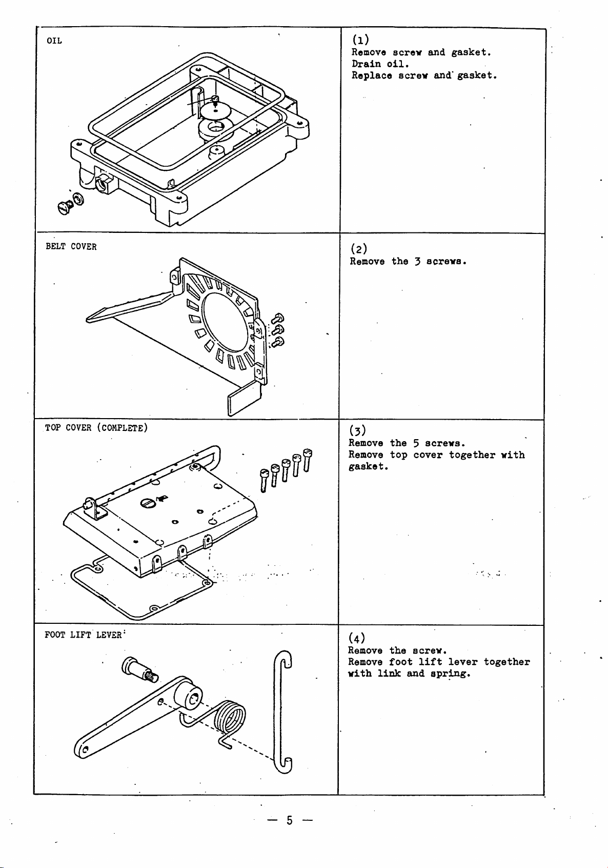
OIL
BELT
COVER
(i)
Remove
Drain
Replace
(2)
Remove
screv
oil.
the
screv
5
and
and'
screva.
gasket.
gasket.
TOP
FOOT
COVER
LIFT
(complete)
LEVER'
fd
(5)
Remove
Remove
gasket.
(4)
Remove
Remove
vith
link
the
top
the
foot
5
cover
screv.
and
screvs.
lift
together
lever
spring.
vith
together
- 5 -
Page 8
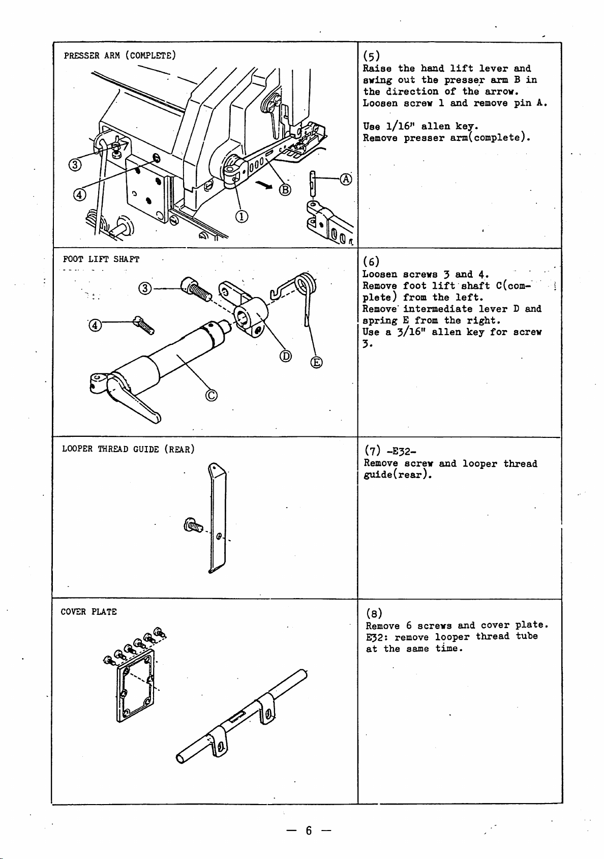
PRESSBR
(D
POOT
LIFT
•®
ARM
(COMPLETE)
SHAFT
(5)
Raise
aving
the
Loosen
Use
Remove
the
out
direction
screw
1/I6"
presser
hand
lift
the
presser
of
the
1
and
alien
key.
arm(complete).
lever
armBin
arrow.
remove
and
pin
A.
(6)
Loosen
Remove
plete)
Remove'
\
spring
Use
3.
screws
foot
from
intermediate
E
from
a 3/16"
3
lift
the
the
alien
and
shaft
left.
right.
key
4.
lever
c(com
for
B
and
screw
LOOPER
COVER
THREAD
PLATE
GUIDE
(REAR)
(7)
-E32-
Remove
screw
guide(rear).
(8)
Remove6screws
Ei32j
remove
at
the
same
and
looper
time.
looper
and
cover
thread
thread
plate.
tube
- 6 -
Page 9
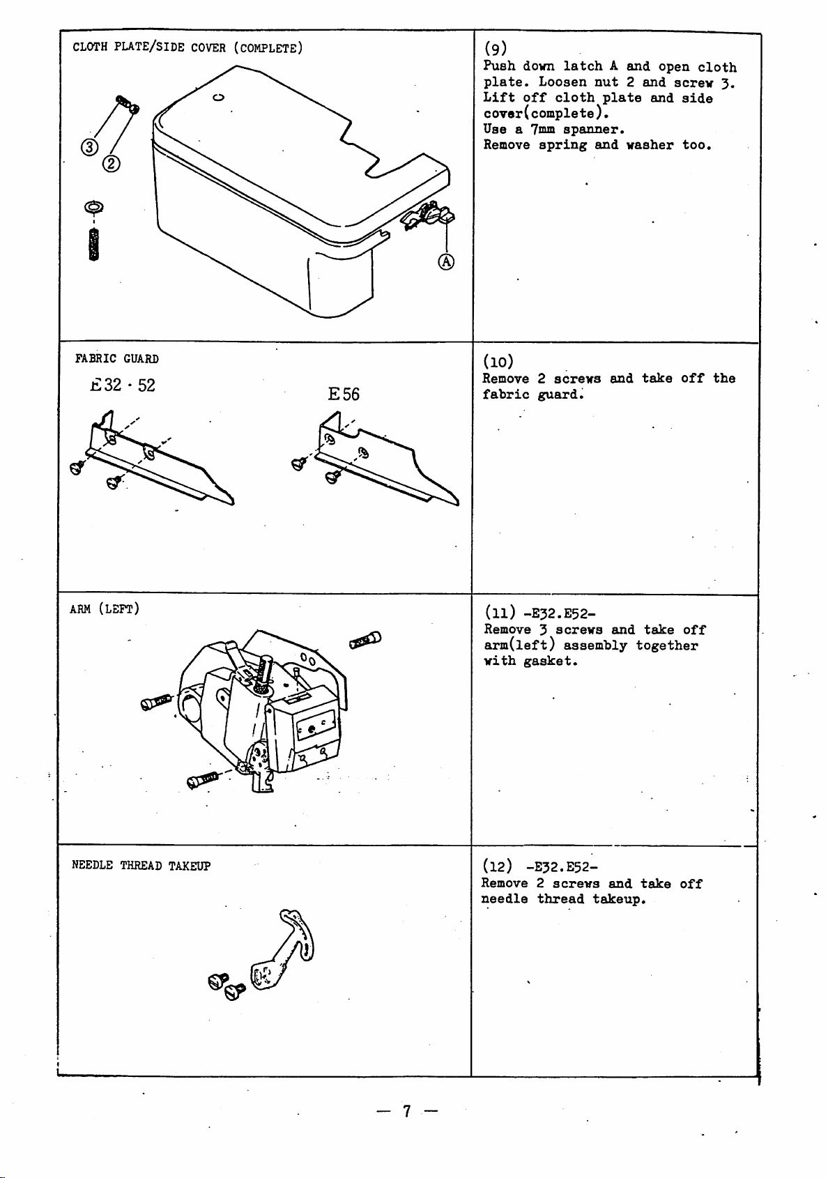
CLOTH
plate/side
COVER
(COMPLETE)
(9)
Push
down
latch
plate.
Lift
Loosen
off
nut
cloth
cover(complete).
Usea7mm
Remove
spanner.
spring
and
A
plate
and
2
and
and
washer
open
screw
cloth
3.
side
too.
FABRIC
£32•52
ARM
(left)
GUARD
E56
(lO)
Remove
fabric
(ll)
Remove3screws
arm(left)
with
2
screws
guard.
-E32.E52-
assembly
gasket.
and
and
take
off
take
off
together
the
NEEDLE THREAD TAKEUP
- 7 -
(12) -E32.E52-
Remove
needle
2
screws
thread
and
takeup.
take
off
Page 10
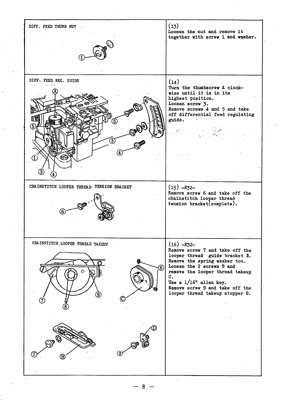
DIFF.
FEED
THUMB NUT -
Cl
©
(13)
Loosen
together
the
vith
nut
and
screw
remove
1
and
it
washer.
DIFF.
CHA.INSTITCH LOOPER
FEED
REG.
GUIDE
THREAD
TENSION
BRACKET
(14)
Turn
the
wise
\intil
highest
Loosen
Remove
off
differential
guide.
(15)
-E32-
Remove
chainstitch
tension
thimbscrew
it
is
A
clock
in
its
position.
screw
screws
screw
4
6
looper
and5and
feed
and
take
thread
regulating
hracket(complete).
off
take
the
CHAINSTITCH
LOOPER
THREAD
TAKEUP
(16)
-E32-
Remove
looper
Remove
Loosen
remove
C.
screw
thread
the
the
the
Use a 1/16"
Remove
looper
screw
thread
7
spring
2
screws
looper
alien
9
takeup
and
guide
and
take
"bracket
washer
8
thread
key.
take
stopper
and
off
too.
takeup
off
the
B.
the
D.
- 8 -
Page 11
NEEDLE
TOP
COVER
PUTE
PLATE
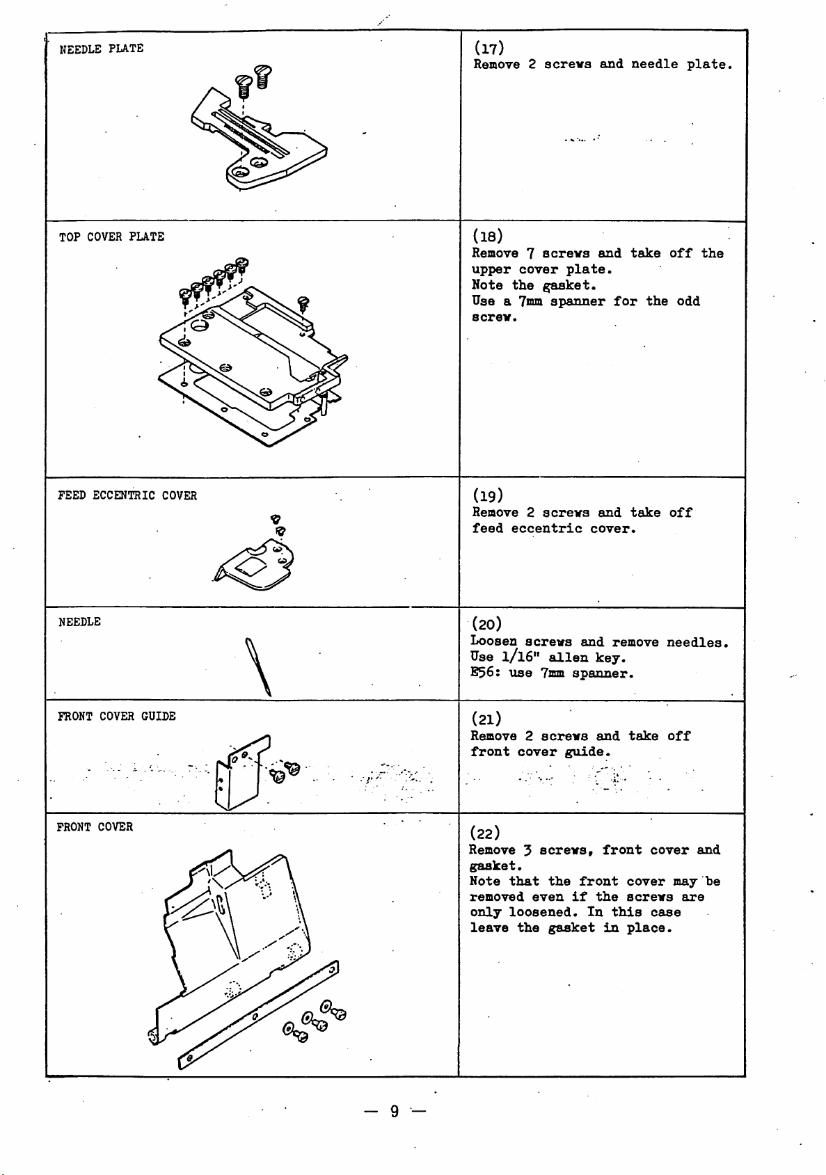
(17)
Remove2screva
(18)
Remove7acrevs
upper
Note
Usea7mm
screv.
cover
the
plate.
gasket.
spanner
and
and
for
needle
take
the
off
plate.
the
odd
FEED
NEEDLE
FRONT
FRONT
ECCENTRIC
COVER
COVER
GUIDE
COVER
(19)
Remove
feed
2
acreva
eccentric
(20)
Loosen
Use
S36:
screws
1/I6"
use
alien
7mm
(21)
Remove
front
2
cover
screws
guide.
(22)
Remove5screws,
gasket.
Note
that
the
removed
only
leave
even
loosened.
the
gasket
and
cover.
and
remove
key.
spanner.
and
front
front
if
the
In
this
in
take
take
cover
screws
place.
off
needles,
off
cover
case
may
are
and
be
- 9 -
Page 12
LOWER
LOOPER
THREAD
E32•52
TAKEUP
E56
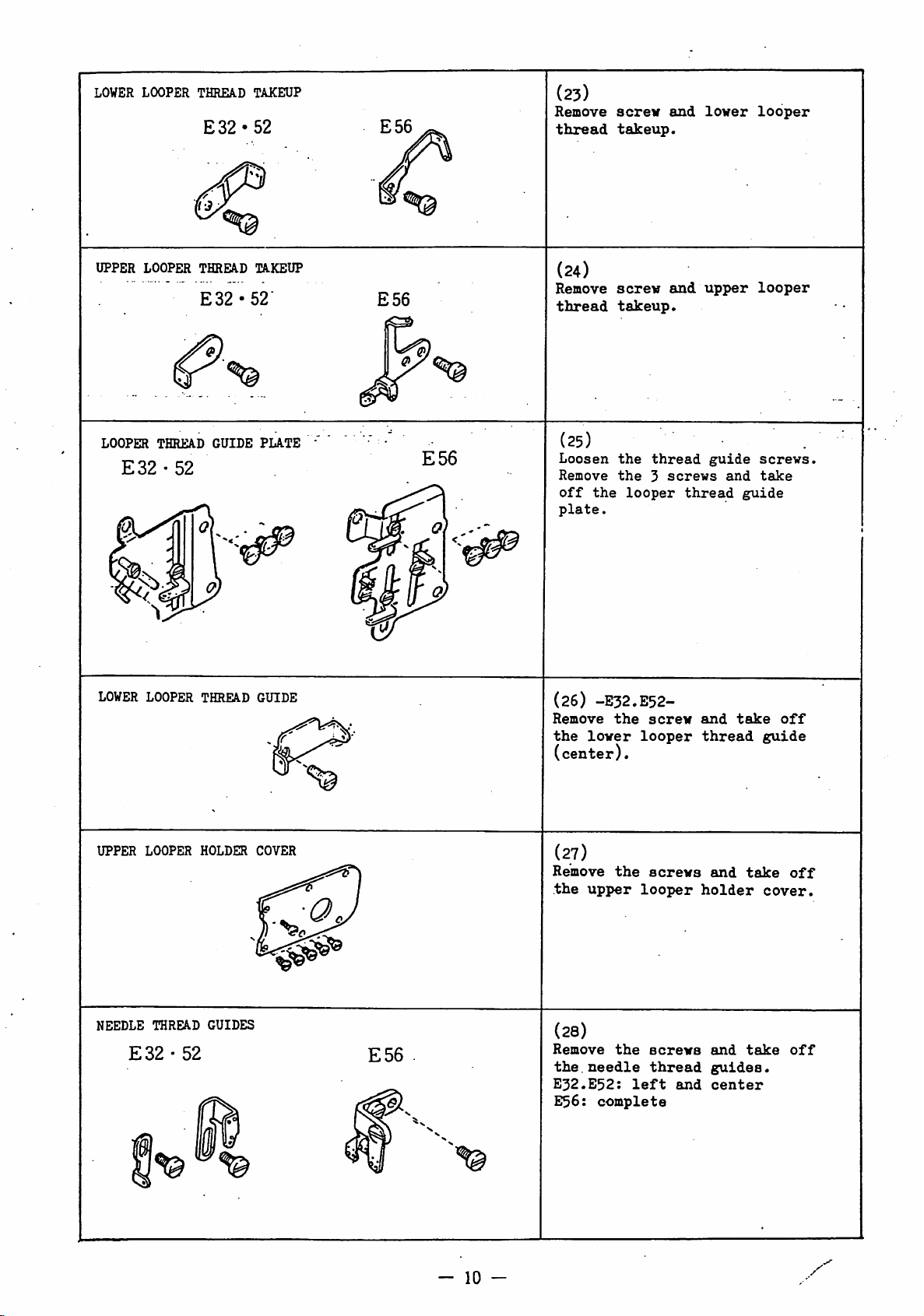
(23)
Remove
thread
screw
takeup.
and
lower
looper
UPPER
LOOPER
E32-52
LOWER
LOOPER
THREAD
LOOPER
THREAD
TAKEUP
E32-52"
GUIDE
THREAD
GUIDE
PLATE
E56
E56
(24)
Remove
thread
(25)
Loosen
Remove
off
the
plate.
(26)
-E32.E52-
Remove
the
lower
(center).
screw
takeup.
the
the
looper
the
looper
and
thread
3
screws
screw
upper
guide
thread
and
thread
and
guide
take
looper
screws.
take
off
guide
UPPER
NEEDLE
LOOPER
THREAD
E32•52
HOLDER
GUIDES
COVER
E56
(27)
Remove
the
upper
the
looper
(28)
Remove
the.
E32.E52:
E56:
-
10
-
the
needle
left
complete
screws
screws
thread
and
and
holder
and
guides.
center
take
take
off
cover.
off
Page 13
UPPER
knife/clamp
1^
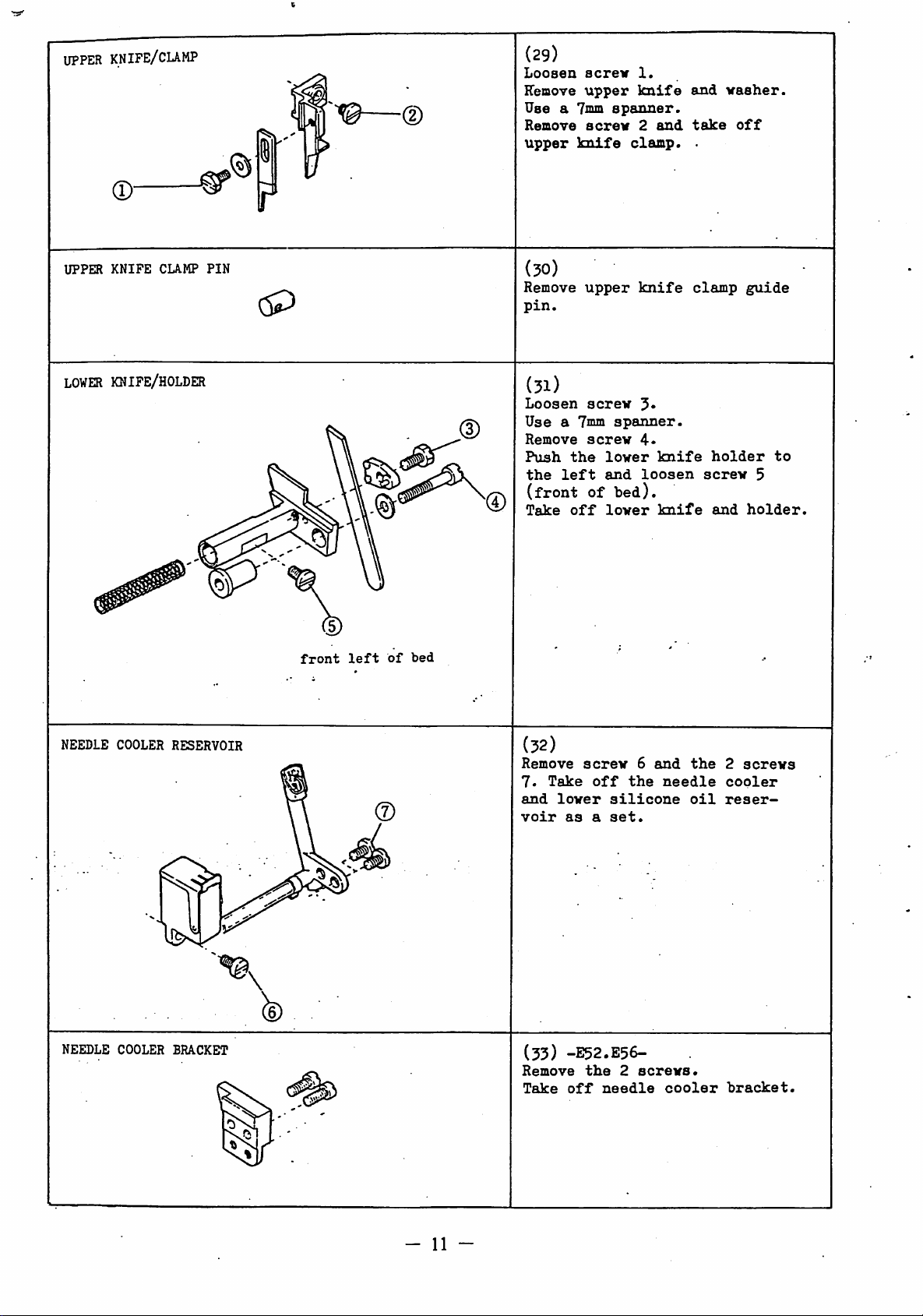
(29)
Loosen
Remove
Use
Remove
upper
acrev
upper
a 7mm
screw
knife
1.
knife
spanner.
2
clamp.
and
and
take
.
vasher.
off
r
UPPER
LOWER
KNIFE
CUMP
KNIFE/HOLDER
PIN
front
left
(30)
Remove
pin.
upper
knife
clamp
guide
(31)
Loosen
Use
Remove
Push
the
(front
Take
of
bed
screw
a 7mm
screw
the
left
of
off
spanner.
lower
and
bed).
lower
4.
knife
loosen
knife
holder
screw
and
to
5
holder.
NEEDLE COOLER
NEEDLE
COOLER
RESERVOIR
BRACKET
(32)
Remove
7.
Take
and
lower
voir
(33)
Remove
Take
screw
off
silicone
as
a
set.
-J52.E56-
the
2
off
needle
6
the
screws.
and
needle
cooler
the
oil
2
screws
copier
reser
bracket.
- 11 -
Page 14
NEEDLE
GUARDS/BBAOKET
(E32)
Q
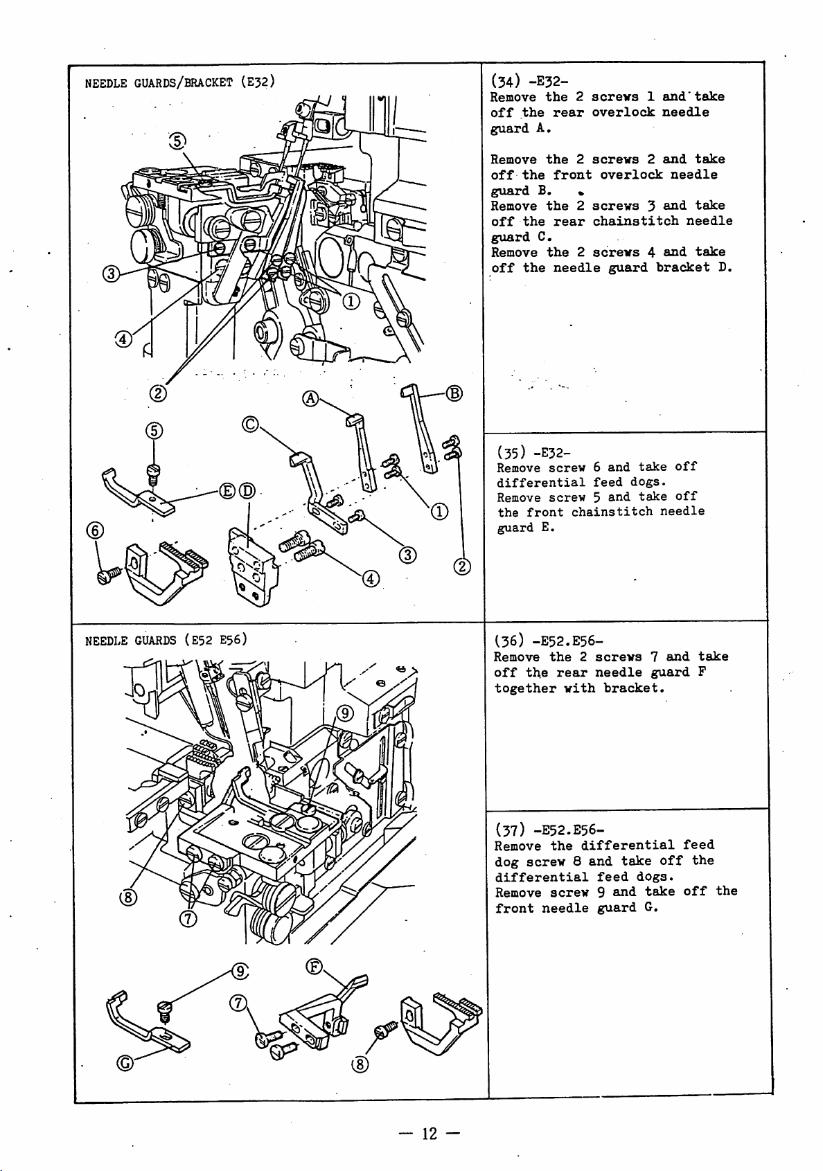
(34)
Remove
off
guard
-E32-
the
A.
the
rear
2
screirs
overlook
1
and'take
needle
(D
d)®
n
Remove
off
the
guard
Remove
off
the
guard
Remove
off
the
(35)
Remove
differential
Remove
the
front
guard
the
2
front
B. »
the
2
rear
C.
the
2
needle
-E32-
screw6and
screw
chainstitch
E.
screws
overlook
screws
chainstitoh
screws
guard
feed
dogs.
5
and
2
3
4
take
take
and
needle
and
needle
and
bracket
off
off
needle
take
take
take
D.
NEEDLE
GUARDS
(E52 E56)
(36)
-E52.E56-
Remove
off
the
together
(37)
-E52.E56-
Remove
dog
screw8and
differential
Remove
front
the
rear
with
the
screw
needle
2
screws
needle
bracket.
differential
take
feed
9
and
guard
7
guard
dogs.
take
G.
and
off
feed
the
off
take
P
the
-
12
-
Page 15
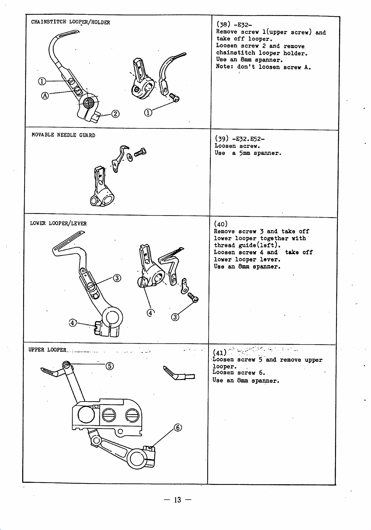
CHAINSTITCH
L00PE21/H0LDER
(58)
-E32-
Remove
take
off
Loosen
chainstitch
Use
an
Smm
Note:
don't
screw
1(upper
looper.
screw2and
looper
spanner.
loosen
screw) and
remove.
holder.
screw
A.
MOVABLE NEEDLE GUARD
LOWER
LOOPER/LEVER
(59)
Loosen
Use
(40)
Remove
lower
thread
Loosen
lower
Use
an
-E32.E52-.
screw.
a 3mm
spanner.
screw
looper
guide(left).
screw
looper
Smm
spanner.
3
and
together
4
and
lever.
take
take
off
with
off
UPPER
LOOPER.
-
13
-
(4i)
" " : ; • •
Loosen
looper.
Loosen
Use
screw5and
.
screw
an
Smm
6.
spanner.
•'
remove
upper
Page 16
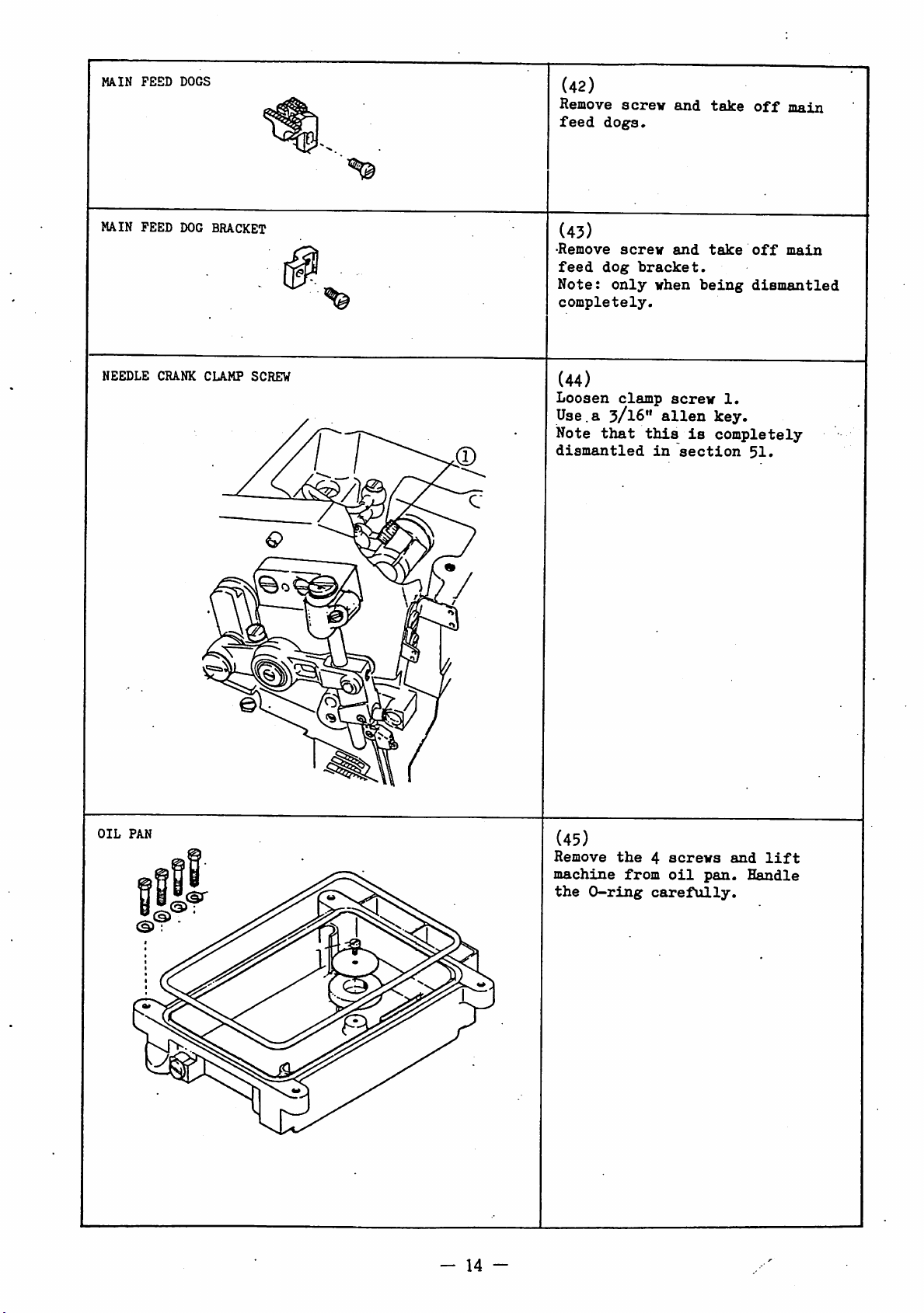
MAIN
FEED
DOGS
(42)
Remove
feed
screw
dog:s*
and
take
off
main
MAIN FEED
NEEDLE
CRANK
DOG
BRACKET
CLAMP
SCREW
€>
(43)
•Remove
feed
Note:
completely.
dog
only
screw
bracket.
(44)
Loosen
clamp
Use.a 3/16"
Note
that
dismantled
when
this
in
and
screw
alien
is
section
take
off
being
dismantled
1.
key.
completely
51.
main
OIL
PAN
(45)
Remove
machine
the
-
14
-
the
O-ring
from
4
screws
oil
carefully.
pan.
and
Handle
lift
Page 17
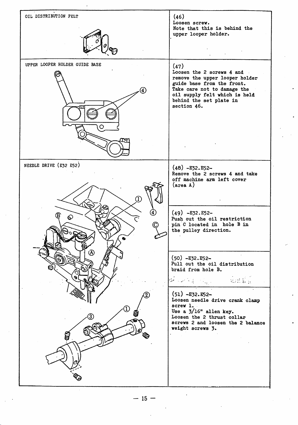
OIL
DISTRIBUTION
FELT
(46)
Loosen
Note
upper
screv.
that
looper
this
is
holder.
behind
the
UPPER
NEEDLE
LOOPER
DRIVE
HOLDER
(E32 E52)
GUIDE
BASE
(47)
Loosen
remove
guide
Take
oil
behind
section
(48)
Remove
off
(area
the
the
base
care
not
supply
the
46.
-E32.E52-
the
machine
A)
2
screws
upper
from
felt
set
2
screws
arm
to
plate
looper
the
damage
which
left
4
and
front.
is
in
4
and
cover
holder
the
held
take
(49)
-E32.E52-
Push
out
the
pin
C
located
the
(50)
Pull
braid
pulley
-E32.E52-
out
from
direction.
the
hole
(51) -E32.E52-
Loosen
screw
needle
1.
Usea3/I6"
Loosen
screws
weight
the
2
and
screws
2
oil
in
oil
drive
alien
thrust
loosen
3»
restriction
hole
distribution
B.
crank
key.
collar
the
B
in
2
clamp
balance
-
15
-
Page 18
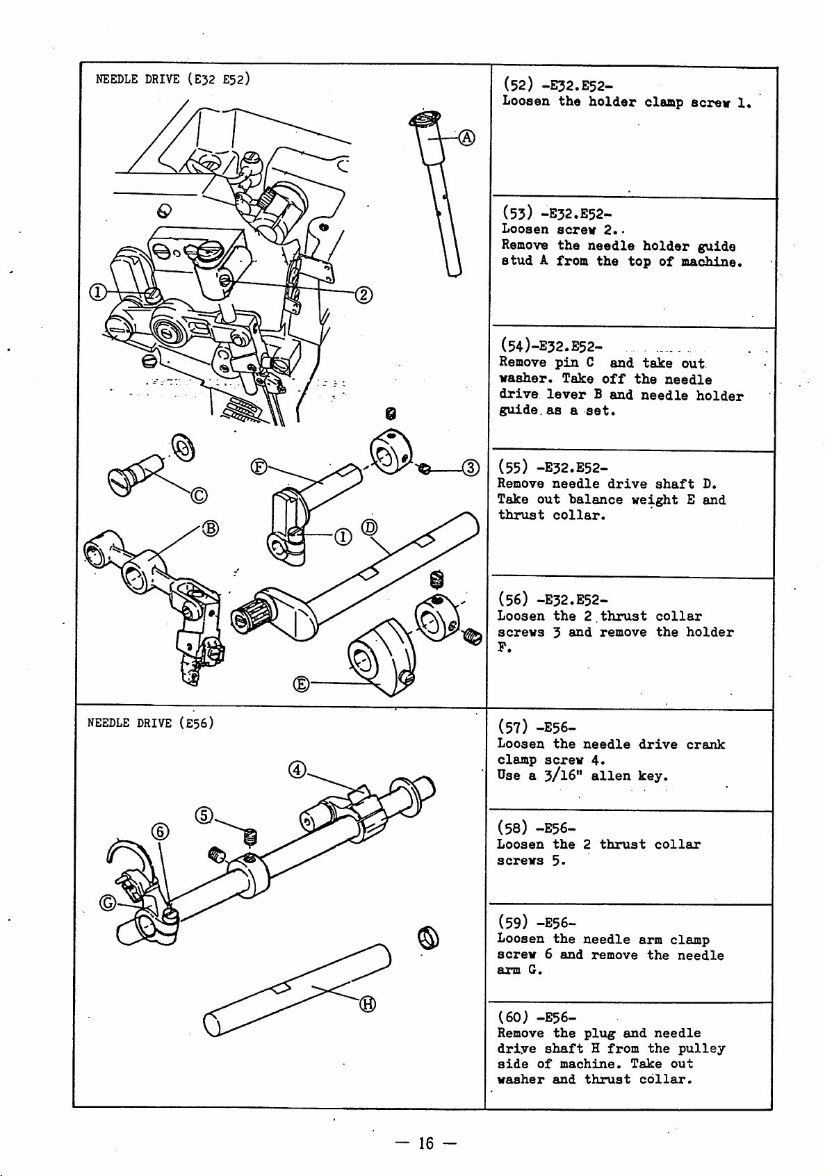
NEEDLE
DRIVE
(E32 E52)
(52) -E32.E52-
Loosen
the
holder
(53) -E32.E52-
Loosen
Remove
stud
A
screv
the
from
needle
(54)-E32.E52-
Remove
washer.
drive
guide,
pin
C
Take
lever
asaset.
(55) -E32.E52-
Remove
Take
thrust
out
needle
balance
collar.
the
B
2.•
and
off
and
drive
claap
holder
top
take
the
needle
weight
of
needle
shaft
screv
guide
machine.
out
holder
D.
E
and
1.
NEEDLE
DRIVE
(E56)
(56) -E32.E52-
Loosen
screws
P.
(57)
Loosen
clamp
Use
(58)
Loosen
screws
(59)
Loosen
screw
arm
the
3
and
-E56-
the
screw
a 3/16"
-E56-
the
5-
-E56-
the
6
and
G.
2
needle
4*
alien
2
needle
remove
thrust
remove
thrust
collar
drive
key.
collar
arm
the
the
clamp
holder
crank
needle
(60)
-E56-
Remove
drive
side
washer
-
16
-
shaft
of
the
machine.
euid
plug
H
thrust
from
and
Take
needle
the
collar.
pulley
out
Page 19
OIL
distributor/lubrication
MAIN
FEED
CRANK
SCREW
block
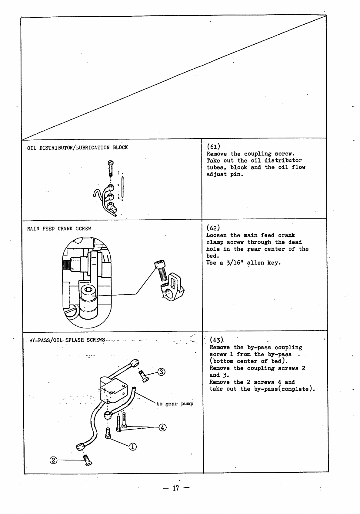
(61)
Remove
Take
tubes,
adjust
(62)
Loosen
clamp
hole
bed.
Use a
the
out
block
pin.
the
screw
in
3/16"
the
the
coupling
oil
and
main
through
rear
alien
screw.
distributor
the
feed
the
center
key.
oil
crank
flow
dead
of
the
BY-PASS/OIL
SPLASH
SCREWS
-
to
gear
pump
-
1?
-
(63)
Remove
screw
(bottom
Remove
and
3«
Remove
take
out
the
1
from
center
the
the
by-pass
coupling
2
the
coupling
the
of
screws
by-pass
bed).
screws
4
.
2
and
by-pass(complete)
Page 20

GEAR
PUMP/OIL
0-ring
INDICATOR
%==KD
(64)
Remove
out
the
Note
the
Remove
indicator
indicator.
the2screws
gear
pump.
0-ring,
the2screws
support
and
1
2,
and
the
the
take
oil
oil
LOOPER
SHAFT
SCREWS
(65)
Remove
screw
the
3
together
washers. (The
right,
on
Use a
the
angles
pulley
7mm
spanner.
(66)
Remove
screw
washers.
center
(67)
Loosen
the
(The
the
the
4
together
(The
of
the
-E32-
the
nut
chainstitch
shaft
bed).
is
upper
shaft
to
side.)
lower
shaft
bed.)
on the
looper
with
the
looper
with
5 on
looper
shaft
the
2
is
at
crankshaft
-
shaft
the
2
is
in
the
the
end
shaft.
left
of
of
FEED
SHAFT
(68)
Loosen
clamp
drive
(The
machine
the
screw
crank
shaft
and
crankshaft)..
Usea3/I6"
(69)
Loosen
screws
shaft
from
-
18
-
the
8
A
the
and
together
left
diff.
6
clamp
at
parallel
alien
2
thrust
remove
the
of
and
feed
screw
rear
key.
with
the
crank
the
to
collar
the
cap
machine.
feed
7.
of
the
feed
the
Page 21
DIFF.
feed
feed
cranks
REG.
LEVER
(LEFT)
©
©
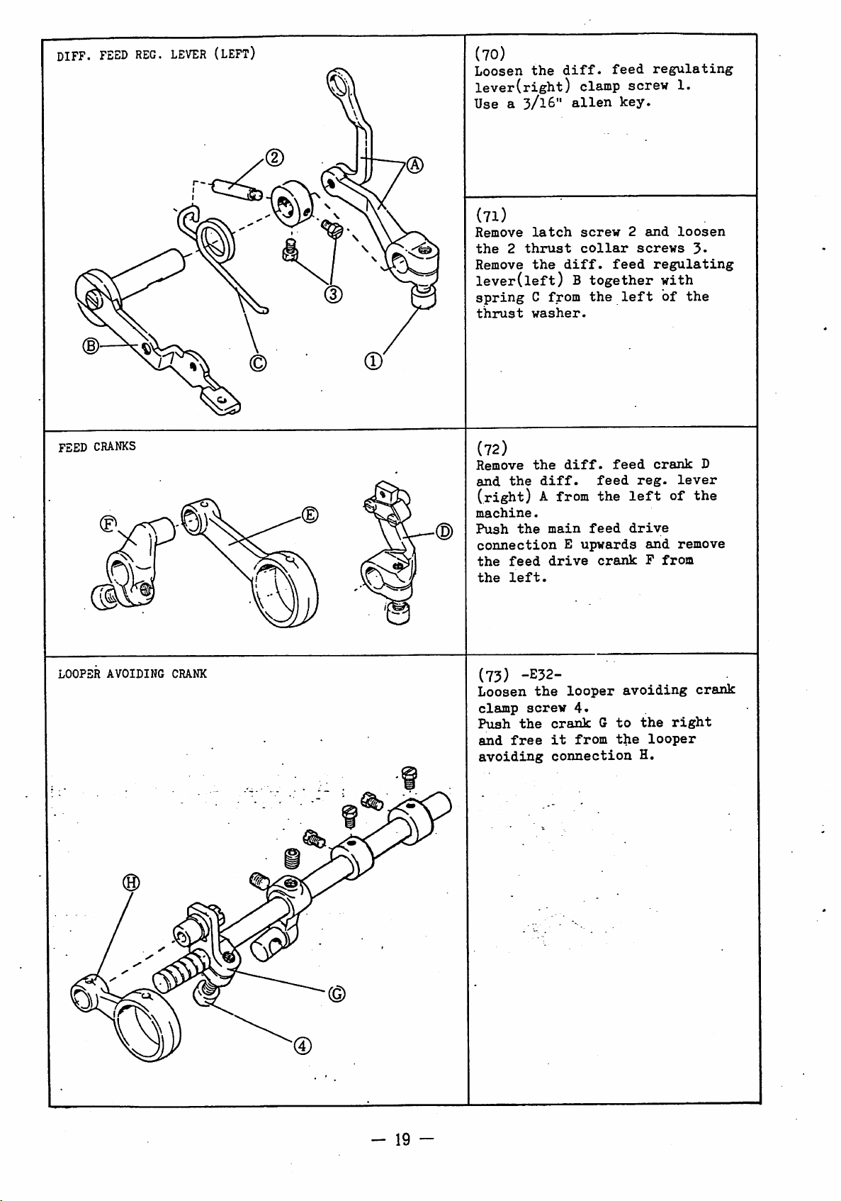
(70)
Loosen
the
lever(right)
Use a
(71)
Remove
the
Remove
2
3/16"
latch
thrust
the
lever(left)
spring
thrust
C
from
washer.
(72)
Remove
and
(right)
machine.
Push
connection
the
the
the
the
feed
left.
the
diff.
A from
main
drive
diff.
feed
clamp screw 1.
alien
diff.
B
diff.
E
screw
collar
feed
together
the
feed
feed
the
feed
upwards
crank
key.
2
screws
left
reg.
left
drive
regulating
and
loosen
regulating
with
of
crank
lever
of
and
remove
P
from
3«
the
D
the
loopsr
avoiding
crank
(73)
Loosen
clamp
Push
the
and
free
avoiding
-E32-
the
screw
looper
4.
crank
it
G
from
connection
avoiding
to
the
the
looper
H.
crank
right
-
19
Page 22
HOUCIIIC
E32
E52•E56
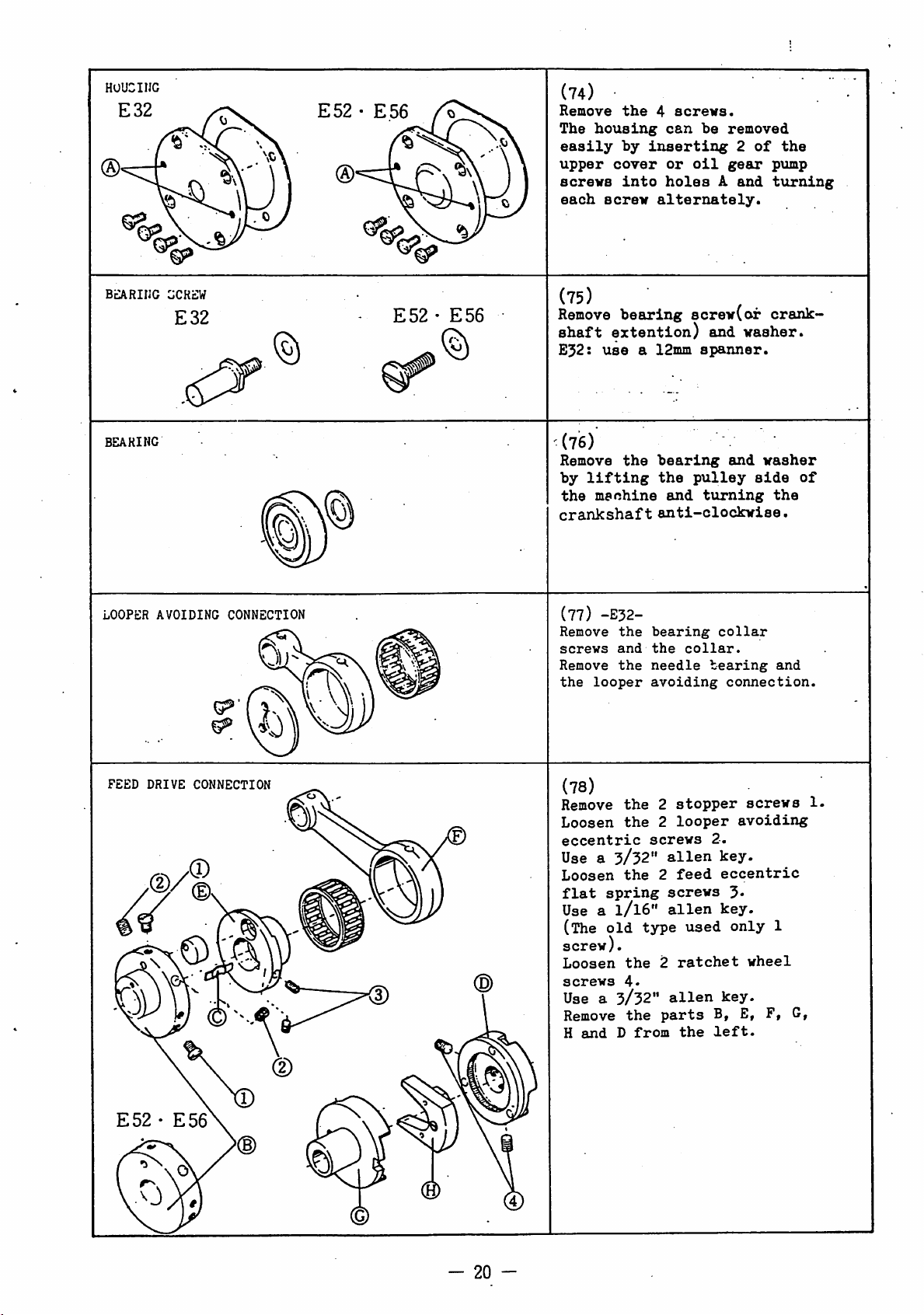
(74)
Remove
The
easily
upper
screws
each
the
housing
by
cover
into
screw
4
screws.
can
inserting
or
oil
holes
alternately.
be
removed
2
gear
A
and
of
pump
t\irning
the
BlARIIJC
BEARING
LOOPER
gcrsw
E32
AVOIDING
CONNECTION
E52•E56
(75)
Remove
shaft
E32:
extention)
use
(76)
Remove
by
lifting
the
machine
crankshaft
(77)
-E32-
Remove
screws
Remove
the
looper
bearing
a 12inm
the
bearing
the
anti-clockwise.
the
bearing
and
the
the
needle
avoiding
screw(or
pulley
and
collar.
and
spanner.
and
tiirning
collar
bearing
connection.
crank
washer.
washer
side
the
and
of
FEED
DRIVE
E52-E56
CONNECTION
(D
(78)
Remove
Loosen
eccentric
Use a
Loosen
flat
Use a
(The
screw).
Loosen
screws
Use a
Remove
H
and
the2stopper
the
2
looper
screws
3/52"
spring
1/I6"
old
3/32"
D
the
the
4.
the
type
from
alien
2
feed
screws
alien
2
ratchet
alien
parts
the
used
avoiding
2.
key.
eccentric
3-
key.
only
key.
B, E,
left.
screws
1
wheel
F,
1.
G,
20
Page 23

FEED BAR
FEED
BAR
FEED
DRIVE
OIL
SEA,L GUIDE
GUIDE
LEFT
® ^
(79)
Remove
Move
position
seal
the
feed
guide.
(80)
Remove
feed
the
base
(81)
Loosen
the
and remove
plete)
Remove
feed
D
the
and
.
main
bar
main
left
4
screws.
bars
to
and
take
2
screws
guide(left).
feed
bar
feed
bar
feed
C,
feed
feed
crank
of
the
machine.
bar
bar
their
off
and
pin
pin
the
B,
lift
E
highest
oil
take
screw
A (com
diff.
block
from
off
1
LOOPER
AVOIDING
LEVER
©
(82)-E32^-
Loosen
shaft
Loosen
lev^r
the2iboper
thrust
the2looper
screws
Use a 1/8"
collar
4-
alien
key.
-
avoiding
screws
avoiding
3.
-
21
-
Page 24

LOWER
LOOPER
DRIVE
CONNECTION
CAP
(85)
Remove
cap
from
Note:
together
-E52.E56-
the2cap
the
keep
the
asaset.
top
cap
screvs
center
and
and
of
bed.
connection
LOWER
CHAINSTITCH LOOPER
LOOPER DRIVE CONNECTION CAP
©
DRIVE
SHAFT
(84)
Remove
the
top
bed.
Prom
machine
avoiding
Remove
collar
Loosen
screw
shaft
Take
Use a
-E32-
the
center
the
bed
the
A.
looper
4
and
D.
out
3/16"
2
bottom
loosen
block
nut
remove
washer
alien
cap
drive
acrews
of
rear
collar
5
together
C.
the
the
crank
looper
key.
1
machine
of
the
lobper
screw
from
2.
with
clamp
drive
LOOPER
AVOIDING
SHAFT
22
(85)
-E32-
Loosen
screws
Remove
together
avoiding
avoiding
'the
-
2
the
1.
the
the
lever
crank
thrust
2
shaft
thrust
plug,
E,
P,
collars.
from
looper
looper
shaft
collar
the
left
U
and
Page 25
LOWER
E32
LOOPER
LEVER
SHAPT/CONNECTION
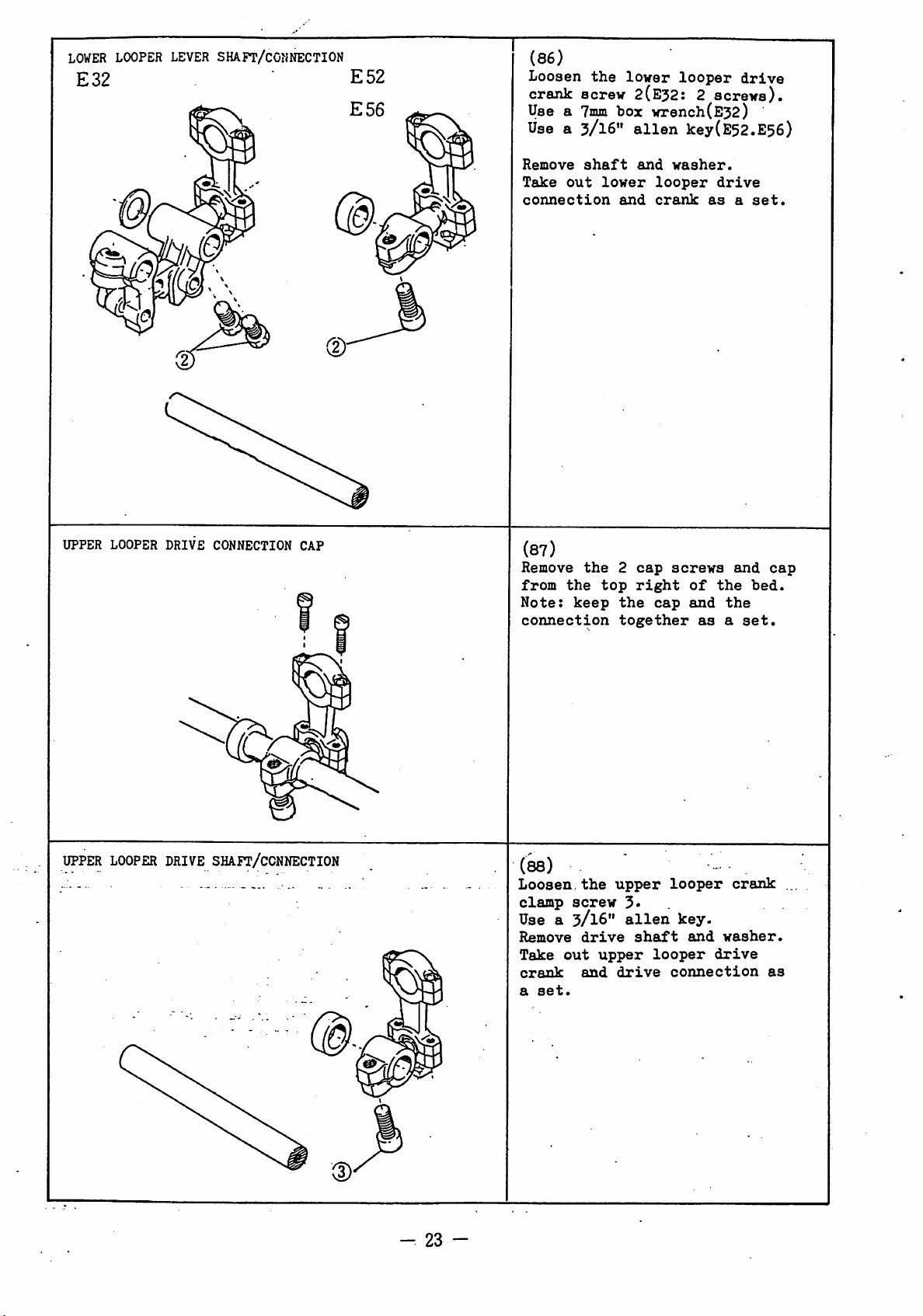
(86)
Loosen
the
lower
looper
crank screw 2(E52: 2
Use a
Use
Trnin
a 3/16"
box wrench(E32)
alien
key(E52.E56)
drive
screws).
UPPER
LOOPER
DRIVE
CONNECTION
CAP
Remove
Take
out
connection
(87)
Remove
from
the
Note:
connection
keep
shaft
the
lower
and
2
top
the
together
and
cap
right
washer.
looper
crank
screws
cap
drive
as
of
the
and
the
asaset.
a
and
set.
cap
bed.
UPPER
LOOPER
DRIVE
SHAFT/CCNNECTION
(88)
Loosen.the
clamp
Use a
Remove
Take
out
crank
a
set.
-
23
-
screw
3/16"
drive
upper
and
upper
3« .
alien
shaft
drive
looper
key.
looper
connection
and
crank
washer.
drive
as
Page 26
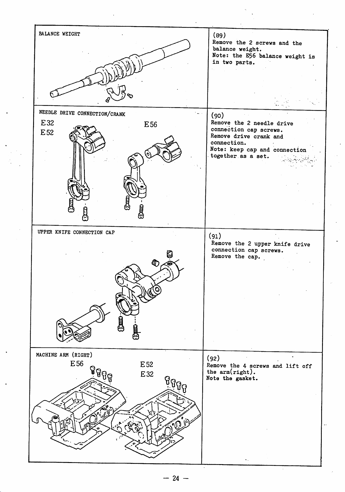
BALANCE WEIGHT
(89)
Remove
balance
Note:
in
two
the
weight.
the
parts.
2
E56
screws
balance
and
weight
the
is
NEEDLE
E32
E52
UPPER
KNIFE
DRIVE
CONNECTION/CRANK
CONNECTION CAP
E56
(90)
Remove
connection
Remove
connection.
Note:
together
(91)
Remove
connection
Remove
the
2
needle
cap
drive
keep
as
crank
cap
a
the2upper
cap
the
cap.
screws.
and
set.
screws.
drive
and
connection
•
knife
drive
MACHINE
ARM
(RIGHT)
E56
(92)
Remove
the
Note
-
24
-
the
arm(right).
the
gasket.
4
screws
and
lift
off
Page 27
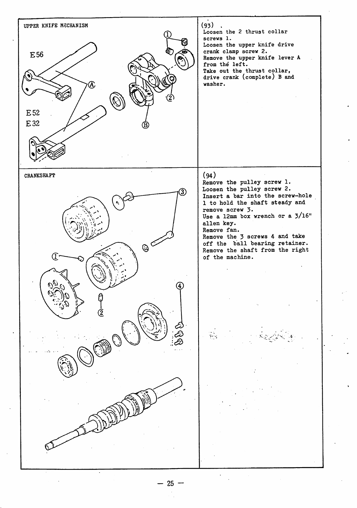
UPPER
KNIFE
MECHANISM
(93)
Loosen
screws
Loosen
crank
Remove
from
Take
drive
washer.
.
the
2
clamp
the
out
1.
the
the
left.
the
thrust
upper
screw
upper
thrust
knife
2.
knife
collar
drive
lever
collar,
crank (complete) B and
A
CRANKSHAFT
(94)
Remove
Loosen
Insert
1
to
remove
Use a
alien
Remove
Remove
off
Remove
of
the
hold
the
the
the
a
bar
screw
12mm
key.
fan.
the
ball
the
machine.
pulley
pulley
into
the
shaft
5*
box wrench
3
screws
bearing
shaft
from
screw
screw
the
screw-hole
steady
ora3/I6"
4
and
retainer.
the
1.
2.
and
take
right
-
25
-
Page 28

ASSEMBLY
—
26
-
Page 29

CHAINSTITCH
LOOPER
AVOIDING SHAFT
(l)
- E32 -
Insert
A
into
Replace
looper
collar
the
the
the
avoiding
E
right)
looper
bed
looper
(polished
and
avoiding
through
avoiding
lever
surface
thrust
(polished surface to the
on
the
shaft.
hole
crank
D,
thrust
collar
left)
shaft
B.
C,
to
P
1
i.' j.. ,
0pot
Bcr^v
(2)
- E52 -
Replace
(3)
- E32 -
Maintaining
cap
G,
push
left.
collar
the
screw
(4) -
Push
to
P
in
screws
first.
so
2
the
the
Lightly
F
screws
first.
E32
the
right,
that
2.
cap
to
thrust
shaft
G
in
a
small
the
push
the
1.
-
hold
there
and
Tighten
the
gap
shaft
the
left
Tighten
collar
thrust
i s
no
tighten
the
bushing.
with
to
the
thrust
and
tighten
the
E
lightly
free
spot
the
spot
collar
play
the
screw
2
(5)
-E32-
©
Insert
into
avoiding
Tighten
Tighten
(6)
Remove
-
27
the
the
center
block
the
the
- E52 -
the
looper
2
spot
looper
drive
of
onDas
screws
screw
the
drive
5*
shaft
looper
shown.
first.
shaft
H
H.
Page 30

CRANKSHAFT
(7)
Insert
bed
from
(8)
Replace
spring
C-ring
retainer
on
the
(9;
Carefully
1.
Check
can
move
the
the
the
washer
D
and
E
shaft.
tighten
that
smoothly.
crankshaft
right.
ball.bearing
B,
oil
ball
bearing
(together
the
the
crankshaft
into
seal
with
3
the
A,
C,
0-ring)
screws
-A'
(4)
>
'10;
Replace
on
crarikshaft.
Ali;^.
shaft.
groove.
Lightly
pulley
(11;
Insert
screwhole
shaft
screw
from
4.
(12)
Tighten
Tighten
the
screw
tighten
can
a
screw
screw
move.
short
3
moving
fan
2
to
F
with
screw
bar
prevent
2.
3-
and
the
into
and
pulley
crank
2
so
the
the
tighten
G
the
-
28
-
Page 31

FEED
BARS
(13)
Locate
the
main
replace
crankshaft
differential
(14)
Replace
Note
should
that
(15)
Replace
E
and
be
the
the
them
the
the
main
feed
together
feed
the
at
feed
needle
feed
bar
on
the
feed
polished
the
crank
link
left
with
bar
bar
pin
top.
bar
lift
bearing.
A
of
the
C.
D
surface
B
and
the
block
in
PEED REGULATING ECCENTRIC
ASSEMBLING FEED ECCENTRIC
allsninx
urk
(16)
Replace
the
crankshaft
Push
tighten
Tighten
(17)
Replace
on
the
G.
Note
at
the
(le)
Replace
the
feed
right.
it
that
the
lightly
the
the
feed
feed
top.
the
•
ratchet
2
spot
drive
regulating
the
needle
eccentric
from
to
screws
oil
wheel
the
the
1.
screw
connection
hole
bearing
K
from
F
left.
right
first.
eccentric
should
L on
the
on
and
H
be
(19)
flat
aprla<
ollcoMat
adjuatla*
screv
Replace
M
in
Replace
eccentric
eccentric
Align
touching
erankdhoft
J'
-
29
-
Replace
feed
the
the
the
the
the
the
eccentric
right.
feed
feed
looper
P (E52; E56
retainer).
aligning
spring
eccentric
eccentric
K
groove
K.
avoiding
feed
marks.
N
in
from
guide
the
Page 32

PEED
FEED
ECCENTRIC
REGULATING
RATCHET
(20)
Replace
eccentric
crankshaft
groove
Turn
the
needle
the
feed
the
feed
(21)
With
the
eccentric
replace
While
the
right
ratchet
pushing.the
crankshaft,
and
the
assembly
with
at
the
pulley
bearing
drive
regulating
feed
groove
the
locate
wheel
complete
the
bottom."
and
part
connection
regulating
6
ratchet
push
E.
A
at
ratchet
it
feed
on
the
spring
locate
between
eccentric
the
D.
it
to
in
the
the
B
top,
D
the
and
C.
onto
LOCATING
spot
FEED
ECCENTRIC
(22)
I'ush
ccconlric
ri/:ht
I.
Note
same
the
Lho
looper
and
Ti/^hton
that
position
ratchet
1'^
li,':hLly
ti,':}itcn
the
the
wheel
avoidin;j
spot
flat
as
the
tlio
E.
to
is
the
2
screws
screw
in
flat
firsl^
the
for
(23)
Check
ratchet
that
the
feed
regulating
D
can
move
smoothly.
§
(24)
i • ©
Press
it
so
when
Tighten
in
there
the
groove
the
screw
pushbutton
G.
is
a
slight
handwheel
3-
Tighten
is
and
locate
screw
pressure
turned.
2
-
30
-
Page 33

STITCH
LE3iCTH
RANOg/llOUsiNC
©
(25)
Replace
Press
stopper
Turn
it
pulley
touches
(26)
Release
Turn
clockwise
Note
check
is
only
2/3
pulley
the
pressed
move
turn.
and
in
pushbutton
in
stop
pushbutton.
and
position
that
when
in
1/3
tighten
eccentric
anti-clockwise
screw
about
replace
the
the
handwheel
turn
I/3
of
and
stop
screw
and
locate
groove
1.
turn
screw
the
screw:
pushbutton
not
1.
H,
until
2.
can
©
(27)
- E32 -
Replace
connection
and
Tighten
Note
top.
collar
that
looper
A,
C
the
oil
2
(28)
Replace washer
and
washer
F
(29)
Replace
and
tighten
screw4(E52;
extension
5.
avoiding
needle
on
screws
holes
D,
on
E56)
bearing
crankshaft.
3»
should
ball
the
crankshaft.
bearing
or
B
be
bearing
crankshaft
at
E
(30)
31
Replace
Do
riot
Tighten
-
housing
omit
the
gasket.
4
G.
screws
6.
Page 34

LOWER
LOOPER
DRIVE
CONMECTIOH
(31)
Replace
connection
crankshaft
the
Align
replace
the
Tighten
Check
move
the
bed.
the
the
machine.
screws
that
smoothly.
lower
(complete) A on
B
from
aligning
cap
the
(32) - E52, E56 -
Replace
C
from
Insert
crank
Tighten
the
from
-
E32
Insert
flat
Lightly
D
shaft
the
-
lines
lower
the
it
through
and
the
protruding
rear
the
tighten
front
washer
clamp
shaft
up
looper
with
looper
the
marks
from
1
connection
the
carefully.
lever
of
the
the
E,
screw2with
slightly
bushing
0
so
the
screws
bottom
bed.
drive
vJ
F.
that
screws
3-
drive
the
and
top
can
shaft
the
of
of
•
3»
(33)
Tighten
washer
shaft
(34)
Loosen
Lightly
right
the
left.
Tighten
screws
is
no
the
onto
C
with
screw2or
push
and
the
the
clamp
3
sec\irely
free
play
washer
the
screw
screw
drive
in
and
end
of
4.
screw
screw2or
so
4
crank
the
to
that
shaft.
3 (E32)
the
spring
the
D
to
there
32
-
Page 35

double
chaikstitch
drive
©
shaft
(35)
- E32 -
Push
A
the
B.
to
(36)
the
the
looper
- E32 -
Insert
through
washer
front
Lightly
the
narrow
protruding
rear
bushing
the
E
of
looper
left
avoiding
looper
the
and
the
tighten
slightly
avoiding
and
locate
drive
drivecrank
block
bed.
screw
part
of
G.
crank
it
connection
shaft
D,
F
from
1
with
the
shaft
from
the
in
C
the
(37)
-E32-
Replace
the
so
between
Loosen
the
Tighten
(38) -
Loosen
With
connection
position
fully
M
to
looper
•'
securely.
Set
then
screw
collar
drive
that
there
collar
screw
shaft
nut
E32
screw
the
forwards)
0.8mm
avoiding
clearance
tighten
1
shaft
is
1
C
can
K.
-
1.
looper
B
(looper
and
securely.
H on
C.
H
and
move
in
then
N
the
the
Tighten
no
free
and
block
check
smoothly.
avoiding
its
drive
set
crank
to
0.5nim
driv.e
end
of
screw
play
F.
that
rearmost
shaft
clearance
tighten
A
screw
and
crank
3
the.
2
D
-
33
-
Page 36

BALANCE
WEIGHT
(39)
Replace
the
crankshaft,
Note
that
is
in
two
the
the
parts.
balance
E56
balance
weight
on
weight
UPPER
r"
KNIFE
LEVER
(E32 E52)
ipot
0cr«v
(40) - E32,
Replace
connection
crankshaft
the
bed.
Align
replace
of
Tighten
Check
smoothly.
(41;
Insert
into
Insert
drive
(42) - E32,
Set
surface
G
shown.
Push
the
screws
Tighten
the
the
the
bed.
the
that
- E32, E52 -
the
the
bed
it
crank
the
clearance
the
ri^t
of
the
collar
2.
the
and
E52
the
upper
assembly
B
from
aligning
cap
2
screws
the
upper
from
through
E
and
E52
the
upper
bedHto
and
tighten
spot
-
knife
the
marks
from
connection
knife
the
1;he
collar
-
between
knife
l.Oma
P
lightly
the
screw
A
the
1
left.
washer
as
first.
on
top
V .
drive
the
of
and
bottom
carefully
moves
lever
P.
the
lever
to
2
0
D,
(43)
- E32, E52 -
s*tn
Lightly
upper
lowest
Set
vertical.
E
lightly
tighten
is
no
Check
froa
vlov
abev*
34
top
smoothly.
the
tighten
knife
position.
surface
screw
free
that
Push
to
play
the
lever
the
3
screw
K
the
so
in
shaft
C
so
left
to
drive
that
the
that
can
3
its
and
shaft.
and
it
crank
there
move
move
is
Page 37

NEEDLE DRIVE
CONNECTION
(44)
- E32.
Replace
connection
from
the
Align
replace-the
Tighten
Check
smoothly.
(45)
- E56 -
.Locate
in
the
and
replace
B
from
Align
replace
Tighten
Check
move
smoothly.
the
the
the
that
the
needle
the
the
the
the
that
E52
needle
A
on
top
of
aligning
cap
2
connection
needle
it
top
aligning
cap
2
the
-
drive
the
the
marks
from
screws
drive
drive
on
the
of
the
marks
from
screws
connection
crankshaft
bed.
and
the
bottom.
1
carefully,
A
can
crank
connection
crankshaft
bed.
and
the
bottom.
2
carefully
C
B
move
D
0
can
UPPES
LOOPER
DRIVE
CONNECTION
(46)
Replace
connection
from
set.
the
Align
replace
Tighten
Check
move
smoothly.
(47)
Insert
shaft
crank
front
With
protruding
bushing
4.
the
the
that
the
G
through
H
and
of
M,
the
E
bottom
aligning
the
the
upper
the
end
slightly
lightly
upper
on
cap
2
the
washer
bed.
of
the
of
from
screws
connection
looper
the
the
looper
crankshaft
the
marks
the
3
upper
K
from
shaft
from
tighten
drive
bed
as
and
top.
carefully.
E
can
drive
looper
the
the
screw
F
a
rear
-
35
-
Page 38

UPPER
LOOPER
DRIVE
SHA-PT
(48)
Replace
washer
drive
1.
washer
on
shaft
the
A.
and
end
and
spring
of
the
tighten
looper
screw
NEEDLE
DRIVE
SHAFT
(E56)
(49)
Loosen
lightly
upper
the
left.
that
there
the
shaft
Check
smoothly.
(50)
- E56 -
Insert
through
drive
from
(51)
With
protruding
of
to
screws
Tighten
the
- E56 -
the
the
the
screw
xo
looper
that
the
the
crank
right
needle
bed,
left
3.
the
.
2.
the
crank
Tighten
is
A.
the
needle
washer
E
and
12.5nim
push
and
spot
Push
right
no
shaft
of
drive
collar
tighten
screw
screw
free
drive
the
the
from
B
screw
and
lightly
play
A
can
2
1
push
so
in
move
' '
shaft
D,
the
needle
collar
bed.
shaft
the
left
F
lightly
the
first.
to
C
F
C
2
(52)-E56-
Push
left,
crank
the
so
the
Check
smoothly.
Replace
-
36
-
right
that
shaft
the
push
E
that
and
there
cap
collar
the
washer
and
0.
the
G.
F
needle
tighten
is
no
shaft
lightly
D
lightly
free
C
drive
screw
can
to
play
move
the
to
4
in
Page 39

UPPES
KNIFE
LEVER
(E56)
(53)
Insert
through
knife
D
from
- E56 -
the
the
drive
the
upper
washer
crank
left
knife
B,
C
of
and
the
lever
the
the
bed.
A
upper
collar
(54)
Push
against
guide
the
right
screws
Tighten
(55)
Lightly
the
lowest
so
that
Push
C
lightly
t)ie
free
Check
smoothly.
- E56 -
the
surface
the
P,
push
1.
the
-
E56
tighten
upper
position.
it
the
screw
play
that
upper
and
spot
-
knife
is
upper
to
so
in
the
E
collar
tighten
screw
screw
lever
vertical.
knife
the
that
the
shaft
lightly
knife
Set
left
there
shaft
lever
D
lightly
the
first.
2
and
A
to
surface
drive
and
is
A.
can
to
2
move
its
G
crank
tighten
no
move
MACHINE
ARM
(RIGHT)
(56)
Replace
securely.
the
4
screws
^d
tighten
-
37
-
Page 40

NEEDLE
DRIVE
( E32 E52)
spot
aer«v
apot
©
aerav
(57) - E32,
Insert
hole
and
Tighten
there
holder
screw
Check
move
(58)
Insert
into
balance
crank
the
B
in
into
the
is
A.
first.
that
smoothly.
- E32, 252 -
the
the
arm
weight
G
and
(59) - E32,
Push
right
so
•0.5mm
left
Tighten
that
the
and
there
between
of
the
the
E52
holder
the
the
2
no
free
Tighten
the
needle
through
collar
E52
collar
tighten
arm.
spot
-
A
through
left
of
thrust
screws
collar
1
play
the
holder
. ' _
F,
drive
needle
shaft
the
H.
-
H
lightly
the
is
a
clearance
surface
screw
the
so
in
spot
A
hole
drive
2
K
first.
arm
C,
that
the
can
D
E,
to
screws
and
the
the
the
2
of
•
(60) - E32, E52 -
Push
lightly
the
the
3
in
Check
smoothly.
(61)
Replace
(complete) on
of
the
needle
to
balance
left.
so
that
the
shaft
that
- E32, E52 -
the
shaft
D.
the
weight
Tighten
there
D.
the.
needle
the
drive
right
is
shaft
shaft"
and
F
lightly
the
2
no
free
can
drive
needle
D
push
screws
play
move
lever
bearing
to
M
-
38
Page 41

NEEDLE
HOLDER
GUIDE
STUD
(E52 E52)
Fig.
(62)
- E32, E52 -
Insert
drive
holder
mark
centerline
lever
Hold
screwdriver
1
screw 1. (See
pin
lever
F.
Align
(circle)
D.
pin
C
A
C
through
D,
washer
on
of
in
position
and
Fig.
needle
E
and
the
aligning
pinCalong
the
needle
with
lightly
tighten
l).
into
the
drive
a
acctntrie
pin
align
caotarlinaAand
thia
eirclt
5)
Fig.
(63)
- E32, E52 -
Insert
the
front.
Turn
to
push
(64)
Turn
drive
up
2
side
and
Tighten
stud
upper
oil
(See
the
stud
side
as
shown
it
into
- E32, E52 -
stud
and
B
lever
of
cross
G
down
the
screw
G
into
holes
Figs.
slightly
place.
so
H
can
about
point
at
2.
in
that
right
the
H
2, 3)
Fig.
the
move
1cm
where
angles.
hole
facing
from
3
needle
smoothly
either
lines
with
the
side
and
A
Fig.
(65) - E32,
Turn
direction
and
holder
in
4
1
Push
screw
Note:
is
then
If
its
anti-clockwise.
-
39
—
set
the
tight
it
stroke
the
guide
range
holder
1.
if
turn
is
E52
eccentric
shown
it
so
F
the
at
eccentric
tight
then
that
M
shown.
lightly
needle
the
can
at
by
top
turn
pin
the
the
move
holder
of
clockwise.
the
0
arrow
needle
and
its
bottom
eccentric
in
the
smoothly
tighten
guide
stroke
of
Page 42

NEEDLE
DRIVE
OIL
SUPPLY
WICK
(E32 E52)'
(66) - E52,
Move
A
Set
holder
the
C
to
and
the
its
upper
guide
bottom
lightly
E52
needle
highest
surface
surface
B
about
tighten
-
drive
position.
of
of
connection
the
needle
6.0min
bracket
screw
from
1.
Fig.
(67)
Locate
groove
drive
together as
Drape
and
P
in
E32,
the
of
lever
the
insert
the''^arm
'E52
- ,
oil
wick
the
back
of
D
and
twist
shown
wick
it
.'' ;A ' -
(Fig.
over
through
in
the
the
the
the.
needle
the
l).
pin
hole
wick
E
1
(68) - E32,
Insert
the
top
the
hole
it
together
from
drive
the
lever
(69) - E32,
Insert
into
the
the
arm.
the
of
the
hole
P
back
E52
oil
the
in
with
D
E52
oil
-
wick
stud
the
arm
the
of
the
(step
-
restricting
P
from
which
G
through
and
oil
needle
67).
the
is
twist
wick
left
at
pinH
of
(70) - E32,
NEEDLE
ARM
(E56)
Replace
cover
the
Check
needle
2
the
K
on
screws
that
holder
(71) - E56 -
®
Replace
needle
left.
Lightly
-
40
-
the
drive
tighten
E52
machine
the
2.
it
does
guide
needle
shaft
-
arm
armMand
not
B.
armNon
P
from
screw
3»
left
tighten
touch
the
the
the
Page 43

OIL
DISTRIBUTORS
Fig.
Fig.
Dil >houl4 apl&sh
1
2
here
(72)
Insert
into
by
Locate
the
by
the
the
the
hole
the
hole
arrow.
the
B
arrow.
oil
flow
in
lubrication
on
the
the
adjust
bed
bed
block
as
pin
shown
shown
A
in
E56
E52•32
(73)
large
facing
dlaBctera
oil
Qonitor.'
inlet
oil
Bonitor
o
• •]
Replace
with
facing
Tighten
-
E32,
Position
distributor
lubricates
drive
Insert
into
-
E56
The
distributors
the
the
large
each
junction
E52
the
connection
the
the
oil
-
positions
two
other
-
upper
so
the
lower
monitor
are
oil
internal
that
top
of
screw
(see
oil
the
reversed.
distributors
bores
(see Fig.
D.
oil
it
of
needle
Pig.
distributor
hole
two
oil
l).
2).
E.
DIFFERENTIAL
FEED
CRANK
oil
Bonitor
(74)
Replace
regulating
differential
the
link
differential
F
on
feed
link
feed
the
G.
(75)
Replace
crank
differential
the
differential
(complete)
feed
H
in
link
feed
the
G.'
(76)
Lift
and
crank
the
locate
M
feed
from
drive
it
on
the
the
right.
connection
feed
K
drive
-
41
- .
Page 44

FEED
SHAFT
yj
(77)
Insert
hole
Insert
crank
crank
collar
the
feed
B
in
the
it
throu/;h
C,
the
D,
main
F.
shaft
left
of
the
differential
feed
crank
A.
the
feed
into
feed
13
bed.
drive
Mie
.
and
©
© ®
•pot
acrev
Push
the
the
right
lightly
Tighten
Tighten
(79)
Tighten
screw
2.
Replace
the
left
(81)
Insert
regulating
K
in
the
it
through
thrust
differential
lever
P.
feed
to
the
the
the
the
of
the
left
collar
shaft
and
the
2
screws
spot
feed
cap
the
differential
shaft
the
feed
push
'left.
G
bed.
of
spring
N
and
A
the
1.
screw
drive
in
the
H
into
the
bed.
the
regulating
lightly
collar
first.
crank
hole
feed
the
M,
the
to
F
•
on
hole
Insert
(82)
saen
Replace
the
©
fros
balow
-
42
-
Replace
Lift
T
(see
Push
latch
the
-ighten
spring
bushing
the
arrow)
collar
screw
2
screws
the
diff.
the
R.
latch
S
3-
spot
M
feed
to
down
on
screw
the
and
screw
the
reg.
left.
end
S.
lever
tighten
first.
/
of
Push
Page 45

GEAR
PUKP/OIL
0-rIn«
INDICATOR
C2)—
;6
(83)
Replace
bottom,
Tighten
Do
not
(84)
Replace
the
bottom,
of
the
Fasten
with
the
the
pulley
the
omit
the
bed.
the
oil
2
the
oil
front
indicator
2
screws
pump A on
side
screws
0-ring.
indicator
pulley
2.
of
the
1.
support
the
B
side
bed.
in
C
BY-PASS
bed
FEED
BAR
GUIDE
LEPT/OIL
SEAL
GUIDE
bed
pump
(85)
Replace
bottom,
Tighten
(86)
Fasten
bed.
Fasten
(from the
by-pass.
(87)
Loosen
4.
Replace
feed
bar
lightly
Tighten
the
feed
with
nc
Push
ri^ht
:he
the
and
grccve
the
the
to
the
free
the
center
the
2
gear
feed
the
guide
the
2
bars
feed
tighten
?
by-pass
of
2
screws.
oil
the-pass
pump)
eccentric
0-ring
F
and
front
screws
X
can
play.
bar
facing
D
the
tubes
pipe
to
G
push
and
5
move
;
pin
H
screw
backwards.
in
the
bed.
E.to
the
screw
in
it
right.
so
that
smoothly
-n;--l
to
4
with
the
R
the
"
the
(88)
Move
highest
the
Tighten
-
43
-
•
the
feed
position
feed
bar
the4screws
bars
oil
and
seal
K
to
their
replace
guide
6.
M.
Page 46

DIFFERENTIAL FEED
REGULATING
GUIDE
(89)
Fasten
regulating
•
the
guide
differential
A
with
feed
screw
1
©
Spring
vuh«r
.©
Lightly
(90)
Fasten
washer
regulating
so
that
Note
(91)
Turn
Check
regulating
be
differential
lever
screw
position
thumb
that
lifted
right
4.
tighten
thumb
to
differential
lever
nut
B
nutDfully
the
lever
to
mark
feed
F down
screw
nut
B and
C
can
of
spring
differential
surface
'1*.
regulating
and
2.
with
turn
clockwise.
E
Pull
tighten
spring
feed
screw
smoothly.
washer.
feed
can
3
POSITIONING
DIFF.
FEED
CRANK
(92)
Push
the
in
pulley
(93)
Lightly
the
differential
can
be
feed
drive
rearmost
Move
until
K
C
Maintain
tighten
does
is
the
moved
the
tighten
moved
the
not
screw
pushbutton
fully
by
connection
position
crank
differential
move
up
and
this
position
5-
clockwise.
screw
feed
hand.
(see
back
when
down.
5
crank
Move
H
and
the
auid
turn
so
that
G
the
to
its
arrow).
forth
feed
and
bar
lever
44
-
Page 47

POSITIONING
DIFF.
FEED
REGULATING
LEVES
(94)
Turn
and
to
Turn
just
regulating
screw
thumb
set
'1'.
the
touches
1.-
the
stopper
nut
A
surface
differential
lever
anti-clockwise
B
of
C
so
that
D
and
tighten
lever
it
feed
s.
it-
^ . I >
r-
Q?j:
/
UPPEE LOOPER GUIDE BASE
s'a
i
'
sealant
(95)
Turn
set
just
regulating
screw
*5'»
nut
the
Move
touches
(96)
Use
sealant
gaskets
guide
Lightly
upper
the
bed
(97)
Tighten
so
that
H
can
A
surface
2.
E
base
fasten
looper
with
the
the
move
anti-clockwise
B
stopper
differential
lever
and
replace
on
the
F,
the
guide
the
2
screws
upper
smoothly.
of
R
D
and
upper
complete
base
2
screws
looper
lever
so
3
and
to
that
tighten
the
it
feed
2
looper
F
to
3.
carefully
holder
MAIN FEED
DOG
BRACKET
_ J
©—®
(98)
Insert
to
the
guide
M
(attached
Tighten
(99)
Replace
on
the
Tighten
the
bottom
base)
screw
main
main
screw
oil
of
behind
to.the
4.
feed
feed
5-
felt
the
dog
bar
K
(attached
looper
the
bed).
bracket
P.
oil
felt
N
-
45
-
Page 48

CHECKING
if
nt«dl«laDOt
NEEDLE
itnlcht,
raplaea
(lOO)-E32,
Place
plate
i
D
it
bed.
roll
of
it
the
oramilled
Press
the needle.
the
needle
is
straight.
£52
needle
the
B and check
-
on
part
shank
Watch
the
of
at
cloth
the
A and
the
that
tip
NEEDLE
E52
NEEDLE
ALIGNMENT
(l-needlo)
(E56)
l*n«edlt
E52
•
(Z-naedla)
2-n.«dl8
E32
(lOl)
Insert
as
C
Tighten
Note;
far
facing
- E32,
the
as
remove
chainstitch
needle)
point.
Needle
(102)
Insert
arm
Tighten
Type Organ DCi27
- E56 -
the
until
E52
needle
it
will
backwards.
screw
the
needle
after
needle
it
touches
nut
2.
-
into
go
1.
double
hOlder
with
(E32 -
checking drop
into
needle
jin
D.
scarf
left
NEEDLE
PIATE
Needle Gauge Needle Gauge
1.5mm
2.0mm
Needles
I
Needle
2
Needle
(103)
Locate
and
STANDARD
For
needle
tighten
ADJUSTMENTS
r IMPORTANT!! -
machine
(manufactered
make
adjustments
However,
and
Jan
216-230.
for
before
1 I98O)
Organ
U
0X154
UNX154
plate
the
#7605897
after
machine
(manufactured
please
in
2
screws
and
Jan1I960)
as
described
=7605596
see
Schmets
UYI54CAS
UY154GCS
groove
3.
after
before
sections
E
here.
-
46
-
Page 49

needle
height
(104) - E32,
Move
highest
drive
needle
hand.
Set
and
Tighten
Note:
been
needle
point.
the
needle
crank
holder
the
surface
the
if
dismantled
height
position.
correct
tip
screw
the
E52
holder
screw
can
distance
of
the
of'the
1.
needle
then
and
-
A
Loosen
1
so
be
needle
needle.
holder
needle
to
its
that
moved
reset
needle
the
by
between
plate
A
both
drop
has
E52
NEEDLE
a
HEIGHT
l-n»edla
a
•
^ i
E32
©•/
Model
E52-130
131
132
133
134
135
136
137
240
210
210
211
220
221
231
242
243
Needle
Height
9.9-10.1
10.8-11.0
9.9-10.1
❖
'/
10.8-11.0
9.9-10.1
ff
10.8—11.0
9.9-10.1
❖
ff
10.8-11.0
9.9-10.1
❖
10.8-11.0
Model
E32-410
411
420
430
430
431
440
450
451
540
541
542
550
Needle
Height .
9.9-10.1
ff
ff
ff
ff
ff
10.8-11.0
ff
9.9-10.1
10.8-11.0
9.9-10.1
10.8-11.0
9.9-10.1
1
(105)
Move
highest
so
moved
Set
the
the
specified
Tighten
- E56 -
the
that
by
the
surface
tip
needle
position.
the
needle
hand.
distance
of
of.
the
distance.
screw
arm
needle
needle
2.
B
to
its
Loosen
arm
between
screw
can
plate
to
the
- - - - —
2
be
and
8.8—
9 mm
E56-110
9.8—10.0mm
9.8~10.0mm
E56-111P
E56-230/503-133-W
-
47
-
'. -
8.3~8.5ram
E
56-231
E56-232
E56-233
Page 50

NEEDLE THREAD TAXEUP
20mm
upper
surfaceofneedle
plate
(Vj N
ocT O
U06;
Keplace
A on
lever
its
lowest
Set
the
20mm
and
the
the
needle
Tighten
-
E32,
the
the
left
B
when
position.
tsdceupAso
frbm
the
specified
plate
the
l'52
needle
of
the
front
2
screws
-
thread
the
needle
that
of
distance
as
shown.
upper
is
the
1.
takeup
knife
in
it
arm
above
is
NEEDLE
LOWER
PLATE
LOOPER
LEVER
(107)
Remove
(108)
Replace
the
lower
it
touches
Replace
tighten
Replace
G
and
that
needle.piate.
the
looper
pin
the
screw
the
lightly
it
can
lower
thread
2.
lever
tighten
be
looper
lever
D.
C on
moved
guide
screw
by
C
the
hand.
E
so
in
F
shaft
that
and
3
so
POSITIONING
LOWER
I I
LOOPER
(log)
Turn
3mm
0 —
0.05mm
-
48
-
Move
the
centerline
clearance
0 -
- E52 -
handwheel
above
looper
tip
0.05nim
of
its
E
looper
of
between
as
and
lowest
by
hand
needle
shown.
raise
is
them
needle
postion.
so
that
behind
and
the
is
the
Page 51

LCWL'R
LOOPER
Needle
SZTTII.'G
bar
in
lowest
position
(no)
Turn
handwhocl-
and
move
looper
extreme
position.
Set
lower
so
that
distance
the
centerline
of
needle
tip
of
correct
table).
Tighten
- -
lower
to
its
loft
looper
the
between
and
looper
(see
screw
1.
Lower
131
137
140
210
211
220
221
231
242
243
132
133
134
135
136
Looper
Setting
3.8—4.0
3.6—3.8
3.8—4.0
3.6—3.8
3.8—4.0
3.6—3.8
3.8—4.0
3.6—3.6
3.8—4.0
3.6—3.8
Model
E52-130
•
is
219C
PCSITIONIKG
LOWER
LOOPER
LOWER
SETTING
LOOPER
. 0 —
0.05mm
(ill)
Turn
5nim
above
Move
tip
of
centerline
the
clearance
shown.
(112)
Turn
handwheel
and
move
looper
extreme
position.
Set
lower
so
that
distance
the
centerline
of
right
and
tip
looper
correct
table).
Tighten
-
E32
handwheel
its
looper
looper
- E52 -
lower
to
it's""
left
looper
the
between
needle
of
is
(see
screw
of
the
-
by
and
lowest
hand
is
behind
right
is
0 -
2.
raise
so
needle
"Model
E32-410
needle
position.
that
the
0.05mm
Looper
Setting
3.8—4.0
411
420
430
431
440
450
3.4—3.6
451
540
3.8—4.0
541
3.6—3.8
542
3.8—4.0
.543
3.6—3.8
550
.3.8—4.0
the
and
as
Lower•
'f
❖
Needle
bar
in
lowest
position
-
49
-
Page 52

POSITIONING
LOWER
LOOPER
0 ~
0.05mm
(113)
Turn
its
tip
of
needle.
that
as
shown.
- E?6 - :
handwheel
lowest
of
looper
the
clearance
and
move
position/Align
and
the
Move
the
looper
is
needle
the
centerline
so
0 -
0.05nim
to
LOWER LOOPER
P.OVABLE
NEEDLE
SETTING
5.3-^5.5
GUARD
(REAR)
53
(114)
Turn
and
move
to
its
left
Set
looper
the
between
centerline
needle
of
looper
correct
table).
Tighten
(115)
-
E32,
machines
Replace
and
washer
lever
Note
Tighten
- e56 -
handwheel-
looper
extreme
position.
the
lower
so
that
distance
the
of
and
tip
is
(see
screw
E52
movable
-
movable
C
A.
direction
screw2lightly.
Non-standard
E56-110
E56-111
E56-230/503-133-VV
E56-231
E56-232
E56-233
1.
needle
needle
on
lower
of
washer.
4.8—5.0mm
guard
guard
looper
models
3
(ii6)
- E32, E52 movable
machines
Move
behind
Set
guard
Tighten
-
50
-
looper
clearance
B
the
and
screw
-
so
that
centerline
between
needle
2.
needle
its
of
needle
to
0mm.
gruard
tip
needle,
is
Page 53

UPPER
Fig
Model
E32-410
UPPER
LOOPER
1
411
420
430
431
440
540
550
LOOPER
•tandard
Model
E52-130
210c
GAUGE
134
136
210
211
220
231
242
on
(117)
Replace
looper
The
correct
looper
model
Table
looper
holder.
Table
fully
Lightly
(118)
Tighten
upper
moved
upper
holder
depends
(see
1;
align
shaft
Lightly
2:
push
into
tight.en
screw
looper
by
hand.
looper
B.
position
on
Tables
the
and
the
the
4
lightly
holder
the
1
end
the
tighten
upper
looper
screw
C
A
in
of
the
machine
or
2).
of
looper
screw
looper
holder
3-
so
can
upper
the
B.
that
be
hifh
lift
lift
Ion
lift
/ \
' s
A—fSl
(®
Fig
2
132
133
135
137
140
221
243
Model
All
E56
machines
except
those
shown
right.
E
56-110
111
230
231
232
233
•
Model
E
32-450
Model
E52-131
451
541
542
543
E52
E56
1-B«»dl«
E52
E56
2-nt*dl«
E32
stitch
4.5~5.0mm
stitch
typ«
typ«
514
51o
stitch
4.5~5.0mm
stitch
typs
typ*
512
51^
(119)
Turn
and
move
looper
extreme
position.
upper
holder
down
distance
tip
of
looper
centerline
needle
Set
the
to
4.5
for
all
machines.-
handwheel
upper
to
left
Move
looper
C
up
and
set
between
upper
and
as
distance
-
5.0nmi
E32,
its
and
of
shown.
the
E56
Model
E52-130
210c
132
133
134
133
136
137
140
210
211
220
221
231
242
243
131
Upper
Looper
Setting
4.5
5.5—5.8
5.3—5.8
4.5—5.0
5.5—5.8
4.5—5.0
5.3—5.8
5.5—5.8
4.5—5.0
5.5—5.8
—5.0
❖
❖
❖
♦
(120)
0.2mm
-
51
0.5mm
-
Check
clearance
the
Move
forth
between
as
Tighten
loopers
the
shown.
that
and
there
of
upper
set
the
screws
about
cross.
looper
the
two
3
is
0.5mm
.
clearance
loopers
and
a
sideways
back
4.
when
to
and
0.2mm
Page 54

DOUBLE
CHAINSTITCH LOOPER
HOLDER
59.
mm
(121)
Replace
looper
touches
Tighten
Note t
in
if
double
holder
looper
screw
the
been changed
set
the
distance
tighten
Move
it
and
screw
looper
touches
tighten
chainstitch
regulator
1.
looper
then
1.
regulator
the
bottom
screw,2.
so
that
holder
loosen
as
shown
it
A, '
screw 2,
A
so
of
looper
.
has
and
that
POSITIONING
POSITIONING
DOUBLE
DOUBLE
CHAINSTITCH LOOPER
n»»dl*
atfc
noedlo
olxt
CHAINSTITCH
LOOPSH
fl6orloos
017oroors
b a 0 - O.O^oa
b a 0 -0.Uu
(122)
Replace
double
shaft
3.
Turn
3inin
above
Move
it
is
left
clearance
(123)
Turn
looper
position.
Set
the
looper
needle
Tighten
looper
chainstitch
and
handwheel
the
behind
needle
handwheel
to
clearance
arid
as
screw
lightly
. -
its
lowest
looper
the
and
'b'
its
extreme
centerline
shown.
3-
holder
and
by
centerline
set
as
and
on
looper
tighten
raise
position.
hand
the
shown.
move
between
of
lower
left
the
drive
screw
needle
so
tip
left
that
of
of
2.0—2.2mm
-
52
-
Page 55

NEEDLE
GUARD
ADJUSTING
Fig.
0
—0.5mm
1
BRACKET
NEEDLE
GUARD
n
(REAR)
©
Fig.
E32
(124)
Replace
(E52, E56
and
tighten
needle
needle
2
guard
cooler
screws
bracket
1.
A
bracket)
(125)
- E32
Move
position.
Replace
set
the
needle
Lightly
overlock
needle
the
needle
as
tighten
the
correct
guard
shown
needle
to
its
needle
lowest
guard
distance
and
(Fig.
2
screws
guard
eye
l).
rear
B
and
between
of
2.
(126)
-
E52
overlock
Move
2
Tighten
is
behind
needle.
between
guard
(See
the
B
Fig.
lower
Set
the
to
2
the
the
needle
Omm.
screws
2).-
needle
looper
centerline
clearance
2.
'
and
guard
so
needle
that
of
rear
it
ADJUSTING
ADJUSTING CHAINSTITCH NEEDLE
Fig.
4
NEEDLE
GUARD
(FRONT)
0.1
—0.2mm
Fig.
GUARD
(127)
-E32
Move
position.
Set
front
0.1
5
Tighten
(See
Tighten
needle
Tighten
overlock
needle
the
needle
-
0.2mm,
Fig.
(128)
- E32
Move
position.
chainstitch
that
and
Replace
needle
clearance
(See
chainstitch
needle
the
needle
Pig.
to
clearance
guard
2
screws
3).
to
Replace
needle
clearance
is
Omm.
the2screws
the
front
guard
is
between
0.05
screw
4).
S
5.
needle
its
between
3.
needle
its
lowest
the
guard
between
chainstitch
so
that
guard
-
O.lmm.
guard
lowest
and
rear
4.
the
needle
guard
D
so
guard
and
front
the
to
-
-
53
-
Page 56

NEEDLE GUARD
ADJUSTING
NEEDLE
GUARD
(REAR)
©
(129)
-
E52,
Replace
and
lightly
"screws
(150)j
-
E52,
Move
behind
Set
the
needle
Omm.
Tighten
E56
1.
E56
lower
the
guard
needle
needle
tighten
needle
looper
centerline
clearance
the
2
guard
B
and
screws
t*uard
bracket
the
guard
so
that
between
needle
1.
of
rear
2
rear
it
needle.
to
-
A
-
is
ADJUSTING
FEED
DOGS
0mm
NEEDLE
® @
GUARD
(FRONT)
0.1—0.2mm
(131)
-
E52,
Move
position.
Set
clearance
and
front
0.1
-
Tighten
(132)
Replace
lightly
Replace
E
and
E56
the
needle
0.2iimi.
screw
main
tighten
differential
lightly
needle
needle
feed
to
between
guard
2.
screw
tighten
guard
its
dogs
needle
3«
feed
screw
front
lowest
C
D
and.
to
dogs
4.
-
54
-
Page 57

needle
plate
(133)
Replace
tighten
needle
the
2
plate
screws.
and
lightly
MAXIMUM
POSITIONING
STITCH
03^05
LENGTH
MAIN FEED DOGS
It
©
(134)
Set
differential
lever
Press
handwheel
the
handwheel
and
set
(135)
Move
to
the
their
arrow).
between
feed
dogs
Tighten
hole
at
B
to
in
push-button
until
maximum
differential
frontmost
Set
differential
E
screw
the
'1
*.
the
to
rear
feed
it
fully
stitch
clearance
O.3
1
from
of
regulating
C
and
engages.
clockwise
length.
feed
position
and
-
0.5nim.
the
the
bed.
turn
Turn
dogs
(see
main
dead
•FEED
DOG
Boedlo
plot*
(.0
HEICHT-
ftAin
fted
dogs
dlff.
feed dogs
upper
surfscttofneedle
, /
front
higher
piste
(136)
Move
highest
that
1.0mm
needle
jcrew.
Move
feed
surface
Set
so
that
tighten
; \ -
the
main
feed
position.
the
rear
2-3
above
feed
dogs
the
the
plate
dogs
are
of
needle
differential
they
screws.
surface
^d
until,
level.with
are
7
Rising
from
lowest
position
-
55
-
dogs
Set
teeth
lightly
plate.
also
them
the
feed
level
to""their
so
arc
of
the
tighten
main
the
dogs
and
:
Page 58

OIL
PAN
(137)
Replace
Replace
and
tighten
Do
not
O-ring
machine
omit
in
the
washers.
bed
4
oil
on
screws.
pan
oil
A.
pan
NEEDLE
trT>'
LOWER
COOLER
KNIFE
RESERVOIR
HOLDER
(LOWER)
toporRoodl*
plat*
©
(138)
Move
lower
extreme,
Replace
(complete)
needle
needle
differential
base
Tighten
Check
with
cooler
guard
D.
that
needle.
(139)
Replace
knife
holder
screw
(140)
Replace
insert
Replace
bed
Replace
Ti^ten
clamp
F
3.
holder
and
left
needle
screws
lower
and
spring
lower
lightly
screw
5
securely.
looper
position.
and
bracket
bracket)
feed
it
does
G
on
lightly
H
M
knife
5
holder
cooling
attach
regulating
1
and
not
knife
lower
ir.
hole
into
holder
tighten
and
washer.
2.
E
hole
to
device
it
to
C (E32
and
inteffer
and
knife
tighten
K
and
I.'.
F
screw
its
to
lower
in
4.
Fig.
1
(I4l)
.Set
the
it
is
n
surface
level
tighten screw 3- (See Fig.
56
lower
of
knife
with
needle
the
plate
so
that
and
l)
Page 59

UPPER
KNIFE
(142)
Replace
on
upper
lightly
(143)
Insert
knife
Replace
and
lightly
(144)
Move
upper
highest
Move
right
margin
the
Tighten
Note:
machines
measure
upper
knife
knife
tighten
pin
C
into
lever
until
is
D
knife
tighten
knife
position.
knife
the
obtained.
from
clamp
clampAleft
screw 2. (See
in
the
case
suid
E32
from
the
clamp
screw
the
the
A
screw
lever
desired
of
machines,
right
B
2
and
A
and
1.
upper
left.
on
D
trim
Fig.
needle
needle.
washer
lever
2.
to
l).
D
its
or
Fig.
1
Fig.
trim
R
0 ~
3
margin
knife
1.0mm
Upper
knife
0.5^1.0mm
SE
-H®
Fig.
Lower
Needle
top
surface
knife
2
plate
"
(145)
Move
lowest
knife
the
lower
Tighten
(See
Pig.
(146)
Move
so
that
0 -
Loosen
pressure
upper
knife,
upper
position.
so
that
screw^1^_
the
the
0,1mm
screw
of
knife
tighten
knife
knife
2)'.
•
upper
distance
(See
the
B
the
3
and
against
screw
lever
Set
D
the
front
by
O.5-1.0mm.
knife
Pig.
lever
'a'
3)-
with
spring
pushing
lower
3
again.
to
its
upper
overlaps
D
is
only
the
-
57
-
Page 60

UPPER
LOOPER
HOLDER
COVER
9/
sealant
'V
(147) - E32,
Replace
cover
thread
the
Set
in
Fig.
screw
bed.
the
the
A
together
guide
thread
1
2.
Tighten
below
E52
upper
B
on
guide
with
the
and
-
looper
the
5
as
tighten
center
front
screws
shown
holder
of
.1,
UPPER &
LOWER
LOOPER THREAD GUIDES
(148) - E32,
Turn
handwheel
looper
position.
.Replace
takeup.
Set
7.0mm
Pig.
For
-
11.0mm.
to
C
the
and
1).
stitch
its
lower
on
distance
tighten
type
E52
extreme
looper
looper
(149) - E32, E52 -
Turn
h^dwheel
looper
position.
Replace
takeup
Set
-
16,0mm
(See
the
Pig.
to
upper
D
on
distance
and
1).
its
looper
the
tighten
-
and
move
shaft.
'b'
screw
512,
and
move
extreme
looper
'a'
right
thread
to
3 (See
•b*=
lower
right
thread
shaft.
to
15.0
screw
lower
6.0
10,0
-
4
•r-
®
sg'*"-
I
©
® (£
top
surfoo*offront
5
2)
Fig.
1
f3f(2)
eovor
hln«o
(150)
Replace
plate
tighten
(151)
Replace'
- E32. E52 -
the
looper
E
on
the
front
the
3
screws-5.
- E32, E52 -
upper
looper
guide P and thread
G.
Set
them
as
shown
Tighten
screws
6
thread
of
bed
thread
guide(right)
in
Pig.
and
7.
guide
and
1.
-
58
-
Page 61

UPPER LOOPER
UPPER
& LOWER
/lb*.
HOLDER
LOOPER
COVER
THREAD
O
GUIDES
to"®
®
sealant
(152)
Replace
holder
tighten
- 25c -
the
A
on
the
(155)-25i;-
Replace
takeup
and
takeup
Lightly
B
replace
C
lower
on
on
tighten
upper
the
o
screws
-
looper
lower
upper
'upper
loopcr
front
loopor
loopor
loopcr
screws
cover
of
bod
1.
thj-c-.ud
sli-ift
thi-rnil
sli.-vfl.
2
aiid
.and
3'
Fig.
1
© (?
©
(154)
Replace
plate
tighten
(155)
Replace
guide
Set
thee
Tighten
(15-:) -
Turn
to
its
Set
the
takeup
thread
eyelets
Fig.
Tighten
- S5c -
the
D
on
the
the
- 25-: -
upper
E
and
as
screws
25i
har.dwheel
eztrer.e
upper
C
and
takeup
align
1).
screws
looper
front
3
screws
looper
thread
shown
5
-
and
left
looper
the
B
2
in
and
lower
so
(lines
and
thread
of
4.
thread
guide
Fig.
C.
r.ove
position.
thread
that
X and Y,
3-
guide
bed
F.
1.
looper
looper
the
and
Fig.
top
gtu-fkcc
of
front
cover
ivir.ge
2
(157)-5:5c-
Check
of
looper
Set
the
1.0
the
center
that
-
thread
shown (See
Tighten
-
59
screws
- -
there
1.5cic
takeup
right
thread
thread
Fig.
7
is
between
guide
2).
and
a
clearance
C
guide
5.
upper
and
H.as
bed.
G
and
Page 62

NEEDLE
FEED
PLATE
ECCENTRIC
COVER
(158)
Remove
needle
(159) •
Replace
the
left
tighten
the
feed
feed
plate.
eccentric
bar
2
screws.
guide
cover
and
on
COVER
PLATE
MACHINE
ARM
(LEFT)
sealant
(160)
Replace
Tighten
(16I)
Replace
arm
(left)
gasket
securely.
cover
the
7
plate
screws
- E32, E52 -
the
complete
together
and
tighten
and
securely.
machine
with
the
gasket.
3
screws
FABRIC
GUARD
(162)
Replace
E53•E32
E56
-
60
-
tighten
the
the
fabric
2
screws
guard
securely.
and
Page 63

needle
THREA.D
GUIDES
©
m
(163) - E32, E52 -
Replace
right
Set
slot
tighten
it
A
as
needle'
on
in
the
shown
screw
thread
the
center
in
1.
front
Fig.
.
guide
of
of
1
the
the
and
arm.
long
Pig.
(164) - E32,
Replace
center
arm.
Set
and
Note:
and
position.
%-®
1
(165) - E32,
Replace
left
Set
and
Note:
and
position.
B*on
it
in
tighten
for
515f
the
C
on
it
in
tighten
for
515f
E52
needle
the
its
lowest
screw 2 (See
stitch
set
it
E52
needle
the
arm.
its
lowest
screw
stitch
set
it
-
thread
front
types
in
-
3.
types
in
guide
of
position
its
thread
position
its
the
Fig.
503f
highest
guide
503f
highest
l),
505
505
NEEDLE
THREAD
GUIDES
(D
(l66)-E56
Replace
(complete) D
.screw.4.
Set
to
tighten
(167)
Replace
on
and
Note:
6
spi
and
needle
its
- E56 -
arm*.
ti
for
or
505
needle
-
lowest
screw
needle
Pull
ghten
stitch
less
push
-
on
thread
position
5.
thread
it
screw
on
it
thread
arm
and tighten
guide
fully
6.
length
stitch
fully
guide
center
and
takeup
forwards
of
types
backwards.
F
503
-
61
-
Page 64

CHAINSTITCH
LOOPER THREAD
BRACKET
(D-
GUIDE
(l6a)
Replace
guide
the
bed.
horizontal.
Tighten
Do
not
See
Fig.
- E32 -
the
bracket
Set
screw
omit
1.
complete
C
on
it
so
1.
washer.
the
that
thread
left
it
of
is
STOPPER
CHAINSTITCH
LOOPER
THREAD
-.tea
\
TAKEUP
Fig.
(169)
Replace
stopper
thread
Tighten
See
(170;
Push
bracket
thread
1
crankshaft
Locate
takeup
Tighten
when
highest,
the
See
- E32 -
guide
Fig.
- E32 -
up
takeup
it
guide
the
bracket
Fig.
looper
D
and
screw
1.
the
C
and
extension.
centrally
the
needle
part
1.
thread
align
bracket
2.
looper
replace
H
E.
2
screws
B
C.
on
is
is
takeup
it
with
C.
thread
the
the
\inder
3
in
its
6.5nim
so
guide
looper
the
that
aboye
in.
CHAINSTITCH
CHAINSTITCH LOOPER
LOOPER THREAD EYELETS
:(!>
THREAD
(D ®
TENSION
\ ®
BRACKET
.-Ag)
(D
(171)
Set
the
above
screw
See
(172)
Align
F
Tighten the2screws
(173)
Replace
on
Tighten
as
- E32 -
the
surface
the
4.
Fig.
- E32 -
the
shown
- E32 -
the
takeup
bracket
1.
looper
the
left
screw
A
is
(line
complete
rear
guide
X).
6.
6.0
and
thread
of
E
so
- 6.5niiQ
tighten
eyelets
5-
bracket
the
that
G
bed.
62
-
Page 65

presser
arm
(174)
Insert
the
(complete) A
the
left
so
aligns
is
bushing
Replace
D and
(175)
Locate
intermediate
Lightly
flat
shaft
from
(E50:
an
B
the
with
aligning
at
the
spring
spring
tighten
so
that
A
protrudes
arm.
22mm)
presser
into
the
that
the
the
screw
mark on
C).
intermediate
E on
shaft.
E
under
lever
screw
the
about
arm
shaft
arm from
flat
1.
the
the
D.
1
prosper
8mm
B
(There
lever
onto
arm
1
(l7b)
Replace
P on
Insert
onto
(177)
Lift
arm
F
Slightly
Move
set
it
centered
Tighten
Check
move
that
to
the
Note:
foot
presser
hinge
the
lever
shaft
up
the
see
ad.iustment.
pin
flat.
into
loosen
so
in
screw
that
and
presser
needle
sect
C.
H
K
A
that
the
arm (complete)
and
tigliten
and
swing
place.
screw
left
and
the
needle"
the"
presser"foot.-
1.
lever
down
smoothly
foot
plate.
210
for
presser
1.
right
K
can
is
presser
screw
and
is
and
parallel
2
"
-
63
-
Page 66

FOOT
LIFT
LEVER
©
(178)
Connect
and
the
intermediate
with
the
Place
lever
Insert
replace
Tighten
spring
C.
part
foot
screw
(179)
Turn
handwheel
dogs
to
their
Set
the
distance
lift
shaft
to
0.5
-
Tighten
Note:
made
screw
this
easily
screwdriver
arm K (See
Note:
presser
see
foot
the
foot
link
E
H
1.0mm
adjustment
by
behind
arrow).
section
A.
D
on
into
lift
1.
and
lowest
and
as
2.
inserting
lift
lift
lever
lever
foot
lift
bed
and
lever
move
position.^
between
presser
shown.
can
the
presser
210
for
adjustment.
on
feed
foot
arm
a
C
B
bed.
K
be
0.5
~ 1
.Omm
CHAINSTITCH LOOPER THREAD GUIDE
3
(180) - E52 -
Replace
looper
back
Tighten
of
the
thread
the
screw.
rear
bed
chainstitch
guide
at
G.
on
the
-
64
-
Page 67

COVER
PLATE
(181)
Replace
cover
and
tighten
Note:
chainstitch
center
the
plate
E32,
of
feed
on
the
replace
thread
cover.
adjustment
the
back
6
screws.
the
tube
of
on
bed
the
CLOTH
PLATE
®—§
FRONT
COVER
K-OC,
P.splscs
ir.
The
ced.
and
side
rigr.Ten
plate
lichten
US3)
Replace
gasket
tighten
the
front
tighten
that
behind
-he
hole
Replace
cover
screw
can
rove
nut
the
on
the
the3screws
cover
the
front
the
cover
spring
spring
at
the
the
cloth
(complete).
1
so
smoothly,
P.
front
front
guide
2
screws
B
A
left
that
cover
of
can
on
and
plate
bed
3.
C
4.
slide
guide
washer
rear
cloth
B
and
and
Replace
and
Check
C.
of
BELT
COVER
65
(184)
Replace
of
bed
belt
and
cover
tighten
on
the
the
3
right
screws.
Page 68
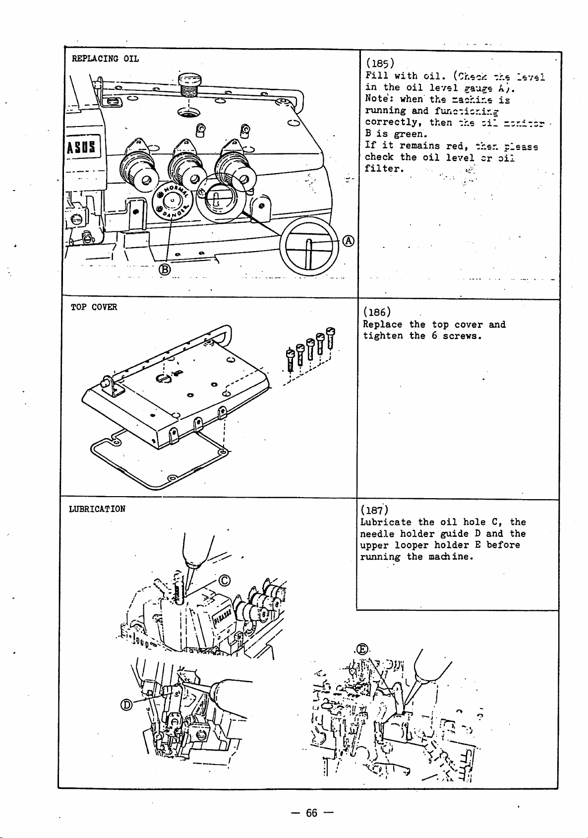
REPLACING
TOP
COVER
OIL
©
(185)
Fill
in
the
Note:
running
correctly,
B
is
If
it
check
filter.
(186)
Replace
tighten
with
oil
when
and
green.
remains
the
the
the
oil,
(Check
level
the
nachir-e
functioning
then
red,
oil
level
top
cover
6
screws.
zhe
^au^e A},
the
oil
then
cr
».•'
and
level
is
nonitor
clease
oil
LUBRICATION
©
:
(187)
Lubricate
needle
upper
running
holder
looper
the
the
holder
machine.
oil
guide
hole
D
E
C,
and
before
the
the
-#1
tl
P) '
M.\W
il
-
66
—
W'
''C'
Page 69

vt''
I
(138)
1-needle
In
the
non-stretch
stitch
2.8mm,
through
- E52 -
2-thread'
case
length
pass
hole
of
threads
is
the
A
stretch
longer
needle
as
when
shown.
threads
the
than
thread
or
(169)
1-needle
(190)
2-needle
- E52 -
3-thread
- E52 -
4-thread
512
67
-
514
Page 70

(I9l)
1-needle
- E56
2-thread
ccrt^=]-':
^1.
1^1
(192)
1-needle
(plain
1-needle
(193)
" E56 -
seaming)
- E56 -
(blindstitch
3-:thread
3-thread
hemming)
-
68
-
505
Page 71

(194)
2-needle
- E56 -
4-thread
IJ^
I
(195)
In
the
non-stretch
stitch
2.8buD,
through
- E52 -
case
length
pass
hole
of
threads
is
the
A
as
stretch
longer
needle
when
shown.
threads
the
than
thread
or
-
69
Page 72

(196) - E32 -
(197)
Double
- S32 -
chainstitch
thread
-
70
-
Page 73

ADJ
UbTHiiiivrc^
NEEDLE THREAD CONTROL
20mm
(lower looper
in
iff
extreme
©
left
[Si
position)
198. (E52)
Needle
Setting
depending
Stitch
Set
'+'
Note:
for
when
guides
If
position,
vary
Stitch
Set
position,
Note:
direction
thread
for
Needle
Set
slot.
Thread
Types
guides
direction.
if
both
sewing
in
they
are
depending
Types
guides
move
,
a
looser
Thread
guide
of
these
on
in
polyester
needle
thin
their
set
stitch
in
guides
for
and
in
Guides
stitch
504t
their
and
fabric,
highest
in
on
503,
their
direction.
a
tighter
in
the
needle
Guide
the
center
2,
guides
type.
512,
lowest
thread
looper
their
formation
machine
505:
highest
2,3in
thread
Right
3
vary
514:
position,
is
threads
then
position.
lowest
will
speed.
the
needle
direction
in
4
of
screw
used
set
position
*+'
seam.
LOOPER
THREAD CONTROL
(lower looper
199.
(E52)
(D
Upper
Setting
depending
Stitch
Looper
Types
(serging,
of
Thread
this
on
stitch
504,
stitch
guide
505,
length
Guide
varies
type
514
more
8
and
and
thread.
503
than .
2.8mm):
Set
gviide
Stitch
hemming)
length
Set
guide
Note:
such
A
for
Lower
Note:
type) and seam
in
it
the
all
stitch
to
B.
Types 512, 503
and 503
less
than
to
C.
when
using
as
wooly
all
stitch
Looper
when
then
'+'
Thread
using
set
direction
types.
(serging,
2.8mm):
stretch
threads,
types.
wooly
requires
takeup
than
(blindstich
threads
set
Takeup
threads
more
2mm
standard
stitch
guide
7
more
to
(G-
thread
in
for
•
in
extreme
right
position)
Lower
Setting
Stitch
Set
Stitch
Set
Note:
such
Move
Looper
depending
guide
guide
when
as
D
for
all
takeup7and
the
'+'
in
seam
for
less.
of
Type
Type
wooly
stitch
direction
emd
this
on
to
to
using
Thread
stitch
504,
E.
503:
D.
threads,
in
Guide
guide
type
505,
stretch
types.S.
guides8and9in
for
the
varies
512,
set
more
direction
9
and
514:
threads
guide
thread
..
thread.
to
-71
-
Page 74

NEEDLE
Stitch
504.
512.514
503
505
503
THREAD
Type
1
Threads
3
4
2
3
2
CONTROL
/////^/
(j^f
p
/•
-//
Application
Seaming
Blindstitch
Hemming
Serging
W
minimum•maximum
3.8(nfli
and
4.3(nin
and
3.8nini
and
4.3(nin
and
Stitch
less(7S
more(6S
less(7S
more(6S
Length
P 1
P 1
P 1
P 1
and
and
and
and
more)
less)
more)
less)
200. (E56)
Needle
1.
•2.
Table
Position
Takeup
(D
®
(D
®
Refer
thread
The
thread
lovest
8
of
1
Thread
standard
Takeup,
to
Table
8
takeup1correctly.
setting
guide
position.
2
is
Needle
Guide
and
in
set
for
its
Thread.
(Fig.
needle
needle
l)
LOOPER
THREAD
Fig.
Fig.
CONTROL
2
3
201.
Looper
1.
Set
guide
screw
2.
Set
the
Set
slot.
3«
Set
slot.
4.
Settings
slightly
threads,
0 Move
direction
the
in
(E56)
Thread
upper
thread
two
thread
thread
thread
the
5
level
9«
lines.
direction
seam.
Takeup,
surface
with
guide
guide7at
guide8in
of
thread
depending
stitch
guides
for
more
•
Thread
(Figs.
of
thread
center
6 midway
guides
on
type
etc.
in
thread
for
Guide
2, 3)
of
between
top
of
middle
vary
operation,
the
'+*
and
less
thread
of
in
(D®^
-
72
-
Page 75

NEEDLE THREAD CONTROL
20mm
(.
I «
( O
202.
(E32)
Needle
Thread
Settings
slightly
Stitch
Set
Type
then
However,
machines
position.
Note
1:
used
for
threads
set
both
3
in
their
direction).
'+'
direction
formation
Note
2:
'+'
direction
thread
a
Needle
Set
and
10
highest
looser
are
and
Thread
thread
the
level
of
these
depending
516:
in
the
in
the
set
them
if
polyester
both
to
sew
needle
highest
If
will
move
guides
in
needle
guide
eyelet
when
position.
Guides
center
case
needle
thin
thread
they
then
be
for
the
thread
Gviide
so
of
2,
guides
on
stitch
of
of
in
their
threads
and
fabric,
guides
positions.
are
set
stitch
uneven.
2
and3in
a
tighter
direction
in
4
that
thread
needle
3
vairy
type.
slot.
E32-450,451
highest
are
looper
then
2
and
('-'
in
the
the
needle
for
seam.
its
eyelet
retainer
is
in
its
(lower
LOOPER
lodper
THREAD CONTROL
(lower looper in
in
y._.
extreme
extreme
left
right
position)
position)
203. (E32)
Lower
In
set
Note:
type)
then
direction
Upper
Setting
and
Stitch
than
Set
Stitch
than
Set
Note
machines
of
Note
such
A
Lower
Setting
and
Stitch
Set
Stitch
Set
Note
on
to
Note
such
D
type.
Looper
the
case
'b'
when
and seam
set
Looper
stitch
Type 515
2.8mffl):
guide
Type 515
2.8mm) and 516:
guide
1:
stitch
2:
as
regardless
Looper
stitch
Type
guide
Type
guide
1:
E32-450,451
F.
2:
as
regardless
Thread
of
E32-450,451
to
4 - 5mm.
using
wooly
requires
takeup
than
varies"depending
2mm
standard.
Thread
type.
(stitch
to
C.
(stitch
to
B.
in
the
case
set
guide
type.
when
using
wooly
v£u:ies
when
when
wooly
to
to
of
Thread
type.
515:
D.
516:
E.
using
using
of
threads,
stitch
depending
machines,
threads,
machine
Takeup
7
machines
threads
more
thread,
more
in
the
Guide
on
8
thread
length
leat;th
of
£32-450,451
toBregardless
stretch
Guide
stitch
stretch
set
type.
set
set
or
9
on
type
threads
guide
thread
guide
threads
guide
stitch
(G-
*+'
less
more
to
516
to
-
73
-
Page 76

CHAINSTITCH LOOPER THREAD
. ®
V
CONTROL
©e—•tei
\ @
" ® :
204. (E32)
o
Adjustment
of
double
chainstitch
looper thread depends on sewing
conditions
stitch
is
made by
guides
o Move
direction
and
in
length
6.
thread
the
such as type
etc.
moving
guides6in
for
This adjustment
the
more
thread
direction
of
thread
the
for
thread,
'+'
in
seam
less.
STITCH
max.
feed
1:2
1:3
1:1.3
1:
diff.
ratio
4
LENGTH
Imm
0.7(nm
1.Gniin
G.6mm
DIPPPERENTUL
ADJUSTMENT
,
V-
1
peed
2
1.5mm
1mm
2.3mm
0.3mm
ratio
Pulley Setting
3
2mm
1.4mm
3.1mm
2.2mm
4
2.5mm
1.7mm
3.9mm
1.5mm
ADJUSTMENT
5
3mm
2mm
4.7mm
1.8mm
6
3.5mm
2.3mm
5.4mm
2.1mm
7
3.8mm
2.5mm
5.9mm
—
205.
Adjustment
1.
Press
pulley
2.
With the pushbutton
in,
stitch
in
pushbutton2and
until
turn
the
length
Table 4 shows the
between
the
feed
This
depending
feed
length
conditions.
206.
The
ratio
feed
diff.
amount
greater
dog
cramped
the
is
stretched
Set
depending
•
fabric.
differential
movement,
amount
the
amount
dogs.
relationship
ratio
according
between
dog
movement
feed
of
diff.
than
(positive
correct
on
pulley
dog
is
it
pulley
is
scale
of
movement
on
type
etc.
feed
the
amount
and
movement.
feed
the
amount
then
diff.
less
(negative
diff.
tiie
operation
engages.
still
until
obtained.
relationship
setting
of
varies
of
cloth,
Adjust
stitch
to
your
ratio
of
the
When
dog
movement
of
the
fabric
feed).
then
the
diff.
feed
turn
pressed
desired,
main
sewing
is
main
amount
main
fabric
feed;.
ratio
and
and
diff.
the
of
the
is
feed
is
When
Adjustment
1.
Open
cloth
nut
1.
Turn
screw
a
bigger
cramped) and
for
a
smaller
(fabric
Tighten
Table
between
setting
5
Lever
•o
[z. '-Z
•
Q
Setting
0) o
1:1.3
1:2
1:3
1:44
—
1:0.7
1:1
1:1.1
2.
Table
5
1
1:0.7
1:1
1:1.5
1:1.6
2
3
1:0.9
1:1.4
1:2
1:2.3
1:1.1
1:1.7
1:2.5
1:2.8
5
4
1:1.3
1:2
1:3
1:3.3
6
—
—
—
1:4
-
74
3.
o
plate
2
anti-clockwise
diff.
t\irnitclockwise
stretched).
nut
1.
shows.the
diff.
of
feed
lever
and
feed
diff.
relationship
ratio
3.
loosen
ratio
feed
for
(fabric
ratio
and
Page 77

feed
dog
tilt
..(D
207.
The
standard
tilt
is
the
feeds
appear
needle
o
However,
elasiic
should
case
or
ply
should
Adjustment
1.
Remove
cover
2.
Loosen
3.
Turn
their
4.
Tvirn
so
tilt.
o When
is
dog
o When
sure
screw9so
play
such
are
above
plate.
in
materials
tilt
of
materials
shift
tilt
screws
plate
screw
pulley
rearmost
screw
that
this
essential
height,
making
to
in
setting
that
level
the
top
the
backwards,
isaproblem,
forwards.
7
8.
9.
and
10
feed
bars
adjustment
to
this
push
screw
that
the
feed
the
when
case
the
where
and
move
position.
and
re-adjust
adjusment,
there
bars.
of
the
teeth
surface
of
feed
take
feed
tighten
have
is
10
feed
of
they
of
extremely
dogs
and
in
puckering
they
off
dogs
screw
desired
made
feed
and
tighten
is
no
dog
all
first
the
the
to.
9
it
be
aide-
AUXILURY
Fig.
(D
FEED
1
DOC
HEIGHT
^"^3
Fig.
2
^t'lH'A' y
208. (E52, E56)
1.
The
height
dogs
there
2.
The
chaining
chain
chaining-off
needle
a When a
then
feed
main feed
o When
then
main
depends
of
the
on
isachaining
land
guide6which
finger
plate.
chaining
the
dogs
top
should
(See Fig.
of
dogs-
there
they
feed
is
should
dogs
no
(i.e.
auxiliary
whether
land.
is
the
faces
on
land
is
the
auxiliary
be
O.Smm
(Fig.
chaining
be 0.8mm
or
the
2).
present,
1,
'c'=p.8mm).
209. (E32) : x :,L : ..
1.
The
auxiliary
depends on machine
to
Table6and
them
correctly.
model
E
32-420
E
32-430
E
32-
440
E
32-450
E
32-451
feed
|Fig.
Auxiliarg
dog
type.
1 and
Feed
0.3mm
0.5mm
height
Dog
feed
not
thread
the
^
below
'c')
land
below
Refer
set
Tables
Height
•••
\} \ i
-
75
-
Page 78

PRESSER FOOT
(3)
LIFT
0.5-"-
ADJUSTMENT
l.Oinm
•
hlct>
twdard
liftmS.Qu
lift-6.Cm
210.
The
presser
distance
plate
foot.
hi^
This
ing
lever
Adjustment
to
Standard
lift
setting
the
1
1. Turn
to
2.
3*
their
Loosen
Set
the
lift
0.5
—l.Omm.
4. Loosen
5.
Push
until
needle
presser
"
position,
it
touches
and
then
6*
Lift
amount,
it
lightly
presser
screw
from
the
is
distance
can
move.
p^ley
lowest
clamp
clearance
shaft
nut
down
distance
plate
foot
tighten
presser
move
arm4and
9-
foot
lift
the
top
bottom
lift
6.0mm.
is
obtained
vhich
and
move
position.
screw
3
and
presser
Tighten
5 and lower
foot
lift
between
and
bottom
is
correct.
set
stopper
intermediate
nut
foot
stopper
touches
is
of
of
the
is
3*0mffl
foot
2.
between
lever
5*
the
8
the
tighten
the
the
presser
by
feed
screw
stopper
top
of
6
so
lever
correct
so
top
needle
and
adjust
lift
dogs
- - • .-
foot
arm
2.
1
of
In
this
that
that
of
to
6.
7
PRESSER
FOOT
ALIGNMENT
©
211.
1.
2.
3.
4.
Loosen
adjusting
Move
foot
needle
needle
Press
onto
needle
screw
Tighten
adjusting
correct
presser
presser
hole
presser
1.
presser
presser
foot
screw.
foot2until
hole
are
aligned.
foot
plate
screw
foot
and
foot
and
down
and
pressure
needle
firmly
tighten
press\ire
obtain
pressure.
presser
plate
-
76
-
Page 79

needle
-
holder
lot'
r
repucement
E52
E32
212. (E32 E52)
1.
2.
3.
4*
Remove
screw
Loosen
2
Fit
tighten
needle
2
Replace
shown
Tighten
and
new
screws
needle
1.
the
remove
needle
the2screws
drop
2
needle
in
screw
2
needle
needle
point
securely.
diagram.
thread
holder
thread
1.
and
retainer
holder
holder.
and
2.
tighten
retainer
screws
lightly
Check
the
as
SHARPENING
87°
OIL
FILTER
KNIVES
62'
INSPECTION
201127
75'
202295
213.
The
upper
and
only
infrequently.
of
knives
time
then
sharpened.
0 When
o
is
especially
part
cutting
Vhen
special
therefore
re-grinding
marked
re-grinding
knife
is
entrusted
specialist
214.
1.
Remove
cover
2.
Take
it.
If
clean
3.
Replace
position.
knife
needs
becomes
edge,
grinder
is
screws
3.
out
it
or
If
lower
'a*
recommend
kept
agent.
oil
is
replace
filter
is
carbon
sharpening
the
cutting
poor
knife
lower
important
hasasharp
upper
is
necessary.
and
that
either
-
2
and
filter
clogged,
it.
in
its
during
should
knife,
knife
that
sharpening
to
us
take
1
and
then
original
tipped
quality
be
that
a
spare
or
off
inspect
either
this
the
a
to
it
We
a
-
77
-
Page 80

O IS
15
1.
2.
Set
Move
rearmost
Set
diff.
noc
is
down.
o
pulley
crank9so
move
movedupand
feed
feed
to
dogs
position.
dogs
if
lever
*7'.
to
that
I : 3
t :
1.3
CH/INGING
215.
Adjustment
1
Changing
1.
2.
3.
4.
Changing
1.
NB
The
sane
as
The
same
as
1:2
do
6
1:2
DIPFERENTUL
Direction
Loosen
Loosen
to
Return
position
See
nut2about
screw
loft
and turn pin 1 180°.
crank4to
and
section
tighten
3
left (Reflating
Movement)
Loosen
of
pin1and
Hote
Position
nut
direction
max.
feed
1
:1.3
1
:2
1 : 3
1:4
diff.
ratio
and
2,
change
re-tighten
of
1:0.7
1:1
1:1.1
Fig.
PEED
of
move
original
in
table
Feed
tighten
of
Pin
washer
1
33
Pin
6mm.
crank
nut
Dog
screw 3.
1
position
1:0.7
1:1
1:1.5
1:1.6
CAPACITY
1
4
2.
on
the
nut
2.
5.
Lever
2
1:0.9
1:1.4
1-:
1:2.3
3
2
2
3
Setting
4
1:1.1
1:1.7
1:1.5
1:2.8
Positioning
1.
1:2
Set
surface
between
2.
1<1.3
so
that
'2'
o
Table
between
Adjusting
After
adjusting
set
pulley'to
and
check
touch
needle
o See
gauge
catalog
0 A
1:4
available.
5
1:1.3
iz
1:3
1:3.3
Fig.
34
Stoppers6and
and
1:3
stoppers
Aoflever
'1'
machines.
lever
and
'5'.
7 shows
lever
Feed
that
plate.
parts
if
they
feed
ratio
See
Table
7
6
—
—
—
1:4
machines.
6,7so
can
'5',
Set
8
stoppers
move
and
relationship
and
feed
Dog Movement
crank9or
'7*,
lever
feed
dogs
list
in
are
changed.
is
also
your
dealer.
that
can
between
ratio.
to
do
parts
7
move
4,
not
Fig.
'5'
35
1.
2'.
Maintain
described
Set
lever
Set
crank4so
that
when
dogs
are
most
position,
clearance
'main
and
feed
dogsis0.5oun.
position
above.
8
to
feed
in
front-
between
diff.
'1',
1.
2.
0
Maintain
described
Set
lever
Set
crank4so
that
when
dogs
are
most
position,
clearance
main
and
feed
dogsis1.0mm.
Shirring
clearance
position
above.
8to'1'.
feed
in
front-
between
diff.
machines:-
is
0.9nm.
1.
2.
Maintain
described
Set
lever
Set
crank4so
that
when
dogs
are
most
position,
clearance
main
and
feed
dogsisO.^mm.
position
above.
8
to
feed
in
front-
between
diff.
'2'.
Page 81

FOR
OLD
TYPE MACHINES
STANDARD
ADJUSTMENTS
For machines manufactured
before)
E32-430/5
NEEDLE
make
HEIGHT
E52
adjustments according to the measurements given below.
6-233-3X3
(l-needle)
before
Jan
1, 1980 (machine #7605896 and
E SERIES CLASSIFICATION
-gauge
-feed
-feed
-lift
-stitch
-fabric
(3x3nm)
dog
dog
pitch
type
(l.6mm)
(standard)
type (516)
weight (medium)
•machine type (E32)
E52
(2-needle)
•n—1/
arrowed
4, .
1
43c5mm
2
5x5mm
3
6x6mm
digit
(low
indicates
lift)
(standard
(high
lift)
E32
©V
216.
lift
lift)
217.
stmodKrd
lift
hlffh
lift
LOVER LOOPER
E52
(l-needle)
• •
9,^-9.7n
• -
lO.S-ll.Oea
E52
(2-needle)
— —3.0~3.2miji
4Si
•
tuidard
hish
I
lift
• -
9.5-9.7Ba
lift
k •
10.8-11.0
218i
E32
standard
lift
a -
hi^h
lift
,a •
3.4-3.6aa
3.0-3.2Ba
-
79
-
standard
hish
lift
a -
a >
3.4-3.^
3.0-3.2)
lift
Page 82

FOR
OLD
TYPE
MA.
CHINES
UPPER
4.5'^
LOOPER
E52
(l»needle)
4.5^5.0mm
5.0mm
E52 (2-4ieedle)
stitch
5.5-"'
type
6.0mm
stitch
512
type
4.5~5.0mm
stitch
516
type
E32
4.5^5.0mm
stitch
219.
type
515
DOUBLE
CHAINSTITCH
LOOPER
5.5
6.0mm
220.
59.5mm
2.0~2.2mm
-
80
-
Page 83

FOR
OLD
TYTE
MACHINES
221.
1-needIe
-
E52
-
2-thxead
/
L
222.
1-needle
-
E52
5-thread
-
-
81
-
Page 84

FOR OLD TYPE
MCHIDJES
\
•223.
2-needle
-
E52
-
4-thread
224.
-
E32
-
-
82
-
Page 85

FOR
OLD
&
TYPE
MACHINES
225.
-
E32
-
226.-E52
-
-
83
-
Page 86

FOR
OLD
TYPE
MACHINES
NEEDLE
THREAD
(lower looper
CONTROL
20mm
in
extreme
7
left
Fig.
position)
227. (E52)
Needle
1
1.
2.
3.
4.
Thread
Set
needle
its
lowest
Set
needle
when
position
thread
thread
Set
needle
in
its
In
the
and 505
thread
highest
Set
needle
in
the
Move
1
and3in
a
tighter
direction
thread
needle
the
guide
slot
lowest
case
(blindstitch
guides
positions.
center
takeup
in
Takeup,
thread
position.
thread
is
lower
1
in
thread
position.
of
1
thread
of
2
and
the
needle
for
the
seam.
Needle
Guide
guide
takeup
in
its
eyelet
is
level
thread
guide
stitch
and3in
guide
long
thread
'+'
direction
thread
a
Thread
(Pig.
left
2
lowest
of
with
takeup
center
type
hemming),
their
right
slot.
guides
and
looser
l)
so
503
in
needle
1
the
2.
for
in
that
3
set
4
the
LOOPER
THREAD
20—21mm
CONTROL
37—38mm
•"i
n
1.0^1.5mm
Fig.
228.
(E52)
Looper
1.
2
o
o
2.
t
3.
4.
Thread
Settings
takeup
takeup
in
the
then,
leftmost
shown
in
the
504,
looper
set
them
lines.
Setting
A =
stretchy
wooly
B =
plain
hemming
C =
stitch
Setting
D =
stretchy
wooly
E =
plain
hemming
Set
as
shown
touch
5
6
case
with
by
case
505
in
thread
looper
Takeup,
of
upper
and
are
of
upper
position,
the
of
and
its
as
shown
of
thread
threads
seaming
type
of
thread
threads
seaming
guide
so
lower
as
stitch
dotted
stitch
514
lowest
threads
threads
that
holder
Guide
looper
looper
follows:
looper
set
lines.
then,
by
guide
and
512
guide
and
9
at
it
(Pig. 2)
thread
thread
type
in
them
types
with
position,
the
solid
7:
such
blindstitch
8:
such
blindstitch
an
angle
does
not
guide
512
its
as
as
base
as
503»
wool
10
o
Settings
vary
depending
thread
(lower looper
in
extreme
right
position)
-
84
o Move
-
direction
the
in
the
thread
'
of
and
for
direction
seam.
thread
on
operation.
guides
more
guides
stitch
in
thread
for
the
less
7
type,
•+'
and
thread
and
8
in
Page 87

FOR
OLD
TYPE
MACHINES/'
20mm
M
©i/o
Fig
Fig.
229.
(E32)
Needle Thread Takeup, Needle
1.
Guide
Set
1
2.
its
Set
that
needle
lowest
needle
when
position,
and
the
are
level.
3.
Set
needle
in
its
o
In
the
set
needle
in
their
4.
Set
needle
so
that
highest
eyelets
of
needle
are
2
o Hove
level.
needle
thread
'+'
direction
thread
foralooser
seam.
needle
the
thread
lowest
case
highest
when
position,
of
thread
guides
and
.in
thread
position.
thread
eyelet
thread
position.
of
thread
thread
needle
retainer
thread
1,3and4in
foratighter
the
needle
(Figs.
guide
takeup 2 so
is
in
slot
of
guide
stitch
guides
positions.
takeup
is
the
bracket
^ide
takeup2and
thread
left
its
of
guide
takeup
cen'.er
type
1 and 3
right
in
thread
right
direction
Thread
1,
2)
1
lowest
1
2
503
its
5
and
4
the
needle
in
the
in
3
4
(lower looper
The
top
Front Cover
surface
of
Hinge
in
37~38mm
extreme
O
1.0~1.5mm
left
position)
Fig.
a
230. (E32)
Looper Thread Takeup, Guides
1.
Set
3
2.
•:
3.
4.
o
o
and
when
lowest
Settings
A =
stretchy
wooly
B =
plain
Settings
C =
stretchy
wooly
D =
plain
Set
thread
does
guide
shown
Settings
vary
and
operation.
Hove
'+'
direction
thread
direction
upper
lower
upper
position.
not
base
in
slightly
thread
in
looper
looper
looper
of
guide
threads.
seaming
of
guide
threads
seaming
guide
touch
11
the
diagram.
of
thread
guides
the
for
thread
thread
is
8:
threads
9:-
threads
10
upper
and
is
depending
for
more
seam
less.
so
guides
8
and
(Fig.
takeup
takeup
in
its
such
as
such
as
that
looper
inclined
8
on
and9in
in
the
it
holder
as
and
thread
the
3)
6
7
9
(lower looper
in
extreme
right
position)
-
85
—
 Loading...