

Page 1

OPERATION MANUAL
www.beerinnovations.com
1
Evolution
OPERATION MANUAL
WWW.BEERINNOVATIONS.COM/Evolution_operation_manual
Page 2
Page 3

OPERATION MANUAL
www.beerinnovations.com
1
CONTENTS
1. PEGAS Evolution device diagram
2. Function of device
3. Technical data
4. Assembly and installation
5. Typical connection pattern
6. Changeover of the universal bottle holder mechanism
7. Dispensing procedure
8. Device maintenance
9. Troubleshooting
10. Safety measures
11. Additional information
12. Disassembling the ow switch
13. Assembling the ow switch
Pegas Evolution Device diagram for ordering spare parts
2
2
3
3
10
12
13
16
18
19
19
20
22
26
Page 4
PEGAS EVOLUTION
6
14
115131210
3
9
2
7
8
4
1
6
1411
5
131210
3
9
2
7
8
4
1
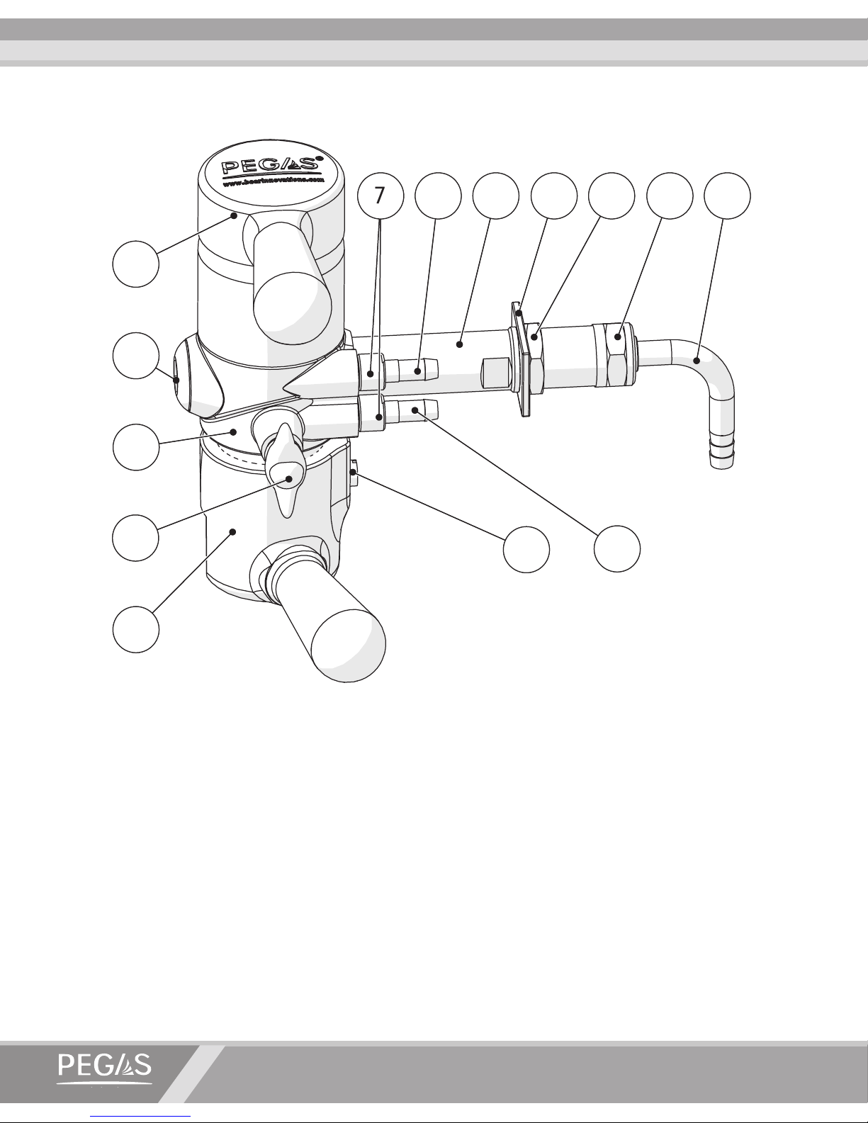
1. PEGAS Evolution Device Diagram
2. Function of Device
The PEGAS Evolution device is intended for fast foam-free dispensing of foamy and/or carbonated beverages (including beer) from pressurized containers (kegs) into plastic bottles with
PCO 1810/1881 or BPF necks.
Dispensing is based on the backpressure method. This method ensures foam-free dispensing which
preserves beverage quality when storing sealed bottles for long periods. The use of new plastic bottles
is recommended for beverage dispensing.
PEGAS Evolution Device Diagram
1. Switch handle 2. Body 3. Plug 4. Throttle valve 5. Universal bottle holder 6. Screw 7. Nut
8. CO2 supply nipple 9. Drain nipple 10. Shank
11. Flat washer 12. 5/8’’ nut 13. Coupling nut 14. Beverage supply nipple
Page 5
OPERATION MANUAL
www.beerinnovations.com
3
4. Assembly and Installation
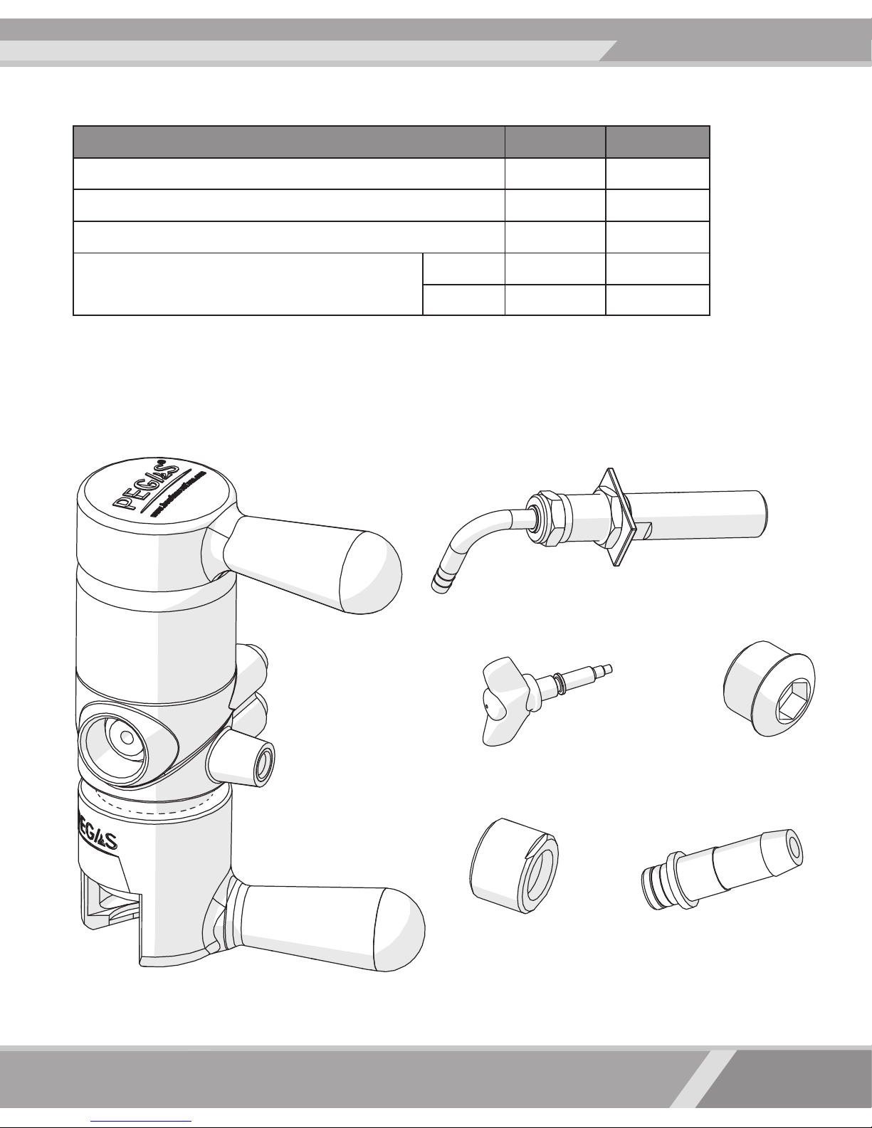
Remove all of the parts from their individual packaging.
* Estimated when lling a two-liter bottle at 60C or less.
** Per liter of product lled under 0.2 MPa of pressure.
3. Technical Data
1. Dispensing device – 1 pce.
2. Shank – 1 pce.
3. Throttle valve – 1 pce.
5. Nuts – 2 pcse. 6. Nipples with rings – 2 pcse.
7. Operation manual – 1 pce.
4. Plug – 1 pce.
Designation Unit Value
Filling capacity* l/hour
45-120
CO2 pressure when supplied to a keg MPa
0,25-0,3
CO2 ow rate (to create backpressure)** g/l
0,25-0,3
Device weight
Net kg
0,75
Gross kg
0,85
Page 6
PEGAS EVOLUTION
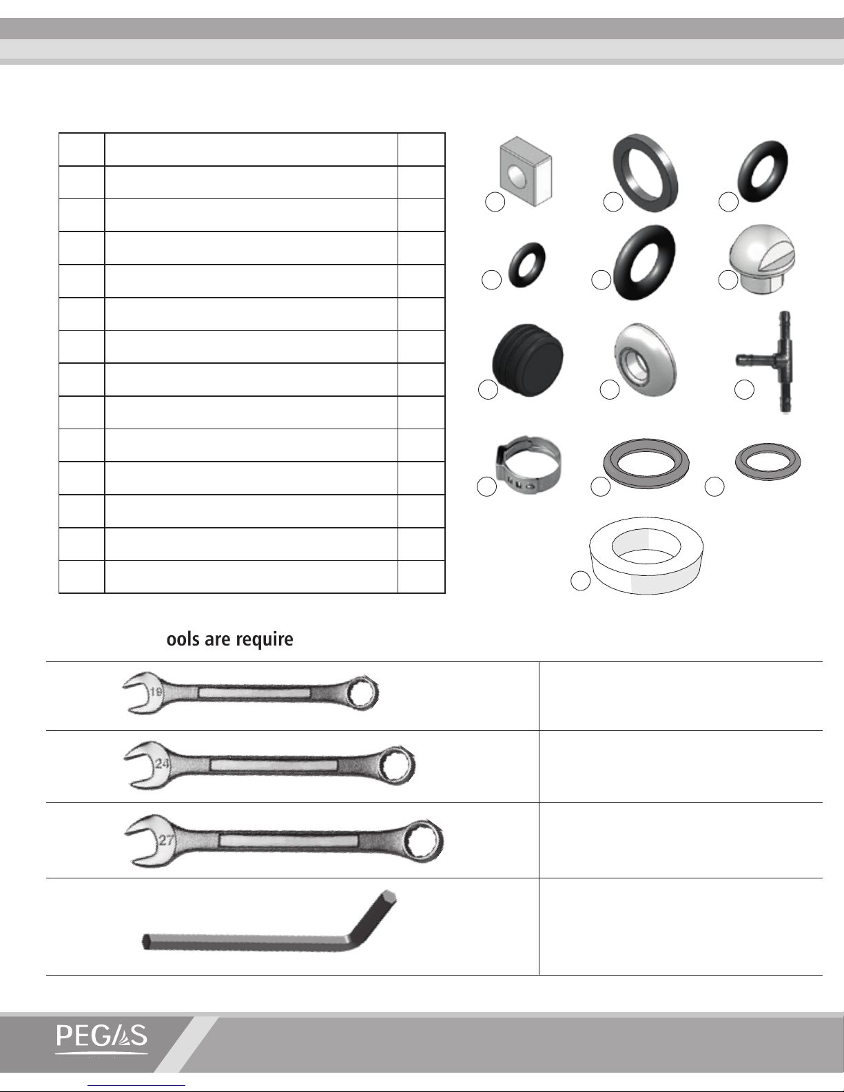
Spare parts set:
Wrench S19
Wrench S24
Wrench S27
Hex wrench S12
The following tools are required for device assembly and installation:
№
IDENTIFICATION
PCS
1 Ram APH.40.00.016 2
2 Gasket PMK.10.00.027 2
3 Ring 008-011-19 APH-5.00.00.804 1
4 Ring 005-009-25-2-6 GOST 9833-73 1
5 Ring 013-017-25-2-6 GOST 9833-73 2
6 Mushroom Knob PG01.02.00.005 2
7 Rubber plug PG01.02.00.003 1
8 Ring PG01.02.02.002 2
9 T-connector PMK.10.00.044 1
10 Clamp d=13,3 6
11
Ring 005-008-19 APH-5.00.00.802
1
12
Ring 003-005-14-2-6 GOST 9833-73
2
13
Gasket PMK.10.00.026
1
1
7
10 11 12
13
8 9
54 6
2 3
Page 7
OPERATION MANUAL
www.beerinnovations.com
5
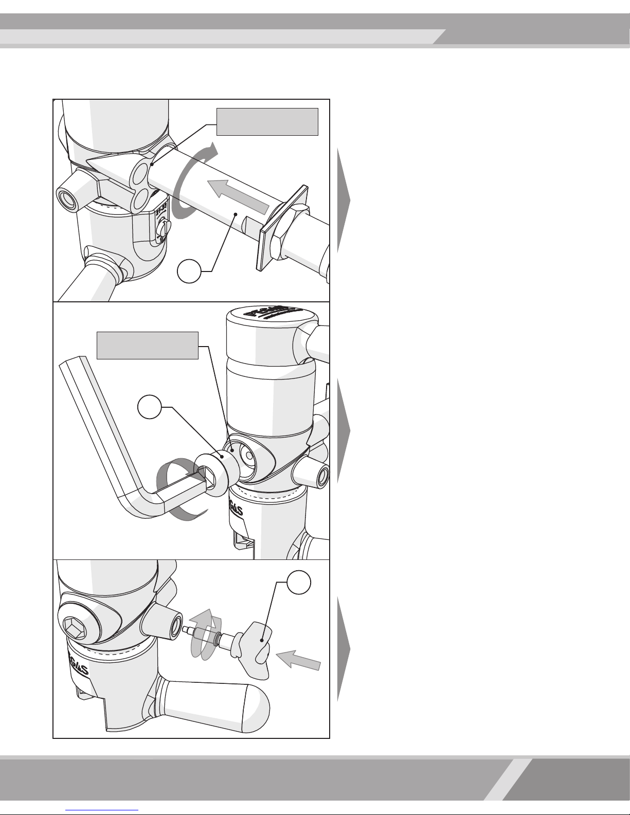
4. PEGAS Evolution device should be assembled as follows:
Before installing the shank, make sure the
device has a gasket.
Using an S19 wrench, screw the shank into
the 5/8” threaded hole in the body.
Using an S12 hex wrench, screw the plug
into the 5/8” threaded hole or for dispensing beer into glasses/mugs. (Tap not included in contents of package)..
Install the throttle valve [4].
10
4
3
Make sure the device
is sealed
Make sure the device
is sealed
Page 8
PEGAS EVOLUTION
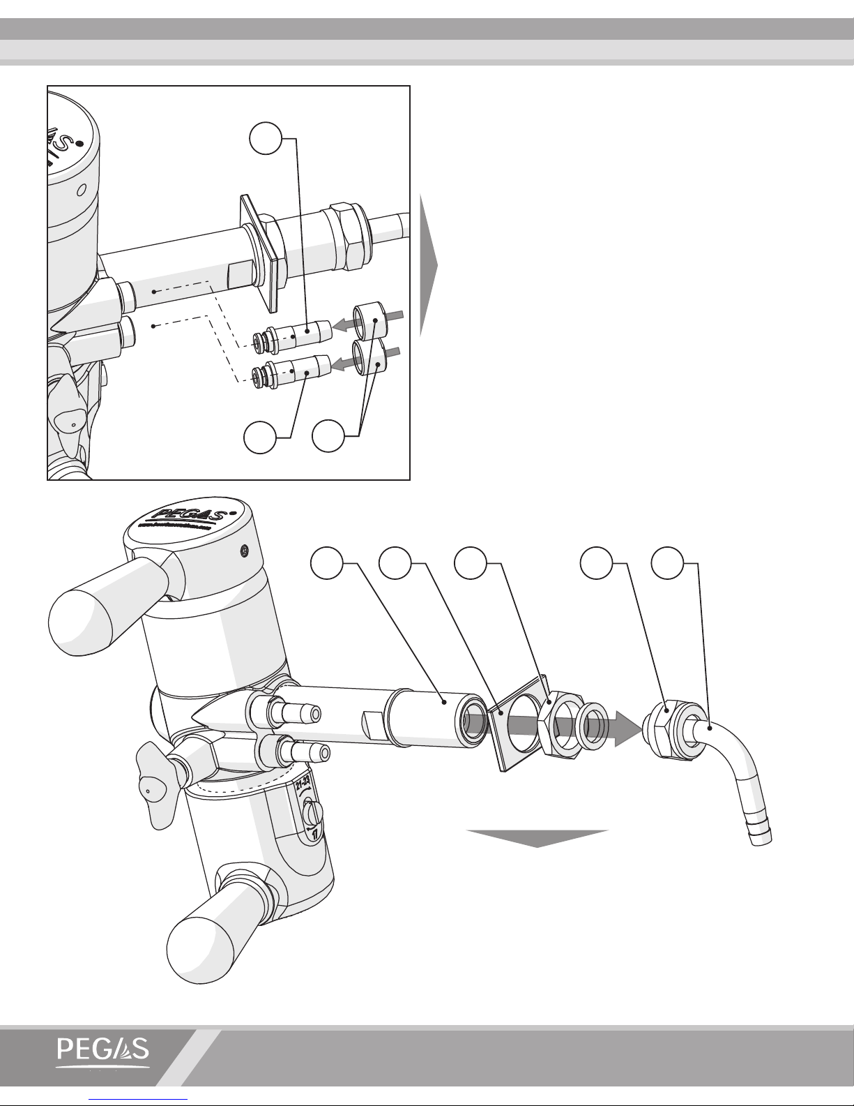
Insert the CO2 supply nipple and the drainage
nipple into the matching holes on the device.
Place the nuts on to the nipples and hand
tighten them up to the stop.
Unscrew the coupling nut [13] from the shank.
Remove the beverage supply nipple [14] together with its gasket. Unscrew the 5/8” nut [12]
and remove the at washer [11]. The device is
now ready for installation.
9
8
1410 11 1312
7
Page 9
OPERATION MANUAL
www.beerinnovations.com
7
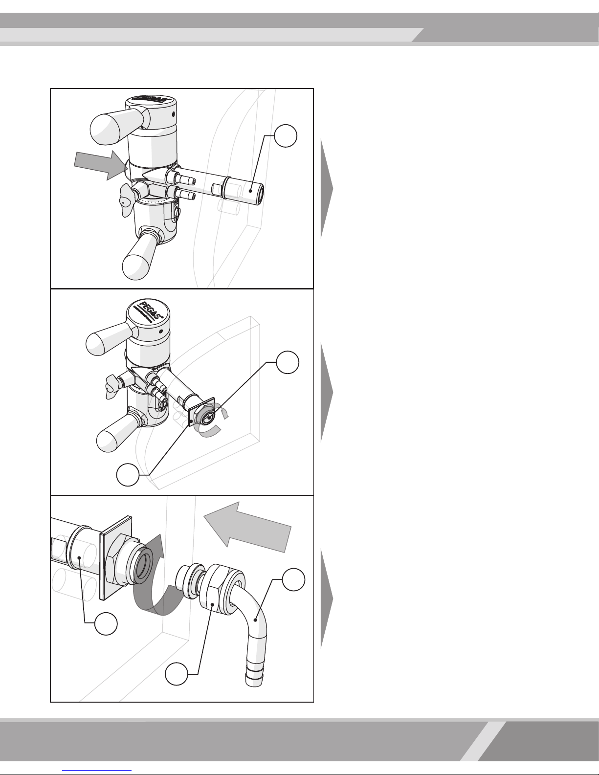
Insert the free end of the shank into the
matching hole.
Place the at washer on to the shank from
the inside; tighten the 5/8” nut using an
S27 wrench, secure the device in a vertical
position with the 5/8” nut.
Place the coupling nut on to the nipple and
tighten it with an S24 wrench. Ensure that
the gasket is properly placed in position.
10
10
12
14
13
11
Installation of the device into a 23+ mm through hole
Page 10
PEGAS EVOLUTION
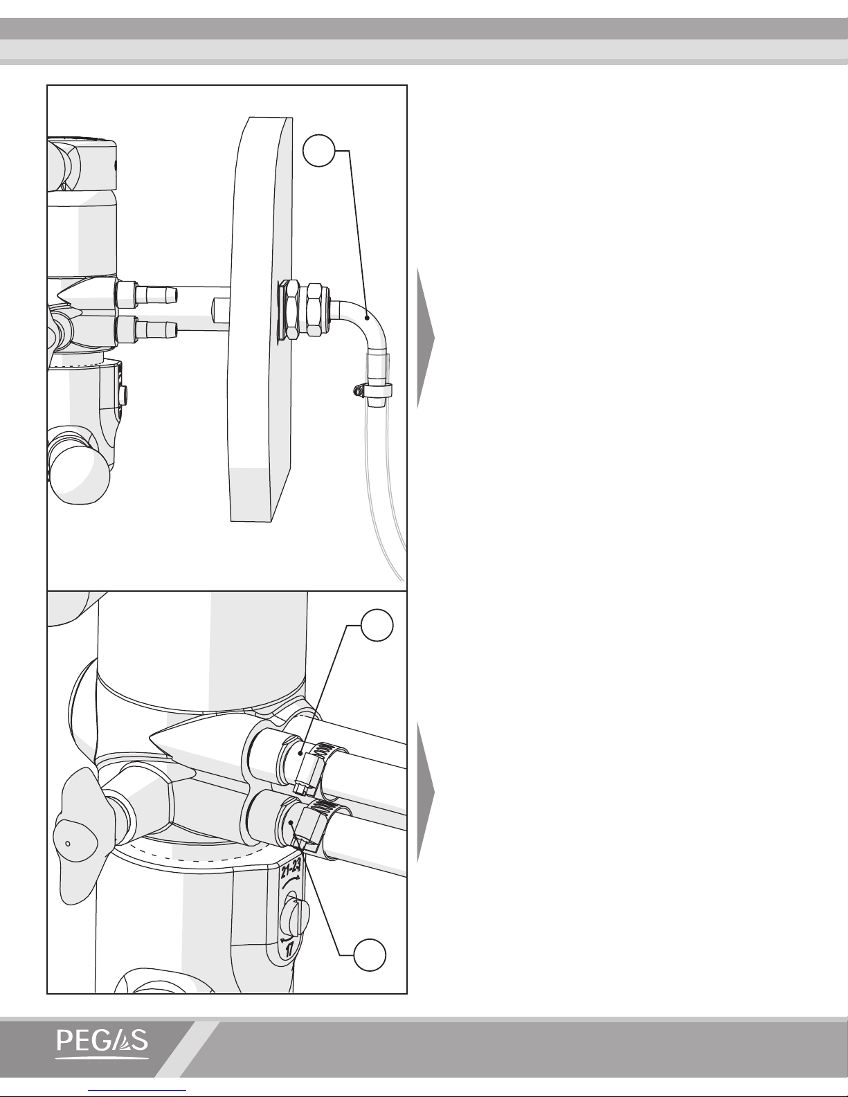
Connect the beverage supply hose to the beverage supply nipple. Fix the hose with a pipe
clip (not included to the package).
Connect the CO
2
supply hose to the upper
nipple. Connect the drainage hose – to the
bottom nipple. Fix the hoses with pipe clips.
14
9
8
Page 11
OPERATION MANUAL
www.beerinnovations.com
9
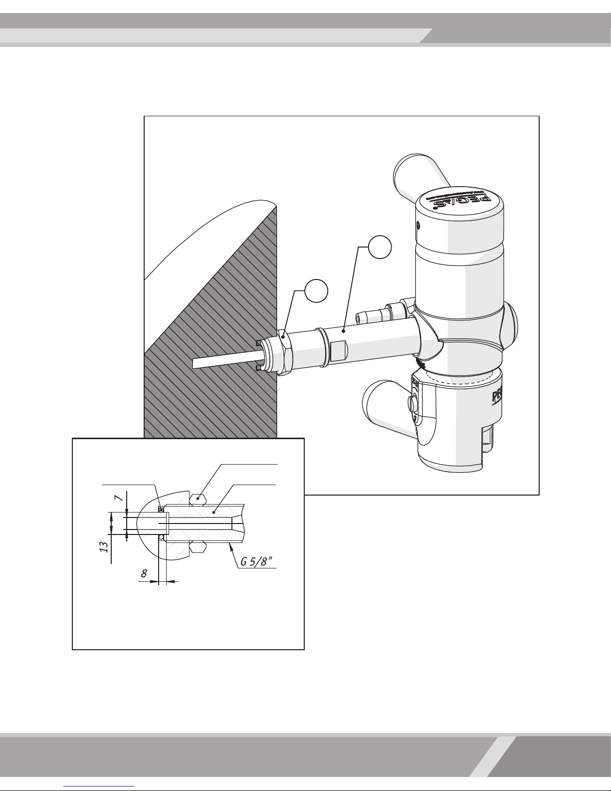
• Place the 5/8’’ nut [12] onto the shank [10]
and tighten.
• Place a gasket into the screw hole with the
dimensions mentioned above.
• Twist the shank into the hole in such a way
that the PEGAS Evolution device is in vertical
position, and the gasket is pressed down to
ensure a proper seal.
• Tighten the nut using a 27mm wrench. The
device is now ready to be used.
When installing device into a G 5/8’’ closed
screw hole, installation should be done according to the following instructions:
Installation of the Device into a Closed G 5/8“ Hole (beer tower)
Installation of the Device
into a screw hole G 5/8’’
Gasket
Nut 5/8”
Shank
12
10
Page 12
PEGAS EVOLUTION
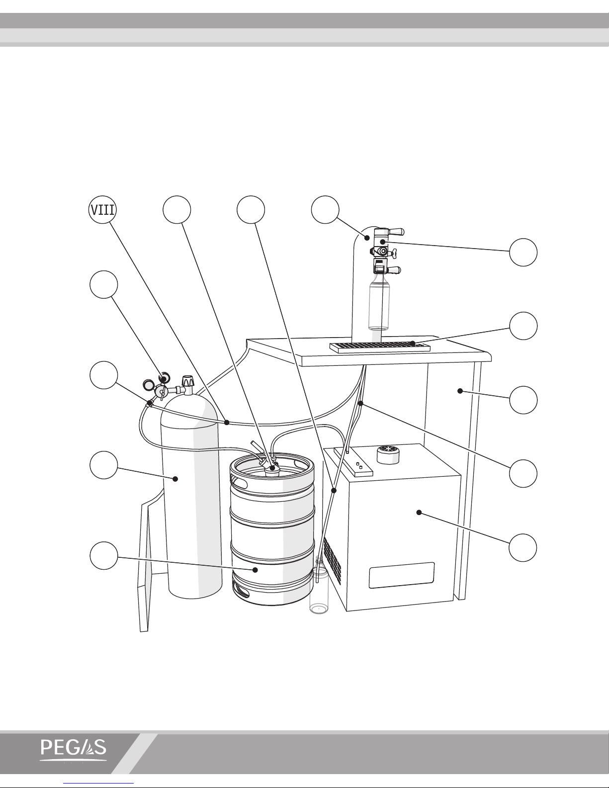
5. Standard Connection
The device should be installed vertically over a table on a hollow-core beer tower with a diameter of
at least 90 mm, or over a bar counter with a through hole with a diameter of 23 mm. The recomendet distance between the axis of the beer supply shank [10] and the table surface should be at least
450 mm. When two or more devices are installed, the recomended distance between axis of their
shank should be at least 150 mm. A drip tray needs to be installed for collecting any spillage.
7
10212
3
9
4
6
5
13
8
11
1
VII
X
II
XII
III
IX
IV
VI
V
XIII
VIII
XI
I
I. PEGAS Evolution Device II. Beer keg III. CO2 gas cylinder with pressure regulator I V. Cooler
V. T-tting VI. Pressure regulator VII. Beer supply hose
VIII. CO2 supply hose IX. Drain hose X. Keg coupler XI. Beer tower
XII. Table top XIII. Drip tray
Page 13

OPERATION MANUAL
www.beerinnovations.com
11
The following equipment is required for device connection:
• Beer keg with a coupler.
• Gas cylinder with pressure regulator (adjustable to 0.15–0.25 MPa).
• Beer cooler.
• Beer supply from the keg and CO2 supply are provided through PVC hoses (with inner diameter
of 7–9mm).
• Pipe clips to secure hoses.
• T-tting.
The device should be connected as follows:
• Supply beer from the keg coupler [X] into the cooler [IV], and from the cooler to the beer supply
nipple [14].
• Supply gas under a pressure of 0,25-0,3 MPa from the gas cylinder [III] through the T-tting [V]
towards the keg coupler [X] and through the hose [VIII] to the CO2 supply nipple.
• Close the free ends of the hoses with pipe clips.
• Connect the hose to the drainage nipple [9]. Put the free end of the hose into the drainage tray.
• Place the hoses [VII-IX] inside the beer tower. To supply the hoses from the device to the beer
tower, drill two holes of at least 14 mm diameter in the beer tower, or install the device onto a
beer tower with ready-made holes.
Page 14
PEGAS EVOLUTION
6. Changeover of the universal holder mechanism
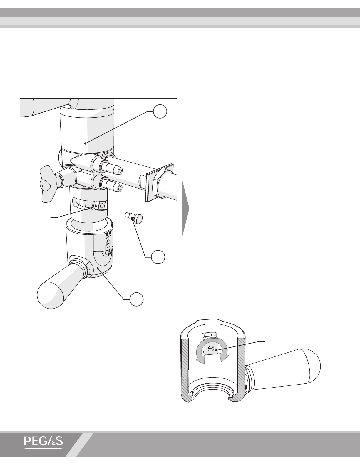
The PEGAS Evolution is equipped with a universal bottle holding mechanism. For beverage dispensing use plastic bottles with PCO 1810, PCO 1881, BPF standard necks.
5
Ram
6
2
Unscrew the device [6] and remove the
bottle holder mechanism from the unit.
The ram will be left in the groove of the
housing. Take out the metal plate, turn it
and set in the desired position. Install the
bottle-xing mechanism back in to the unit
ensureing that the ram is in the groove of
the unit. Align the metal plate hole with
the ram hole and tighten the screw up to
the stop.
Plate
Page 15
OPERATION MANUAL
www.beerinnovations.com
13
7. Dispensing procedure
Before dispensing make sure the device is properly installed and connected, and that all of the
joints are sealed tightly. Dispensing into plastic bottles with the PEGAS Evolution should be done
as follows:
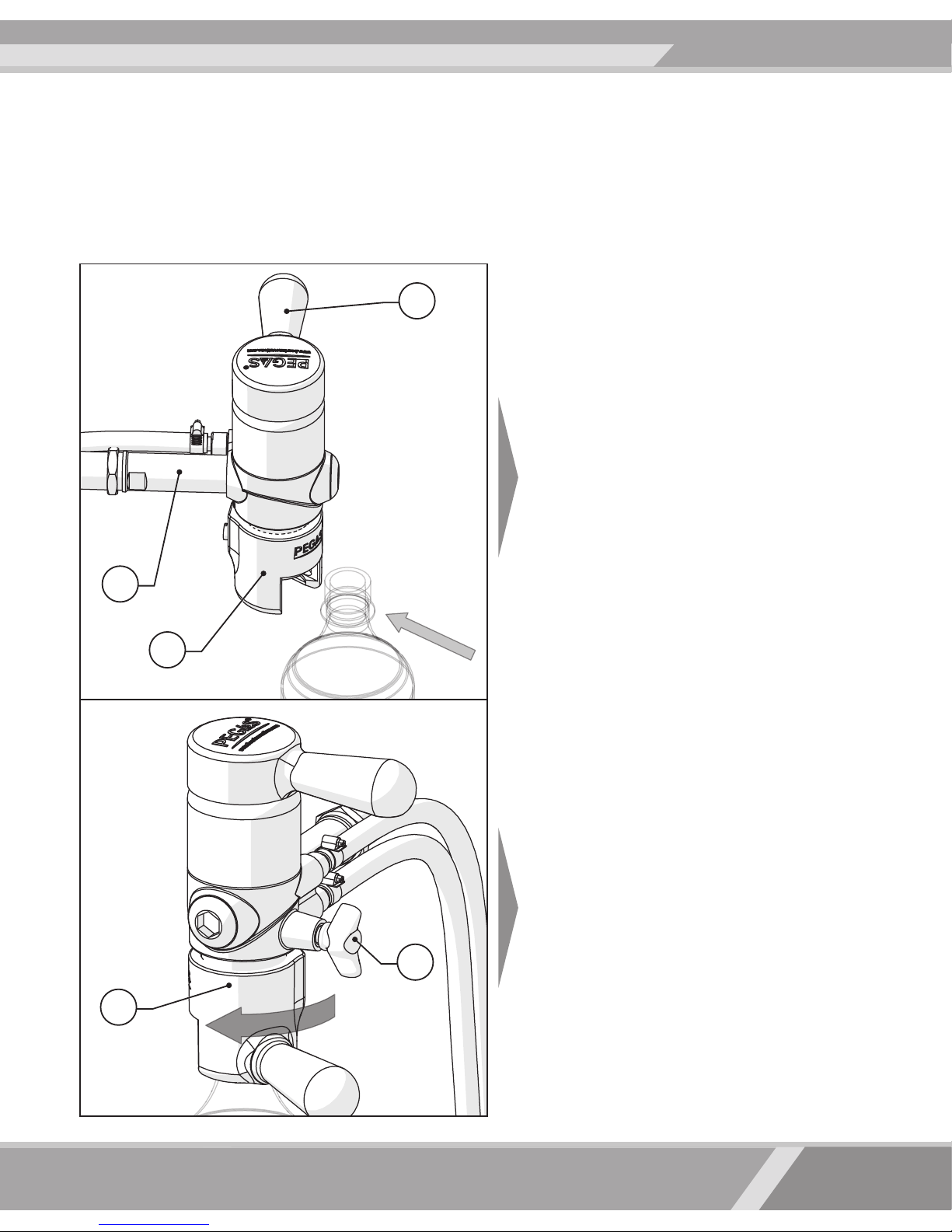
Initial Position
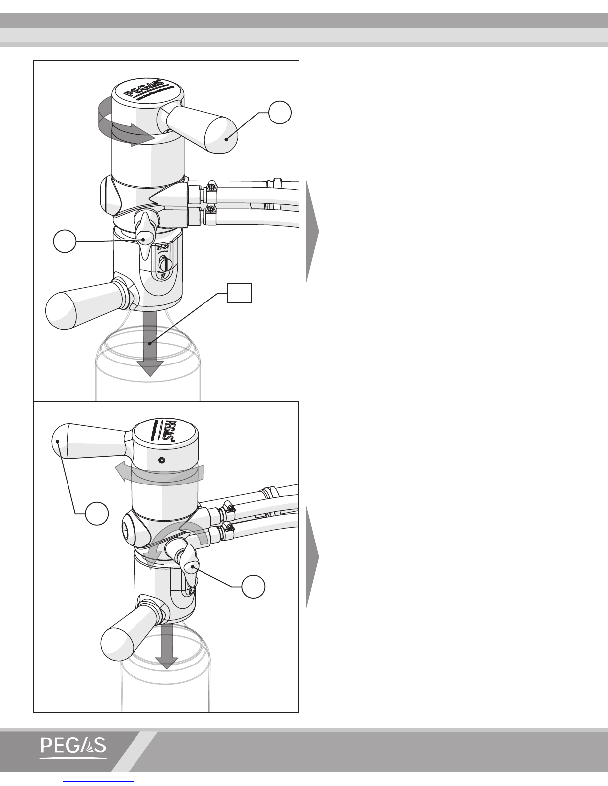
Ensure that the switch handle [1] is in its
neutral position, it should be perpendicular
to the shank all supplies are of. The bottle
holder [5] is turned to the right until it stops.
The throttle valve [4] is closed (turned clockwise until it stops).
Insert a PET bottle into the slot of the bottle
holder.
Securing the bottle in the holder
Turn the bottle-holder to the left ensuring
that the bottle neck is pressed tightly against
the sealing gasket.
1
5
5
10
4
Page 16
PEGAS EVOLUTION
Filling the Bottle with CO
2
until it stops, this will supply CO2 into the
bottle (throttle valve remains closed). The
average time for lling a two-liter bottle is
3-5 seconds. Feel the bottle to make sure
it’s hard.
When switching the channels do not lift
the handle!
Filling the Bottle with Beverage
Pull the switch handle to start beverage
dispensing. Set the throttle valve to a half-
open position. Control the process of lling
the bottle by adjusting the throttle valve. If
the beverage becomes too foamy – slightly
close the throttle valve, if the ow is too
slow – open the throttle valve.
CO
2
4
1
1
4
Page 17
OPERATION MANUAL
www.beerinnovations.com
15
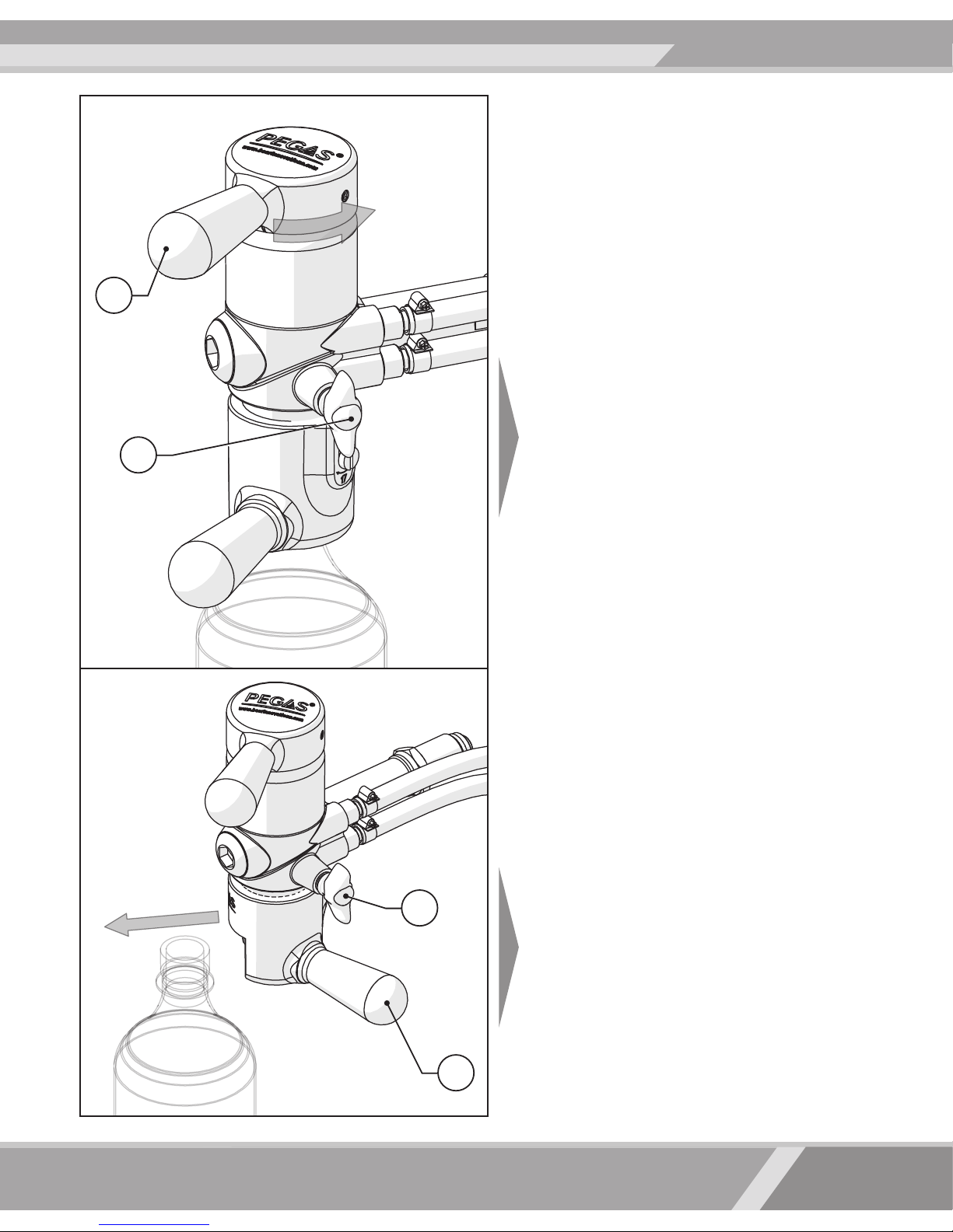
Completion of Dispensing
Once the bottle is lled, return the switch
handle to its neutral position and open the
throttle valve completely.
Bottle removal
Wait a few seconds until the pressure in the
bottle equalizes to the atmospheric pressure. Close the throttle valve. Turn the bot-
tle-holder to the right and remove the lled
bottle from the device.
In order to preserve beer quality, seal the
bottle with a leak-proof cap as quickly as
possible.
4
4
5
1
Page 18
PEGAS EVOLUTION
8. Device Maintenance
Only the personnel who have studied the operations manual and have been trained to safely
operate the device should be allowed to maintain the device.
A heavy daily beer ow through the PEGAS Evolution may eventually clog the beer supply ele-
ments, as well as the drain and throttle parts, and hoses.
In order to avoid the clogging and fouling of device elements, the dispenser should be washed
and disinfected regularly.
Washing
To clean the device a sanitary liquid should be supplied from a hose-adapted container placed
at the beer keg position. The beer supply hose and the PEGAS Evolution device itself are the
rst ones to be washed. In order to wash the drain hose, a plastic bottle should be placed into
the down-hold mechanism. When the plastic bottle overows, the drain and throttle elements
are clean.
PEGAS Evolution Sanitary Standards
Sanitary Rules for the Brewing and Beverage Industry (СП) 3244-85* stipulate that dispensing
devices should be washed daily for 30 minutes both in hot (60°C) and cold water.
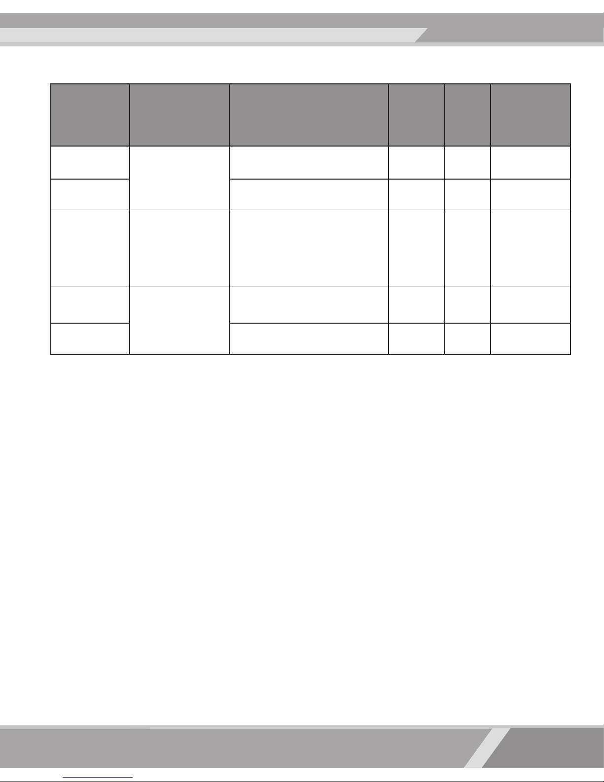
Weekly disinfection of the device (using Antiformin, Sulfochlorantin, Benzalkonium Chloride disinfectants) and a thorough rinse with water until the full dissolution of the disinfecting agent has
been reached is required.
* This standarts is currently in effect in the territory of the Russian Federation. Maintenance of the device should be done according
to the schemes described by Chart 1.
Page 19
OPERATION MANUAL
www.beerinnovations.com
17
Sanitary procedures:
• Disconnect the beer keg from the beer supply system.
• Prepare a container for collecting used used water/cleaning agent.
• Make sure that the changeover valve handle is in its middle position.
• Connect the beer dispensing system to the source of water/cleaning agent.
• Place an empty plastic bottle (preferably of small capacity) into the universal bottle holder; fasten
it by turning the bottle holder lever to the left.
• Open the throttle valve.
• Pull the switch valve handle until it stops.
• Make sure to control the rate of ll as it can overow rapidly. Be prepared to collect any excess
solution from the drain hose.
• Sanitary procedures should be implemented according to time frames prescribed by the chart.
• In order to stop the supply of water/cleaning agent, turn the switch valve handle to its neutral
position.
• Remove the bottle from the device.
• Use a clean cloth to remove the remaining water/cleaning agent from the surface of the PEGAS
Evolution device.
Type of
sanitary
procedure
Frequency Cleaning agent
Time,
min.
t0 , C
Source of
cleaning
agent
Washing
Every day after
use
Water 10 20 Water pipe
Rinsing Water 15 70-85 Water pipe
Disinfection Weekly
Lerades C 178 or similar
agents used in food
processing equipment
disinfection
10-15 60
Container
with a proper
tting
(wash-keg)
Rinsing
After each
disinfection
Water 10 40-60 Water pipe
Rinsing Water 15 20 Water pipe
Sanitary and hygienic measures:
Chart 1
Page 20
PEGAS EVOLUTION
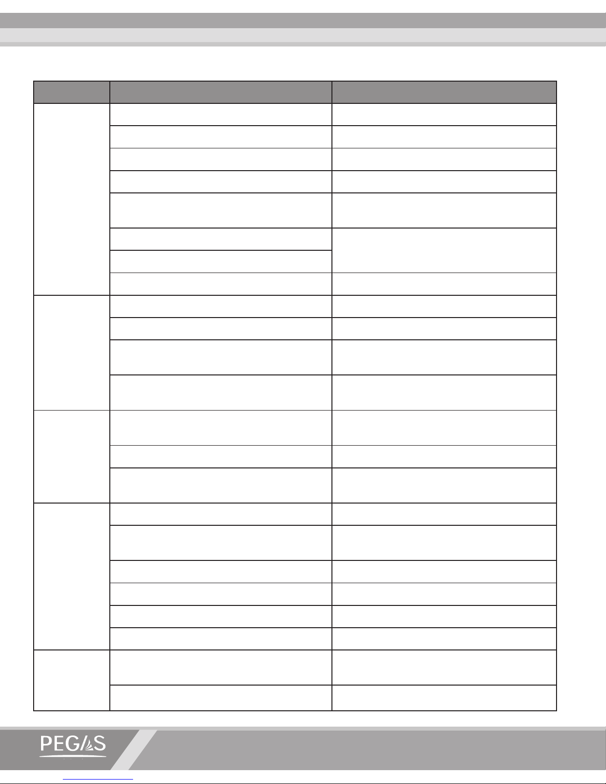
Problem Possible cause Steps to solve the problem
Beer does not
pour
No beer in the keg Replace the keg
Coupler is not connected to the keg Connect the coupler to the keg
No gas in the gas cylinder Replace the gas cylinder
Pressure regulator is closed Open the pressure regulator
Improper connection of hoses to the device
Check that the hoses are connected properly,
reconnect them in the right sequence
Hoses or their joints are damaged
Replace the hoses that are out of order
Beer/gas supply hoses are clogged
Pressure release valve is closed/clogged Open/unclog the pressure release valve
Gas is not
being supplied
into the bottle
No gas in gas cylinder Replace the gas cylinder
Pressure regulator is closed Open the pressure regulator
Improper connection of gas supply hoses to device
Check if hoses are connected properly, reconnect
them in the right sequence
Hoses or their joints are damaged
Replace hoses, make sure that joints are connected
tightly
The bottle
does not t
in the xing
mechanism
properly
Bottleneck does not correspond to standards
stated in the operation manual
Use the correct bottles or try other bottles
Bottle xing mechanism is damaged Check and replace the bottle xing mechanism
The bottle holder is not set correctly
Proceed with a bottle holder mechanism
changeover as described in section 6
A lot of foam
during bottle
lling
Pressure release pace is too fast Adjust the pressure release pace
Pressure regulator is set incorrectly
Set pressure according to the type of beer
dispensed
Gas in the gas cylinder is running out Replace the gas cylinder
Beer in the keg is running out Replace the keg
Not enough gas is supplied to the bottle Supply more gas into the bottle
Beer supply hose is clogged/greased Wash the device
Beer leaks
when the
changeover
valve is closed
Foreign objects are clogging the beer channel
Unclog the beer channel and remove
any foreign objects
Rubber gaskets in the beer channel have worn out Replace the worn-out gaskets
9. Troubleshooting
Page 21

OPERATION MANUAL
www.beerinnovations.com
19
10. Safety Measures
It is important to follow certain operation rules in order to ensure the reliability of the device.
• Containers used for dispensing should correspond to sanitary and hygiene requirements set
forward to foodstuffs packaging. Bottles must be clean and bear no visible signs of damage or
cracking.
• The device requires regular maintenance.
• Do not set the device pressure to a position higher than 0.4 MPa.
Regular washing and disinfection as well as a constant monitoring of the sanitary condition of the
PEGAS Evolution will ensure a long life span and smooth function of the device.
11. Additional Information
No part of this operations manual shall be copied, transferred, re-written, saved as a reserve copy
or translated into any language in any form and by any means without prior written notice issued
by Novosibirskprodmash Production Association, Ltd.
Novosibirskprodmash Production Association, Ltd. reserves the right to change characteristics
and properties of the device described in the present manual at any time and without prior no-
tication.
Novosibirskprodmash Production Association, Ltd. bears no responsibility for any damage connected to the use of the PEGAS Evolution device. Novosibirskprodmash Production Association,
Ltd. would appreciate any information in relation to errors and aws found in the this operations
manual.
Page 22
PEGAS EVOLUTION
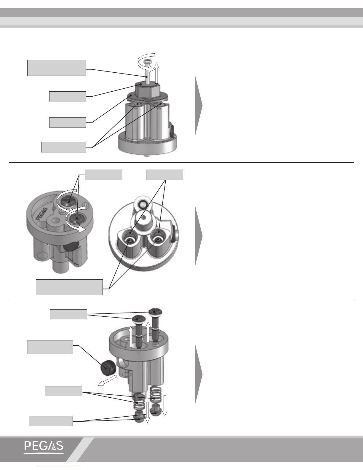
12. Disassembling the ow switch:
1.1 Unscrew the self-drilling screw 3,5x25
and remove the cam with a washer installed on it.
1.2 Holding the mushroom knob with a
6mm wrench, unscrew the valves each after
each using a slot head screw driver.
1.3 Take out the valves, the springs and the
rubber plug.
Self-drilling screw
3,5x25
Valves
Valves with unscrewed
mushroom knobs
Mushroom knobs
Cam
Washer
Springs
Valves
Rubber plug
Springs
Mushroom knobs
Page 23
OPERATION MANUAL
www.beerinnovations.com
21
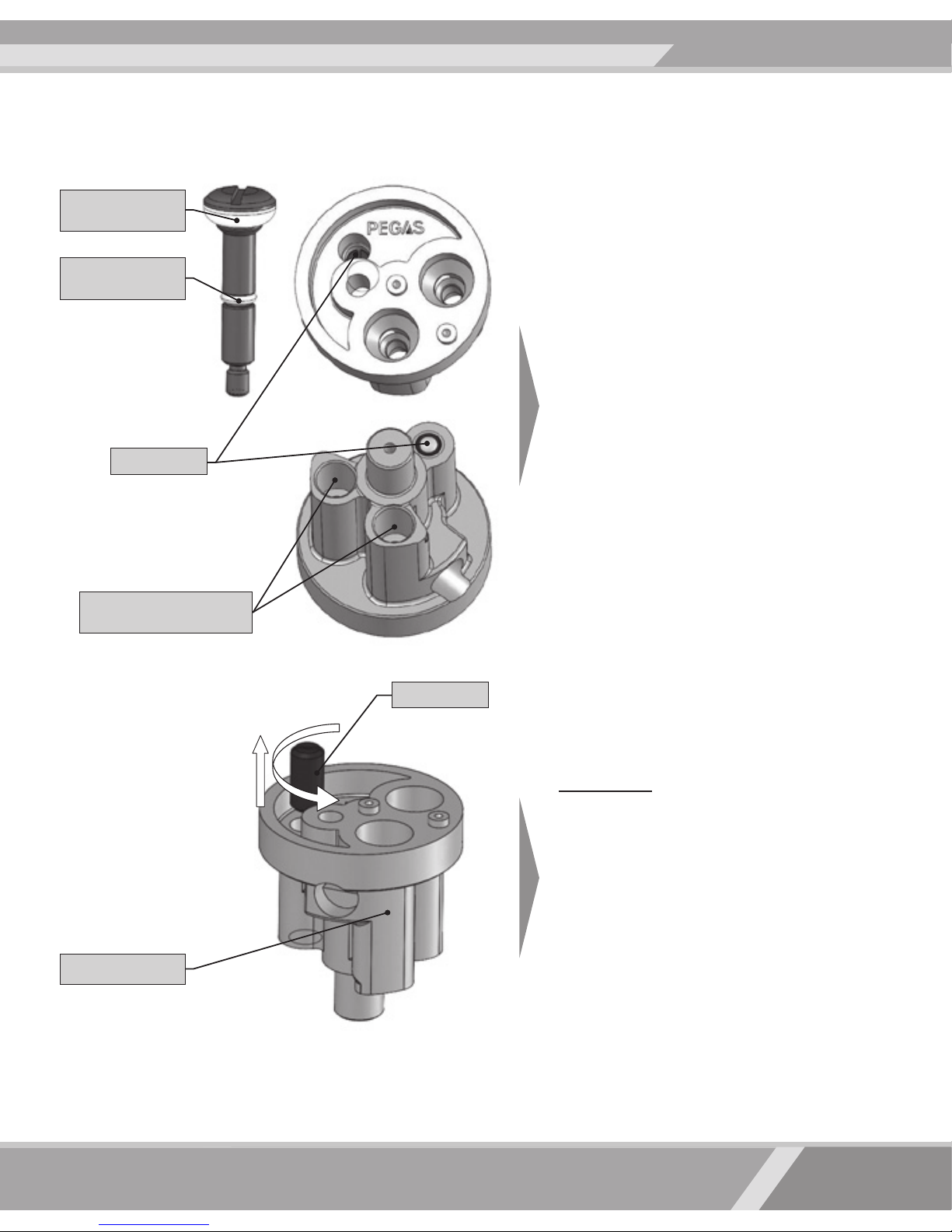
1.4 If necessary, remove with dry soft tissue old lubricant and trace impurities from
the outer surfaces of valves, springs, mushroom knobs and cam as well as from the
interiors of the switch unit. Replace rubber
seals (ring PG01.02.02.002 and ring 003005-14) on the valve, in case they have any
conspicuous mechanical damages.
If necessary, use the following washing
solutions:
Lerades C 178, Neomoscan sepa or Termit
Galo.
Use of other cleaners may cause damage
to the rubber rings, loss of tightness of
the connections and interruption of the
warranty maintenance.
Attention! If it is necessary to fully soak
switch in the washing liquid, unscrew
the lock with a slot head screwdriver or
prevent washing solutions getting on
the ball of the lock to avoid any breakdowns.
Ring
PG01.02.02.002
Ring
003-005-14
Cavities that should be
cleaned from the lubricant
Lock
Switch unit
Lock
Page 24
PEGAS EVOLUTION
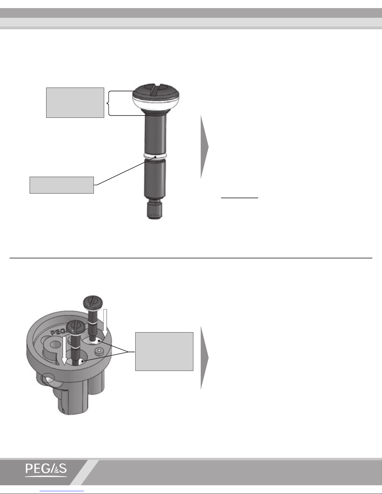
13. Assembling the ow switch:
2.1 Lubricate the ring 003-005-14 with a
thin layer of the Berulub Sihaf 2 or Berulub PV Dab 10 lubes. Using, for example,
a sponge or a piece of cloth with some lubricant on it.
Use of other lubricants may cause dam-
age to the rubber rings, loss of tightness
of the connections and interruption of
the warranty maintenance.
Attention! Prevent any lubricant getting
onto the ring PG01.02.02.002 and bearing surface areas.
2.2 Install lubricated valves into the switch
unit. Being inside the body, the valves
should move smoothly and without any
sticking.
Attention! If the valve is not lubricat-
ed, the ring 003-005-14 may be cut off.
Make sure that there is no lubricant on
the switch conic bearing surface areas
touching with the ring PG01.02.02.002.
Prevent lubricant
contact with
this area
Make sure there
is no lubricant
on the bearing
surface areas
Lubricate the ring
003-005-14
Page 25
OPERATION MANUAL
www.beerinnovations.com
23
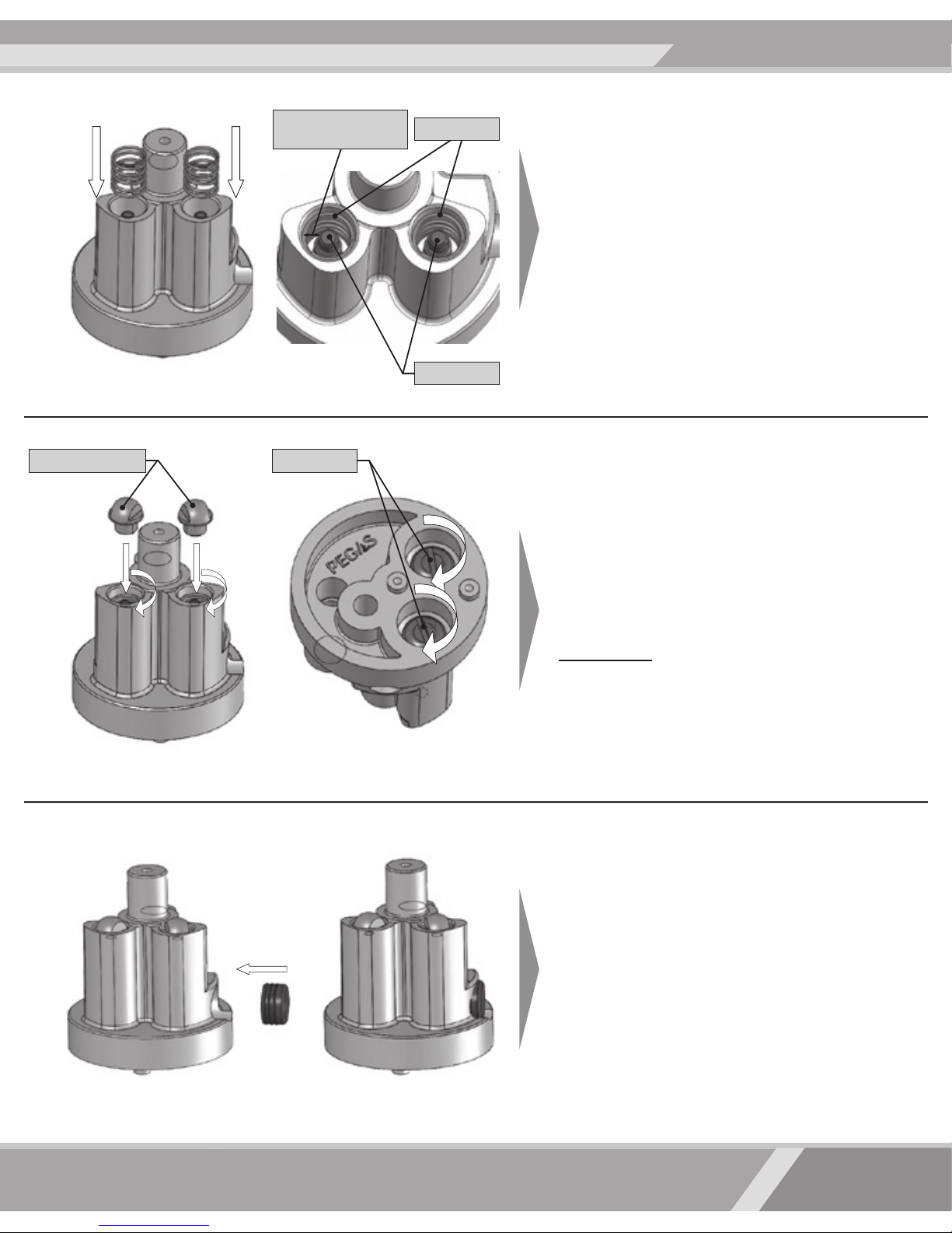
2.3 Install the springs into the switch unit
holes and apply a 0,55 ml coat of lubricant
(see Item 2.1 for the lubricant brands) on
the hole bottom under the spring between
the valve shank and the body wall on one
cavity, which is equal to 1/3 of its volume.
2.4 Manually screw the mushroom knobs
on the valves on 1-2 turns. Then, holding
the mushroom knobs with a 6 mm hook
wrench, rmly screw the valves with a slot
head screwdriver.
Attention! If the mushroom knob is
screwed with a moment more than
0,15 Nm, its thread may be overturned.
2.5 Firmly install the rubber plug into the
switch unit hole so that all the plug’s lamellae are inside of the switch unit.
Springs
Valves
ValvesMushroom knobs
Lubricant
application area
Page 26
PEGAS EVOLUTION
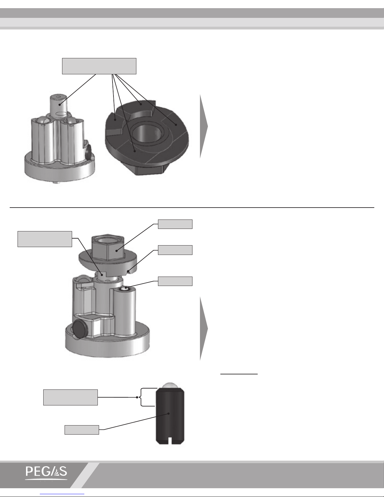
2.6 Apply a thin coat of lubricant on the
switch unit axis and on the cam’s surface,
depicted on the drawing. Use the lubricant
specied in the Item 2.1.
2.7 Install the cam on the switch unit axis
aligning cam cut with the ball of the spring
lock (if the lock was unscrewed).
In case the lock was unscrewed, install the
cam, apply Loctite 270 on the lock shank
and then screw it with a slot head Screwdriver until the ball of the lock touches
cam’s cut.
Attention! Prevent thread locking Loctite
270 getting onto the ball of the spring
lock.
Lock
Lock
Cam
Cam cut
Loctite 270
application area
Switch unit axis
Lubricant application
areas
Page 27
OPERATION MANUAL
www.beerinnovations.com
25
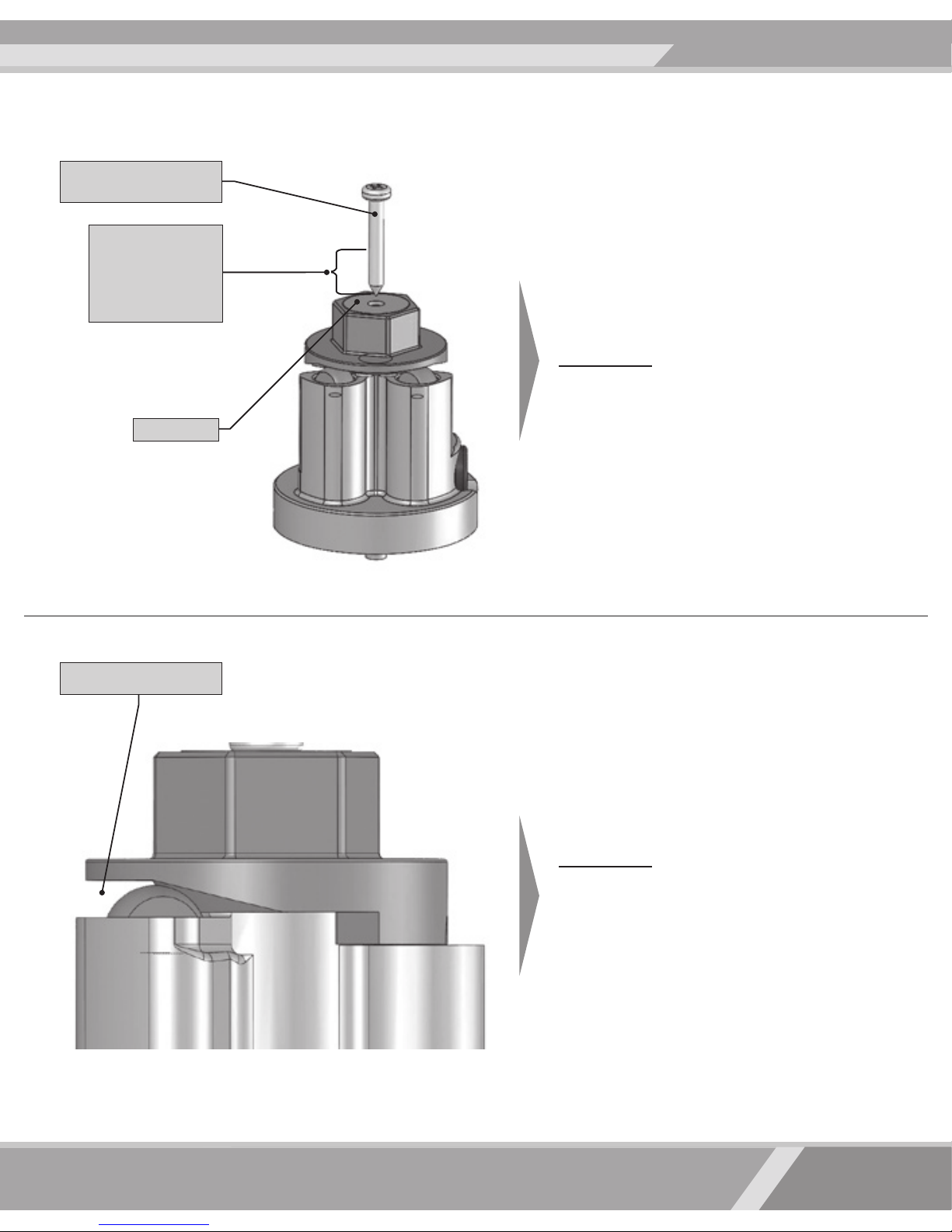
2.8 Install the washer on the cam and rmly
screw self-drilling screw 3,5x25 with a force
not bigger than 1Nm.
Attention! To prevent self-unscrewing,
apply thread locking, for example Loctite 270, on one third of the self-drilling
screw thread area. It is allowed to use
glue “Moment”.
(but not “Moment Contact”!!!)
2.9 Check to see that there is a 0,5 mm gap
between the cam and the mushroom knobs.
Attention! If there is no gap, it may be
that the valves are not screwed tightly
or the mushroom knobs’ thread is overturned. In the rst case, as in the Item
2.4, the valves should be screwed up. In
the second case, replace the mushroom
knobs.
Self-drilling screw
3,5x25
Check to see the gap
Application area
of the thread
locking (Loctite 270
recommended)
Washer
Page 28
PEGAS EVOLUTION
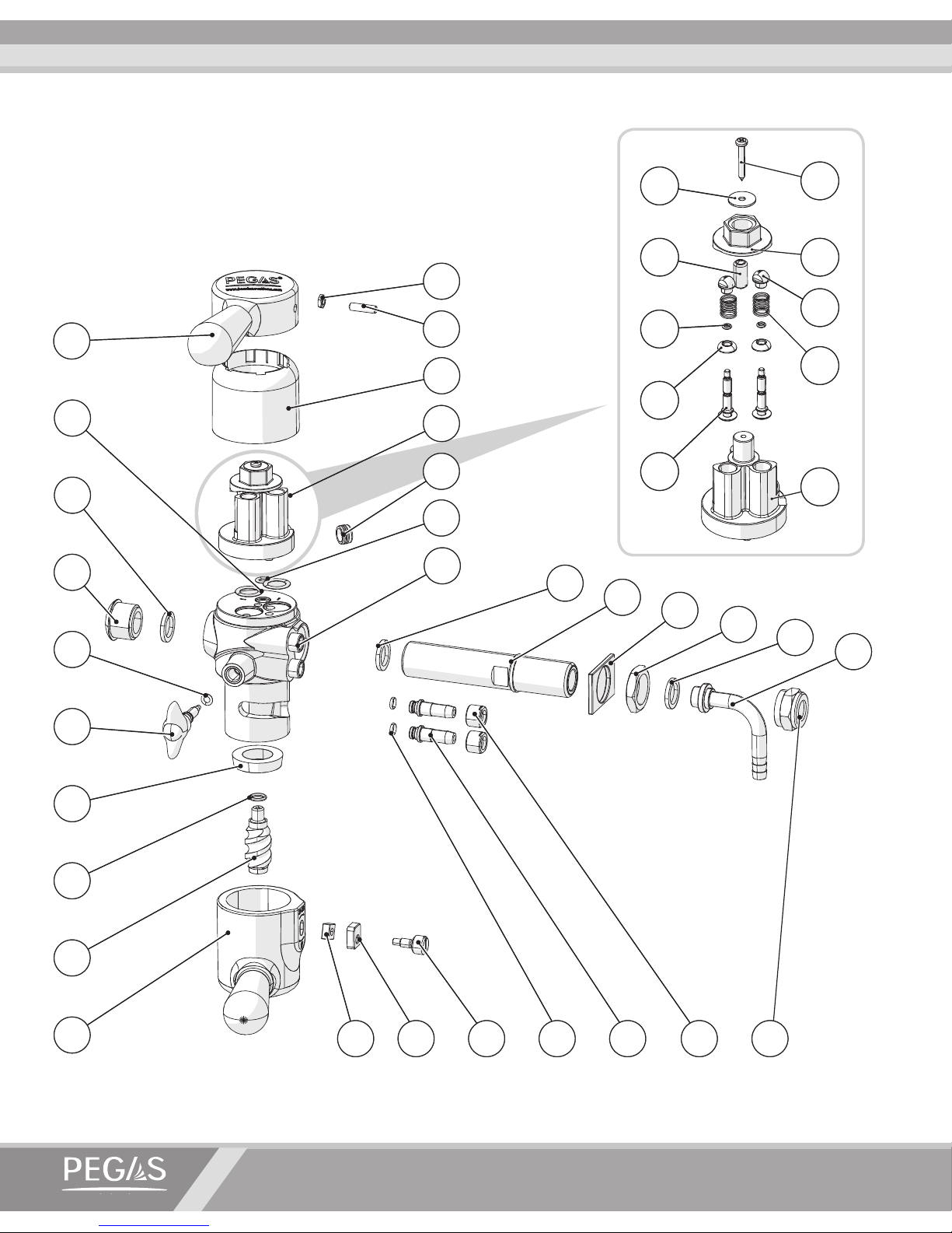
Device diagram for ordering spare parts
5
34
3231
30
38
33
25
27
19
26
17
18
16
19
35 36 37
20
4
21
28
22
2
19
23
3
24
29
1
5
34
3231
30
38
33
25
27
19
26
17
18
16
19
35 36 37
20
4
21
28
22
2
19
23
3
24
29
1
15
14
9
13
12
11
10
8
7
15
14
9
13
12
11
10
8
7
6
Page 29
www.beerinnovations.com
№
DESCRIPTION IDENTIFICATION
1
Lid PG 01.00.00.001
2
Nut DIN 439
3
Setting screw DIN 914
4
Sleeve PG 01.00.00.002
5
Switch PG 01.02.00.000
6
Self-drilling screw DIN 7981
7
Washer DIN 9021-5
8
Cam PG 01.02.00.002
9
Ball lock K0309.208
10
Mushroom Knob PG 01.02.00.005
11
Spring PG 01.02.00.001
12
Ring 03-005-14 GOST 9833-73
13
Ring PG 01.02.02.002
14
Valve PG 01.02.02.001
15
Switch unit PG 01.02.01.000
16
Rubber plug PG 01.02.00.003
17
Ring 005-009-25 GOST 9833-73
18
Ring 013-017-25 GOST 9833-73
19
Gasket PMK 10.00.027
№
DESCRIPTION IDENTIFICATION
20
Shank APH 40.03.000
21
Flat Washer PMK 20.01.001
22
5/8 Nut PMK 10.00.054
23
Nipple 00.03.001-01
24
5/8 Coupling Nut 00.03.002-01
25
Plug APH 40.00.008-01
26
Body PG 01.01.00.000
27
Gasket PMK 10.00.026
28
Ring 005-008-19 APH 5.00.00.802
29
Throttle Screw APH 15.03.00.000
30
Screw APH 40.00.004
31
Ram APH 40.00.016
32
Plate PMK 20.05.001
33
Roller screw PG 01.00.00.004
34
Bottle holder PMK 20.05.002
35
Ring 006-008-14 GOST 9833-73
36
Nipple PG 01.04.00.001
37
Nut PG 01.00.00.003
38
Ring 008-011-19 APH 5.00.00.804
Page 30
www.beerinnоvations.com
 Loading...