

PeerlessBoilers WBV-03-060, WV-05-195, WV-05-175, WBV-04-150, WBV-04-125 Installation, Operation & Maintenance Manual
...Page 1
WBV/WV
™
Boilers
Series
Oil
Installation,
Operation &
Maintenance
Manual
As an ENERGY STAR®Partner, PB Heat, LLC has determined that
this product meets the ENERGY STAR guidelines for energy efficiency.
Plastic Jacket
Page 2

USING THIS MANUAL 1
A. INSTALLATION CLEARANCE . . . . . . . . . . . . .1
B. SPECIAL ATTENTION BOXES . . . . . . . . . . . .1
1. PREINSTALLATION 2
A. CLEARANCES . . . . . . . . . . . . . . . . . . . . . . . .2
B. AIR FOR COMBUSTION AND
VENTILATION . . . . . . . . . . . . . . . . . . . . . . . . .2
C. CHIMNEY / VENT AND DRAFT CONTROL . .3
D. INSTALLATION SURVEY . . . . . . . . . . . . . . . .4
E. PLANNING THE LAYOUT . . . . . . . . . . . . . . . .4
2. BOILER PLACEMENT AND ASSEMBLY 5
A. SETTING THE BOILER . . . . . . . . . . . . . . . . . .5
B. CONNECTING THE FLUE OUTLET . . . . . . . .5
3. WATER PIPING 6
A. GENERAL . . . . . . . . . . . . . . . . . . . . . . . . . . . .6
B. SYSTEM COMPONENTS . . . . . . . . . . . . . . . .6
C. SYSTEM PIPING . . . . . . . . . . . . . . . . . . . . . . .9
D. FREEZE PROTECTION . . . . . . . . . . . . . . . . . .9
E. SPECIAL APPLICATIONS . . . . . . . . . . . . . . . .9
F. TANKLESS HEATER OR COVERPLATE . . . . .9
G. CONTROLS . . . . . . . . . . . . . . . . . . . . . . . . . . .9
4. BURNER SETUP & BOILER
OPERATION 11
A. BURNER INSTALLATION . . . . . . . . . . . . . . .11
B. BURNER START-UP AND ADJUSTMENT . .11
C. CHECK BOILER CONTROLS . . . . . . . . . . . .11
D. PURGE AIR FROM THE SYSTEM
(WATER BOILERS ONLY) . . . . . . . . . . . . . . .12
5. ELECTRICAL 14
A. GENERAL . . . . . . . . . . . . . . . . . . . . . . . . . . .14
B. WIRING . . . . . . . . . . . . . . . . . . . . . . . . . . . . .14
6. MAINTENANCE 17
A. GENERAL . . . . . . . . . . . . . . . . . . . . . . . . . . .18
B. DAILY MAINTENANCE (WITH BOILER
OPERATING) . . . . . . . . . . . . . . . . . . . . . . . . .18
C. WEEKLY MAINTENANCE (WITH BOILER
OPERATING) . . . . . . . . . . . . . . . . . . . . . . . . .18
D. MAINTENANCE OF SAFETY
RELIEF VALVE . . . . . . . . . . . . . . . . . . . . . . .18
E. MONTHLY MAINTENANCE (WITH BOILER
OPERATING) . . . . . . . . . . . . . . . . . . . . . . . . .18
F. MAINTENANCE – ANNUAL . . . . . . . . . . . . .18
G. WATERSIDE INSPECTION . . . . . . . . . . . . . .19
H. INSPECT HEAT DISTRIBUTION SYSTEM . .19
I. IF A LONG SHUTDOWN IS REQUIRED . . .19
7. BOILER DIMENSIONS & RATINGS 20
8. REPAIR PARTS 22
TABLE OF CONTENTS
TABLE OF CONTENTS
Page 3
A. INSTALLATION CLEARANCE
Follow the installation instructions provided in this
manual in the order shown. The order of these
instructions has been set in order to provide the installer
with a logical sequence of steps that will minimize
potential interferences and maximize safety during boiler
installation.
B. SPECIAL ATTENTION BOXES
Throughout this manual you will see special attention
boxes intended to supplement the instructions and make
special notice of potential hazards. These categories
mean, in the judgment of PB Heat, LLC:
USING THIS MANUAL
1
USING THIS MANUAL
In accordance with Section 325 (f) (3) of the Energy Policy and Conservation Act, this boiler is equipped with a
feature that saves energy by reducing the boiler water temperature as the heating load decreases. This feature is
equipped with an override which is provided primarily to permit the use of an external energy management
system that serves the same function.
THIS OVERRIDE MUST NOT BE USED UNLESS AT LEAST ONE OF THE FOLLOWING CONDITIONS IS TRUE:
• An external energy management system is installed that reduces the boiler water temperature as the
heating load decreases.
• This boiler is not used for any space heating.
• This boiler is part of a modular or multiple boiler system having a total input of 300,000 BTU/hr or greater.
• This boiler is equipped with a tankless coil.
NOTICE
Indicates special attention is needed, but not directly
related to potential injury or property damage.
NOTICE
Indicates a condition or hazard which will cause
minor personal injury or property damage.
CAUTION
DANGER
Indicates a condition or hazard which will cause
severe personal injury, death or major property
damage.
Indicates a condition or hazard which may cause
severe personal injury, death or major property
damage.
WARNING
Page 4

2
A. CLEARANCES
Unit may be installed on combustible flooring, provided the
boiler is not set on carpet and a metal drip pan is placed
under the appliance.
Unit may be installed in a closet with the below clearances.
See also Section B, Air for Combustion and Ventilation.
B. AIR FOR COMBUSTION AND
VENTILATION
1. Be certain adequate facilities are available to provide
air for satisfactory combustion and ventilation.
2. Appliances Located in Unconfined Spaces.
a. For installation in unconfined spaces with
conventional construction and larger areas such
as basements, the supply of air for combustion
and ventilation can usually be considered
adequate.
PREINSTALLATION
1. PREINSTALLATION
Read carefully, study these instructions before beginning work. It will save time. Study the included drawings. Save these
instructions for reference.
This boiler must be installed by a qualified contractor.
The boiler warranty can be voided if the boiler is not installed, maintained and serviced correctly.
Figure 1.1: Appliance Installation Clearances
The equipment shall be installed in accordance with those installation regulations in force in the local area
where the installation is to be made, including the current edition of NFPA-31, Standard for the Installation of
Oil-Burning Equipment, and in Canada, CSA B139, Installation Code for Oil Burner Equipment. These shall be
carefully followed in all cases. Authorities having jurisdiction shall be consulted before installations are made.
NOTICE
Do not tamper with boiler controls.
CAUTION
DANGER
Do not install this appliance on carpeting.
Do not install this appliance where gasoline or other
flammable liquids are stored or are in use. Do not
store clothing or combustible materials on or against
the venting system or jacket.
WARNING
Never burn garbage or paper in the unit, and never
leave combustible material around it.
CAUTION
Page 5
3
3. Appliances Located in Confined Spaces.
a. All air from inside the building: Provide two
permanent openings communicating directly with
an additional room. If all air for combustion and
ventilation is to come from within the building:
two openings, one near the ceiling and one near
the floor of the boiler room shall be provided
with the minimum free area of each opening
equal to 140 sq. in. per gallon of oil burned.
b. If all air for combustion and ventilation is to
come from outside the building: two openings,
one near the ceiling and one near the floor of the
boiler room shall be provided with the minimum
free area of each opening equal to 35 sq. in. per
gallon of oil burned.
If ducts are used to convey the air, areas of 35
sq. in. per gallon of oil burned for vertical ducts
or 70 sq. in. per gallon of oil burned for
horizontal ducts are to be provided. Ducts shall
have the same area as the free area of the
openings to which they are connected.
4. Special Conditions: If the boiler is located in areas
with exhaust fans, direct-fired water heaters or
fireplaces can create conditions for unsatisfactory
combustion or venting, special provisions must be
made.
5. Specially Engineered Installations: The size of the
combustion air openings in this section may not
apply to specially engineered systems. These systems
are to be designed to ensure adequate supply of air
for combustion and ventilation.
C. CHIMNEY / VENT AND DRAFT CONTROL
1. Draft Requirement – Minimum draft required in the
vent system is -0.03" to -0.03" W.C. depending on
boiler model, see Table 7.1 (Section 7). This draft is
necessary to provide the necessary draft over fire of
-0.01" to -0.02" W.C. See discussion in paragraph 5
below regarding draft.
2. A barometric draft control is recommended for
regulation of overfire draft. Follow manufacturer's
instructions to locate and adjust the control.
3. Inspect the existing chimney or vent system. Make
sure it is in good condition. Inspect chimney liner
and repair or replace if necessary.
4. The vent system and installation must be in
accordance with the current edition of the American
National Standard ANSI/NFPA 211, "Chimneys,
Fireplaces, Vents, and Solid Fuel Burning
Appliances," or applicable provisions of the local
building codes. Typical minimum chimney size is
8" x 8", 15 feet high, unless otherwise allowed by
code. If the vent system is not sized properly, the
burner may not operate properly. This can cause
poor combustion, sooting and odors to occur.
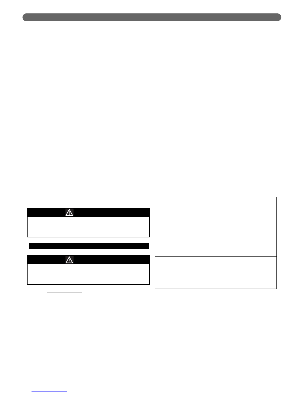
5. Background Information Regarding Draft:
Modern boilers operate with higher efficiencies than
older boilers. Smaller flueways, as well as bars, pins
and fins are designed into modern boilers to transfer
as much heat as possible from the hot gases to the
water or steam and prevent heat loss up the
chimney. However, these design features result in
higher pressure, or draft loss, in the boiler.
This draft loss must be taken into account when
installing an oil boiler into a new or old chimney.
New chimneys are less likely to have poor draft.
However, they must have sufficient draft to support
combustion. A -0.06" draft is desirable and preferred.
Older chimneys may require a replacement liner to
have them perform well enough to support
combustion.
For Example:
The above readings are "cold" readings (before the
boiler and chimney are heated up).
Note also that the higher the firing rate on a unit
which has multiple firing rates, the higher the draft
required. For example, increasing the firing rate 1/4
gallon may increase the draft loss in a unit by
approximately +0.01".
PREINSTALLATION
Old
Installation
New
Installation
Comments
Chimney
Draft
-0.04" -0.04"
No change, but older
chimneys (especially unlined
ones) have leaks which
reduce draft.
Boiler
Design
Pressure
Drop
+0.01" +0.01"
Required for mandated
efficiency increases.
Draft
Over Fire
-0.03" -0.00"
The old installation would
have had a higher
temperature in the chimney
[as high as 800 degrees vs.
400 degrees F], which would
increase the draft.
Do not install this appliance where corrosive
materials, such as ammonia, chlorine, water softener
salt, etc. are stored.
CAUTION
An oil-fired unit shall be connected to a flue having
sufficient draft at all times, to assure safe proper
operation of the unit.
CAUTION
Page 6

4
D. INSTALLATION SURVEY
For new and existing installations, a Water Installation
Survey or a Steam Installation Survey is available from
P.B. Heat, LLC. The surveys will provide information on
how the boiler works with your specific system and will
provide an overview of boiler system operation in
general.
You can also use this survey to locate system problems
which will have to be corrected. To obtain copies of these
Surveys, contact your PB Heat representative or
download it from PeerlessBoilers.com.
E. PLANNING THE LAYOUT
Prepare sketches and notes of the layout of the
installation. Include boiler location, venting system,
existing piping and wiring. Show existing equipment that
may interfere with installation of new equipment.
PREINSTALLATION
Page 7

5
A. SETTING THE BOILER
1. Provide a level foundation, located as close as
possible to the center of the heating system.
2. Refer to Figure 8.1 for exploded view of boiler while
checking and/or assembling parts of the boiler.
3. On packaged boilers, open burner mounting plate
(item 5) at this time to make certain the target wall
(item 2) is seated in the back of the combustion
chamber. (WBV-04™/WV-05™) Ceramic fiber blanket
base liner (item 3) should be lying flat on bottom of
combustion chamber between target wall and burner
mounting plate. Close burner mounting plate.
4. See clearance information in Section 1,
"Preinstallation."
B. CONNECTING THE FLUE OUTLET
The WBV-03™ and WBV-04™ boiler models may be
installed as a rear flue outlet unit or a top flue outlet unit.
Packaged WBV-03™ and WBV-04™ boiler models are
shipped as rear flue outlet and may be converted. The
WV-05™ boiler model is only available as a top flue
outlet unit. On Knockdown boilers, the flue outlet
components are located in the water trim or steam trim
carton.
1. If converting to a top flue application on a packaged
boiler, remove top jacket panel and remove the large
knockout in the jacket top panel. A stub vent will be
required to extend the vent above the jacket top
panel (not provided).
2. Remove the rear outlet cover plate (Item 13 Figure
8.1) and mount the flue collar to the flue collector
plate (Item 11 Figure 8.1) with the 4 #12 screws.
3. Attach the rear outlet cover plate (item 13) to the
rear outlet opening using four (4) 5/16" bolts and
washers provided.
2. BOILER PLACEMENT AND ASSEMBLY
BOILER PLACEMENT AND ASSEMBLY
Page 8
6
A. GENERAL
1. Follow these instructions closely in order to be sure
that the boiler operates as it is intended. Water piping
is extremely important to the system operation.
2. Size water supply and return piping in accordance
with system requirements.
3. If the WBV/WV™ boiler is replacing and existing boiler,
make sure that the system piping is thoroughly cleaned
and free from debris before installing this boiler.
4. Install this boiler so that the oil burner and limit
controls are protected from water (dripping,
spraying, etc.) during operation and service.
5. The WBV/WV™ boiler is designed to operate in a
closed loop hydronic system under forced circulation.
However, there is no minimum water flow rate for
this boiler.
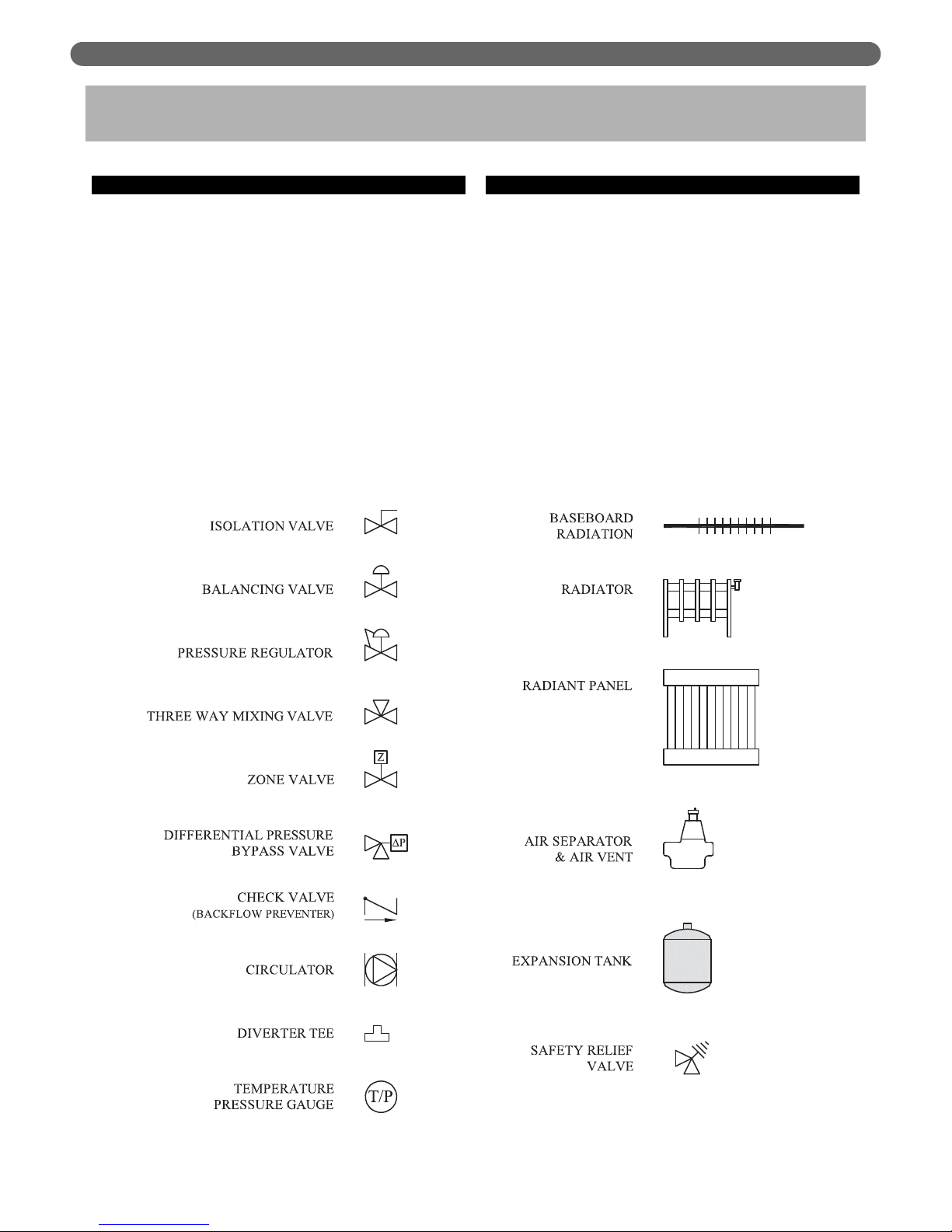
B. SYSTEM COMPONENTS
Figure 3.1 shows the symbol key for the piping diagrams
in this section. The following are brief descriptions of
system components.
1. Pressure/Temperature Gauge: A combination
pressure/temperature gauge is provided with each
WBV/WV™ boiler to be mounted in the supply
(outlet) piping as shown in figure 3.2. Most local
codes require this gauge.
2. Air Elimination: Closed loop hydronic systems
require air elimination devices. As the system water
is heated, dissolved oxygen and other gases will
separate from the liquid. An air elimination device
(such as a TACO Vortech Air Separator) is required
to remove the dissolved gases preventing corrosion
in the piping system and eliminating noise.
3. WATER PIPING
WATER PIPING
Figure 3.1: Symbol Key
Page 9

7
3. Expansion Tank: An expansion tank (such as a Bell
& Gossett Series HFT) is required to provide room
for expansion of the heating medium (water or glycol
solution). Consult the expansion tank manufacturer’s
instruction for specific sizing information. The
expansion tank is to be sized for the required system
volume and capacity. In addition, care must be taken
to size the expansion tank based on the proper
heating medium. Glycol solutions may expand more
than water for a similar temperature rise. Table 3.1
shows the approximate water volume of the boiler
for sizing the expansion tank and determining glycol
solution concentration.
4. Flow Control Valve (Check Valve): Flow control
valves or check valves are used to prevent gravity
circulation by incorporating a weighted disc into the
check valve. These valves also prevent problems with
reverse circulation through parallel heating loops
which cause erratic behavior of the heating system
and prevent heat from reaching its intended load.
5. Pressure Reducing Valve: A pressure reducing valve,
such as the Bell & Gossett B-38 or a TACO #29, is
used in a hydronic system to automatically feed
water to the system whenever the pressure drops
below the set pressure. These valves should not be
used on glycol systems unless close supervision of
the glycol solution is practiced.
6. Back Flow Preventer: A back flow preventer (check
valve) is required by some jurisdictions to prevent
water in the hydronic system from backing up into
the city water supply if the supply pressure drops
below that of the heating system. This is especially
important on systems in which glycol solution is used
as a heating medium.
7. Pressure Relief Valve: The boiler pressure relief valve
is shipped separately for field installation. On the
WBV/WV™ boiler, this can be piped into the
connection provided next to the boiler supply (outlet)
connection or, alternatively, on the connection at the
rear of the boiler below the supply. The value is to
be installed as shown in Figure 3.2.
Pipe the discharge of the safety relief valve to within
12" of the floor and close to an open drain. The
discharge piping must be the same size or larger than
the relief valve outlet. DO NOT INSTALL A CAP OR
VALVE AT THE RELIEF VALVE OUTLET.
8. Circulator: Circulators for central heating distribution
should be sized and installed in accordance with
system requirements and pump manufacturers
recommendations.
9. Indirect Water Heater: An indirect water heater should
be piped to a dedicated zone as shown in Figure 3.3.
10. Boiler Drain Valve: Fittings are provided for
mounting the boiler drain valve in the return tapping
at the bottom rear of the boiler. See Figure 3.4. It is
recommended that the boiler return be piped to the
rear of the block, however for a front return locations
see Figure 3.5.
WATER PIPING
Figure 3.2: Pressure/Temperature Gauge & Relief
Valve Piping
Boiler Model Water Volume, Gal (Liter)
WBV-03 11.75 (44.5)
WBV-04 14.75 (55.8)
WV-05 17.75 (67.1)
Table 3.1: Boiler Water Volume
Do not operate this appliance without installing the
pressure relief valve supplied with the boiler or one
with sufficient relieving capacity in accordance with
the ASME Rating Plate on the boiler.
WARNING
Pipe the discharge of the relief valve as close as
possible to the floor and away from high traffic areas.
Pipe the discharge close to a floor drain. Failure to
do so may result in personal injury and/or property
damage.
CAUTION
The relief valve must be mounted in a vertical upright
position. No other valve or restriction is to be
installed in this line.
CAUTION
Page 10

8
WATER PIPING
Figure 3.3: Recommended Water Piping
Page 11

9
WATER PIPING
C. SYSTEM PIPING
1. The WBV/WV Plastic Jacket boiler is recommended
to be piped with the return line in the rear. The
return can be moved to the front of the boiler by
moving the plug from the front return port to the
rear. The necessary componets for a front return are
included with the boiler.
2. Figure 3.3 shows the recommended piping for the
WBV/WV™ boiler.
3. The DHW zone is piped from the primary loop in
parallel with the central heating (CH) zones. It should
be piped as close to the boiler as possible since it
should be the hottest zone.
D. FREEZE PROTECTION
Glycol for hydronic applications is specially formulated
for heating systems. It includes inhibitors which prevent
the glycol from attacking metallic system components.
Make sure that the system fluid is checked for correct
glycol concentration and inhibitor level.
E. SPECIAL APPLICATIONS
1. If the WBV/WV™ boiler is used in conjunction with a
chilled medium system, pipe the chiller in a separate
secondary loop as shown in Figure 3.6.
2. If using the WBV/WV™ with a hot water coil in a
forced air system, be sure the hot water coil is
downstream of the cooling coil in the airstream.
F. TANKLESS HEATER OR COVERPLATE
1. If a tankless coil is used (item 9), install as pictured.
On water boilers, install in opening in front section.
2. If not using a tankless coil, cover the heater opening
with cover plate (item 7 or 16).
G. CONTROLS
1. Water Boiler Controls:
a. For installations subject to UL726, a second
operating control that senses water temperature
is also required (not provided). Use an L4080B
or equivalent. Install in the supply piping near
the boiler.
2. For complete information on servicing and
adjustment of controls, refer to the attached control
specification sheets.
Figure 3.4: Recommended Near Boiler Piping for
Rear Return
Figure 3.5: Optional Near Boiler Piping for Front
Return
DANGER
Install anti-scald device in hot water supply piping.
Water temperature above 125°F can cause severe
burns instantly or death from scalds.
X1019R and X1020R coils installed in WBV™ boilers
have internal flow controls installed. Do not use
external flow controls with these coils.
NOTICE
Be sure rubber gasket is in place between cover
plate or water heater plate and boiler section.
NOTICE
Pipe the discharge of the safety valve or relief valve
to prevent injury in the event of pressure relief. Pipe
the discharge to a drain. Provide piping that is the
same size as the relief valve.
CAUTION
Page 12

10
Figure 3.7: Tankless Coil Piping, Water Boiler
WATER PIPING
Figure 3.6: WBV/WV™ Piped with a Chiller
Page 13

11
BURNER SETUP & BOILER OPERATION
A. BURNER INSTALLATION
1. The oil burner is supplied with a mounting flange
fixed in position.
2. Mount the burner to the burner mounting plate (Item
5 Figure 8.1) with four (4) 5/16" studs and nuts
provided.
3. Pipe the oil lines through the holes in the left side of
the jacket. Care must be taken when routing the oil
lines so not to interfere with the opening and closing
of the burner mounting plate. Flexible oil lines or
flared copper disconnects with valves (when copper
lines are used) may be installed to assure full opening
of the burner mounting plate when servicing.
4. Oil burner specifications:
For information pertinent to the oil burner such as
nozzle sizing, fuel supply piping, adjusting or
servicing, refer to the charts in this section and the
burner installation manual.
B. BURNER START-UP AND ADJUSTMENT
1. Burner should start automatically when thermostat is
turned up and main boiler service switch is turned on.
If burner does not start, check to be sure there is oil in
the tank and push reset button on burner control:
Beckett: Square red button.
Carlin: Round red button.
Riello: Round red button inside clear flexible
cover on back of burner cover.
If burner still does not start, contact serviceman.
2. Adjust burner and barometric draft control for
highest CO²(Maximum 13%) while maintaining a 0
Smoke and -.01 to -.02" W.C. draft overfire.
All adjustments must be made using suitable
instruments such as found in a Bacharach
Combustion Test Kit.
3. Burner and boiler can be shut down by turning
down the thermostat and moving the main boiler
service switch to the "off" position.
4. See burner manufacturer’s manual for further
information regarding the burner.
C. CHECK BOILER CONTROLS
1. Limit and Operating Controls:
a. Lower the set point of each control until the
burner shuts down. Note that the system pressure
(or temperature) corresponds to the desired set
point.
b. Return the controls to the desired set point.
2. Low Water Cut-off (Built in to limit control.) - consult
the manufacturer's instructions for the low water cutoff operational check procedure.
3. Refer to Limit Control Man. Instrucitons for further
information.
4. BURNER SETUP & BOILER OPERATION
This appliance is designed to burn only standard No.
1 or No. 2 Fuel Oil (ASTM D396). Do not use gasoline
or waste oil.
CAUTION
Do not use compression fitting for oil supply lines.
Do not use copper sweat fittings with oil piping. Oil
leaks may occur causing a fire hazard.
CAUTION
Oil piping must be air tight. Air leaking into the oil
supply system may cause erratic burner operation
and/or burner lockout.
NOTICE
Be sure high temperature gasket is between the
burner mounting flange and the burner mounting
plate.
NOTICE
Two-pipe oil supply for Riello burner requires a
separate kit. Order part #C7001026 from Riello dealer.
NOTICE
Do not attempt to start the burner when excess oil
has accumulated, when the unit is full of vapor, or
when the combustion chamber is very hot.
CAUTION
Do not attempt to set up the burner without using
test instruments. Visual and auditory inspection can
not be trusted to assure proper operation. Failure to
check and adjust combustion using combustion test
instruments may result in severe personal injury,
death or major property damage.
WARNING
Page 14

12
D. PURGE AIR FROM THE SYSTEM
(WATER BOILERS ONLY)
1. Purge the system using purge valves, isolating zones
in the process or use system vents. Do not operate the
pump(s) while purging. Pumps will hold air in the eye
of the impeller.
2. Allow the system to reach 180°F and use manual
vents, if installed, to remove any remaining air. Watch
the pressure gauge as the system approaches 180°F. If
the pressure exceeds the design operating pressure,
check:
a. Fill valve pressure.
b. Expansion or compression tank operation and
sizing.
BURNER SETUP & BOILER OPERATION
Page 15

13
BURNER SETUP & BOILER OPERATION
BECKETT BURNER SPECIFICATIONS
Boiler
Model No.
Burner
Model No.
Burner
Head
Static
Plate
Nozzle Size
Pump
Pressure
Start-up Settings
Head
Setting
Air Shutter Air Band
WBV-03-085 AFG-F3¹ F3 3-3/8" 0.75 80° B HAGO³ 140 PSI 6.0 1 N/A
WBV-03-105 AFG-F4 F4 3-3/8" 0.90 80° B HAGO 140 PSI 6.0 0 N/A
WBV-04-095 AFG-F4 F4 3-3/8" 0.85 80° B DEL
4
140 PSI 6.0 0 N/A
WBV-04-125 AFG-F4 F4 3-3/8" 1.10 80° B HAGO³ 140 PSI 5.0 2 N/A
WBV-04-150 AFG-F6 F6 2-3/4" 1.25 80° B HAGO 140 PSI 8.0 1 N/A
WV-05-175 AFG-MV1 V- 1 - 1.50 60° B HAGO³ 140 PSI 10.0 3 3
WV-05-195 AFG-MV1 V- 1 - 1.65 60° B HAGO 140 PSI 10.0 9 3
CARLIN BURNER SPECIFICATIONS (WITH 98022 PSC MOTOR)
Boiler
Model No.
Burner
Model No.
Head Bar Nozzle Size Pump Pressure
Start-up Settings
Air Shutter Air Band
WBV-03-085 EZ-1HP 0.60 - 0.65 0.65 70° A DEL³ 150 PSI Blank 0.60
WBV-03-105 EZ-1HP 0.85 - 1.00 0.85 70° A DEL 150 PSI Blank 0.65
WBV-04-095 EZ-1HP 0.75 0.75 70° A DEL
4
150 PSI Blank 0.60
WBV-04-125 EZ-1HP 0.85 - 1.00 1.00 70° A DEL³ 150 PSI Blank 0.85
WBV-04-150 EZ-1HP 1.10 - 1.25 1.25 60° B DEL 150 PSI Blank 1.00
WV-05-175 99FRD N/A 1.50 60° B HAGO³ 150 PSI Open 10% open
WV-05-195 99FRD N/A 1.65 60° B HAGO 150 PSI Open 45% open
RIELLO BURNER SPECIFICATIONS
Boiler
Model No.
Burner
Model No.
Burner Series Nozzle Size² Pump Pressure
Start-Up Settings
Turbulator Air Damper
WBV-03-060 F3 Series 40 0.50 90° B 145 PSI 0.0 2.9
WBV-03-085 F5 Series 40 0.65 60° W³ 170 PSI 1.0 2.45
WBV-03-105 F5 Series 40 0.85 60° W 165 PSI 2.5 2.8
WBV-04-095 F5 Series 40 0.75 80° B
4
160 PSI 0.5 2.25
WBV-04-125 F5 Series 40 1.00 60° W³ 155 PSI 2.5 3.4
WBV-04-140 F5 Series 40 1.10 60° W 160 PSI 4.0 4.2
WV-05-175 F10 Series 40 1.35 60° B³ 165 PSI 2.0 2.5
WV-05-195 F10 Series 40 1.50 60° B 170 PSI 2.5 2.8
Factory Installed Nozzles (Packaged Boilers or Burner Cartons) are indicated in Boldface.
1 Requires Low Firing Rate Baffle
2 Delavan Recommended
3 Shipped Loose with Packaged Boiler or Burner Carton
4 Not included with Packaged Boiler or Burner Carton
Table 5.1: Beckett Burner Specifications
Table 5.2: Carlin Burner Specifications (with 98022 PSC motor)
Table 5.3: Riello Burner Specifications
BECKETT NX BURNER SPECIFICATIONS
Boiler Model No. Burner Model Nozzle Size Pump Pressure Start Up Head/Air
WBV-03-085 NX70LB 0.65 x 60° W DEL³ 170 1.5
WBV-03-105 NX70LB
0.85 x 60° B HAGO
170 2.5
WBV-04-095 NX70LB 0.75 x 60° W DEL
4
170 2.0
WBV-04-125 NX70LD 1.10 x 60° W DEL³ 140 1.0
WBV-04-150 NX70LD 1.25 x 60° W DEL 140 2.0
Note: Burner used to fire the WBV-03-085 and 1.05 rate is also required to fire the WBV-04-095 rate with nozzle indicated in above chart.
Page 16

14
A. GENERAL
All electrical wiring shall be done in accordance with the
National Electrical Code and Local Requirements. Single
pole switches including those of safety controls or
protective devices shall not be wired in a grounded line.
B. WIRING
1. See Section 4 for mounting burner.
2. For complete information on servicing and
adjustment of controls, refer to the attached control
specification sheets.
3. See the following Wiring Diagrams:
Figure 5.1 - Water Boilers, Beckett 7600A
Limit Control
Figure 5.2 - Water Boilers, Hydrolevel 3250
Limit Control
5. ELECTRICAL
ELECTRICAL
Page 17

15
ELECTRICAL
Figure 4.1: Water Boilers, Beckett 7600A Limit Control
Figure 4.1a: Beckett AquaSmart 7600A Limit Control Wiring Details
Page 18

16
Figure 4.2: Water Boilers, Hydrolevel 3250 Limit Control
ELECTRICAL
Figure 4.2a: Hydrolevel HydroStat 3250 Limit Control Wiring Details
Page 19

17
MAINTENANCE
6. MAINTENANCE
WARNING
Product Safety Information
Refractory Ceramic Fiber Product
This appliance contains materials made from refractory ceramic fibers (RCF). Airborne RCF,
when inhaled, have been classified by the International Agency for Research on Cancer
(IARC), as a possible carcinogen to humans. After the RCF materials have been exposed to
temperatures above 1800°F, they can change into crystalline silica, which has been classified
by the IARC as carcinogenic to humans. If particles become airborne during service or
repair, inhalation of these particles may be hazardous to your health.
Avoid Breathing Fiber Particulates and Dust
Suppliers of RCF recommend the following precautions be taken when handling these
materials:
Precautionary Measures:
Provide adequate ventilation.
Wear a NIOSH/MSHA approved respirator.
Wear long sleeved, loose fitting clothing and gloves to prevent skin contact.
Wear eye goggles.
Minimize airborne dust prior to handling and removal by water misting the material and
avoiding unnecessary disturbance of materials.
Wash work clothes separately from others. Rinse washer thoroughly after use.
Discard RCF materials by sealing in an airtight plastic bag.
First Aid Procedures:
Inhalation: If breathing difficulty or irritation occurs, move to a location with fresh clean air.
Seek immediate medical attention if symptoms persist.
Skin Contact: Wash affected area gently with a mild soap and warm water. Seek immediate
medical attention if irritation persists.
Eye Contact: Flush eyes with water for 15 minutes while holding eyelids apart. Do not rub
eyes. Seek immediate medical attention if irritation persists.
Ingestion: Drink 1 to 2 glasses of water. Do not induce vomiting. Seek immediate medical
attention.
Page 20

18
MAINTENANCE
A. GENERAL
1. Check pipes adjacent to cold walls or in unheated
spaces. Insulate and tape them if necessary to be
sure they can't freeze up. Keeping the water moving
at all times will reduce the likelihood of freezing.
2. If there is considerable foreign matter in the boiler
water, the boiler should be shut down and allowed to
cool, then drained and thoroughly flushed out. Drain
the boiler at the drain cock. Pipe the drain cock to a
suitable drain or containment device (if antifreeze is
used). Flush the system to remove remaining matter.
If there is evidence that hard scale has formed on the
internal surfaces, the boiler should be cleaned by
chemical means as prescribed by a qualified water
treatment specialist.
3. There must be no signs of continuous wetness at the
chimney. If signs of continuous wetness are
observed, a qualified service agency must be
consulted to modify the vent configuration to prevent
the formation of condensate, which may damage the
vent pipe.
B. DAILY MAINTENANCE (WITH BOILER
OPERATING)
Daily boiler observation can be performed by the owner.
If any potential problems are found, a qualified installer
or service technician/agency must be notified.
1. Remove any combustible materials, gasoline and
other flammable liquids and substances that generate
flammable vapors from the area where the boiler is
contained. Make certain that the boiler area has
ample air for combustion and ventilation and that
there are no obstructions to the free flow of air to
and from the boiler.
2. Observe general boiler conditions (unusual noises,
vibrations, etc.)
3. Observe operating temperature and/or pressure
gauge on the boiler. Boiler pressure should never be
higher than 5 psi below the rating shown on the
safety relief valve. The valve rating can be found on
the top of the safety relief valve. Boiler temperature
should never be higher than 250°F.
4. Check for water leaks in boiler and system piping.
C. WEEKLY MAINTENANCE (WITH BOILER
OPERATING)
1. Flush float-type low-water cut-off (if used) to remove
sediment from the float bowl as stated in the
manufacturer's instructions.
D. MAINTENANCE OF SAFETY RELIEF
VALVE
1. Check function and maintain safety relief valve as
specified by manufacturer, typically every other
month or every month, per the instructions on the
tag on the safety relief valve.
E. MONTHLY MAINTENANCE (WITH BOILER
OPERATING)
1. Check boiler room floor drains for proper
functioning.
2. Test probe type low-water cut-off (if used) by using
the Push-to-Test Button.
3. Test limit by lowering the limit set point until the
burner shuts down. When proper operation is
confirmed, return the set point to original setting.
4. Follow additional instructions in the Burner Manual
for proving the burner component operation.
F. MAINTENANCE – ANNUAL
TO CLEAN:
1. Remove top jacket panel and flue collector cover
plate, Item 11 (Figure 2.1).
2. To thoroughly clean the boiler it must be brushed
down from the top. The target wall is made of a soft
ceramic fiber. Care must be taken not to damage this
material during cleaning.
3. Remove any scale or soot from the combustion
chamber area by vacuum cleaning or any other
available means.
Do not use this appliance if any part has been under
water. Improper or dangerous operation may result.
Immediately call a qualified service technician to
inspect the boiler and to replace any part of the
control system and any control which has been
under water.
WARNING
Entire heating system, including boiler, burner and
venting system, must be inspected at least once a
year by a qualified heating professional. Boiler is to
be cleaned at least once a year.
NOTICE
Burner mounting plate must be opened gain access
to combustion chamber for the removal of dirt and
debris.
NOTICE
Disconnect all power to the burner before accessing
combustion chamber.
WARNING
Page 21

19
MAINTENANCE
4. Inspect the insulation and rope seal on the burner
mounting plate. Replace if damaged.
5. Replace oil burner and flue collector cover plate
making sure all gaskets are in place.
6. Replace jacket top panel.
7. Check the ventilation system for signs of external
corrosion.
8. Disassemble exhaust vent and air inlet (if applicable)
connections to check for blockage and/or corrosion.
9. Assure that barometric damper swings freely.
G. WATERSIDE INSPECTION
1. Connect a suitable drain hose to the boiler drain
valve. Have a 5 gallon bucket available to catch
boiler water.
2. Be sure that the system temperature is below 125° F
before draining water from the system.
3. Drain water from the boiler into the bucket. If there
is evidence of excessive sediment/sludge in the
system, contact a qualified water treatment company
for appropriate compounds such as Sentinel X-400
or Rhomar Hydro-Solve 9100.
H. INSPECT HEAT DISTRIBUTION SYSTEM
1. Check all visible water piping for signs of water leaks
(corrosion scale or scale staining).
2. Check the boiler system pressure to be sure it is at
the required pressure. Open the city water inlet valve
to assure required system pressure (usually about 12
psi). Close the inlet valve (if it is necessary to open
the inlet water valve frequently, a substantial leak
may be the cause).
3 Repair any leaks to the system to prevent corrosion
and scale in the boiler.
I. IF A LONG SHUTDOWN IS REQUIRED
1. To take boiler out of service if the boiler and system
are not to be used when temperatures are below
freezing:
a. Drain the boiler and system completely and shut
off make-up water supply.
b. Open main line power disconnect switch to
boiler. Remove the fuses or secure the switch so
that the power cannot be turned on accidentally.
2. Be certain that the boiler and system are refilled
before returning to service.
All cover plates, enclosures, and guards must be
maintained in place at all times, except during
maintenance and servicing.
NOTICE
Water in excess of 125° F can cause severe burns
instantly. DO NOT drain water in excess of 125° F
from the boiler. Failure to comply may cause severe
injury or death.
WARNING
The Peerless Warranty does not cover sediment or
corrosion related damage. Excessive sediment may
cause a failure of the boilers cast iron heat exchanger.
CAUTION
Always keep the manual fuel supply valve shut off if
the burner is shut down for an extended period of
time.
CAUTION
Page 22

20
BOILER DIMENSIONS & RATINGS
7. BOILER DIMENSIONS & RATINGS
Figure 7.1: Boiler Dimensions, Water Boiler
Boiler
Model
Number
Jacket
Depth
"A"
Jacket
Width
"B"
Jacket
Height
"C"
Rear of Jacket
to c/l of Vent
"D"
Vent Size
Diameter
"E"
WBV-03-085/110 18-3/8" 23-5/8" 39-1/4" 7" 6"
WBV-04-125/150 22-3/8" 23-5/8" 39-1/4" 11" 6"
WV-05-175/200 26-3/8" 23-5/8" 39-1/4" 15" 7"
Page 23

21
Table 7.1: Boiler Ratings
✸ As an ENERGY STAR
®
Partner, PB Heat, LLC has determined that these firing rates meet the ENERGY STAR guidelines for energy efficiency.
✝ Top venting only.
✚
Nozzles for these firing rates not provided as standard equipment. Consult factory for price and availability.
✪ This firing rate can only be achieved with a Riello F-3 burner. See Table 5.3.
1 Burner input based on No. 2 fuel oil with a heating value of 140,000 Btu per gallon.
2 Net water ratings based on an allowance of 1.15.
3 Consult factory before selecting a boiler for installations having unusual piping and pickup requirements, such as intermittent system operation, extensive
piping systems, etc.
4 Heating Capacity and Annual Fuel Utilization Efficiency (AFUE) ratings are based on U.S. Government tests, with 13% CO
2
and –0.02" w.c. draft over fire.
Before purchasing this appliance, read important information about its estimated annual energy consumptions or energy efficiency rating that is available from
your retailer.
5 Chimney Size: 8" x 8" x 15 ft.
BOILER DIMENSIONS & RATINGS
Series WBV/WV™
Boiler
Model
Number
Input
Heating
Capacity4,
MBH
Net Ratings
3
AFUE,
%
GPH¹ MBH Water
Water,
MBH² Water
WBV-03 0.60
✚✪
84 75 65 87.5
✸
WBV-03 0.85 119 104 90 86.2
WBV-03 1.05 147 126 110 85.0
WBV-04 0.95
✚
133 117 102 87.0
✸
WBV-04 1.25 175 151 131 85.4
WBV-04 1.50 210 180 156 85.1
WV-05
✝
1.75 245 212 184 85.5
WV-05
✝
1.95 273 235 204 85.0
Water
Content,
gal
Minimum
Stack
Draft
Required,
in. W.C.
11.75 -0.03
11.75 -0.04
11.75 -0.05
14.75 -0.03
14.75 -0.04
14.75 -0.05
17.75 -0.05
17.75 -0.06
SERIES WBV/WV™ BOILER RATINGS
Page 24

22
REPAIR PARTS
8. REPAIR PARTS
Repair parts are available from your local PB Heat, LLC distributor or from Parts To
Your Door at 1 (610) 916-5380 (www.partstoyourdoor.com).
Note: Remember to include the boiler model number and serial number when ordering parts.
Figure 8.1: Water boiler
Page 25

23
Table 8.1
Part numbers may be subject to change without notice.
*See Figure 8.1 boiler exploded view.
Item
No.*
Description
Additional
Information
Stock
Code
1
Block Assembly – Water – WBV-03( Open)
–
90815
Block Assembly – Water – WBV-04 (Open)
–
90824
Block Assembly – Water – WV-05 (Open)
–
91085
Block Assembly – Water – WBV-03 (Closed)
–
90806
Block Assembly – Water – WBV-04 (Closed)
–
90813
Block Assembly – Water – WV-05 (Closed)
–
91088
2 Target Wall
–
50795
4 Swing Door Hinge
–
90538
5 Burner Mounting Plate Assembly
–
91278
–
Burner Mounting Plate Insulation
–
50796
6 Burner Mounting Plate Rope Seal
–
51211
7 Steel Cover Plate (Front) – Water
–
99812
8 Rubber Gasket (Front) – Water
–
51800
9
Tankless Coil – WBV-03 – Water
–
90637
Tankless Coil – WBV-04 – Water
–
90534
Tankless Coil – WV-05 – Water
–
90534
10 Flue Collector Plate Blanket Seal
–
90999
11 Flue Collector Cover Plate – WBV-03
–
90565
–
Flue Collector Cover Plate – WBV-04
–
90566
11A Top Outlet Flue Collector Plate – WV-05
–
90562
12 Rope Seal
–
51209
13 Rear Outlet Cover Plate
–
90563
14 Flue Collar Adapter – WBV-03 & 04 – Water
– 90568
15
Plastic Jacket Assembly – Water – WBV-03
–
54525
Plastic Jacket Assembly – Water – WBV-04
–
54526
Plastic Jacket Assembly – Water – WV-05
–
54652
16 Jacket Support Frame
–
54524
17 Upper Plastic Cover
–
54479
18 Flue Outlet Gasket
–
PP5011
19 Lower Plastic Cover 54480
20 Plastic Lens 54508
–
Drain Valve
–
50764
–
Relief Valve – Water
–
50501
–
Bracket/Sensor Assembly HydroStat
–
50835
–
Insulation Hardware PJKT
–
91217
–
Limit Control, Beckett AquaSmart 7600A
–
50338
–
Immersion Well, Beckett 7600T
–
50341
–
Sensor, Beckett 7600P 07B Long
–
50340
–
Limit Control with 24" Sensor, Hydrolevel HydroStat 3250
–
50353
–
Immersion Well, Hydrolevel
–
50723
REPAIR PARTS
Page 26

PP8176 R0 (06/14-5M)
Printed in U.S.A.
WEB-1 (10/14)
©2014 PB Heat, LLC. All rights reserved.
WBV/WV
™
Boilers
Series
Oil
Installation,
Operation &
Maintenance
Manual
TO THE INSTALLER:
This manual is the property of the owner and must
be affixed near the boiler for future reference.
TO THE OWNER:
This boiler should be inspected annually by a
Qualified Service Agency.
Name:
Address:
Phone:
Service Information
PB HEAT, LLC
131 S. CHURCH ST • BALLY, PA 19503
Plastic Jacket
 Loading...