

Page 1
PSC
II
™
Boilers
Series
Gas
Installation,
Operation &
Maintenance
Manual
Page 2

USING THIS MANUAL 1
A. INSTALLATION SEQUENCE . . . . . . . . . . . . .1
B. SPECIAL ATTENTION BOXES . . . . . . . . . . . .1
1. PREINSTALLATION 2
A. ACCESSIBILITY CLEARANCES . . . . . . . . . . .2
B. CLEARANCE FROM COMBUSTIBLE
CONSTRUCTION . . . . . . . . . . . . . . . . . . . . . .2
C. INSTALLATION SURVEY . . . . . . . . . . . . . . . .3
D. PLANNING THE LAYOUT . . . . . . . . . . . . . . . .3
E. MASSACHUSETTS INSTALLATIONS . . . . . .3
2. BOILER SET-UP 4
3. WATER PIPING AND CONTROLS 5
A. BOILER SUPPLY AND RETURN . . . . . . . . . . .5
B. SAFETY RELIEF VALVE . . . . . . . . . . . . . . . . .6
C. PIPING FOR ZONED SYSTEMS . . . . . . . . . .7
D. EXPANSION TANK . . . . . . . . . . . . . . . . . . . . .8
E. INDIRECT-FIRED WATER HEATER . . . . . . . .8
F. FREEZE PROTECTION . . . . . . . . . . . . . . . . . .8
4. VENTING, VENTILATION AND
AIR INLET 9
A. GENERAL . . . . . . . . . . . . . . . . . . . . . . . . . . . .9
B. WALL THIMBLE . . . . . . . . . . . . . . . . . . . . . . .9
C. ROOF TERMINATIONS . . . . . . . . . . . . . . . .11
D. CONDENSATE TRAP INSTALLATION . . . . .11
E. VENT PIPE INSTALLATION . . . . . . . . . . . . .11
F. AIR INLET PIPE INSTALLATION . . . . . . . . .13
G. AIR FOR VENTILATION . . . . . . . . . . . . . . . .13
H. BOILER REMOVAL FROM COMMON
VENTING SYSTEM . . . . . . . . . . . . . . . . . . .13
5. GAS PIPING 15
6. ELECTRICAL 17
A. WIRING . . . . . . . . . . . . . . . . . . . . . . . . . . . . .17
B. ZONED SYSTEM WIRING . . . . . . . . . . . . . .17
C. CONTROLS . . . . . . . . . . . . . . . . . . . . . . . . . .17
D. BOILER SEQUENCE OF OPERATION . . . . .19
7. START-UP PROCEDURES 20
A. COMPLETING THE INSTALLATION . . . . . .20
B. CONTROL DESCRIPTIONS . . . . . . . . . . . . .24
C. ADJUSTMENT OF GAS PRESSURE
REGULATOR . . . . . . . . . . . . . . . . . . . . . . . . .24
D. CHECKING BURNER INPUT . . . . . . . . . . . . .24
E. CHECK-OUT PROCEDURE . . . . . . . . . . . . . .24
8. TROUBLESHOOTING 26
A. SHUT-DOWN CAUSED BY PILOT OUTAGE,
PRESSURE SWITCH OR FLAME ROLL-OUT
SAFETY SHUT-OFF SWITCH . . . . . . . . . . . .26
B. TROUBLESHOOTING GUIDES . . . . . . . . . .26
C. MEASURING SUCTION PRESSURE . . . . . .26
9. MAINTENANCE 29
A. GENERAL . . . . . . . . . . . . . . . . . . . . . . . . . . .30
B. DAILY (WITH BOILER IN USE) . . . . . . . . . . .30
C. WEEKLY (WITH BOILER IN USE) . . . . . . . . .30
D. MONTHLY (WITH BOILER IN USE) . . . . . . .30
E. ANNUALLY (BEFORE START OF HEATING
SEASON) . . . . . . . . . . . . . . . . . . . . . . . . . . .30
10. BOILER DIMENSIONS & RATINGS 33
11. REPAIR PARTS 34
TABLE OF CONTENTS
TABLE OF CONTENTS
Page 3
A. INSTALLATION SEQUENCE
Follow the installation instructions provided in this
manual in the order shown. The order of these
instructions has been set in order to provide the installer
with a logical sequence of steps that will minimize
potential interferences and maximize safety during
boiler installation.
B. SPECIAL ATTENTION BOXES
Throughout this manual you will see special attention
boxes intended to supplement the instructions and make
special notice of potential hazards. These categories
mean, in the judgment of PB Heat, LLC:
1
USING THIS MANUAL
Indicates special attention is needed, but not directly
related to potential personal injury or property
damage.
NOTICE
Indicates a condition or hazard which will or can
cause minor personal injury or property damage.
CAUTION
DANGER
Indicates a condition or hazard which will cause
severe personal injury, death or major property
damage.
USING THIS MANUAL
Indicates a condition or hazard which may cause
severe personal injury, death or major property
damage.
WARNING
Page 4
A. ACCESSIBILITY CLEARANCES
Install boiler not less than 24" (610 mm) between the left
side, top, and front of the boiler and adjacent wall or
other appliance, when access is required for servicing.
B. CLEARANCE FROM COMBUSTIBLE
CONSTRUCTION
The design of this boiler is certified for closet installation
with the following clearances:
1. 6" (152 mm) between right side, front and
combustible construction.
2. 12" (305 mm) between top of jacket and combustible
construction.
3. 1" (25 mm) between left side, rear and combustible
construction.
4. 2" (51 mm) between vent pipe and combustible
construction.
5. Zero clearance between wall thimble and combustible
construction.
6. This boiler is design certified for use on combustible
flooring.
2
PREINSTALLATION
1. PREINSTALLATION
Do not install this boiler on carpeting. Boiler
installation on carpeting is a fire hazard. Install this
boiler on non-combustible flooring or use a
combustible floor pan to install this boiler on other
non-carpeted flooring.
DANGER
Liquefied Petroleum (LP) is heavier than air and may
collect or “pool” in a low area in the event of a leak
from defective equipment. This gas may then ignite,
resulting in a fire or explosion.
WARNING
Read carefully, study these instructions before beginning work.
This boiler must be installed by a qualified contractor.
The boiler warranty can be voided if the boiler is not installed, maintained and serviced correctly.
The equipment must be installed in accordance with those installation requirements of the authority having
jurisdiction or, in the absence of such requirements, to the current edition of the
National Fuel Gas Code,
ANSI
Z223.1/NFPA 54 and/or CAN/CSA B49.1,
Natural Gas and Propane Installation Code
.
Where required by the authority having jurisdiction, the installation must conform to
American Society of Mechanical
Engineers Safety Code for Controls and Safety Devices for Automatically Fired Boilers,
ANSI/ASME CSD-1.
NOTICE
In accordance with Section 325 (f) (3) of the Energy Policy and Conservation Act, this boiler is equipped with a
feature that saves energy by reducing the boiler water temperature as the heating load decreases. This feature is
equipped with an override which is provided primarily to permit the use of an external energy management
system that serves the same function.
THIS OVERRIDE MUST NOT BE USED UNLESS AT LEAST ONE OF THE FOLLOWING CONDITIONS IS TRUE:
• An external energy management system is installed that reduces the boiler water temperature as the
heating load decreases.
• This boiler is not used for any space heating
• This boiler is part of a modular or multiple boiler system having a total input of 300,000
BTU/hr or greater.
• This boiler is equipped with a tankless coil.
IMPORTANT
Page 5

C. INSTALLATION SURVEY
For new and existing installations, a Water Installation
Survey is available from PB Heat, LLC. The survey will
provide information on how a hot water boiler works with
your specific system and will provide an overview of hot
water system operation in general.
You can also use this survey to locate system problems
which will have to be corrected. To obtain copies of the
Water Installation Survey, contact your PB Heat
representative or download it from PeerlessBoilers.com.
D. PLANNING THE LAYOUT
Prepare sketches and notes of the layout to minimize the
possibility of interferences with new or existing
equipment, piping, venting and wiring. Review limitations
on vent pipe, vent terminal, and air inlet pipe locations
and ventilation air requirements in Section 4.
E. MASSACHUSETTS INSTALLATIONS
Massachusetts requires manufacturers of Side Wall
Vented boilers to provide the following information
from the Massachusetts code:
•
A hard wired carbon monoxide detector with an
alarm and battery back-up must be installed on
the floor level where the gas equipment is to be
installed AND on each additional level of the
dwelling, building or structure served by the side
wall horizontal vented gas fueled equipment.
•
In the event that the side wall horizontally vented
gas fueled equipment is installed in a crawl space
or an attic, the hard wired carbon monoxide
detector with alarm and battery back-up may be
installed on the next adjacent floor level.
•
Detector(s) must be installed by qualified licensed
professionals.
•
APPROVED CARBON MONOXIDE
DETECTORS: Each carbon monoxide detector
shall comply with NFPA 720 and be ANSI/UL
2034 listed and IAS certified.
•
SIGNAGE: A metal or plastic identification plate
shall be permanently mounted to the exterior of
the building at a minimum height of eight (8) feet
above grade directly in line with the exhaust vent
terminal for the horizontally vented gas fueled
heating appliance or equipment. The sign shall
read, in print size no less than one-half (1/2) inch
in size, “GAS VENT DIRECTLY BELOW.
KEEP CLEAR OF ALL OBSTRUCTIONS”.
•
EXEMPTIONS to the requirements listed above:
°
The above requirements do not apply if the
exhaust vent termination is seven (7) feet or
more above finished grade in the area of the
venting, including but not limited to decks and
porches.
°
The above requirements do not apply to a
boiler installed in a room or structure separate
from the dwelling, building or structure used in
whole or in part for residential purposes.
•
This boiler installation manual shall remain with
the boiler at the completion of the installation.
See the latest edition of Massachusetts Code 248 CMR
for complete verbiage and also for additional (non-vent
related) requirements (248 CMR is available online).
If your installation is NOT in Massachusetts, please
see your authority of jurisdiction for requirements that
may be in effect in your area. In the absence of such
requirements, follow the National Fuel Gas Code,
ANSI Z223.1/NFPA 54 and/or CAN/CSA B149.1,
Natural Gas and Propane Installation Code.
Venting System Installation Instructions – See
boiler manual and instructions provided with the
Venting System components. Additional copies may
be obtained from the Venting System Manufacturer by
visiting the following web addresses:
Heat-Fab – www.selkirkcorp.com/heatfab
Z-Flex – www.NovaFlex.com
Pro-Tech – www.protechinfo.com
3
PREINSTALLATION
Page 6

4
1. Provide a sound, level foundation. Locate boiler as
near to the outside wall as possible and centralized
with respect to the heating system.
2. Locate boiler in front of installation position before
removing crate.
4. Separate the wood shipping pallet from the boiler
base by removing two (2) hold-down bolts at each
end of the boiler base.
5. Move boiler into final position.
BOILER SET-UP
2. BOILER SET-UP
Page 7
5
A. BOILER SUPPLY AND RETURN
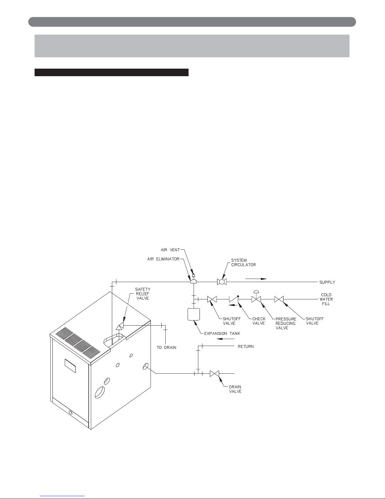
1. Size the supply and return to suit the system. A typical
piping arrangement is shown in Figure 3.1. Refer also
to the Hydronics Institute Residential Hydronic
Heating Installation Design Guide and the PB Heat
Water Survey for additional guidance during water
piping installation.
2. Return Piping:
Pipe the outlet connection of the circulator to a tee,
provided with a drain valve, at the 1-1/4" NPT return
tapping near the bottom of the right section. Pipe the
return to the inlet connection of the circulator.
3. Supply Piping:
a. Pipe the supply to the 1-1/2" NPT supply tapping
at the top of the boiler.
b. Provide clearance to venting system
(see Section 4).
4. When system return water temperature will be below
130°F (54°C), pipe the boiler with a bypass
arrangement to blend the system return and hot
supply to obtain at least 130°F (54°C)entering the
boiler. For more information on bypass piping, consult
the PB Heat Water Survey.
5. If desired, install the circulator in the alternate location
shown in Figure 3.1. Consult the PB Heat Water
Survey for more information on circulator location.
WATER PIPING AND CONTROLS
3. WATER PIPING AND CONTROLS
Figure 3.1: Supply and Return Piping
Page 8
6. Install this boiler so that the gas ignition system
components are protected from water (dripping,
spraying, etc.) during appliance operation and service
(circulator replacement, condensate trap, control
replacements, etc.).
7. If this boiler and distribution system is used in
conjunction with a refrigeration system, pipe the
chilled medium in parallel with the boiler and install
the proper valve to prevent the chilled medium from
entering the boiler. A drawing illustrating this hook-up
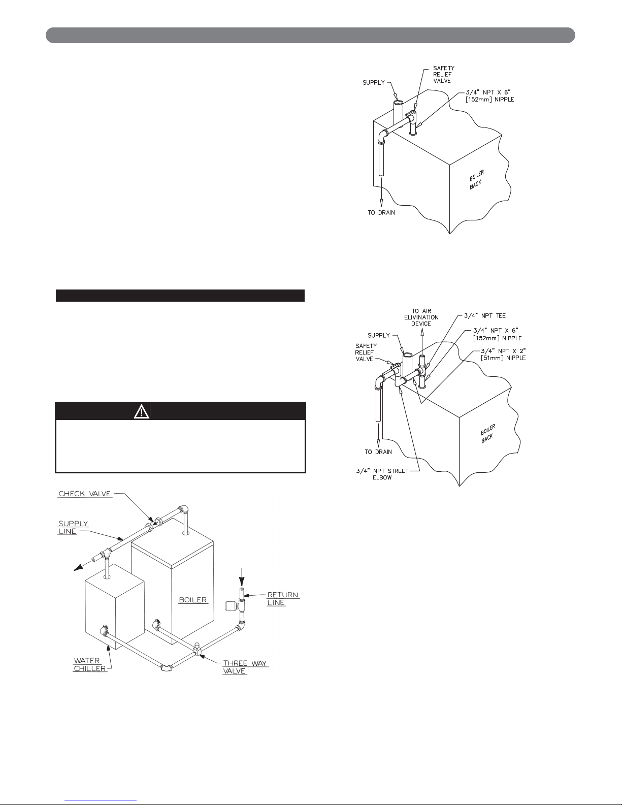
is provided in Figure 3.2.
8. When the boiler is connected to heating coils located
in air handling units where they may be exposed to
refrigerated air circulation, install flow control valves
or other automatic means to prevent gravity
circulation of the boiler water during the cooling cycle.
9. If this boiler is installed above radiation level, provide
a low water cutoff device, either as a part of the boiler
or at the time of boiler installation.
B. SAFETY RELIEF VALVE
1. Locate safety relief valve and fittings in bag assembly.
2. If air elimination is not required at the safety relief
valve tapping, install valve and piping as shown in
Figure 3.3.
3. For air elimination at the safety relief valve tapping,
install valve and piping as shown in Figure 3.4.
6
WATER PIPING AND CONTROLS
Pipe the discharge of safety relief valve to prevent
injury in the event of pressure relief. Pipe the
discharge to a drain. Provide piping that is the same
size as the safety relief valve outlet.
CAUTION
Figure 3.4: Safety Relief Valve Hook-Up with
Air Elimination
Figure 3.3: Safety Relief Valve Hook-Up
Installation with Air Elimination in
System Piping
Figure 3.2: Parallel Hook-up with Water Chiller
Page 9
C. PIPING FOR ZONED SYSTEMS
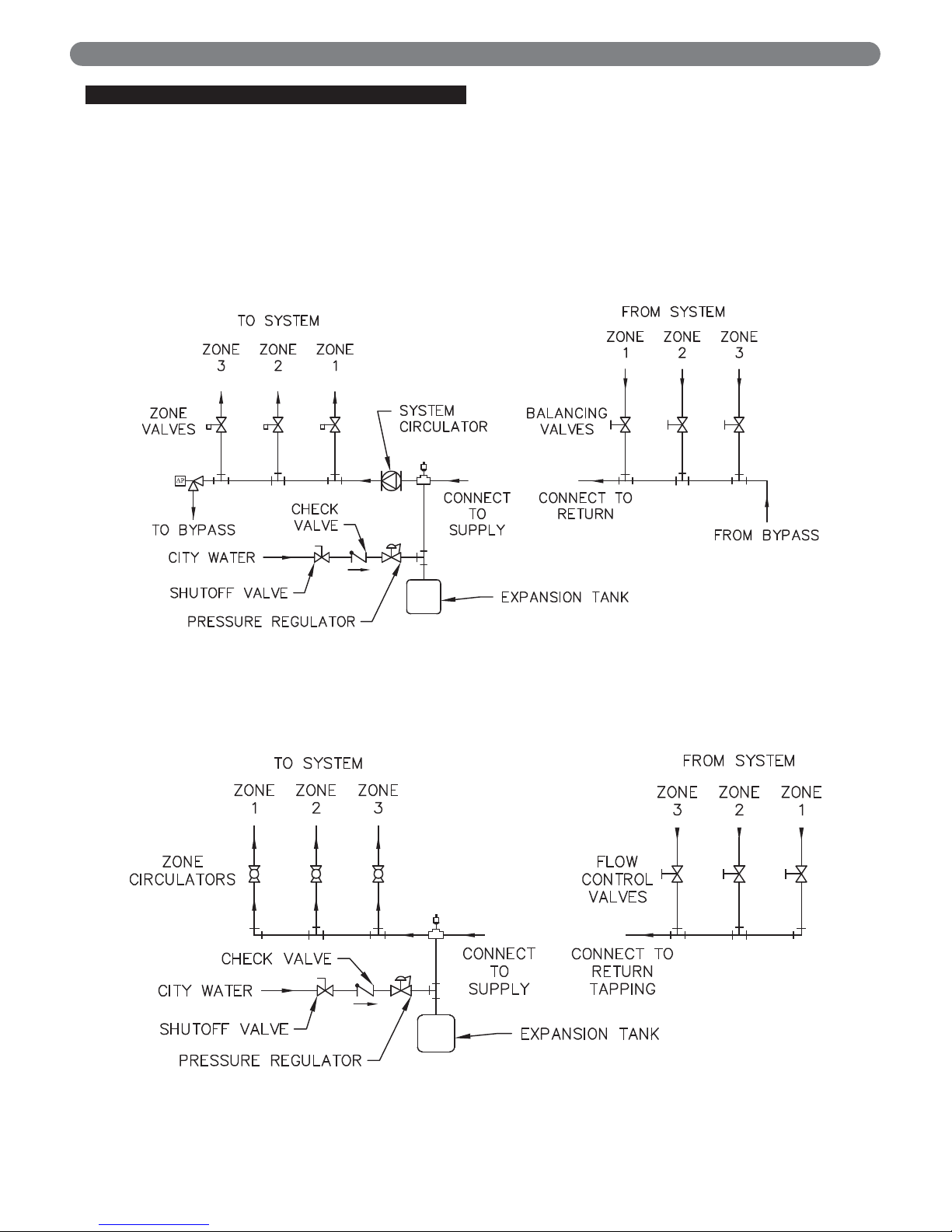
1. See Figures 3.5 and 3.6 for basic zoned system
layouts.
2. Run each zone pipe down then up to zone to prevent
air accumulation in piping.
3. If required, provide means to isolate and drain each
zone separately.
7
WATER PIPING AND CONTROLS
Figure 3.5: Zone Piping with Zone Valves
Figure 3.6: Zone Piping with Circulators
Page 10
8
D. EXPANSION TANK
1. Consult the tank manufacturer’s instructions for
specific information relating to tank installation. Size
the expansion tank for the required system volume
and capacity. See Table 10.2 in Section 10 for boiler
water capacity.
2. Expansion tanks are available with built-in fill valves
and check valves for reducing supply water pressure
and maintaining minimum system pressure. Check the
design features of the tank and provide valves as
necessary.
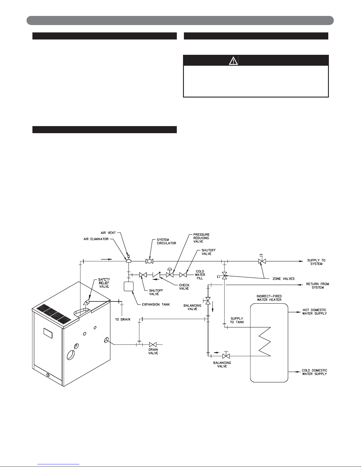
Refer back to Figure 3.1 for typical expansion tank piping.
E. INDIRECT-FIRED WATER HEATER
If the boiler is to be used in conjunction with an indirectfired water heater, refer to Figure 3.7 for typical piping.
Follow the instructions provided by the water heater
manufacturer. Pipe the water heater as a separate zone.
F. FREEZE PROTECTION
For new or existing systems that must be freeze-protected:
1. Glycol in hydronic applications is specially formulated
for this purpose. It includes inhibitors which prevent
the glycol from attacking metallic system components.
Make certain that the system fluid is checked for the
correct glycol concentration and inhibitor level.
2. The glycol solution should be tested at least once a
year and as recommended by the antifreeze
manufacturer.
3. Glycol solutions expand more than water. For
example, a 50% by volume solution expands 4.8% in
volume for a temperature increase from 32°F (0°C) to
180°F (82°C) , while water expands 3% with the same
temperature rise. Allowance must be made for this
expansion in system design.
4. For more information, consult the PB Heat Water
Installation Survey and the antifreeze manufacturer.
A. GENERAL
WATER PIPING AND CONTROLS
Figure 3.7: Typical Piping with Indirect-Fired Water Heater
Use only inhibited propylene glycol solutions of up to
50% by volume with water. Ethylene glycol is toxic
and can attack gaskets and seals used in hydronic
systems.
WARNING
Page 11
A. GENERAL
Install vent system in accordance with Venting of
Equipment part of the National Fuel Gas Code, ANSI
z223.1/NFPA 54 or sections 7.2, 7.3 or 7.4 of CAN/CSA
B149.1, Natural Gas and Propane Installation Code.
B. WALL THIMBLE (SIDEWALL
VENTING ONLY)
1. Determine vent cap (terminal) location.
a. Must be within the maximum and minimum vent
and air intake lengths shown in Tables 4.1 and
4.2.
b. Maximum wall thickness for the 19-1/2" (495 mm)
long Wall Thimble (standard) is 11-1/2" (292 mm).
Maximum wall thickness for the optional 28" (711
mm) long thimble is 20" (508 mm).
c. Provide 2" (51 mm) clearance between vent pipe
and combustible construction. No clearance is
required between Thimble and combustible
construction.
d. Provide 3 feet (1 meter) clearance above any
forced air inlet within 10 feet (3 meters).
e. Provide 1 foot (0.3 meters) clearance below and 1
foot (0.3 meters) beside, or 1 foot (0.3 meters)
above any door, window, or gravity air inlet into
any building.
f. Provide 1 foot (0.3 meters) clearance between
bottom of vent terminal and ground level and
normal snow lines.
g. Provide 4 feet (1.2 meters) horizontal clearance
from electric meters, gas meters, regulators and
relief equipment. In Canada, this dimension must
be 6 feet (2 meters).
h. Do not locate vent terminal over public walkways
where condensate could create a nuisance or hazard.
i. When adjacent to a public walkway, locate vent
terminal at least 7 feet (2.1 meters) above grade.
j. Do not locate directly under roof overhangs to
prevent icicles from forming.
2. Cut a 5-1/8" (130 mm) square hole in sidewall to
allow Peerless
®
Wall Thimble to go through.
3. Insert Thimble from inside wall with 4" (102 mm)
diameter air inlet connection facing down. Extend
Thimble 3-1/2" (89 mm) past outside wall surface.
The cut-out opening of thimble is pointed down.
4. Use a minimum 2-1/2 foot (762 mm) piece of 3"
(76 mm) diameter AL29-4C stainless steel vent pipe
for insertion through Wall Thimble. See Vent Pipe
section below for vent pipe requirements.
VENTING, VENTILATION AND AIR INLET
4. VENTING, VENTILATION AND AIR INLET
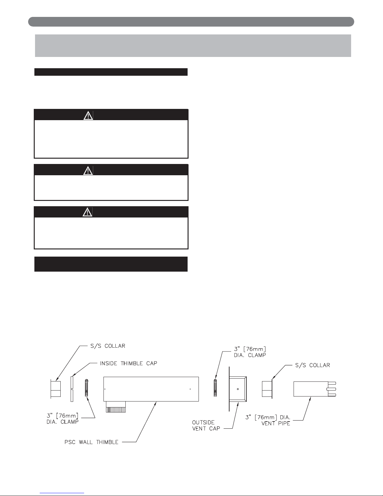
Figure 4.1: Wall Thimble
This vent system will operate with a positive
pressure in the vent pipe. Do not connect vent
connectors serving appliances vented by natural
draft into any portion of mechanical draft systems
operating under positive pressure.
Flue gases will condense as they exit the vent
termination. This condensate can freeze on exterior
building surfaces which may cause discoloration of
these surfaces.
NOTICE
WARNING
WARNING
All joints of positive pressure vent systems must be
sealed completely to prevent leakage of flue products
into the living space.
9
Page 12
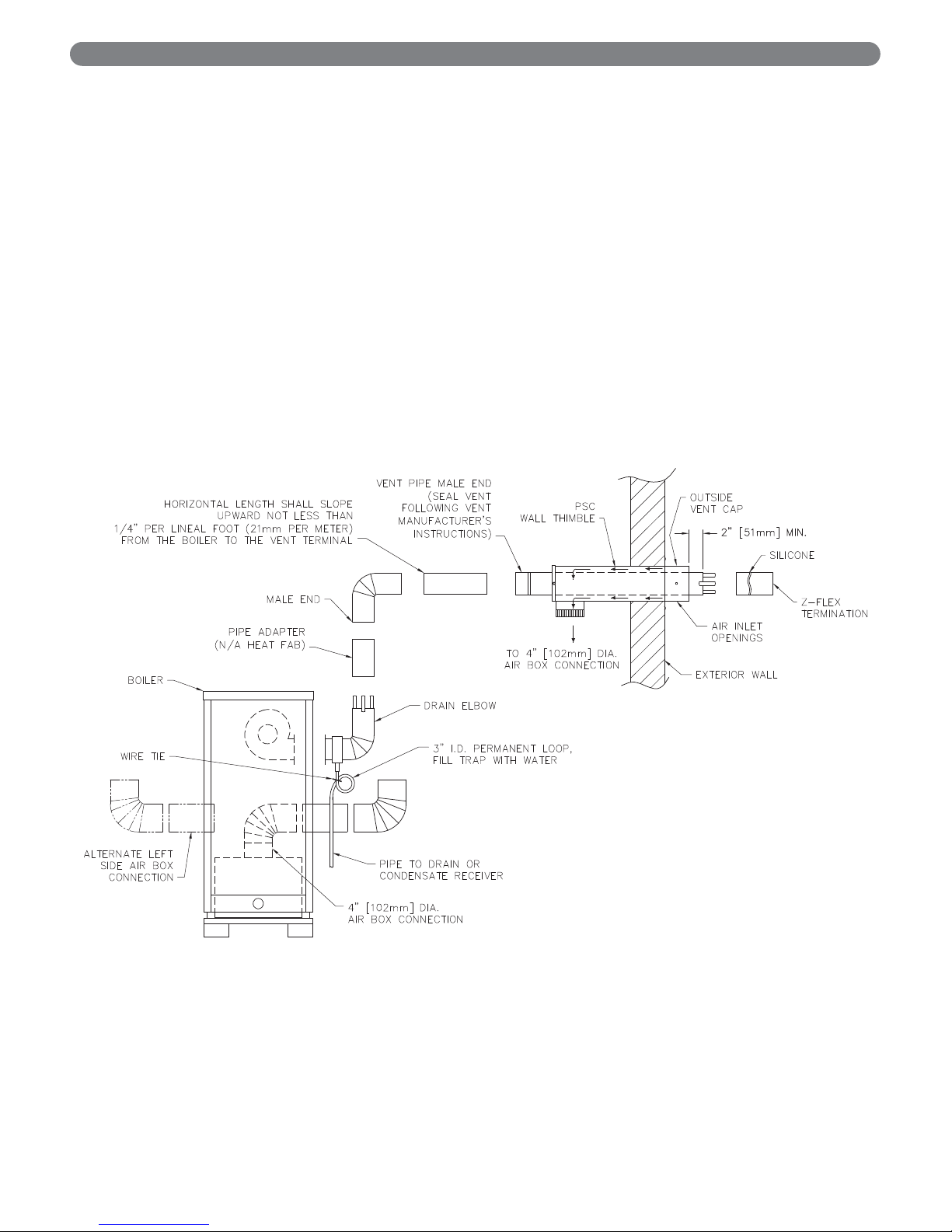
5. Slide Stainless Steel Collar over vent pipe and slide to
end of pipe.
6. Insert pipe with collar through Outside Vent Cap and
slide 3" (76 mm) diameter hose clamp over collar.
7. Leave at least 2" (51 mm) of vent pipe protruding
beyond face of Vent Cap and secure hose clamp and
collar to vent pipe.
8. Place Outside Vent Cap over Wall Thimble with air
openings in Vent Cap facing down. Secure Cap to
Thimble with #10 sheet metal screws.
9. Place 3" (76 mm) diameter hose clamp over pipe
protruding through inside of Wall Thimble.
10. Place Inside Thimble Cap and Collar onto Wall
Thimble. Access hose clamp through 4" (102 mm)
diameter collar on bottom of Thimble and secure hose
clamp over collar and vent pipe as per step 7 above.
11. Secure Inside Thimble cap to Wall Thimble with #10
screws. Seal Thimble Cap perimeter with silicone.
12. Seal all openings between Wall and Thimble and
around the 3" (76 mm) diameter stainless steel vent
pipe that protrudes through inside and outside of Wall
Thimble.
13. Add any bracing that may be needed to support Wall
Thimble on inside of wall structure.
14. Secure Outside Vent Cap to exterior wall with four
#10 sheet metal screws provided.
15. Attach Z-Flex #2SVSTPF03 terminal to protruding
vent pipe. Refer to Figure 4.2. To attach to HEAT-FAB
pipe, insert into pipe end and fold over tabs to secure.
Otherwise, silicone terminal to vent pipe.
VENTING, VENTILATION AND AIR INLET
Figure 4.2: Side Wall Venting System
10
Page 13
C. ROOF TERMINATIONS (VERTICAL
VENTING)
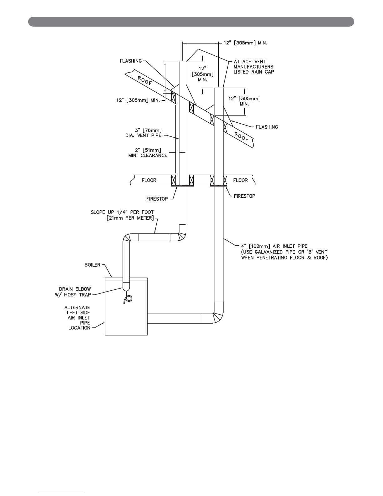
1. Vent pipe and air inlet terminations must be within the
maximum and minimum vent and air intake lengths
shown in Tables 4.1 and 4.2.
2. Vent pipe and air inlet pipe must terminate 12"
(305 mm) above expected snow lines. Vent pipe must
be a minimum 12" (305 mm) above and 12" (305
mm) horizontally from air inlet pipe. See Figure 4.3.
3. Attach a vent manufacturer's listed rain cap to both
the vent pipe and air inlet pipe.
4. Provide 2" (51 mm) clearance between vent pipe and
combustible construction. No clearance is required
between air inlet pipe and combustible construction.
5. See vertical venting section in vent manufacturer's
instructions for recommendations for penetration
through roof.
D . CONDENSATE TRAP INSTALLATION
Locate condensate hose and cable tie in Accessory Carton.
Connect hose to drain fitting on condensate elbow. Form a
3" diameter loop and secure with cable tie. Fill loop with
water. Pipe to drain or condensate receiver. See Figure 4.2.
E . VENT PIPE INSTALLATION
1. For minimum and maximum vent pipe lengths see
Table 4.1.
2. Use only 3" (76 mm) diameter Type AL29-4C
stainless steel vent pipe and fittings for venting of
flue gases from the boiler. When using other than
Heat-Fab vent pipe, an adapter must be installed
on the outlet of condensate elbow. See Figure 4.2.
Adapter part numbers are as follows:
3. Attach remaining pipe and fittings per each
manufacturer’s vent instructions. Use only the silicone
recommended by vent pipe manufacturers. Maintain
proper clearance to combustible construction – see
Section 1, Preinstallation.
4. Horizontal portions of the vent pipe shall slope upward
from the boiler towards the vent termination, not less than
1/4" per foot (21 mm per meter).
Parties horizontales de l'évent doit pente ascendante de
la chaudière vers la terminaison de ventilation, pas
moins de 1/4 "par pied (21 mm par mètre).
5. Support horizontal lengths of the vent system to
prevent sagging by use of metal strapping or
equivalent means. Locate supports at not more than
four (4) foot intervals.
Fournir un support à toute portion horizontale du
système d’évacuation à l’aide de courroies de metal
ou une méthode équivalente afin de l’empêcher de
s’affaisser. Placer les supports à des intervalles ne
dépassant pas cent vingt deux (122) centimètres (4
po), ou en suivant les recommandations d’ installation
du fabricant.
6. Vertical Venting Only – If there is no solid anchor
point in the system below the roof for supporting
vertical sections of the vent pipe (i.e. Firestop
Support, etc.), a special vent support system will be
required. See vent manufacturer's instructions for
additional information.
VENTING, VENTILATION AND AIR INLET
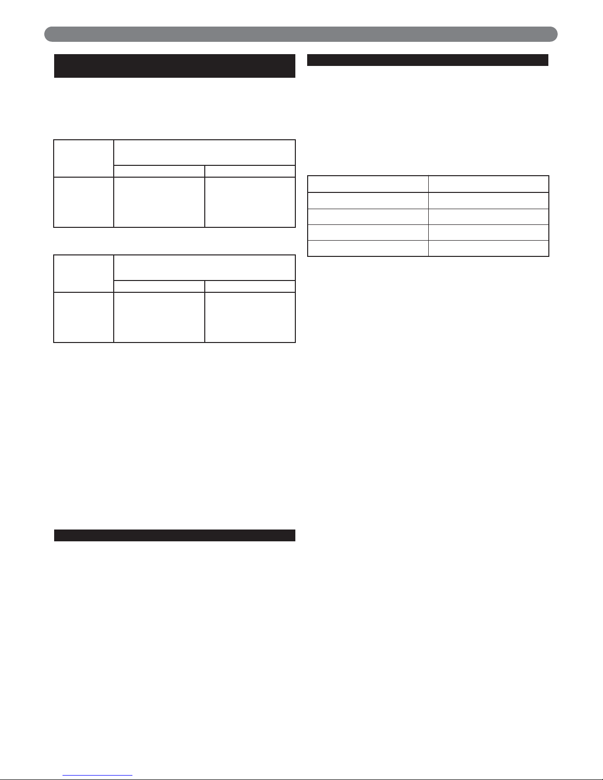
Table 4.1
Table 4.2
* Each 90° elbow equals 5 feet (1.5 meters) of equivalent length.
Boiler Model
*Equivalent Length of 4" (102 mm) Diameter
Aluminum/Galvanized Air Inlet Pipe
Minimum Length Maximum Length
PSCII-03
PSCII-04
PSCII-05
PSCII-06
12 feet (4.0 m)
12 feet (4.0 m)
12 feet (4.0 m)
12 feet (4.0 m)
70 feet (21.0 m)
70 feet (21.0 m)
63 feet (19.0 m)
63 feet (19.0 m)
Boiler Model
*Equivalent Length of 3" (76 mm) Diameter
Stainless Steel Vent Pipe
Minimum Vent Length Maximum Vent Length
PSCII-03
PSCII-04
PSCII-05
PSCII-06
8 feet (2.5 m)
8 feet (2.5 m)
8 feet (2.5 m)
8 feet (2.5 m)
52 feet (15.5 m)
52 feet (15.5 m)
45 feet (13.5 m)
45 feet (13.5 m)
11
Pipe Manufacturer Adapter
Flex-L Star-34 SRAPSCA3*
Heat-Fab Saf-T Vent Adapter not required
ProTech FasNSeal FSA-HFA3*
Z-Flex Z-Vent 2SVSSLA2*
* Available from Vent Pipe Manufacturer
Page 14
12
Figure 4.3: Vertical Venting System
VENTING, VENTILATION AND AIR INLET
Page 15

13
F. AIR INLET PIPE INSTALLATION
1. For maximum air inlet pipe lengths see Table 4.2.
2. Use only 4" (102 mm) diameter galvanized pipe or 4"
(102 mm) diameter flexible aluminum vent for
supplying combustion air to boiler inlet air box.
3. Boiler connection can be from either right or left side
of boiler jacket. Determine which jacket side air inlet
piping is to be routed and remove the 4-1/2" (114
mm) jacket knock-out.
4. Attach a 4" (102 mm) diameter 90 degree elbow to
top of air box and connect air inlet piping.
5. Support air inlet piping using the same methods and
requirements as shown in the previous section for vent
pipe support.
6. Seal all connections using silicone.
7. To prevent condensation from forming on exposed
portions of Wall Thimble and 4" (102 mm) diameter
air inlet piping, wrap exposed areas with insulation.
G. AIR FOR VENTILATION
1. Provide air openings for adequate ventilation to
prevent ambient boiler room temperature from
exceeding 120°F (49°C) during boiler operation. This
is to maintain all the boiler controls below maximum
service temperatures. Openings should be fixed in the
open position during operation.
H. BOILER REMOVAL FROM COMMON
VENTING SYSTEM
At the time of removal of an existing boiler, follow these
steps with each appliance remaining connected to the
common venting system placed in operation, while the
other appliances remaining connected to the common
venting system are not in operation:
Au moment de retirer une chaudière existante, il est
important de suivre les étapes suivantes pour chaque
appareil raccordé au système d’évacuation commun qui
sont en service, alors que les autres appareils demeurant
raccordés au système d’évacuation commun ne sont pas
en service :
a. Seal any unused openings in the common venting
system.
Sceller toute ouverture du système d’évacuation
commun non utilisée.
b. Visually inspect the venting system for proper size and
horizontal pitch and determine there is no blockage or
restriction, leakage, corrosion and other deficiencies
which could cause an unsafe condition.
Effectuer un contrôle visuel du système d’évacuation
pour vérifier la taille et la pente horizontale et
s’assurer qu’il n’existe aucun blocage ou obstruction,
fuite, corrosion ni tout autre problème pouvant
menacer la sécurité.
c. Insofar as is practical, close all building doors and
windows and all doors between the space in which
the appliances remaining connected to the common
venting system are located and other spaces of the
building. Turn on any clothes dryers and any
appliance not connected to common venting system.
Turn on any exhaust fans, such as range hoods and
bathroom exhausts, so they will operate at maximum
speed. Do not operate a summer exhaust fan. Close
fireplace dampers.
Dans la mesure du possible, fermer toutes les portes
et fenêtres de l’immeuble ainsi que toutes les portes
entre l’espace dans lequel les appareils qui demeurent
raccordés au système d’évacuation commun se
trouvent et le reste de l’immeuble. Mettre en marche
les sécheuses et tout autre appareil non raccordé au
système d’évacuation commun. Mettre en marche
tous les ventilateurs aspirant, tels que les hottes de
cuisinière et les ventilateurs de salle de bain, en les
faisant fonctionner à vitesse maximum. Ne pas faire
fonctionner les ventilateurs aspirant d’été. Fermer les
registres de foyers.
d. Place in operation the appliance being inspected.
Follow the lighting instructions. Adjust thermostat so
appliance will operate continuously.
Mettre en service l’appareil à inspecter. Suivre les
instructions concernant l’allumage. Régler le
thermostat afin que l’appareil fonctionne sans arrêt.
e. Test for spillage at the draft hood relief opening after 5
minutes of main burner operation. Use the flame of a
match or candle, or smoke from a cigarette, cigar, or
pipe.
Vérifier toute fuite à l’orifice de décharge du coupetirage après que le brûleur ait fonctionné pendant 5
minutes. Utiliser la flamme d’une allumette ou d’une
chandelle ou encore la fumée d’une cigarette, d’un
cigare ou d’une pipe.
f. After it has been determined that each appliance
remaining connected to the common venting system
properly vents when tested as outlined above, return
doors, windows, exhaust fans, fireplace dampers and
any other gas-burning appliance to their previous
conditions of use.
Après avoir établi que les résidus de combustion de
chaque appareil qui demeure raccordé au système
commun sont adéquatement évacués lorsque soumis
au test décrit ci-dessus, remettre en place les portes,
fenêtres, portes intérieures, ventilateurs aspirants,
registres de foyer et appareils fonctionnant au gaz.
VENTING, VENTILATION AND AIR INLET
Page 16

14
VENTING, VENTILATION AND AIR INLET
g. Any improper operation of the common venting
system should be corrected so that the installation
conforms with the current edition of the National Fuel
Gas Code, ANSI Z223.1/NFPA 54 and/or CAN/CSA
B149.1, Natural Gas and Propane Installation Code.
When resizing any portion of the common venting
system, the common venting system should be resized
to approach the minimum size as determined using
the appropriate tables in the National Fuel Gas Code,
ANSI Z223.1/NFPA 54 and/or CAN/CSA B149.1,
Natural Gas and Propane Installation Code.
Tout fonctionnement inadéquat du système
d’évacuation commun doit être corrigé de manière à
respecter les normes du National Fuel Gas Code,
ANSI Z223.1/NFPA 54 et/ou des Codes d’installation
CAN/ACG B149. Lorsqu’il est nécessaire de modifier
les dimensions de toute portion du système
d’évacuation commun, ces dernières doivent être
modifiées de manière à respecter les dimensions
minimums indiquées dans les tableaux du chapitre «
Sizing of Category I Venting Systems » du National
Fuel Gas Code, ANSI Z223.1/NFPA 54 ou des Codes
d’installation CAN/ACG B149
Page 17
15
1. Size and install the gas supply piping properly in order
to provide a supply of gas sufficient to meet the
maximum demand without undue loss of pressure
between the meter and the boiler.
2. Determine the volume of gas to be provided to the
boiler in cubic feet per hour. To obtain this value,
divide the Btu per hour rating (on the boiler rating
plate) by the heating value of the gas in Btu per cubic
feet. Obtain the heating value of the gas from the gas
supplier. As an alternative, use Table 5.1 on the next
page to obtain the volume of gas to be provided to
the boiler.
3. Use the value obtained above as the basis for piping
sizing. Size the gas piping in accordance with Table
5.2. Consult the National Fuel Gas Code, ANSI
Z223.1/NFPA 54 and/or CAN/CSA B149.1, Natural
Gas and Propane Installation Code.
4. Locate the drop pipe adjacent to, but not in front of
the boiler.
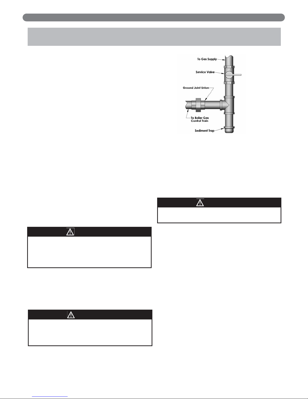
5. Install a sediment trap. See Figure 5.1. Locate a tee in
the drop pipe at same elevation as the gas inlet
connection to the boiler. Extend the drop pipe to a
pipe cap.
6. Install a ground joint union ahead of the gas control
assembly to permit servicing of the control. Some
local codes require an additional service valve when
using the combination gas controls. If your code
requires such a valve, a suggested location is shown in
Figure 5.1.
7. Check piping for leaks prior to placing the boiler in
operation.
Use an approved gas detector, a non-corrosive leak
detection fluid or other leak detection method. If leaks
are found, turn off all gas flow and repair as
necessary.
8. Disconnect the boiler and its individual shut-off valve
from the gas supply piping system during any pressure
testing of that system at test pressure in excess of 1/2
psig (3.5 kPa).
Isolate the boiler from the gas supply piping system by
closing its individual service valve during any pressure
testing of the gas supply piping system at test pressure
equal to or less than 1/2 psig (3.5 kPa).
9. Minimum permissible supply pressure for purposes of
input adjustment (Inches Water Column):
Natural Gas 5.0" (1.2 kPa)
LP Gas 11.0" (2.7 kPa)
Maximum permissible supply pressure to the boiler
(Inches Water Column):
Natural Gas 13.5" (3.4 kPa)
LP Gas 13.5" (3.4 kPa)
GAS PIPING
5. GAS PIPING
Figure 5.1: Gas Connection to Boiler
When checking for leaks, do not use matches,
candles, open flames or other methods that provide a
source of ignition. This can ignite a gas leak,
resulting in fire or explosion.
WARNING
Use a pipe joint sealing compound that is resistant to
the action of liquefied petroleum gas. A non-resistant
compound may lose sealing ability in the presence of
this gas, resulting in a gas leak and fire or explosion
potential.
WARNING
Do not subject the gas valve to more than 1/2 psi
(3.5 kPa) pressure. Doing so may damage the valve.
CAUTION
Page 18
16
GAS PIPING
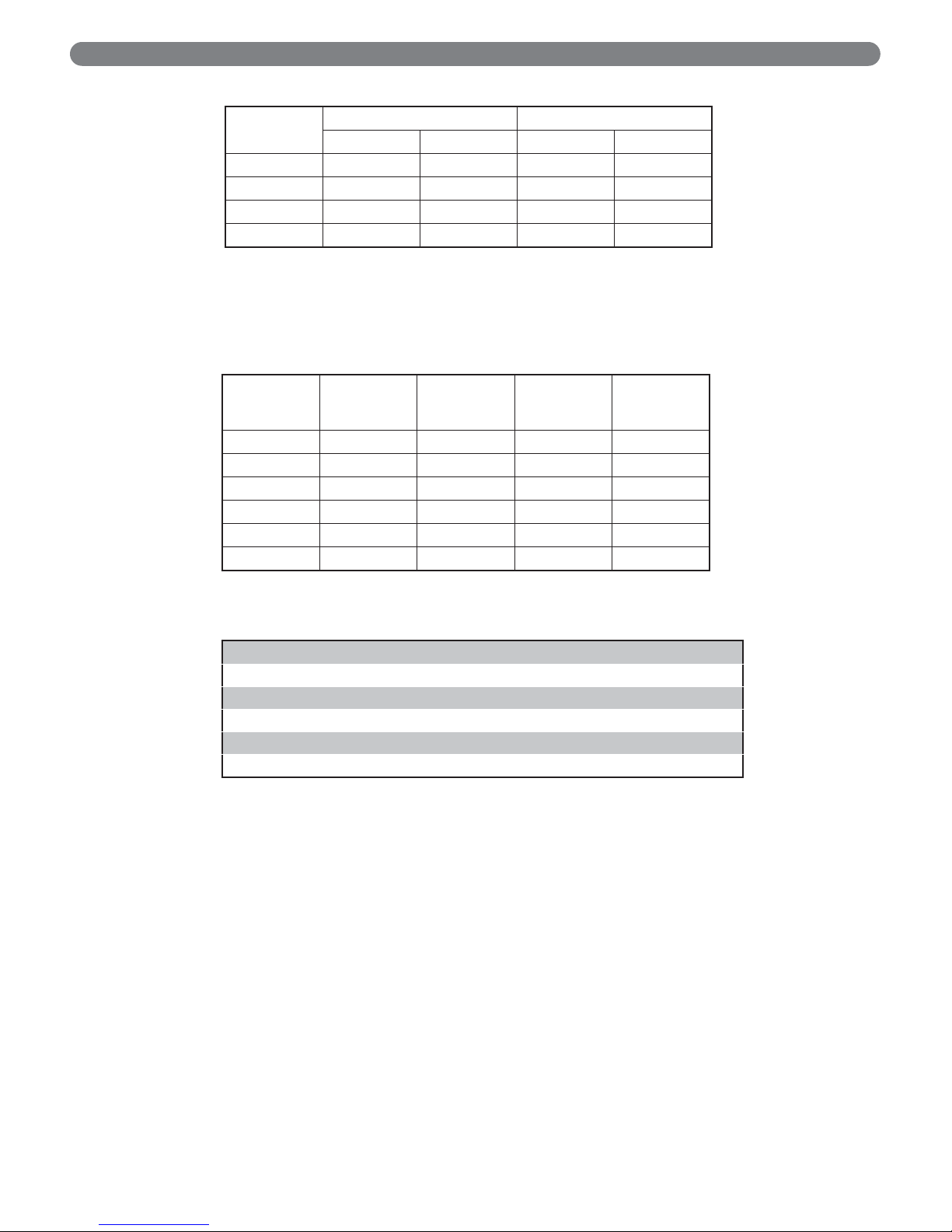
Table 5.2: Pipe Capacity
Capacity of pipe of different diameters and lengths in cubic feet per hour (cubic meter per
hour) with pressure drop of 0.3 inches of water (75 Pa) and specific gravity of 0.60. No
allowance for an ordinary number of fittings is required.
Table 5.1: Natural Gas
Pipe
Length in
Feet (Meters)
3/4"
Pipe
1"
Pipe
1-1/4"
Pipe
1-1/2"
Pipe
10 (3.0) 278 (7.9) 520 (14.7) 1050 (29.7) 1600 (45.3)
20 (6.1) 190 (5.4) 350 (9.9) 730 (20.7) 1100 (31.1)
30 (9.1) 152 (4.3) 285 (8.1) 590 (16.7) 890 (25.2)
40 (12.2) 130 (3.7) 245 (6.9) 500 (14.2) 760 (21.5)
50 (15.2) 115 (3.3) 215 (6.1) 440 (12.5) 670 (19.0)
60 (18.3) 105 (3.0) 195 (5.5) 400 (11.3) 610 (17.3)
Boiler
Model
Natural Gas Input LP Gas Input
Cu. Ft/hr Cu. Meter/hr Cu. Ft/hr Cu. Meter/hr
PSCII-03 65 1.8 26 0.7
PSCII-04 90 2.5 36 1.0
PSCII-05 120 3.4 48 1.4
PSCII-06 150 4.2 60 1.7
Specific Gravity 0.50 0.55 0.60 0.65 0.70 0.75
Correction Factor 1.10 1.04 1.00 0.96 0.93 0.90
Specific Gravity 0.80 0.85 0.90 1.00 1.10 1.20
Correction Factor 0.87 0.84 0.82 0.78 0.74 0.71
Specific Gravity 1.30 1.40 1.50 1.60 1.70 1.80
Correction Factor 0.68 0.66 0.63 0.61 0.59 0.58
Maximum Capacity Correction Factors for Specific Gravity
other than 0.60.
Page 19
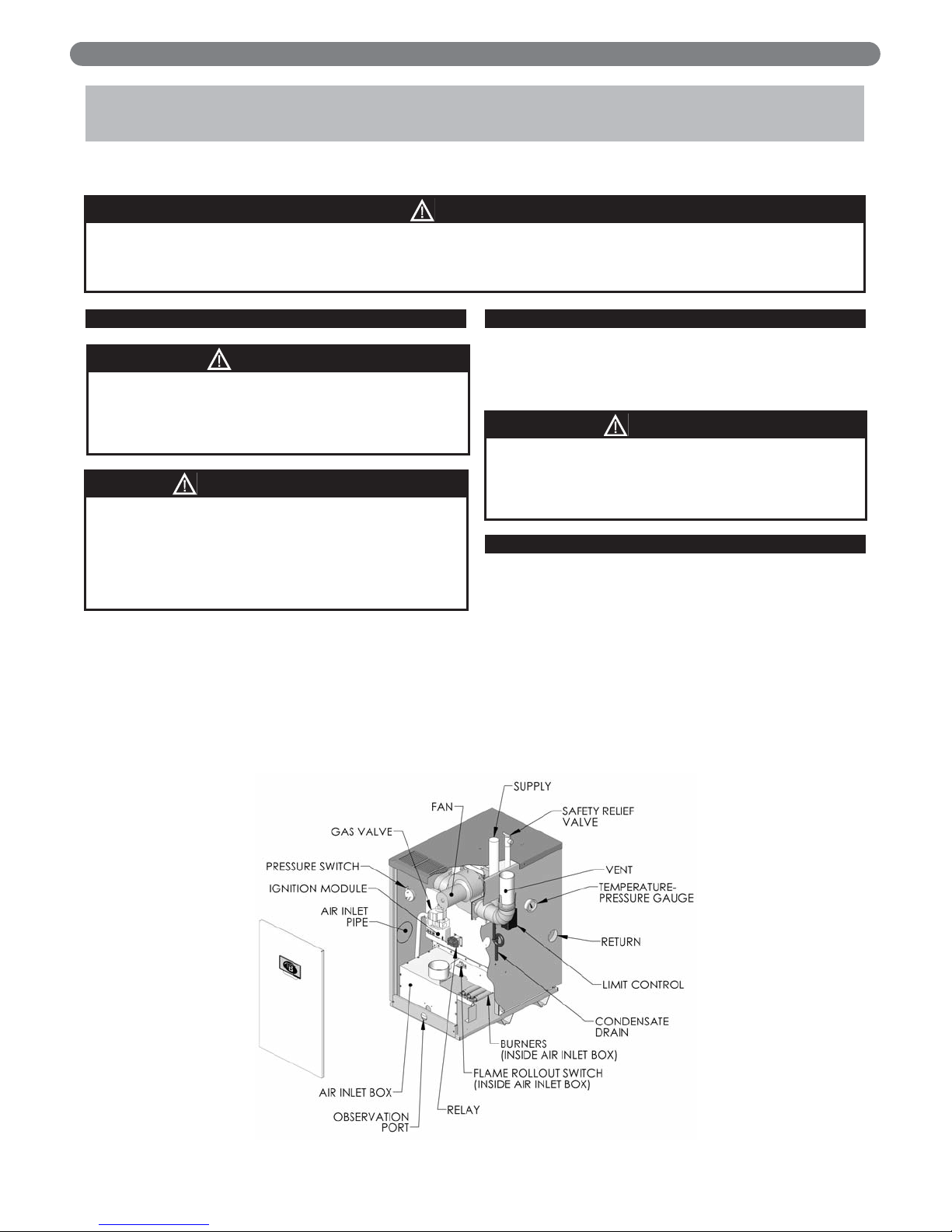
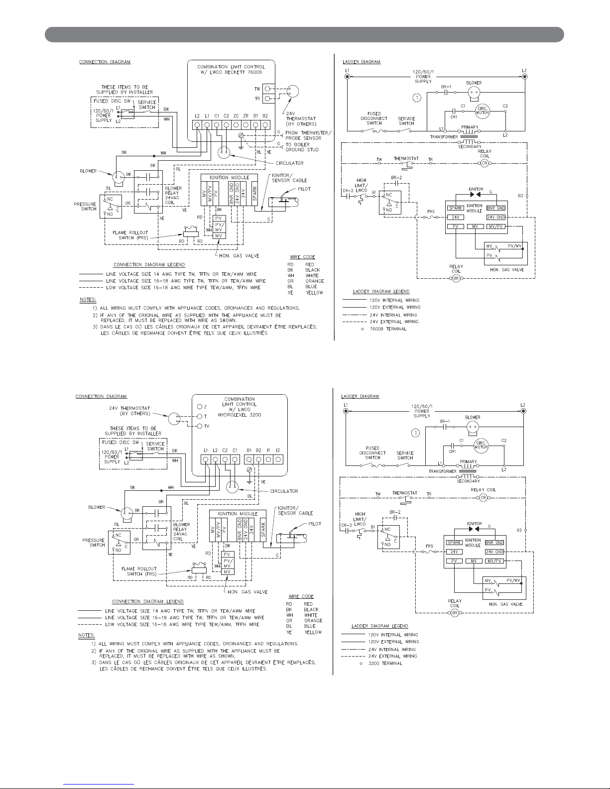
A. WIRING
1. See Figure 6.1 for location of wiring and controls. Use
Figure 6.2 to connect the boiler to a power supply
and to connect components to the boiler.
2. Connect the boiler by a separate, permanently live
electrical supply line with a fused switch.
3. Adjust the thermostat heat anticipator to 0.2 Amp.
B. ZONED SYSTEM WIRING
See Figure 6.4 for typical wiring with zone valves. See
Figure 6.5 for typical wiring with zone circulators. When
wiring a zoned heating system, follow all applicable
codes, ordinances and regulations.
C. CONTROLS
1. For proper location of controls and accessories refer to
Figure 6.1.
2. See the attached control sheets for specific details
regarding the installation of the various controls.
3. This boiler is supplied with safety devices in addition
to the limit. For a description of these devices and
how they work to ensure the safe operation of the
boiler, see Section 7.
4. If the circulator is mounted in the supply piping,
provide longer wiring harness as required.
ELECTRICAL
6. ELECTRICAL
This unit when installed must be electrically grounded in accordance with the requirements of the authority
having jurisdiction or, in the absence of such requirements, with the current edition of the
National Electrical
Code,
ANSI/NFPA 70 and/or the
Canadian Electrical Code
, Part 1, CSA C221.
NOTICE
Figure 6.1: Wiring, Controls and Safety Devices
Install all electrical wiring in accordance with the National Electrical Code and local requirements.
Do not power zone valves directly from the boiler
transformer. Doing so will greatly reduce the life of
the transformer. Use a separate transformer sized to
handle the total of all zone valve electrical loads.
NOTICE
Label all wires prior to disconnection when servicing
controls. Wiring errors can cause improper and
dangerous operation. Verify proper operation after
servicing.
CAUTION
Identifier tous les câbles avant de les débrancher au
moment d’effectuer l’entretien des commandes. Des
erreurs dans le raccordement des câbles
d’alimentation peuvent causer un fonctionnement
inadéquat et dangereux. Vérifier le bon
fonctionnement après les travaux d’entretien.
AVERTISSEMENT
17
Page 20
18
ELECTRICAL
Figure 6.2: Wiring Diagram, Spark Ignited Pilot, Becket 7600 Limit Control
Figure 6.3: Wiring Diagram, Spark Ignited Pilot, Hydrolevel 3200 Limit control
Page 21

19
ELECTRICAL
D. BOILER SEQUENCE OF OPERATION
1. Thermostat calls for heat.
2. Limit control energizes circulator.
3. Limit control energizes B1 circuit if boiler water
temperature is below setpoint minus differential.
Setpoint is calculated according to thermostat cycle
and economy/efficiency setting. See limit control
literature for further information.
4. BR relay energizes blower.
5. Negative pressure induced by blower switches
Pressure Switch, continuing power through closed
contacts (BR-2) and flame roll-out switch.
6. Gas valve energizes.
a. Ignitor on.
b. Pilot gas on, igniting pilot
7. Pilot flame detected.
a. Ignitor off.
b. Main gas on, igniting main burners.
Note: If pilot flame is not detected within 90 seconds,
the igniter and pilot are turned off for 5 minutes. The
sequence then resumes at Step 6a.
8. Call for heat ends.
a. Pilot and main gas off, extinguishing pilot and
main burners.
b. Blower and circulator off.
Page 22

20
A. COMPLETING THE INSTALLATION
1. Confirm that all water, gas and electricity are
turned off.
2. Inspect the boiler combustion chamber for foreign
objects and remove if present.
3. Check physical condition of burners and pilot. Make
certain that there are no unusual bends or
perforations in the burners or pilot. Replace
components if necessary.
4. Verify that water piping, venting, gas piping and
electrical wiring and components are installed
properly. Refer back to previous sections of these
instructions as well as equipment manufacturer’s
instructions as necessary.
5. Fill the boiler and system with water, making certain
to vent all air from all points in the system. To check
water level in the system, open and close each vent in
the system. Water should exit from each vent when it
is opened.
6. The pressure reducing valve on the fill line will
typically allow the system to be filled and pressurized
to 12 psi (83 kPa). Consult the valve and expansion
tank manufacturer for more specific information.
7. Check joints and fittings throughout the system for
leaks. If leaks are found, drain the system and repair
as required.
8. Connect a manometer to the 1/8" NPT inlet pressure
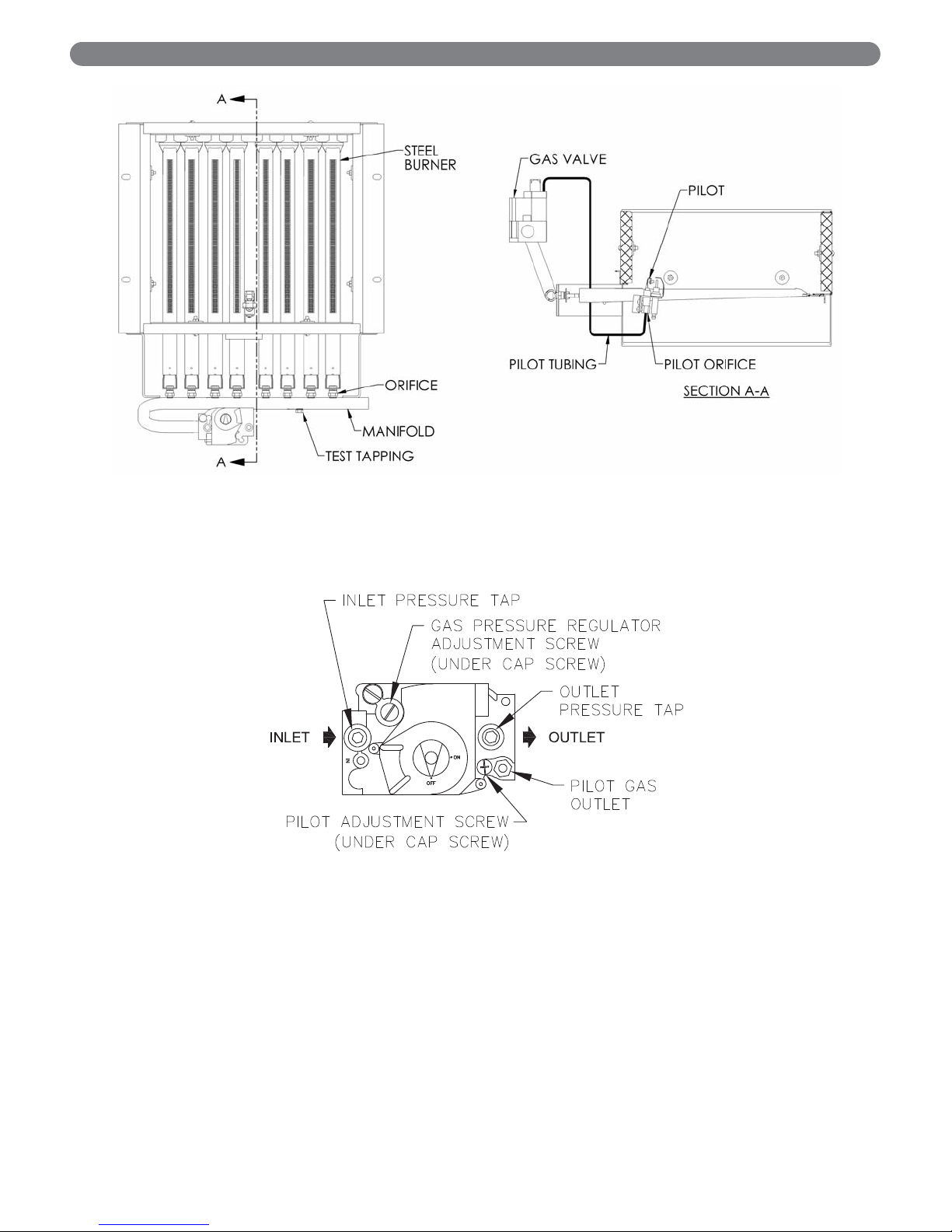
tap on the gas valve. See Figure 7.2.
9. Confirm that the gas supply pressure to the boiler is
above the minimum and below the maximum values
for the gas being used. See the end of Section 5 for
these values. If a supply pressure check is required,
isolate the boiler and gas valve before performing the
pressure check. If the supply pressure is too high or
too low, contact the gas supplier.
10. Turn on electricity and gas to boiler.
11. Light the boiler by following the Lighting/Operating
Instructions label mounted to the jacket panel. The
initial ignition may require several tries as the piping is
purged of air.
12. Use the sequence description and Figure 6.3 in
Section 6 (Electrical) to follow light-off and shutdown
sequences and to assist in diagnosing problems. If the
boiler does not function properly, consult Section 8,
Troubleshooting.
7. START-UP PROCEDURES
START-UP PROCEDURES
Page 23
21
START-UP PROCEDURES
Figure 7.1: Gas Valve, Manifold and Burner Assembly – Intermittent Ignition
Figure 7.2: Valve Tapping and Adjustment Screw Locations
Page 24
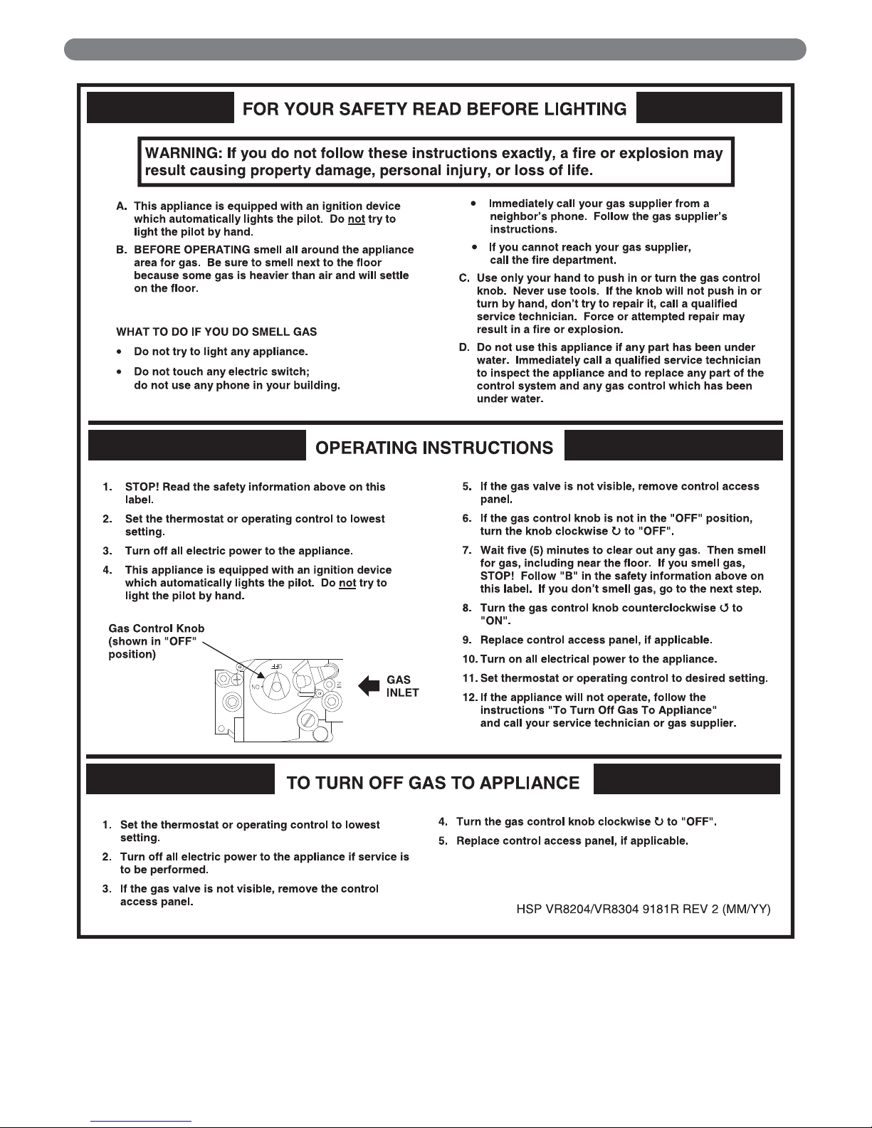
22
START-UP PROCEDURES
Figure 7.3: Operating Instructions
Page 25
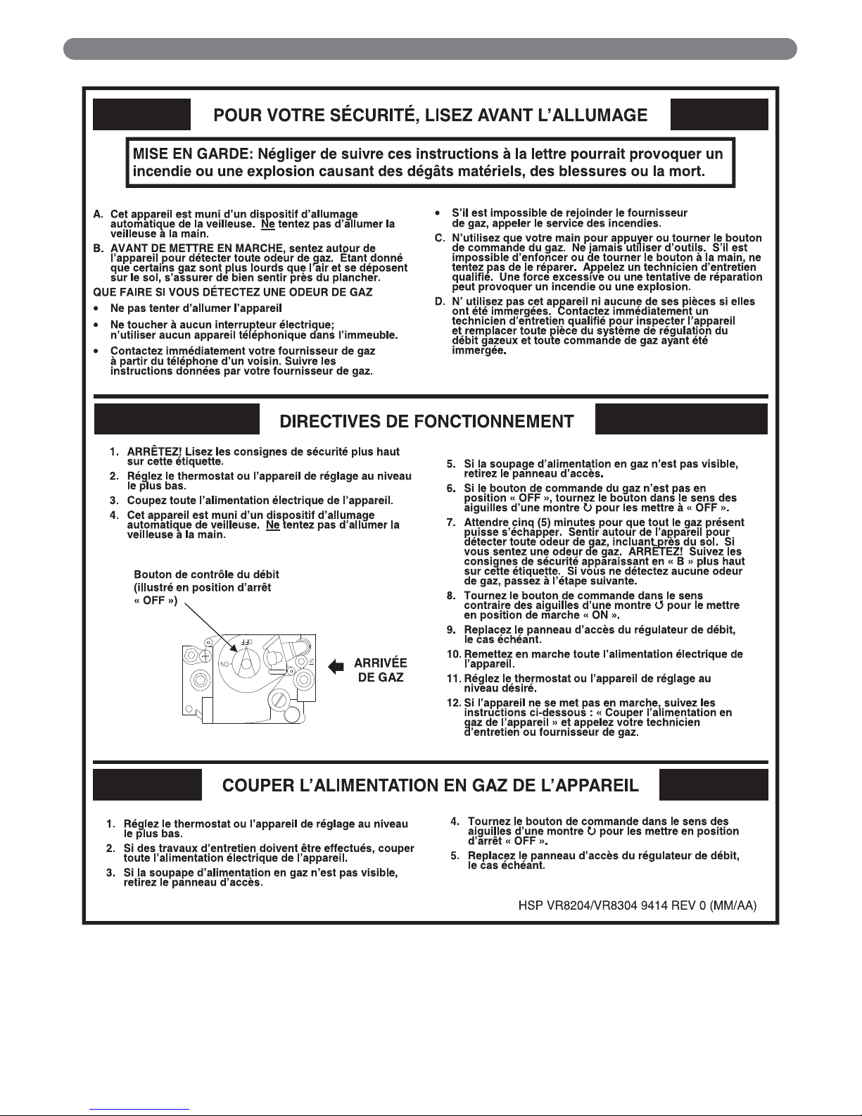
23
START-UP PROCEDURES
Figure 7.4: Operating Instructions
Page 26

24
START-UP PROCEDURES
B. CONTROL DESCRIPTIONS
See Figure 6.1 in Section 6 (Electrical) for locations of
these devices.
1. FLAME ROLL-OUT SAFETY SHUT-OFF SWITCH
(FLAME ROLL-OUT SWITCH) – A thermally
activated switch located between the first burner from
the left and the manifold bracket. The flame roll-out
safety shut-off switch will sense excessive temperature
caused by continued flame roll-out and shut down
main burner gas. This is a non-recycling switch that
must be replaced once it has been activated and the
cause of the roll-out eliminated.
2. DIFFERENTIAL PRESSURE SWITCH – This device
senses a negative or suction pressure in the blower
housing and air box when the blower is energized. If
there is not excessive blockage in the venting system
or air inlet vent the switch will close, allowing power
to energize the ignition system.
3. LIMIT WITH LOW WATER CUT-OFF– A Beckett
7600B or Hydrolevel 3200 control incorporate a
thermally activated adjustable switch that will shut
down main burner gas if the supply water temperature
exceeds the control setting It will also shut down main
burner gas if the water level in the boiler drops below
the control’s sensing well. The temperature switch will
automatically reset when the boiler supply water
temperature drops below the control setpoint. The low
water cut-off switch will automatically reset when the
water level is above the control’s sensing well.
4. LOW WATER CUT-OFF (FOR GRAVITY SYSTEMS
OR HOT WATER BOILERS INSTALLED ABOVE
RADIATION LEVEL) – A level-sensing device (float or
probe) located in supply piping near the boiler. If
water level in the system drops below the control’s
position, it will shut down main burner gas. The
control will automatically reset once the water level
rises above its position.
C. ADJUSTMENT OF GAS PRESSURE
REGULATOR
1. Move the manometer to either the outlet pressure tap
on the gas valve or to the burner manifold test tap.
Set manifold pressure as follows for various gases.
a. Natural Gas . . .3.5" Water Column (0.9 kPa)
b. LP Gas . . . . . .10.0" Water Column (2.5 kPa)
2. To adjust gas pressure, turn adjusting screw of gas
pressure regulator counterclockwise to decrease
pressure, clockwise to increase pressure. Refer to
Figure 7.2 for location of gas pressure regulator.
Replace the cap screw when adjustment is complete.
3. In no case should the final manifold pressure vary
more than ±0.3 inches water column (0.07 kPa) from
the above specified pressures. Any necessary major
changes in the flow should be made by changing the
size of the burner orifice spuds.
4. When adjustment is complete, turn off boiler, gas flow
and electricity to boiler. Remove manometer and plug
tapping with plug provided. Turn utilities back on and
resume checkout.
D. CHECKING BURNER INPUT
1. Refer to rating label mounted on the jacket top panel
to obtain the rated BTU per hour input. In no case
shall the input to the boiler exceed the value shown
on the rating label.
2. Check input by use of the following formula
(PB Heat suggests reading meter for 2 Cu.Ft. [0.0566
cubic meter]):
U.S. Customary Units:
Input (BTU/Hr.)= 3600 x F x H
T
Where:
3600 – Seconds per hour
F – Cubic Feet of Gas Registered on Meter
H – Heat Value of Gas in BTU/Cubic Feet
T – Time in Seconds the Meter is Read
SI Metric Units
Input (kW)= 3600 x F x H
T x 3.6
Where:
3600 – Seconds per hour
3.6 – Megajoule (MJ) per kilowatt hour (kWhr)
F – Cubic Meters of Gas Registered on Meter
H – Heating Value of Gas in MJ/Cubic Meter
T – Time in Seconds the Meter is Read
3. As an alternative, use Table 7.1a and 7.1b. Use the
heating value provided by gas supplier. Use a
stopwatch to record the time it takes for 2 cubic feet
(0.0566 cubic meter) of gas to pass through the meter.
Read across and down to determine rate.
E. CHECK-OUT PROCEDURE
1. After starting the boiler, be certain all controls are
working properly. Check to be sure that the limit will
shut off the boiler in the event of excessive water
temperature. This can be done by lowering the limit
setting until the main burners shut down. When
proper limit function is confirmed, return the dial to its
previous setting.
2. To check operation of the ignition system safety
shut-off features:
a. Turn gas supply off.
b. Set thermostat or controller above room
temperature to call for heat. Watch for igniter
spark at pilot burner.
c. Igniter will continue to spark for 90 seconds.
It will then de-energize for 5 minutes before
restarting the sequence.
d. Turn gas supply on.
e. Reset the boiler and control by following
Operating Instructions.
f. Observe boiler operation through one complete
cycle.
Page 27
25
3. Low Water Cut-Off (if used) – Consult the
manufacturer’s instructions for the low water cut-off
operational check procedure.
4. Check the system to make sure there are no leaks or
overfilling problems which might cause excessive
make-up water to be added. Make-up water causes
liming in the boiler and brings in oxygen. Oxygen can
cause severe damage to the boiler though oxygen
corrosion pitting.
5. Check the expansion tank and automatic fill valve (if
used) to confirm that they are operating correctly. If
either of these components causes high pressure in the
system, the boiler relief valve will weep or open,
allowing fresh water to enter the system.
6. Do not allow the system controls to subject the boiler
to excessively low water temperatures, which would
cause condensation of flue gases and corrosion of the
boiler. Operate the boiler at a temperature above
130°F (54°C). Adjust the boiler limit as required to
maintain boiler temperature above this level.
7. Check the general condition of the system including
piping support, joints, etc. Check cleanliness of the
radiators, baseboard units and/or convectors. Clean
them to the extent possible. If radiators do not heat
evenly, vent any remaining air from them.
8. Review operation and User’s Information Manual with
end-user.
9. Complete the Warranty Card and submit it to PB
Heat, LLC.
10. Hang the Installation, Operation and Maintenance
Manual, User’s Information Manual, and Vent
Manufacturer’s Information Manual in an accessible
position near the boiler.
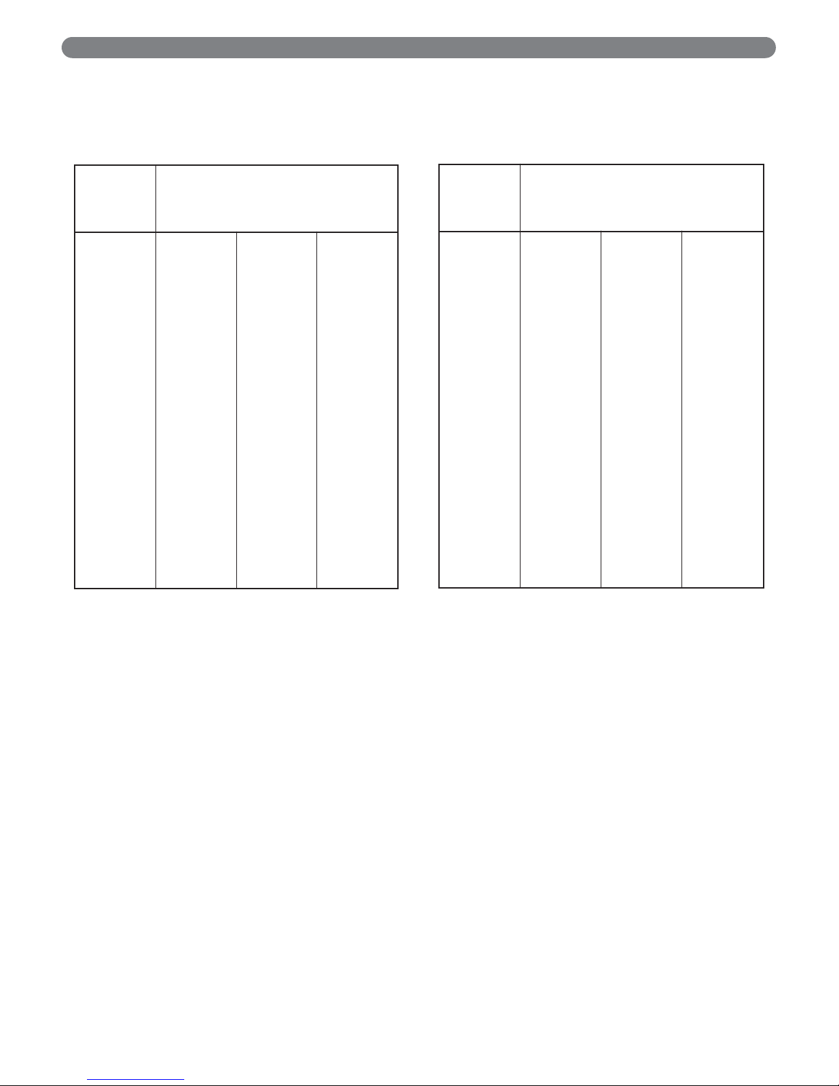
Table 7.1a: Meter Conversion Natural Gas
(U.S. Customary Units)
Table 7.1b: Meter Conversion Natural Gas
(SI Metric System)
Burner inputs in kW for various meter timings and
heating values. (Tables based on 0.0566 cubic meters
of gas through the meter).
Burner inputs in Btu/hr for various meter timings and
heating values. (Tables based on 2 cubic feet of gas
through the meter).
Time that
meter is
read (sec)
Heat Value of Gas
(MJ/cubic meter)
37.26 38.19 39.12
25
30
35
40
45
50
55
60
65
70
75
80
85
90
95
100
105
110
115
120
125
84.36
70.30
60.25
52.72
46.86
42.18
38.34
35.15
32.44
30.13
28.12
26.36
24.81
23.43
22.20
21.09
20.08
19.17
18.34
17.57
16.87
86.46
72.05
61.76
54.04
48.03
43.23
39.30
36.03
33.25
30.88
28.82
27.02
25.43
24.02
22.75
21.62
20.59
19.65
18.80
18.01
17.29
88.57
73.81
63.26
55.35
49.20
44.28
40.26
36.90
34.06
31.63
29.52
27.68
26.05
24.60
23.31
22.14
21.09
20.13
19.25
18.45
17.71
Time that
meter is
read (sec)
Heat Value of Gas
(Btu/cubic foot)
1000 1025 1050
25
30
35
40
45
50
55
60
65
70
75
80
85
90
95
100
105
110
115
120
125
288000
240000
205714
180000
160000
144000
130909
120000
110769
102857
96000
90000
84706
80000
75789
72000
68571
65455
62609
60000
57600
295200
246000
210857
184500
164000
147600
134182
123000
113538
105429
98400
92250
86824
82000
77684
73800
70286
67091
64174
61500
59040
302400
252000
216000
189000
168000
151200
137455
126000
116308
108000
100800
94500
88941
84000
79579
75600
72000
68727
65739
63000
60480
START-UP PROCEDURES
Page 28
26
TROUBLESHOOTING
A. SHUT-DOWN CAUSED BY PILOT
OUTAGE, PRESSURE SWITCH OR
FLAME ROLL-OUT SAFETY
SHUT-OFF SWITCH
In the event of a shut-down caused by a pilot outage,
action of the pressure switch or flame roll-out safety shutoff switch effecting a shut-down of the main burners:
a. Refer to the Lighting/Operating Instructions in Figure
7.3 to properly turn off the gas to the boiler.
b. Turn off all electric power to the boiler.
c. Call a qualified heating service organization or local
gas company and have the cause of the shut-down
investigated and corrected.
d. Refer to Operating Instructions to re-start boiler.
B. TROUBLESHOOTING GUIDES
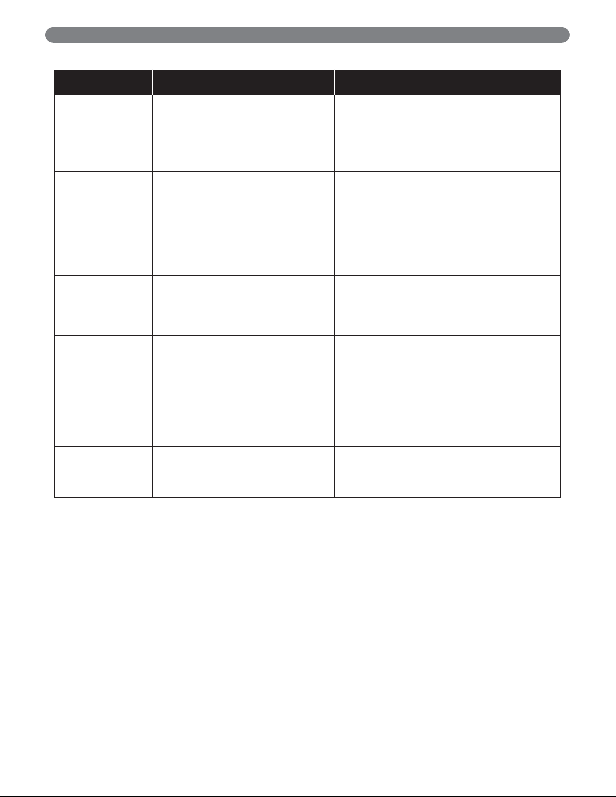
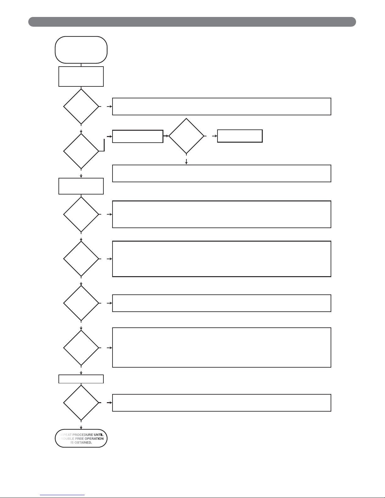
Use Table 8.1 and Figure 8.2 to assist in determining
causes and providing corrective actions to boiler
problems. These guides must be used only by qualified
service technicians. These individuals must follow all
applicable codes and regulations in repair of any boiler
problems.
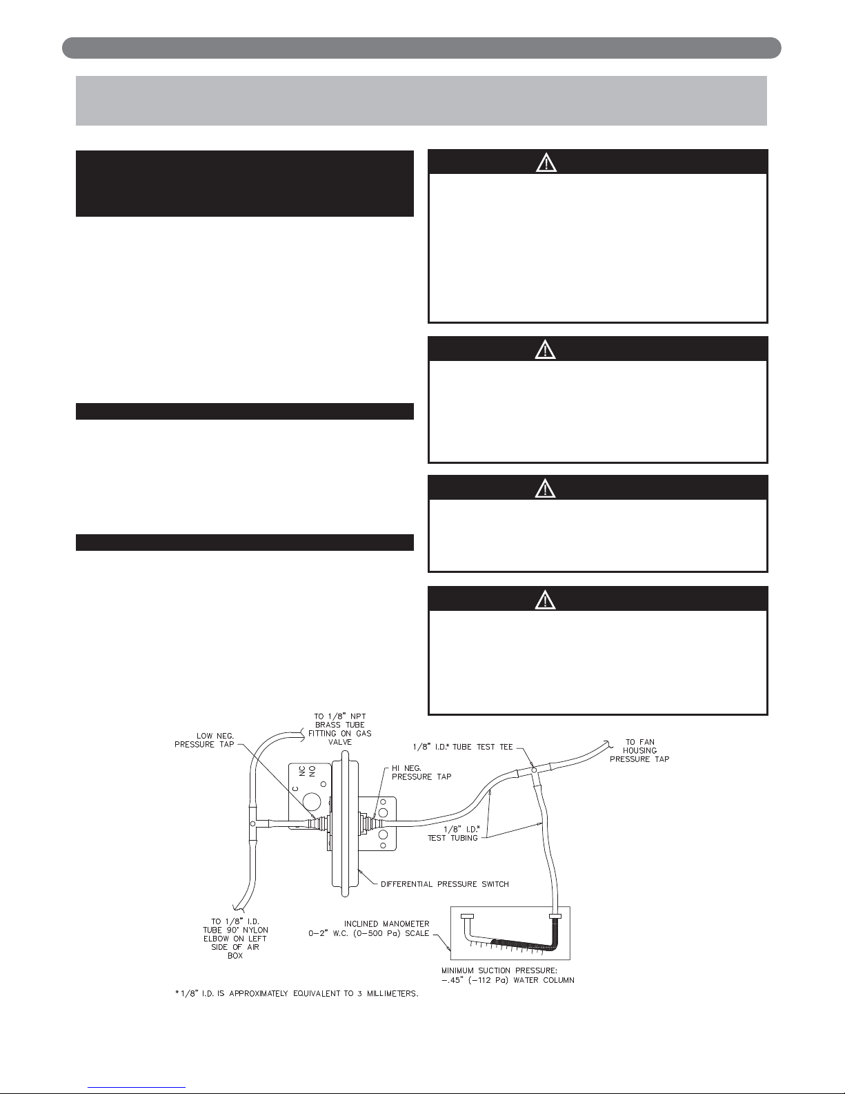
C. MEASURING SUCTION PRESSURE
Pressure switch requires minimum -0.45" W.C. (-112 Pa)
fan suction pressure to energize control circuit. Measure
when boiler has been operating at least 15 minutes. See
Figure 8.1.
8. TROUBLESHOOTING
Do not use this appliance if any part has been under
water. Improper or dangerous operation may result.
Immediately call a qualified service technician to
inspect the boiler and to replace any part of the
control system and any gas control which has been
under water.
WARNING
Label all wires prior to disconnection when servicing
controls. Wiring errors can cause improper and
dangerous operation. Verify proper operation after
servicing.
CAUTION
When servicing or replacing items that communicate
with the boiler water, be certain that:
●
There is no pressure on the boiler.
●
The boiler is not hot.
●
The power is off.
When servicing the gas valve or pilot, be certain that:
●
The gas is off.
●
The electricity is off.
DANGER
Figure 8.1: Measuring Fan Suction Pressure
Should overheating occur or the gas supply fail to
shut off, do not turn off or disconnect the electrical
supply to the pump. This may aggravate the problem
and increase the likelihood of boiler damage. Instead,
shut off the gas supply at a location external to the
appliance.
CAUTION
*
Page 29
27
TROUBLESHOOTING
Table 8.1: Boiler Troubleshooting Guide (Burners Functioning)
Problem Possible Causes Corrective Actions
Burners not functioning,
blower running.
1. Flame rollout switch open.
2. Pressure switch in closed position.
3. Ignition system problem.
1. Replace switch. Locate cause and correct.
2a. Check for plugged or damaged switch tubing.
2b. See Section “Measuring Suction Pressure” in boiler manual.
If adequate, replace pressure switch. If inadequate, check
for blockage or leak in vent system. If ok, replace blower.
3a. See ignition system troubleshooting guide below.
3b. See ignition system manufacturer literature for instructions
including key to control LED lamp diagnostics.
Burners not functioning,
blower not running.
1. No power.
2. Water Temperature below calculated setpoint
minus differential.
3. Limit Control not working.
1. Check line voltage wiring and fuses.
2a. Wait for calculated setpoint to rise / boiler temperature
to fall.
2b. Adjust efficiency/economy setting. See limit control
manufacturer’s literature.
3. Check wiring and contacts, relay, temperature setting.
Clean and adjust as necessary.
Burners will not shut
down.
1. Defective gas valve.
2. Short circuit.
1. See ignition system troubleshooting guide below
to troubleshoot gas valve. Replace if necessary.
2. Check and correct wiring.
Flashback or burning at
orifice spuds.
1. Manifold gas pressure too low.
2. Improperly sized/drilled orifice spuds.
3. Leaking gas valve.
4. Burrs on orifice.
5. Low supply gas pressure.
6. Draft problems in boiler room.
1. Adjust to proper pressure.
2. Install correct spuds.
3. Replace valve.
4. Remove burrs.
5. Contact gas supplier if natural gas.
6. Check air supply, ventilation and venting system.
Delayed ignition. 1. Insufficient pilot flame.
2. Pilot burner/orifice clogged.
3. Overfiring.
4. Misaligned burners or pilot.
5. Draft problem in boiler room.
1. Increase pilot gas flow.
2. Clean pilot burner and orifice.
3. Reduce rate to input on rating label.
4. Realign burners or pilot.
5. Check air supply, ventilation and venting system.
Boiler not heating
properly.
1. Underfiring.
2. Limit set too low.
3. Air in system.
4. Circulator malfunctioning.
5. Circulation system clogged.
6. Incorrect thermostat heat anticipator setting.
1. Increase rate to input on rating label.
2. Reset Aquastat to higher setting.
3. Vent air from all points in system.
4. Check circulator, replace if necessary.
5. Shut down and cool boiler, drain and flush system.
6. Adjust heat anticipator.
Fumes or gas odors. 1. Leaks in gas piping or fittings.
2. Leaks in gas service line or meter.
3. Obstructed flueways or vent.
4. Draft problem in boiler room.
5. Overfiring.
1. Locate and repair or replace.
2. Shut down boiler and notify gas provider.
3. Clean flueways or vent and remove obstructions.
4. Check air supply, ventilation and venting system.
5. Reduce rate to input on rating label.
Page 30
28
TROUBLESHOOTING
Figure 8.2: Intermittent Ignition System Troubleshooting Sequence
STAR T
BEFORE TROUBLESHOOTING,
FAMILIARIZE YOURSELF WITH
THE STARTUP AND
CHECKOUT PROCEDURES.
TURN GAS SUPPLY OFF,
TURN THERMOSTAT
(CONTROLLER) TO
“CALL FOR HEAT.”
NOTE: “CALL FOR HEAT” 24 VAC SUPPLY IS CONNECTED TO THE 24 V TERMINAL ON THE CONTROL.
POWER TO
MODULE? (24 V
NOMINAL)
YES
SPARK
ACROSS
IGNITER/
SENSOR
GAP?
YES
TURN GAS SUPPLY
ON AND RECYCLE
“CALL FOR HEAT.”
PILOT BURNER
LIGHTS?
YES
SPARK
STOPS WHEN
PILOT IS
LIT?
YES
CHECK LINE VOLTAGE POWER, LOW VOLTAGE TRANSFORMER, LIMIT CONTROLLER, THERMOSTAT (CONTROLLER), AND WIRING ALSO.
NO
CHECK AIR PROVING SWITCH ON COMBUSTION AIR BLOWER SYSTEM (IF USED) AND THAT THE VENT DAMPER END SWITCH (IF USED)
IS MADE.
PULL IGNITION LEAD AND
NO
CHECK SPARK AT MODULE.
CHECK IGNITION CABLE, GROUND WIRING, CERAMIC INSULATOR, AND SPARK GAP ARE CORRECT.
CHECK BOOT OF THE IGNITION CABLE FOR SIGNS OF MELTING OR BUCKLING, TAKE PROTECTIVE ACTION TO SHIELD CABLE
AND BOOT FROM EXCESSIVE TEMPERATURES.
CHECK THAT ALL MANUAL GAS VALV ES ARE OPEN, SUPPLY TUBING AND PRESSURES ARE GOOD, AND PILOT BURNER
ORIFICE IS NOT BLOCKED (PILOT GAS FLOWING).
CHECK ELECTRICAL CONNECTIONS BETWEEN MODULE AND PILOT OPERATOR ON GAS CONTROL.
NO
CHECK FOR 24 VAC ACROSS PV-MV/PV TERMINALS ON MODULE. IF VOLTAGE IS OKAY, REPLACE GAS CONTROL.
IF NOT, REPLACE MODULE.
NOTE: IT MAY BE NECESSARY TO RECYCLE THE ‘CALL FOR HEAT” MORE THAN ONCE TO CLEAR THE PILOT SUPPLY TUBES OF AIR.
NOTE: IF CONTROL GOES INTO LOCKOUT OR RETRY DELAY, RESET THE “CALL FOR HEAT.”
CHECK CONTINUITY OF IGNITION CABLE AND GROUND WIRE.
CLEAN FLAME ROD.
CHECK ELECTRICAL CONNECTIONS BETWEEN FLAME ROD AND MODULE.
NO
CHECK FOR CRACKED CERAMIC FLAME ROD INSULATOR.
CHECK THAT PILOT FLAME COVERS FLAME ROD AND IS STEADY AND BLUE.
ADJUST PILOT FLAME.
IF PROBLEM PERSISTS REPLACE MODULE.
SPARK OK? NO
YES
REPLACE MODULE
MAIN BURNER
LIGHTS?
YES
SYSTEM
RUNS UNTIL “CALL
FOR HEAT”
ENDS?
YES
“CALL FOR HEAT” ENDS
SYSTEM
SHUTS
OFF?
YES
REPEAT PROCEDURE UNTIL
TROUBLE FREE OPERATION
IS OBTAINED.
CHECK FOR 24 VAC ACROSS PV-MV/PV TERMINALS ON MODULE. IF NO VOLTAGE, REPLACE MODULE.
NO
CHECK ELECTRICAL CONNECTIONS BETWEEN MODULE AND GAS CONTROL INCLUDING SAFETY CONTROLS WIRED IN THE CIRCUIT.
IF OKAY, REPLACE GAS CONTROL.
NOTE: IF CONTROL GOES INTO LOCKOUT OR RETRY DELAY, RESET THE “CALL FOR HEAT.”
CHECK CONTINUITY OF IGNITION CABLE AND GROUND WIRE.
NOTE: IF GROUND IS POOR OR ERRATIC, SHUTDOWNS MAY OCCUR OCCASIONALLY EVEN THOUGH OPERATION IS NORMAL
AT THE TIME OF CHECKOUT.
CHECK THAT PILOT FLAME COVERS FLAME ROD AND IS STEADY AND BLUE, PILOT FLAME MUST NOT BE MOVING AROUND DUE TO
NO
OUTSIDE AIR FLOWS, ETC.
ADJUST PILOT FLAME. CHECK GAS PRESSURE MEETS APPLIANCE SPECIFICATIONS WHILE APPLIANCE MAIN BURNER ON AND ALL
OTHER GAS APPLIANCES ON THE SUPPLY ARE OPERATING AT FULL RATE.
IF CHECKS ARE OKAY, REPLACE MODULE.
CHECK FOR PROPER THERMOSTAT (CONTROLLER) OPERATION.
NO
REMOVE MV LEAD AT MODULE, IF VALVE CLOSES, RECHECK TEMPERATURE CONTROLLER AND WIRING. IF NOT, REPLACE
GAS CONTROL.
Page 31
29
9. MAINTENANCE
WARNING
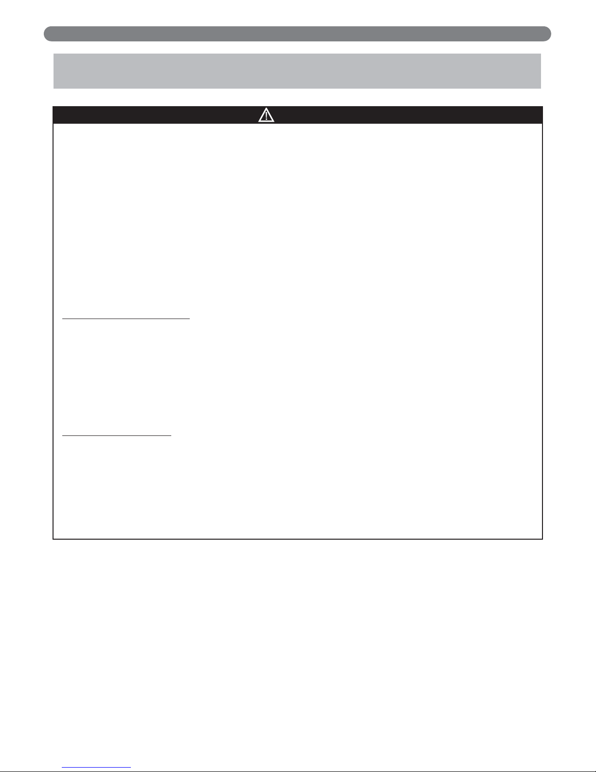
Product Safety Information
Refractory Ceramic Fiber Product
This appliance contains materials made from refractory ceramic fibers (RCF). Airborne RCF,
when inhaled, have been classified by the International Agency for Research on Cancer
(IARC), as a possible carcinogen to humans. After the RCF materials have been exposed to
temperatures above 1800°F (980°C), they can change into crystalline silica, which has been
classified by the IARC as carcinogenic to humans. If particles become airborne during service or repair, inhalation of these particles may be hazardous to your health.
Avoid Breathing Fiber Particulates and Dust
Suppliers of RCF recommend the following precautions be taken when handling these
materials:
Precautionary Measures:
Provide adequate ventilation.
Wear a NIOSH/MSHA approved respirator.
Wear long sleeved, loose fitting clothing and gloves to prevent skin contact.
Wear eye goggles.
Minimize airborne dust prior to handling and removal by water misting the material and
avoiding unnecessary disturbance of materials.
Wash work clothes separately from others. Rinse washer thoroughly after use.
Discard RCF materials by sealing in an airtight plastic bag.
First Aid Procedures:
Inhalation: If breathing difficulty or irritation occurs, move to a location with fresh clean air.
Seek immediate medical attention if symptoms persist.
Skin Contact: Wash affected area gently with a mild soap and warm water. Seek immediate
medical attention if irritation persists.
Eye Contact: Flush eyes with water for 15 minutes while holding eyelids apart. Do not rub
eyes. Seek immediate medical attention if irritation persists.
Ingestion: Drink 1 to 2 glasses of water. Do not induce vomiting. Seek immediate medical
attention.
MAINTENANCE
Page 32

30
MAINTENANCE
A. GENERAL
1. Disconnect this boiler from the gas supply piping
during any pressure testing of the gas system.
2. Check pipes adjacent to cold walls or in unheated
spaces. Insulate and tape them if necessary to be sure
they can’t freeze up. Keeping the water moving at all
times will reduce the likelihood of freezing. See
Section 3 for antifreeze instructions.
3. If there is considerable foreign matter in the boiler
water, the boiler should be shut down and allowed to
cool, then drained and thoroughly flushed out. Use
the drain valve at the bottom of the return connection
to drain the boiler. Pipe the drain cock to a suitable
drain or containment device if antifreeze is used. Flush
the system to remove remaining matter. If there is
evidence that hard scale has formed on the internal
surfaces, the boiler should be cleaned by chemical
means as prescribed by a qualified water treatment
specialist.
B. DAILY (WITH BOILER IN USE)
Daily boiler observation can be performed by the owner.
If any potential problems are found, a qualified installer
or service technician/agency must be notified.
1. Remove any combustible materials, gasoline and
other flammable liquids and substances that generate
flammable vapors from the area where the boiler is
contained. Make certain that the boiler area has
ample air for ventilation and that there are no
obstructions to the free flow of air to and from the
boiler.
2. Observe general boiler conditions (unusual noises,
vibrations, etc.)
3. Observe operating temperature and pressure on the
combination gauge located on the right side of the
boiler. Boiler pressure should never be higher than
5 psi (35 kPa) below the rating shown on the safety
relief valve (25 psig [172 kPa] maximum for a 30 psig
[207 kPa] rating, 45 psig [310 kPa] maximum for a
50 psig [345 kPa] rating). The valve rating can be
found on the top of the safety relief valve (see Figure
3.4 for location of the safety relief valve). Boiler
temperature should never be higher than 250°F
(121°C).
4. Check for water leaks in boiler and system piping.
5. Smell around the appliance area for gas. If you smell
gas, follow the procedure listed in the Operating
Instructions to shut down appliance in Figure 7.3.
C. WEEKLY (WITH BOILER IN USE)
1. Flush float-type low-water cut-off (if used) to remove
sediment from the float bowl as stated in the
manufacturer’s instructions.
D. MONTHLY (WITH BOILER IN USE)
1. Verify condensate drain trap (loop) has sufficient
water to maintain seal and is not blocked. Fill and/or
unblock as necessary.
2. Check boiler room floor drains for proper functioning.
3. Check function of the safety relief valve (monthly
unless specified otherwise by manufacturer) by
performing the following test:
a. Check valve piping to determine that it is properly
installed and supported.
b. Check boiler operating temperature and pressure.
c. Lift the try lever on the safety relief valve to the
full open position and hold it for at least five
seconds or until clean water is discharged.
d. Release the try lever and allow the valve to close.
If the valve leaks, operate the lever two or three
times to clear the valve seat of foreign matter. It
may take some time to determine if the valve has
shut completely.
e. If the valve continues to leak, it must be replaced
before the boiler is returned to operation.
f. Check that operating pressure and temperature
have returned to normal.
g. Check again to confirm that valve has closed
completely and is not leaking.
4. Test low-water cut-off (if used) as described by the
manufacturer.
5. Test limit as described in Section 7, “Check-Out
Procedure.”
6. Test function of gas safety shut-off features as
described by gas valve and ignition control
manufacturer.
E. ANNUALLY (BEFORE START OF HEATING
SEASON)
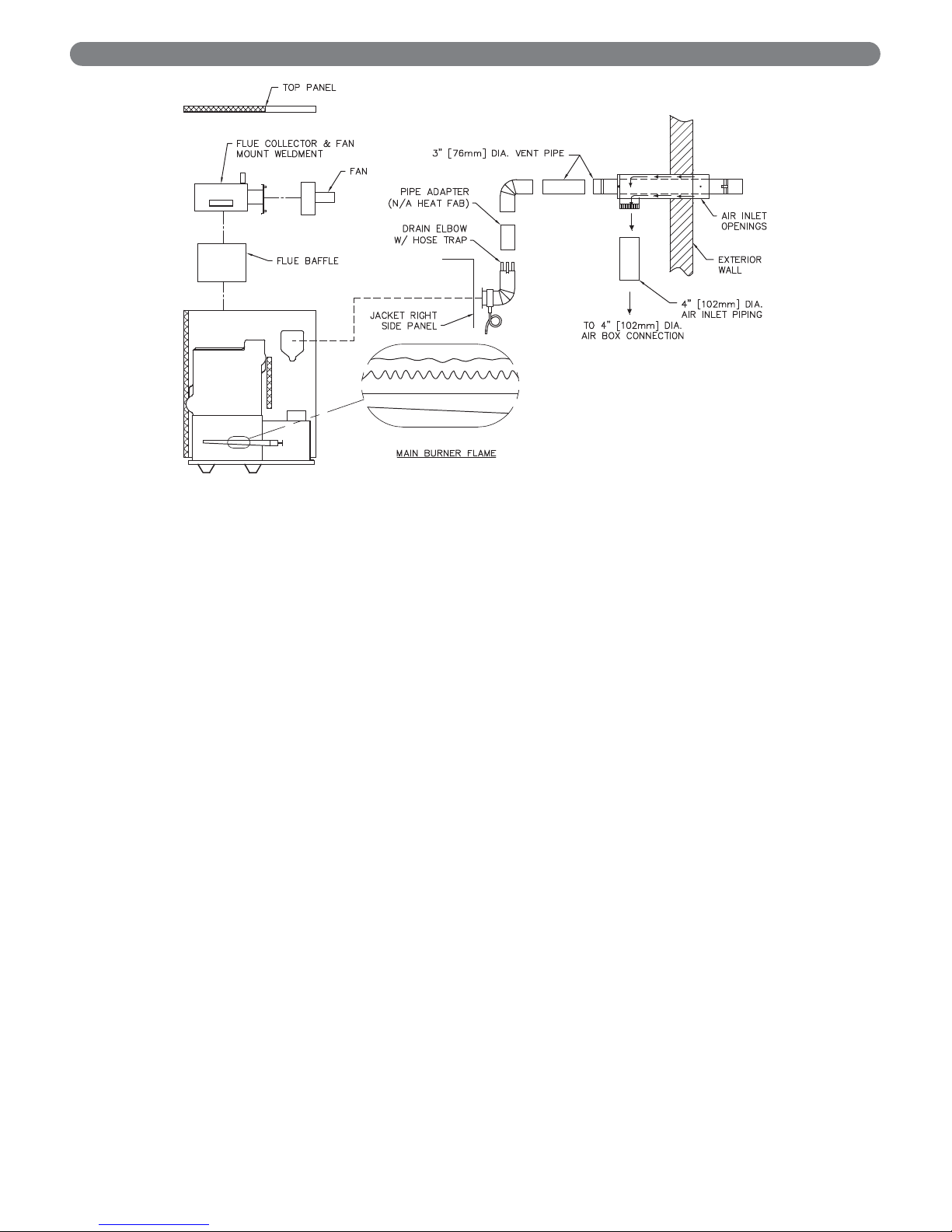
1. Inspect flueways, burners and vent system. See
Figure 9.2.
a. Refer to the Operating Instructions in Figure 7.3 to
properly turn off the gas to the boiler. Turn off all
electrical power to the boiler.
When servicing or replacing components, be
absolutely certain that the following conditions are
met:
●
Water, gas and electricity are off.
●
The boiler is at room temperature.
●
There is no pressure in the boiler.
DANGER
Page 33
31
b. Remove jacket removable door, air inlet pipe, air
box cover, and air box diffuser screen.
c. Remove burner hitch pin clips. Disconnect pilot
tubing at compression elbow.
d. Disconnect pilot harness at gas valve. Gently pull
pilot harness further inside air box to be able to
remove burner with attached pilot.
e. Remove burners and pilot.
f. Brush gas outlet ports lightly using a soft bristle
brush. If extensive corrosion in outlet ports,
replace.
g. Examine pilot hood and igniter for corrosion,
scale, ceramic cracking. Replace if necessary.
h. Remove 3" (76 mm) diameter vent pipe at
condensate elbow or fan outlet.
i. Remove top jacket panel, flue collector/fan
assembly, and flue baffles.
j. Examine flueways and flue collector/fan for scale,
soot, and loose rust.
k. If necessary, brush flueways with wire brush and
remove scale and loose rust from flue baffles. If
corroded, replace baffles.
l. Reinstall flue baffles.
m. Examine flue collector blanket seal.
Reposition/replace as necessary to assure air tight
seal between flue collector and heat exchanger.
n. Reinstall flue collector/fan assembly.
o. Reinstall jacket top panel.
p. Reinstall pilot, burners, hitch pin clips. Reconnect
pilot harness to gas valve, gently pulling harness
to length required to reach gas valve.
q. Reinstall air box diffuser.
r. Examine air box cover seal. Reposition/replace as
necessary to assure air tight seal.
s. Reinstall air box cover.
t. Examine entire vent system for corrosion, support
and joint integrity. Repair as necessary. Remove
any debris inside vent.
u. Reconnect vent pipe to fan adapter. Reseal using
high-temp silicones as shown in Section 4,
Venting, Ventilation and Air Inlet.
v. Refer to Operating Instructions in Figure 7.3 to
properly return the boiler to operation.
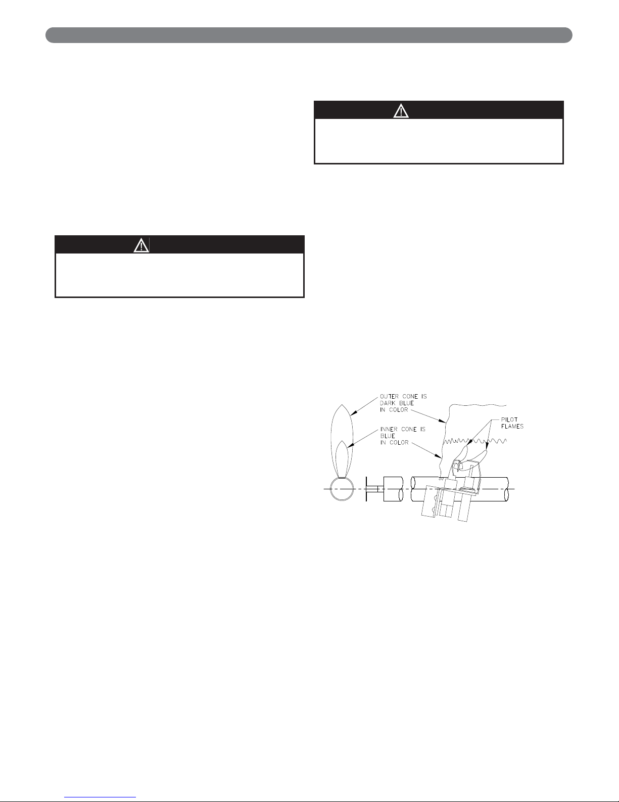
2. Check the pilot and main burner flame. See Figure
9.1. The pilot should provide a steady flame
enveloping 3/8" to 1/2" (1 cm to 1.2 cm) of the flame
sensor. If required, adjust the pilot as stated in the gas
valve manufacturer’s instructions. The main burner
flame inner cone should be approximately
1-1/2" (4 cm) high and should have a very sharp, blue
color characteristic.
Figure 9.1: Intermittent Pilot and Main
Burner Flame
Leaks in the vent system will cause products of
combustion to enter structure (vent system operates
under positive pressure).
WARNING
Soot accumulation indicates boiler malfunction.
Cause of malfunction must be determined and
corrected before returning boiler to service.
WARNING
MAINTENANCE
Page 34
32
MAINTENANCE
Figure 9.2: Inspection of Flueways, Burners, and Vent System.
Page 35
33
10. BOILER DIMENSIONS & RATINGS
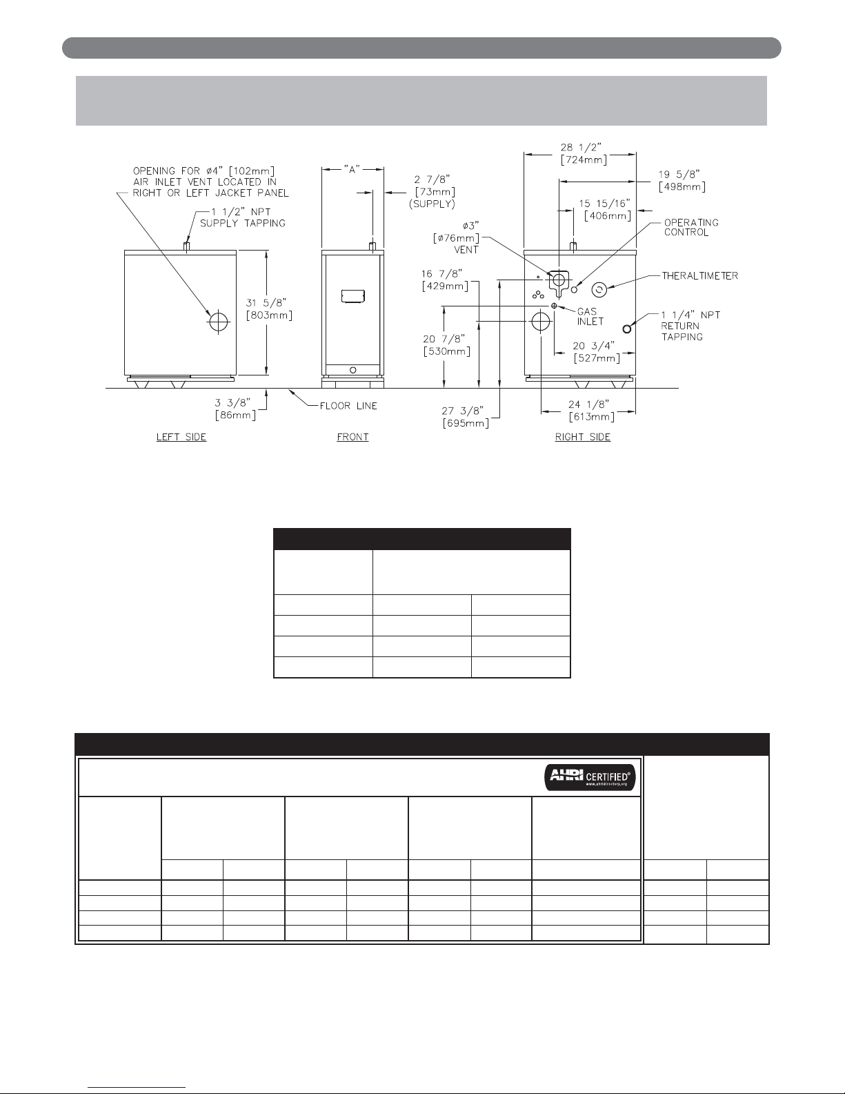
Figure 10.1: Boiler Views
Table 10.1: Series PSC II™ Boiler Dimensions
Table 10.2: Series PSC II™ Boiler Ratings
SERIES PSC II™ BOILER DIMENSIONS
Boiler
Model
Number
Jacket Width “A”
PSCII-03 12-1/2" 318 mm
PSCII-04 15-7/8" 403 mm
PSCII-05 19-1/4" 489 mm
PSCII-06 22-5/8" 575 mm
BOILER DIMENSIONS & RATINGS
1 Net water ratings based on an allowance of 1.15.
2 Consult factory before selecting a boiler for installations having unusual piping and pickup requirements, such as intermittent system operation, extensive piping
systems, etc.
3 Heating Capacity and Annual Fuel Utilization Efficiency (AFUE) ratings are based on U.S. Government test.
SERIES PSC II™ BOILER RATINGS
Series PSC II™
Boiler
Model
Number
Input
DOE Heating
Capacity³
Net Ratings
Water¹,²
Seasonal
Efficiency³
AFUE
MBH kW MBH kW MBH kW %
PSCII-03 65 19 56 16 49 14 86.0
PSCII-04 90 26 77 23 67 20 85.0
PSCII-05 120 35 102 30 89 26 85.0
PSCII-06 150 44 128 37 111 32 85.1
Water
Content
Gallon Liter
4.72 17.87
6.00 22.71
7.28 27.56
8.56 32.40
Page 36
34
REPAIR PARTS
REPAIR PARTS
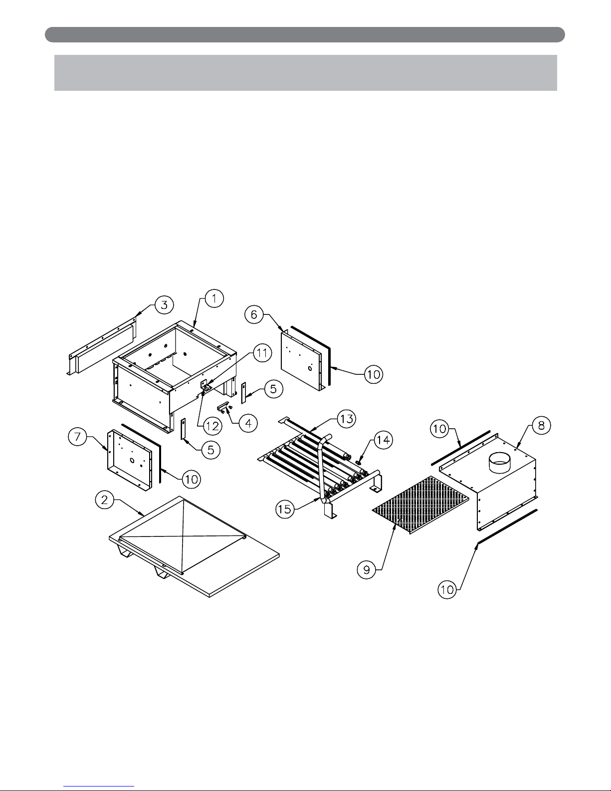
SERIES PSC II™ GAS BOILER
Repair parts are available from your local PB Heat, LLC distributor or from Parts To
Your Door at 1 (610) 916-5380 (www.partstoyourdoor.com).
Note: Remember to include the boiler model number and serial number when ordering parts.
11. REPAIR PARTS
Figure 11.1
Page 37
35
REPAIR PARTS
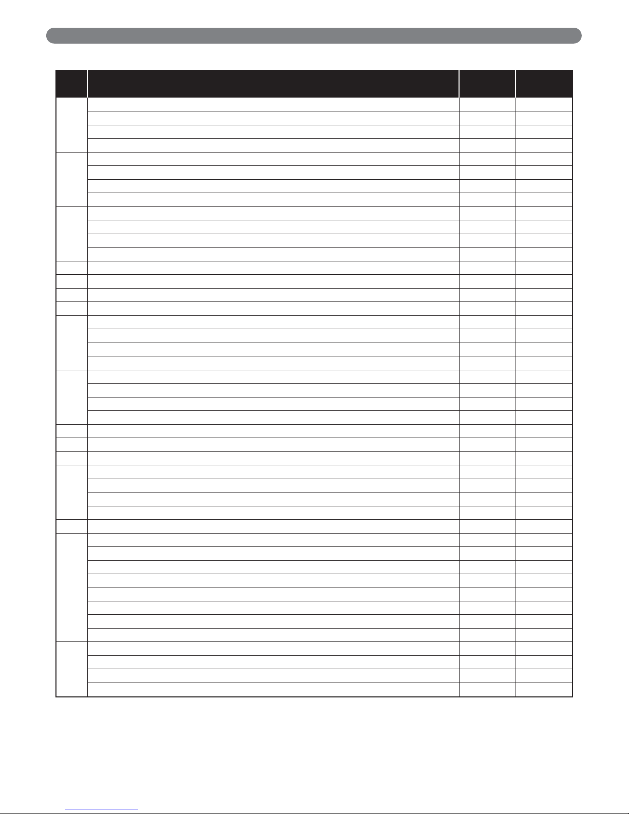
Description
Quantity
Required
Stock
Code
1
Base Assembly – PSCII-03 – 7800
Base Assembly – PSCII-04 – 7801
Base Assembly – PSCII-05 – 7802
Base Assembly – PSCII-06 – 7803
2
Floor Pan – PSCII-03 – 50100
Floor Pan – PSCII-04 – 50101
Floor Pan – PSCII-05 – 50102
Floor Pan – PSCII-06 – 50103
3
Base Rear Panel Assembly – PSCII-03 – PSC2000
Base Rear Panel Assembly – PSCII-04 – PSC2000-1
Base Rear Panel Assembly – PSCII-05 – PSC2000-2
Base Rear Panel Assembly – PSCII-06 – PSC2000-3
4 Base Observation Port Cover – 51771
5 Base/Air Box Spacer – 92 2 50152
6 Air Box Right Side – PSC2023
7 Air Box Left Side – PSC2024
8
Air Box Top/Front Cover – PSCII-03 – 50143
Air Box Top/Front Cover – PSCII-04 – 50144
Air Box Top/Front Cover – PSCII-05 – 50145
Air Box Top/Front Cover – PSCII-06 – 50146
9
Air Box Diffuser Screen – PSCII-03 – PSC2025
Air Box Diffuser Screen – PSCII-04 – PSC2025-1
Air Box Diffuser Screen – PSCII-05 – PSC2025-2
Air Box Diffuser Screen – PSCII-06 – PSC2025-3
10 Rope Gasket Seal, Air Box – 50718
11 Flame Rollout Switch, Thermodisc G4AM00_167C – 51587
12 Flame Rollout Switch Bracket – 50136
13
Steel Burner – PSCII-03 3 51536
Steel Burner – PSCII-04 5 51536
Steel Burner – PSCII-05 7 51536
Steel Burner – PSCII-06 9 51536
– Burner with Pilot Bracket – 51535
14
Orifice, #48, Normal Altitude Natural Gas Only – PSCII-03 4 50894
Orifice, #48, Normal Altitude Natural Gas Only – PSCII-04 6 50894
Orifice, #48, Normal Altitude Natural Gas Only – PSCII-05 8 50894
Orifice, #48, Normal Altitude Natural Gas Only – PSCII-06 10 50894
Orifice, #56, Normal Altitude LP Gas Only – PSCII-03 4 50899
Orifice, #56, Normal Altitude LP Gas Only – PSCII-04 6 50899
Orifice, #56, Normal Altitude LP Gas Only – PSCII-05 8 50899
Orifice, #56, Normal Altitude LP Gas Only – PSCII-06 10 50899
15
Gas Manifold – PSCII-03 – 50121
Gas Manifold – PSCII-04 – 50122
Gas Manifold – PSCII-05 – 50123
Gas Manifold – PSCII-06 – 50124
Table 11.1: Repair Parts
Part numbers may be subject to change without notice.
Page 38
36
REPAIR PARTS
Figure 11.2
Page 39

37
REPAIR PARTS
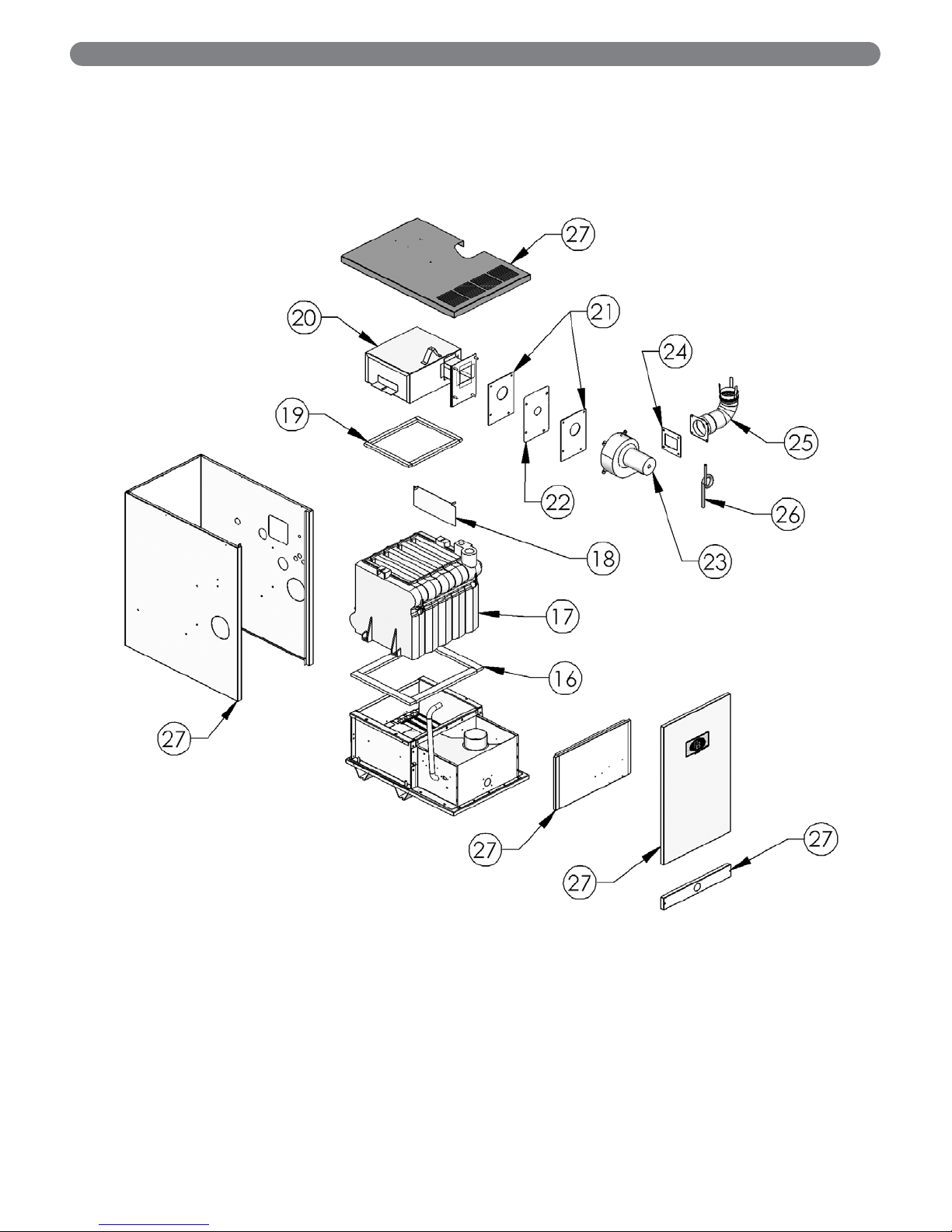
Table 11.2: Repair Parts (see note)
Description
Quantity
Required
Stock
Code
16 Insulation Blanket, 1/2" x 1.50", Block to Base – 50867
17
Block – PSCII-03 – 90419
Block – PSCII-04 – 90420
Block – PSCII-05 – 90421
Block – PSCII-06 – 90422
18
Flue Baffle – PSCII-03 2 51584
Flue Baffle – PSCII-04 3 51584
Flue Baffle – PSCII-05 4 51584
Flue Baffle – PSCII-06 5 51584
19 Insulation Blanket, 1/2" x .75", Flue Collector to Block – 50866
20
Flue Collector – PSCII-03 – 50171
Flue Collector – PSCII-04 – 50172
Flue Collector – PSCII-05 – 50173
Flue Collector – PSCII-06 – 50174
21 Gasket, Orifice Plate 2 50135
22
Orifice Plate, Normal Altitude Natural Gas Models Only – PSCII-03 – PSC5002
Orifice Plate, Normal Altitude Natural Gas Models Only – PSCII-04 – PSC5002-1
Orifice Plate, Normal Altitude Natural Gas Models Only – PSCII-05 – PSC5002-2
Orifice Plate, Normal Altitude Natural Gas Models Only – PSCII-06 – PSC5002-3
Orifice Plate, Normal Altitude LP Gas Models Only – PSCII-03 – PSC5003
Orifice Plate, Normal Altitude LP Gas Models Only – PSCII-04 – PSC5003-1
Orifice Plate, Normal Altitude LP Gas Models Only – PSCII-05 – PSC5003-2
Orifice Plate, Normal Altitude LP Gas Models Only – PSCII-06 – PSC5003-3
23 Fan – 50775
24 Fan Adapter – 50200
25
Jacket – PSCII-03 – 90729
Jacket – PSCII-04 – 90730
Jacket – PSCII-05 – 90731
Jacket – PSCII-06 – 90732
– Gas Valve, VR8204A2001, Natural Gas Models Only – 50583
– Gas Valve, VR8204A2183, LP Gas Models Only – 50584
– Pressure Switch, Standard Altitude, .46" W.C. PSCII-03 – 50026
– Pressure Switch, Standard Altitude .50” W.C. PSCII-04/05 – 50025
– Pressure Switch, Standard Altitude .42” W.C. PSCII-06 – 50024
– Safety Relief Valve, 30 PSI, Conbraco 10-408-05 – 50501
– Safety Relief Valve, 50 PSI, Watts #350 – 99950
– Temperature-Pressure Gauge – 51774
– Condensate Drain Elbow – 51185
– Outside Stainless Steel Vent Cap – 50139
– Wall Thimble (standard, up to 11-1/2" wall) – 50137
– Wall Thimble 20 (for a wall greater than 11-1/2" to 20") – 90350
– Inside Thimble Cap – 50138
– Inside Thimble Collar – 50158
– Screened Vent Termination – 50130
– Vent Clamp – 51900
– Limit Control, Beckett AquaSmart 7600B – 50335
– Immersion Well, Beckett 7600T – 50341
– Immersion Sensor, Beckett 7600P – 50339
– Limit Control, Hydrolevel HydroStat 3200 – 50334
– Immersion Well, Hydrolevel – 50723
– Ignition Module, Honeywell S8610 – 50672
– Pilot, Nat Gas, Q348A1002 – 50558
– Pilot, LP Gas, Q348A1358 – 51814
– Ignition Cable – 50640
– Relay, 24VAC Coil, DPST – 50726
Blower Gaskets
– Orifice Plate Gaskets 2 50135
– Fan Outlet Gasket – PSC5019
Note: Consult factory for control system repair parts for models with SmartValve ignition system. Furnish vendor part number of control that needs to be
replaced and boiler serial number.
Part numbers may be subject to change without notice.
Page 40
PSC
II
™
Boilers
Series
Gas
Installation,
Operation &
Maintenance
Manual
TO THE INSTALLER:
This manual is the property of the owner and must
be affixed near the boiler for future reference.
TO THE OWNER:
This boiler should be inspected annually by a
Qualified Service Agency.
PSC8078 R1 (6/15-5C)
Printed in U.S.A.
©2015 PB Heat, LLC. All rights reserved.
PB HEAT, LLC
131 S. CHURCH STREET • BALLY, PA 19503
 Loading...