

PeerlessBoilers ECT-03-120, ECT-04-125, ECT-04-150, ECT-04-175, ECT-05-175 Installation, Operation & Maintenance Manual
...Page 1
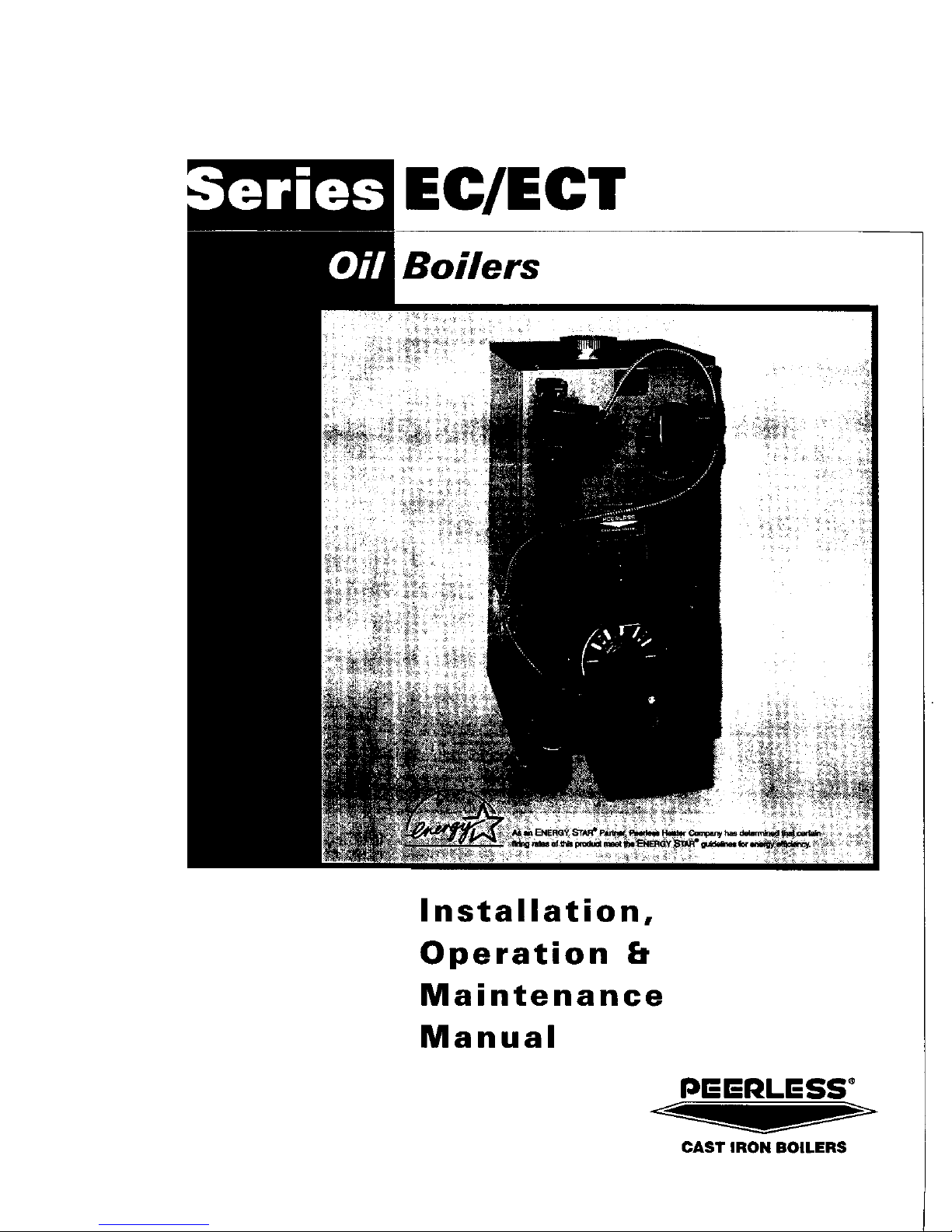
EC/ECT
Boilers
Installation,
Operation b
Maintenance
Manual
Pr=-r=-I_LESS"
CAST IRON BOILERS
Page 2

Packaged or Knockdown, Hot Water or Steam Boilers
11 Sizes 3-6 Sections .75 to 3.0 GPH Input 82.9% to 86.6% AFUE
Natural Draft (chimney) Venting
Factory Assembled Sections on Knockdown Boilers
• Reduces Installation Time
High Efficiency Flame Retention Burners
• Choice ofBeckett, Carlin or Riello
Full Plate Swing-Out Door
• Standard on All Boilers
• Provides Easy Access to Combustion Chamber AreaJor Cleaning and Servicing
Large Water Content, Wet Base Section Design
• Ideal for Steam and Large Volume Hot Water Applications
Steel Push Nipples
• Provide a Permanent Woter Tigh[ Seal Between Sections
• Unaffected by Petroleum and Other Contaminants
Easy to Clean
• Flueways carl be Cleaned from Either the Left Side or Top
Deluxe Insulated Enameled Steel Jacket
• Reduces Boiler Heat Loss
Safety Controls
• Probe or Float Type Low Water Cut OffApprovr_d on Steam Boilers
Tankless Coils
• For Domestic Hot Water Production on Hot Water Boilers
• Honeywell Operating Controls
• Barometric Draft Damper
• Taco 007 Circulalor on Packctged WcJler Boilers
• Float Type LWCO on Packagt'd Steam Boilers
\ Ix .,,p_o__ I
• "l_mkless Coils
• Gnlnc!lbs Circulalor on Pctckaged Water Boilers
.,,_ *Pcob<" Tt.ip_" LWCO olt Packaged Sly,am Boilers
P_'_I'It'ss Boilers is i)It'as_'_{ to QI]_'I oll(' QJ l]lt" IIl()sl co_lpr_.lll'llsit,t' iP(llT_lill_] i)fofjFQlll._ ill lh(' ill(_lisll_t]. All Pt,t'_l(_ss r(,sid_'tlti_ll
casl i!ott I)oilt'is irlt'ltt_l_" _t {illl oae ycat tP(llTTII!l{I. A [Jlllilt'tl. l([i'limt' tt,(¢lr(ull{I is ptY)l,i(]t'({ [or lilt" ('(isl iroii ._t'clioiIs o[ P_'('i[('_s
rz'sidt'llliQl ttot It'(lll'I t)oilt't,_. Pt't'rlt',_s also t)r_)t'itl_'s _l liIIlil+'_l I('ll []t'(ll II'(ll'l'Cllll!] Oll IIR" ('CISl il_)l] _;t'('liOIIS Q]'ilS r('_i(l('Illi(I/ slt'Cllfl
I)oilt'Is. l;'it,_" _llld ll'll !]('(l! <t','li'_Kl_'(I [t,(ll'l'(lll_it'_q ()It 131111.% (lli(l Itll)Ol CIl'(' IIolt, (IP_lil(l!)l_'. PI<'_i.';_' ('Oll.'_llll P('('tl('._.'_ [$oil('r.'_ li)r ('OllllIl('l('
{f!(ll'l'(lllll] it!Jorm(lliol£.
Peerless Boilers * 610-367-2153 • www.peerless-heater.eom
FAB EC R_{303 IM)
Prrn_l d _ll U S A
Page 3
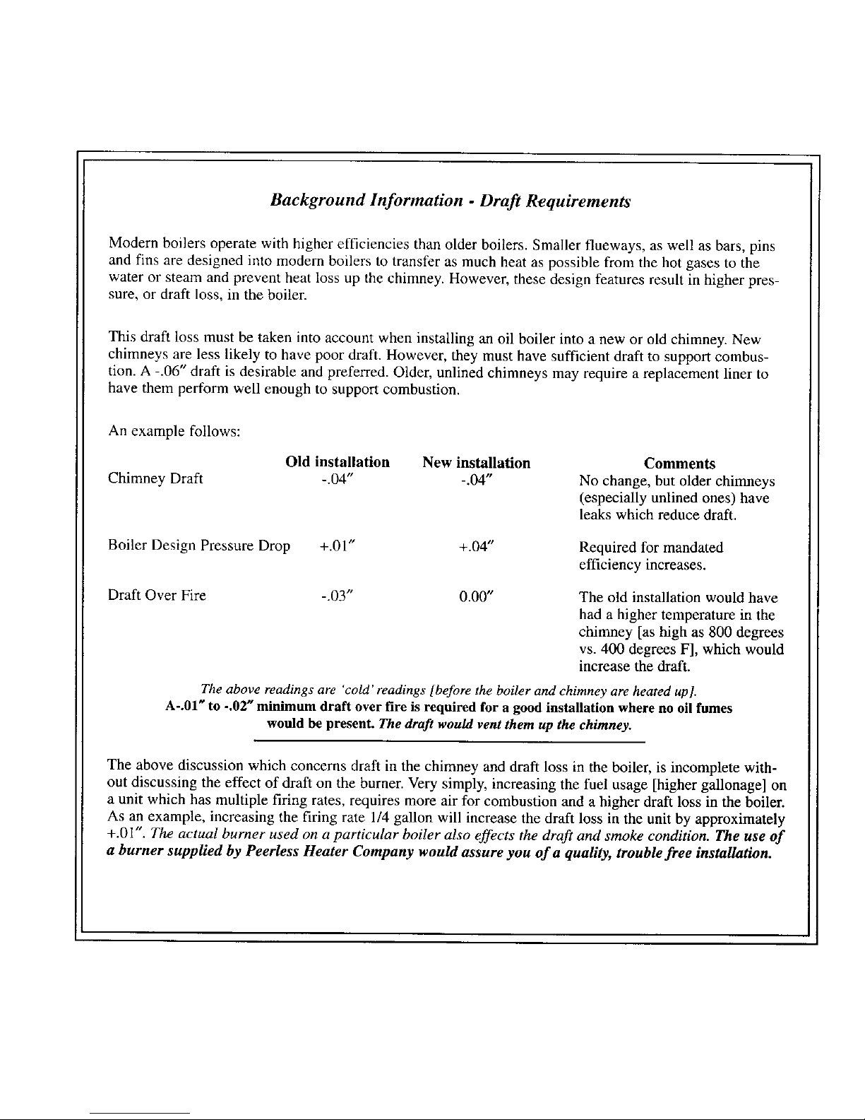
Background Information - Draft Requirements
Modern boilers operate with higher efficiencies than older boilers. Smaller flueways, as well as bars, pins
and fins are designed into modem boilers to transfer as much heat as possible from the hot gases to the
water or steam and prevent heat loss up the chimney. However, these design features result in higher pres-
sure, or draft loss, in the boiler.
This draft loss must be taken into account when installing an oil boiler into a new or old chimney. New
chimneys are less likely to have poor draft. However, they must have sufficient draft to support combus-
tion. A -.06" draft is desirable and preferred. Older, unlined chimneys may require a replacement liner to
have them perform well enough to support combustion.
An example follows:
Chimney Draft
Old installation New installation
-.04" -.04"
Comments
No change, but older chimneys
(especially unlined ones) have
leaks which reduce draft.
Boiler Design Pressure Drop +.01" +.04"
Required for mandated
efficiency increases.
Draft Over Fire -.03" 0.00"
The old installation would have
had a higher temperature in the
chimney [as high as 800 degrees
vs. 400 degrees F], which would
increase the draft.
The above readings are 'cold' readings [before the boiler and chimney are heated up].
A-.01 _ to -.02" minimum draft over fire is required for a good installation where no oil fumes
would be present. The draft would vent them up the chimney.
The above discussion which concerns draft in the chimney and draft loss in the boiler, is incomplete with-
out discussing the effect of draft on the burner. Very simply, increasing the fuel usage [higher gallonage] on
a unit which has multiple firing rates, requires more air for combustion and a higher draft loss in the boiler.
As an example, increasing the firing rate 1/4 gallon will increase the draft loss in the unit by approximately
+.01". The actual burner used on a particular boiler also effects the draft and smoke condition. The use of
a burner supplied by Peerless Heater Company wouM assure you of a quality, trouble free installation.
Page 4
INSTALLATIONINSTRUCTIONS- SERIESECand ECT
Readcarefullybeforebeginningwork.Itwillsavetime.Studythe includeddrawings.
This boilermust beinstalledbya qualifiedcontractor.
Theboilerwarrantycan bevoidedifthe boileris not installed,maintained,andservicedcorrectly.
Theequipmentshallbe installedinaccordancewiththoseinstallationregulationsinforce inthelocalareawheretheinstallationisto bemade,includingthe
currenteditionof NFPA-31.Theseshallbecarefullyfollowedin allcases.Authordieshavingjurisdictionshallbeconsultedbeforeinstallationsaremade.
A- ACCESSIBILITYCLEARANCES
1 - To provide for reasonableconditionsof accessibilityfor servicing,the following minimumclearancesare recommendedbetweenthe boiler and
adjacentwallsor otherappliances--atleast24" inthe front,rearandonboth sides.
B- AIRFORCOMBUSTIONANDVENTILATION
1- Becertainadequatefacilitiesareavailableto provideairfor satisfactorycombustionandventilation.
2- AppliancesLocatedinUnconfinedSpaces.
a. For installationsin unconfinedspaceswith conventionalconstructionandlargeareas suchas basements,the supplyof air for combustionand
ventilationcanusuallybe consideredadequate.
3- AppliancesLocatedinConfinedSpaces.
a. If all air for combustionandventilationis to comefromwithinthebuilding;twoopenings,onenearthe ceilingandone nearthe floorofthe boiler
roomshallbe providedwiththe minimumfreearea ofeachopeningequalto 140sq.in.pergallonofoil burned.
b. If all airfor combustionandventilationisto comefromoutsidethebuilding;twoopenings,one neartheceilingand one nearthefloorofthe boiler
roomshallbeprovidedwiththeminimumfreeareaof eachopeningequalto 35sq.in. pargallonofoil burned.Ifductsare usedto conveytheair,
areasof35 sq.in.pergallonofoil burnedfor verticalductsor 70 sq.in.per gallonofoil burnedfor horizontalductsareto beprovided.Ductsshall
havethesame areaasthefreeareaof theopeningstowhichthey areconnected.
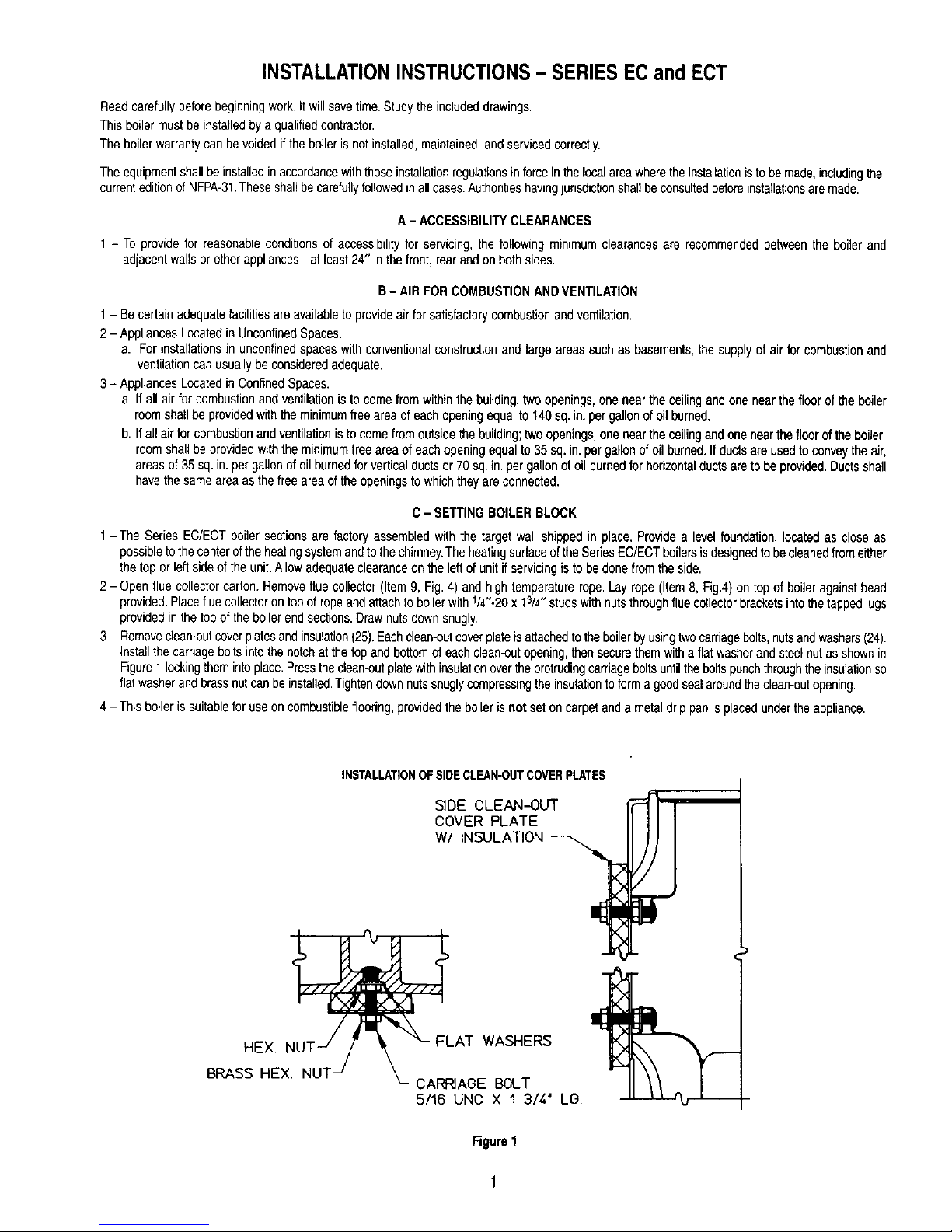
C- SETTINGBOILERBLOCK
1-The SeriesEC/ECT boilersectionsare factoryassembledwiththe target wallshippedin place. Providea levelfoundation,locatedas close as
possibletothecenteroftheheatingsystemandto thechimney.TheheatingsurfaceoftheSedesEC/ECTboilersisdesignedtobecleanedfromeither
thetopor left sideofthe unit.Allowadequateclearanceon the leftof unitif servicingisto bedonefromthe side.
2- Openfluecollectorcarton.Removefluecollector(Item9, Fig. 4) andhightemperaturerope.Lay rope(Item8, Fig.4) ontop of boileragainstbead
provided.Placefluecollectorontop of ropeand attachto boilerwith1/4"-20x13/4"studswithnutsthroughfluecollectorbracketsintothetappedlugs
providedin thetopof the boilerendsections.Drawnutsdownsnugly.
3- Removeclean-outcoverplatesandinsulation(25).Eachclean-outcoverplateisattachedtothe boilerbyusingtwocarriagebolts,nutsandwashers(24).
Installthe carriageboltsintothenotchatthe top andbottomof eachclean-outopening,thensecurethemwith a flatwasherandsteelnutasshownin
Figure1 lockingthemintoplace.Pressthe clean-outplatewithinsulationoverthe protrudingcarriageboltsuntiltheboltspunchthroughtheinsulationso
flatwasherandbrassnutcanbeinstalled,Tightendownnutssnuglycompressingthe insulationto forma goodsealaroundthecleen-outopening,
4- This boileris suitableforuseon combustibleflooring,providedthe boilerisnot seton carpetand a metaldrippanis placedundertheappliance.
INSTALLATIONOF SIDECLEAN-OUTCOVERPLATES
5/16 UNC X 1 3/4" L(3.
Figure1
Page 5
D- SWINGDOORANDOBSERVATIONCOVERASSEMBLY
1- Removeburnermountingplateincludingrightsidemountingstudsfor burnermountingplate(donot removeleftsidestuds)
2- CollecttheSwingDoorCarton(90924)containingthehingeassemblyandhardware.
3- InstallInternalHingeP/NEC1021(Item6, Fig,4)to frontsectionof boilerwith(2)5/16-18UNCx 3/4"hex headcapscrewsand5/16"flatwashers(do
netusethe11/4" longscrews).
4- InstallExternalHingeP/NEC10122(Item7, Fig.4) to theoutsideoftheburnermountingplatewith(2)5/16-18UNCx 11/4" hexheadcapscrews,flat
washers,andnuts.Thecapscrewsshouldbeinsertedthroughthe backoftheburnermountingplate,thenthroughthe hinge.Do NOTtightenExternal
Hingescrewsat thistime.Thiswillallowforalignmentofthe plateonceitis placedinposition.
5- Hangburnermounting plate in position,then close to alignthe remainingthree (3) studson leftside of section.Once alignmentis accomplished,
tightennutson ExternalHinge.DeNOTreinstallnuts!washerson left sidestudsuntilafterjacketinstallation.
6- Removeobservationdoor (Item4, Fig.4) frominsideburnermountingplate.Attachthe observationdoortothe outsideofthe mountingplate.
7- Theremainingswingdoorcartonpartswillbe usedinSectionH,Wiring.
E - JACKETASSEMBLY
1- Referto Page4,Fig,4forexplodedview.Attachthebackpanel(19)tobossesonmiddleofbacksectionwithtwo 1/4"x3/8"trussheadmachinescrews
(20) provided.Thebackpanelhastwo shG"diameterholesclosetothe centerof thepanel.
2- Liftoff theburnermountingplate.Placeeerafeltliner(28)on floorof boilerin frontoftargetwall.
3- Removethe (2)knock-outsinthefrontjacketpanel(23)whichallowclearanceforthehinge.Placethefrontjacketpanelonthe blockand replacethe
burnermountingplate.
4- Attachrightside jacketpanel(22)tothe frontandbackpanelswithsheetmetal screws,
NOTE:ON SERIESECTBOILERS,THEOPTIONALWATERHEATER(17) MUSTBEINSTALLEDINLARGEOPENINGIN BACKSECTION
BEFORETHE LEFTSIDE JACKETPANELSAREATTACHED.
5- Ifwater heaterisused, removeknockout piecesin upperleft side jacketpanel(21)and backjacketpanel(19) beforeinstalling.Attachleftsidejacket
panelsin thesamemanneras the rightsidepanel.
6- Attachthetop panel.Thetop ismadeintwopieces(26&27).Join thetwopiecestogetherwithsheetmetalscrews.Securetoppaneltofrontand back
panelwithsheetmetalscrews.
7- Install waterheater(13)whenrequired,inlargeopeninginfrontofboiler.SeeFigure3Aor3Bforsuggestedpiping.Whenwaterheaterisnotemployed,
coverthe heateropeningwithcoverplate(12)or (16).
BESURERUBBERGASKETISIN PLACEBETWEENCOVERPLATEORWATERHEATERPLATEANDBOILERSECTION.
Page 6
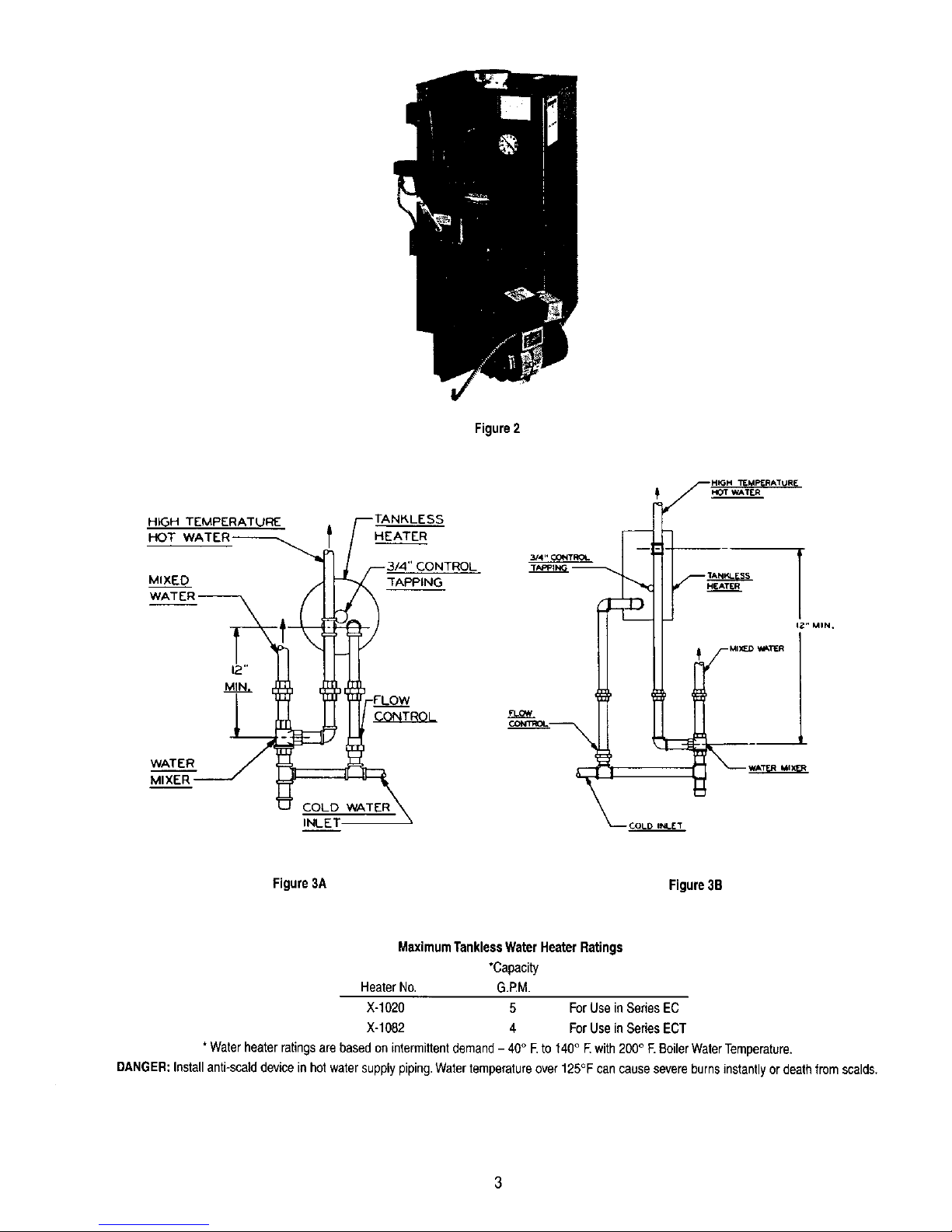
Figure2
HIGH TEMPERATUFE
HOT
MIXED
WATER
MIXER
COLD
INLET
HEATER
7lAPPING
CONTROL
3/4" OOfl'rROL -- I_" MIN.
Figure3A Figure3B
MaximumTanklessWaterHeaterRatings
*Capacity
HeaterNo. G.F_M.
X-1020 5 FurUse inSeriesEC
X-t082 4 ForUse inSeriesECT
*Waterheaterratingsarebasedon intermittentdemand- 40° F.to140° E with200° F.BoilerWaterTemperature.
DANGER:Installanti-scalddeviceinhotwatersupplypiping.Watertemperatureovert25°F cancausesevereburnsinstantlyordeathfromscalds.
Page 7

27
_26
-N
._h c
J_h
F4
Page 8

ItemNo.
1
SERIESECand ECT
Part No.
EC-1001
EC-1001-1
X-1096
X-!096-1
EC-10O2
EC-1OO2-1
X-1097
X-1097-1
X-3019
X-1060
X-1031
X-1061
EC-1021
EC-1022
Description
BlockAssembly- EC-03
BlockAssembly- EC-04
BlockAssembly- EC-05
BlockAssembly- EC-06
BlockAssembly- ECT-03
BlockAssembly- ECT-04
BlockAssembly- ECT-05
BlockAssembly- ECT-06
TargetWall
BurnerMountingPlate
ObservationDoor
5/16"-18x 2-1/4" Studsw/Nuts- 5 Req'd
SwingOutBurnerMountingPlateHinge- Internal
SwingOutBurnerMountingPlateHinge- External
HighTemp.Rope3/8" Diameter.48" Long
HighTemp.Rope3/8" Diameter.56" Long
HighTemp.Rope3/8" Diameter.64" Long
HighTemp.Rope3/8" Diameter.72" Long
FlueCollector
FlueCollector
FlueCollector
FlueCollector
1/4"-20x 1-3/4" Studsw/Nuts- 2 Req'd
RubberGasket
CoverPlate
TanklassCoil(OptionalWaterOnly)
3/8"-16x 3/4" HexHal.CapScrews- 6 Req'd
RubberGasket(ECTModels)
CoverPlate(OptionalECTModels)
TanklessHeater(OptionalECTModels)
3/8"-16x 3/4" Hex Hd.CapScrews- 8 Req'd
BackJacketPanel
1/4"-20x 3/8"Truss Hd,Mach.Screws- Cad,Plate- 2 Req'd
UpperLeftSideJacketPanel
UpperLeftSideJacketPanel
UpperLeftSideJacketPanel
UpperLeftSideJacketPanel
EC/ECT-03
X
x
X
X
2 X x
3 X X
4 X X
5 X X
6 X X
7 X X
8 X
X
9 EC-50O0 X
EC-5000-1
EC-5000-2
EC-5000-3 X
10 X-5000 X X
11 X-1023 X X
12 X-1034 X X
13 X-1020 X X
14 X X
15 X-1083 X X
16 X-t084 X X
17 X-t082 X X
18 X X
19 EC-6003 X X
20 X X
21 EC-6007 X
EC-6007-1
EC-6007-2
EC-6007-3 X
ModelNo.
EC/ECT-04 EC/ECT.O5
X
X
X
X
X X
X x
X X
X X
X X
X X
X
X
X
X
X X
X X
X X
X X
X X
X X
X X
X X
X X
X X
X X
X
X
EC/ECT-06
Page 9

ItemNo.
21A
SERIESECand ECT
PartNo.
EC-6008
EC-6008-1
EC-6008-2
EC-6008-3
EC-6O02
EC-6002°1
EC-6002-2
EC-6002-3
EC-6000
Description
LowerLeftSideJacketPanel
LowerLeft SideJacketPanel
LowerLeft SideJacketPanel
LowerLeft SideJacketPanel
RightSideJacketPanel
RightSideJacketPenet
RightSideJacketPanel
RightSideJacketPanel
FrontJacketPanel
5/18"-18x 1-3/4" CarriageBoltw/Nuts
SideClean-OutCoverPlate
RightTopJacketPanel
RightTopJacketPanel
RightTopJacketPanel
RightTopJacketPanel
LeftTopJacketPanel
LeftTopJacketPanel
LeftTopJacketPanel
LeftTopJacketPanel
BaseLiner
BaseLiner
BaseLiner
BaseLiner
EC/ECT-03 EC/ECT-06
X
X
22 X
X
23 X X
24 X X
25 X-1085 X X
26 EC-6005 X
EC-6005-1
EC-6005-2
EC-6005-3 X
27 EC-6004 X
EC-6004-1
EC-6004-2
EC-6004-3 X
28 EC-3000 X
EC-3000-1
EC-3000-2
EC-30O0-3 X
ModelNo.
EC/ECTo04 EC/ECT-05
X
X
X
X
X X
X X
X X
X
X
X
X
X
X
E - PIPING
DONOTPIPEBOILERUNTILAFTERJACKETISINSTALLED.
1- See Figures5 and 6 forsuggestedpipingtothe boiler.Also,seeHydronicsInstituteResidentialHydronicHeatingGuide2000.
2- Makeupcold watersupplyconnectiontothe boiler.
3- Installpressuregaugeortemperature-pressuregaugein tappingprovided.SeeFigure9.
4- Pluga!lopen tappingsin the boilerandfill withwater.Applyapproximatelythirty(30) poundspressure.Checktomakecertainthatalljoints
andfittingsare watertight,
5- Afteralljointsand connectionshavebeenprovenwatertight,removecoldwatersupplyandplugsfromall tappingsthat areto be used.See Figure
9for tappinglocations.
6- The returnpipingto the 1-1/4" NPT lowertappingonthe frontsectionmustbe installedin sucha mannerto assureproperclearanceof the oil
burnerandmountingplatewhenopeningandclosing the burnermountingplate.Peerlesssuggestsusinga 1-1/4"90 degreestreetelbowat this
lowertappingin orderto positionthereturnpipingawayfromthe mountingplateassembly.
NOTE:IFTHISBOILERANDDISTRIBUTINGSYSTEMIS USEDiNCONJUNCTIONWITHAREFRIGERATIONSYSTEM,THECHILLEDMEDIUM
SHALLBE PIPEDIN PARALLELWITHTHEBOILERANDTHE PROPERVALVESAPPLIEDTO PREVENTTHECHILLEDMEDIUMFROM
ENTERINGTHEBOILER.WHENTHEBOILERISCONNECTEDTOHEATINGCOILSLOCATEDINAIRHANDUNGUNITSWHERETHEY
MAYBEEXPOSEDTOREFRIGERATEDAIRCIRCULATION,THEBOILERPIPINGSYSTEMMUSTBEEQUIPPEDWITHFLOWCONTROL
VALVESOROTHERAUTOMATICMEANSTOPREVENTGRAVITYCIRCULATIONOFTHEBOILERWATERDURINGTHECOOLINGCYCLE.
Page 10

I
\ i i
ERON[
ID
_ EQUALIZER
X
REAR
FRONT REAR
Boiler
Model
No, Risers Header Equalizer
EC/ECT-03-075 1-2" 11/4"
EC/ECT-03-1O0 1-2" 1V4"
EC/ECT-03-120 1-2" 1V4"
EC/ECT-04-125 2-2" 21/2', 11/2"
EC/ECT-04-150 2-2" 21/2", 11/2"
EC/ECT-04-175 2-2" 21/2" 11/2"
EC/ECT-05-175 2-2" 3" 11/2"
EC/ECT-05-200 2-2" 3" 11/2"
EC/ECT-05-250 2-2" 3" 11/2"
EC/ECT-06-275 2-2" 3" 1112"
EC/ECT-06-300 2-2" 3" 11/2"
Thereturnfrom systemshouldalwaysenterequalizerthrough
HartfordLoop,2" to4" belownormalwaterline (seedimensional
drawingfornormalwaterline).
STEAM
Figure5
Sizethesupplyand returnconnectionsto suit thesystem.
Pipethe supplyandreturninoneoftwoways:
1) Pipethesupplyfromthetop ofthe rearsectionand
returntothe bottomof thefrontsection.Use the 3/4"
tappinginthe topof thebacksectionforairelimination.
2) As an acceptablealternative,pipethesupplyfromthe
topof thefrontsectionandreturntothe bottomofthe
rearsection.Providean aireliminationmeanswithinthe
supplypiping.
HOTWATER
ALTERNATE
SUPPLY
FRONT
r
ALTERNATE
RETURN
REAR
Figure6
F- OILBURNERINSTALLATION
1- Theoilburneris suppliedwitha mountingflangefixedinposition.
2- Mountthe burnerto theburnermountingplate(3)Figure4 withfour5/16"studsandnutsprovided.
BESUREHIGHTEMPGASKETISBETWEENTHEBURNERMOUNTINGFLANGEANDTHE BURNERMOUNTINGPLATE.
3- Routethe oillinesto avoidinterferencewhenopeningthe platefor boilerservicing.Useflexibleoillinesorcopper.Whenusingflexibleoillines,
providetubinglongenoughto allowthe plateto swingfreelyoveritsentirerange.Whenusingcopper,installflaredcopperdisconnectswithvalves.
4- See Figure7for OilBurnerSpecifications.If exceeding100PSIpumppressureon burnersshownat100PSI,seechartonpage13to determine
therequiredreductioninnozzlesize.
7
Page 11

WAYNE BURNER WITH 100 PSI PUMP PRESSURE
Boiler Burner Air Cone Nozzle Start-UpSettings
ModelNo, ModelNo, I,D, Size FlameLock Off-CycleDamp, AirShutter
EC/ECT-03-075 HS 21/2" NoHoles .7580°A DEL 1 1.0 .50
EC/ECT-03-100 HS 21/2" NoHoles 1.0080"B DEL 1 1.2 1.50
EC/ECT-03-120 HS 21/2"NoHoles 1.2080°B DEL 11/2 1.5 1.75
EC/ECT-04-125 HS 21/2" 6Holes 1.2580°B DEL 1 2.0 2.00
EC/ECT-04-150 HS 21/2" 6Holes 1.5080°B DEL 3 2,0 2.25
EC/ECT-04-175 HS 21/2" 6Holes 1.7580°B DEL 5 2,0 2.50
EC/ECT-05-175 HS 21/2" 6Holes 1.7580°B DEL 5 2.0 2.50
EC/ECT-05-200 HS 21/2" 6Holes 2.00 80° B DEL 5 2,0 3.50
EC/ECT-05-250 HS 21/2" 6Holes 2.50 80° S DEL 8 2.0 5.00
EC/ECT-06-275 HS 3-5/16" Str.Bore 2.7580°B DEL 2 2,0 4.00
EC/ECT-06-300 HS 3-5/16'` Str.Bore 3.00 80° B DEL 2 2.0 4.50
CARLIN BURNER
Boiler Burner Start-UpSettings
ModelNo. ModelNo. Air Shutter NozzleSize PumpPressure HeadDim.A Air Band
EC/ECT-04-125 *99FRD Blank 1.00x 70°B DEL 150 PSI 2 40%open
EC/ECT-04-150 *99FRD Blank 1.25x 60°B DEL 150 PSI 3 60%open
EC/ECT-04-175 *99FRD Blank 1,50x 60°B DEL 150 PSI 4 100%open
EC/ECT-05-175 *99FRD Open 1,50x 60° B HAGO 150 PSI 5 10%open
EC/ECT-05-200 *99FRD Open 1,65x 60° B HAGO 150 PSI 5 45%open
EC/ECT-05-250 *99FRD Open 2,00x 60° B HAGO 150 PSI 8 100%open
EC/ECT-06-275 102CRD Open 2,75x 60°B DEL 100 PSI 7 100%open
EC/ECT-06-300 102CRD Open 3,00x 60°B DEL 100 PSI 9 100%open
*Model99FRDBurnerEquippedwithModel 98022PSCMotor
CARLINEZ-IHP OILBURNERWITHMODEL98022PSC MOTOR
Boiler Burner Start-UpSettings
ModelNo, FiringRate ModelNo, AirShutter NozzleSize PumpPressure AirBand HeadBar
EC/ECT-03-075 .75 EZ-1HP Blank 0.60 x70° BDEL 150 PSI 0.55 0.60- 0.65
EC/ECT-03-100 1.00 EZ-1HP Blank 0.85x70° A DEL 150PSI 0.65 0.85- 1.00
EC/ECT-03-120 1.20 EZ-1HP Blank 1.00x70° A DEL 150PSI 0.80 0,85- 1.00
BECKETTBURNERWITH140 PSIPUMPPRESSURE
Boiler Burner Burner Static Nozzle Start-UpSettings Head
ModelNo. ModelNo. Head Plate Size AirShutter AirBand Setting
AFG-LI* LI* 33/8" .6560" BHAGO 9.0 2 N/A
AFG-L1 L1 33/8" .8560° BHAGO 10.0 1 N/A
AFG-L1 L1 ** 1.0060° B HAGO 9.0 2 N/A
AFG-F6 F6 23/4" 1.1080° A DEL 5.0 1 N/A
AFG-F6 F6 23/4" 1.2580° BHAGO 8.0 1 N/A
AFG-F6 F6 23/4" 1.5080° B HAGO 10,0 3 N/A
AFG-MV1 M-V1-3 -- 1.5060°B HAGO 10.0 3 3
AFG-MV1 M-V1-3 -- 1.7560° B HAGO 10,0 9 3
AFG-MV1 M-V1-5 -- 2.0045° BHAGO I0.0 5 5
CF-375 L1-S -- 2.25450P HAGO 10.0 6 2
CF-375 L1-S -- 2.5045° PHAGO 10.0 6 3
EC/ECT-03-075
EC/ECT-03-100
EC/ECT-03-120
EC/ECT-04-125
EC/ECT-04-150
EC/ECT..04-175
EC/ECT..05-175
EC/ECT,.05-200
EC/ECT..05-250
EC/ECT..06-275
EC/ECT-06-300
* RequiresLowFiringRateBaffle ** Removestaticplatefor 1.20GPHrate.
NOTE:Aboveair settingsare start-upsettingsonly-- finaladjustmentsare to bemadewithcombustiontest instruments.Adjustburnerfor
highestCO2 (Maximum13%)whilemaintaininga0 smokeand-.01to -.02ovediredraft.
Figure7 (continuedon nextpage)
8
Page 12

RIELLOSERIES40 OIL BURNER
Boiler Firing Burner Nozzle Pump Turbulator AirDamper
ModelNo. Rate ModelNo. Size Pressure Setting Setting
EC/ECT-03-075 .75 F5 .60600BDEL 155 .5 2.1
EC/ECT-03-100 1.00 F5 .8560° WDEL 145 2.0 2.6
EC/ECT-03-120 1.20 F5 1.00600WDEL 145 3.0 2.9
EC/ECT-04-125 1.25 F5 1.0O60°W DEL 155 2.5 3.4
EC/ECT-04-150 1.50 F10 1.2560° B DEL 145 1.5 3.1
EC/ECT-04-175 1.75 F10 1.3560° B DEL 165 2.0 2.5
EC/ECT-05-175 1.75 F10 1.3560° B DEL 165 2.0 2.5
EC/ECT-05-200 2.00 F10 1.5060oB DEL 170 2.5 2.8
EC/ECT-05-250 2.50 F10 2.00 60"B DEL 155 3.5 4.2
EC/ECT-06-275 2.75 F10 2.2560° BDEL 150 4.0 4.2
EC/ECT-06-300 3.00 F10 2.50 60° B DEL 145 4.5 4.2
NOTE:AboveTurbulatorand Air DamperSettingsarestart-upsettingsonly-- finaladjustmentsmustbemadewithcombustiontest instruments.
Figure7 (continued)
COVERPLATE 1 1/2_ 1
W/ WARNINGL
_2
BURNER
DISCONNECT BOX
BURNER
_LOWER LEFT
SIDE PANEL
Figure8
G-CONTROLS
1- Applycontrolsas follows:
a. Water Boilers:
installthe limitor operatingcontrol,temperature-pressuregaugeand safetyreliefvalve.See Figure9 for properlocation.
b. SteamBoilers,FloatLowWaterCut-Off:
installpressurelimitcontrol,pressuregauge,gaugeglasstrimand safetyvalve.See Figure9.Forapplicationoffloat lowwatercut-offsee
Figure9 andcontrolmanufacturersinstructionsheetshippedwiththe control.
c. SteamBoilers,PrimaryProbeLowWaterCut-off:
Caution: Donotinstalla probelowwatercut-offin the boilerprimaryprobetappingunlessthe lowwatercut-offis equippedwithatimedon and
off feature.Thecycledofftime willallowthe probelowwatercut-offto sensethe truewaterlevelinthe boilerandeliminatea false
readingcausedfromsensingafoamingorsurgingwatercondition.Failureto usea timedlowwatercut-offcouldresultin a failedheat
exchanger.
NOTE:Longergaugeglassandrodsarerequiredfor usewiththeoptionalCG450 PrimaryProbeLowWaterCut-off.Thegaugeglasscarton,22-
162-10,is providedwitha packagedboiler.Fora KDboilerthelongergaugeglasscartonislocatedin aspecialProbeLowWaterCut-Off
Carton,90759.
PackagedBoilers:TheCG450LWCO,andPA404Alimitareinstalledandwiredatthe factory.Theboilermiscellaneousparts carton,located
withintheboilercrate,containsthelongergaugeglasscarton22-162-10,GaugeValvesCarton20-105-03,fittingsandcomponents.
KDBoilers:A separatePrimaryProbeLowWaterCut-OffCarton,90759is required.ThiscartoncontainstheCG450LWCO,22-162-10longer
glass/rodscarton,3/4"x3" nipple,3/4"x3/4"x1/4"tee,(2) 1/2"x2" nipplesand(2) Vz"couplings.Usethesecomponentsalongwiththosefrom
theSteamTrimCartonandinstallfittingsandcontrolsperFigure11.
NOTE:ThePA404Alimitandsiphonarenot includedas part ofa standardKDboilerofferingfor ECTmodelboilers.
Caution:Pipethe dischargeof thesafetyvalveorsafetyreliefvalvetopreventinjuryin the eventofpressurerelief.Pipethedischargetoadrain.
Pipefull sizeof outlet.
Page 13

1,3
fRONT
3/4" AIR
P_
REAR
(2)
SUPPLY
TANKLESS-
COIL
LOCATION
STEAM
fN
FLOOR
LINE
SIDE F_
,,C,,
COIL 42"
LOCATION
WATER ONLY
Figure9
Boiler
Model
EC/ECT-03
EC/ECT-04
EC/ECT-05
EC/ECT-06
Width
-A-
221/2"
22112"
221/2"
221/2"
Jacket
Depth
"B"
153/4"
191_16"
24118"
288h6"
DIMENSIONS
Length
Height FireBox
"C.... D"
42" 10"
42" 143h8"
42" 183/8"
42" 229/18"
Rearof
Jacketto _LFlue
"E"
83/4"
10;/8"
13"
151/18"
FlueOutlet
Diameter.
-F-
6"
7"
8"
9"
*Dimensionsareapproximate.
DistanceBetween
¢t.Tappings*
"G"
91116"
131k"
17;/18"
215/e"
LOCATION
H
I
L
M
N
O
P
Q
R
S
T
TAPPINGLOCATIONS
SIZENPT
8/4"
3/4"
I/4"
1/2"
2"
8/4"
314"
11/4"
8/4"
11/2"
314-
WATER
N/A
LimitControl
Temperature-PressureGauge
WA
OptionalReturn
SecondaryProbeLowWaterCut-off
SafetyReliefValve
Return
DrainValve
OptionalHighLimit
N/A
STEAM
LowLimitControl
PressureGauge
LimitControl
GaugeGlassandLowWaterCut-off
Return
SecondaryprobeLowWaterCut-off
SafetyValve
N/A
DrainValve
Skim
PrimaryProbeLowWaterCut-off
10
Page 14

McD& M#67PE-2
LOWWATERCUT-OFF
__;OPT'ONAL LCK_TI(]N)
13"
Figure10
LIMIT
USE TAPPINGS A & C
FOR PRIMARY
APPLICATION
,3 NIPPLE
GAUGE
w/ 3/4 x 1/4
BUSHING
CG450 PROBE
GAUGE GLASS
1/2 x 1/2
w/ 1/2 COUPLING
Figure11
11
Page 15

H-WIRING
1- AllelectricalwiringshallbedoneinaccordancewiththeNationalElectricalCodeandLocalRequirements,
2- Locatejunctionboxin the swingdoorcarton.Mountjunctionboxto theholeson the left sideofjacketwith(2)#10 x 1" sheetmetalscrews.
3- Locatethe polarizedharness(es)in the swingdoorcarton. Ifyour cartonhas two polarizedharnesses,selectthe harnesswith malepins.Connect
harnessfromthejunction boxtothelimit(waterboilers)or lowwatercutoff(steamboilers)usingfield-suppliedconduit.Seewiringdiagrams(Fig.12,
13& 14),junctionbox detail(Fig.8), and photos(Fig.2 & cover).Theadditionalharnessisa duplicateofthe harnessnowlocatedin the burnercar-
ton andmaybediscardedifusinga Peerlesssuppliedburner(harnessin burnercartonincludesconduit),
Warning:Improperinstallationofburnerharnesscanallowburnertoenergizewithswingdooropen,creatinga severeburnhazardtoboilermaintenance
personnel
4a- Locatethepolarizedburnerharnessinthe burnercarton.Attachharnessbetweenburnerandjunctionboxasshownin Figure8.
4b- Ifusinganon-Peerlesssuppliedburner,obtainappropriateburnerharnessfroma PeerlessDistributor,or hardwireburnersuchthatburnerswingdoor
cannotbe openedwithoutdisconnectingpower.
*Harnessfor Beckettor Carlinburner- 50233(polarized,21" longconduit)
*Harnessfor Rielloburner- 50234(polarized,28" longconduit)
5_ Forcompleteinformationonservicingandadjustmentofcontrols,refertotheattachedcontrolspecificationsheets.
NOTE:Single PoleSwitchesincludingthoseof SafetyControlsor ProtectiveDevicesshallnotbe wiredin a groundedline.
=
Y
OPERATING CON TROt
FOR STEAM W/
TANKLZSS HZATI_R (3NLY
RT184B BURNER
PRIMARy CON]_ BURNER
J/ BOX
IGNITOR I
INTERRUP'ilED
r--GROUNO
BUI_CR SCREW
A BK _1 BK
MOTOR G
L2 W W
UMIT
STEAM WITH OR
I wo.o T =.ESS
i i "", "------_ 24 V mfZRMOSTAT
-- LINE V(_.TAG/Z
............... LOW V04_TAG_
ALL Y_IRING MUST COMPLY WI1_ APPLIANCE C00ES, (_OINANC[S AN{) R[GULAT]0NS.
GROUND
BK
ADDITIONAL
LIMIT SAFETy S_ TC,HES
CONTROL (WHEN REQUIRED)
_ _BK BK r¸--:_
67 FLOAT TYPE
LWCO
SER_ICE SV_ITCH
(BY INSTALLER)
x <_OT)
--x--x L2 _15/60/I
FUSED DISCONNECT
(BY INSTALLER)
HYOROLIEVEL 650-p/550-p
PROBE TYPE LWC0
(_EN REQU}RED)
Figure12
12
Page 16

ALL I_RING MUST CCMPLy I_TH APPLIANC_ C0(_S, 0JROINANCES AND REGULATION S
Figure13
J_P_ x
H_0LE_L 6_O-P/5_-P
p,R_ ,_o E t.w¢. 0
LS_A __C_ S_eTC_
(BY "VSt;_£_)
• R71S_g g_l_(R LeI_ c
_ ,, _ _,_
L I J ] J J _--_-._I _ FORCED HOT WATER
I[I _ e_< _i_ ij__: \ eK y_ ='-----,_-.... _ WITH TANKLESS HEATER
_j • (_._ HONEYWELL L812AA OR L8124C
] Le_ (ROT)
u_[ _.t_ -- r--- _ FORCED HOT WATER
LO_ "_.t_ .......... v_ _ WITHOUT TANKL ESS HEATER
Figure14
13
Page 17

I - CLEANINGHEATINGSURFACES
NOTE:CLEANBOILERATLEASTONCEPERYEAR.CLEANBOILERFROMTHELEFTSIDEORFROMTHETOE
TO CLEAN:
1 - Turnoffall electricalpowertothe boiler.Disconnectoilburnerwiringharness.
2a- If cleaningfrom theside,removeleftjacketpaneland sidecleanoutcoverplates.
2b- If cleaningfrom thetop, removefluepipe,lefftopjacketpane_andfluecollector.
3 - Brushthe fluepassageswithawirebrushto removeallscaleor soot.
4 - Removescaleandsootfromcombustionchamberbyvacuumcleaningoranyother means.
NOTE:BURNERMOUNTINGPLATEMUSTBEREMOVEDOR SWUNGOPENTOFACILITATETHISOPERATION.TARGETWALLISMADEOF
SOFTCERAMICFIBER.DO NOTDAMAGETHIS MATERIALDURINGBRUSHINGANDVACUUMCLEANING.
5 - Installclean-outcover platesorflue collector.Inspectclean-outcoverplate insulation,flue collectorgasket,or rope seal Replaceanypiecesnot
forminga gastightseal.
6 - Installjacketpanelsandfluepipeas required.
J - CLEANINGTHESERIESECSTEAMBOILERWITH SKIMTAPPING
Thefollowingcleaning procedureshaftbeperformedbya qualifiedserviceperson.Referto Figure9for locationofskimtapping.
1 - Cleanthe boilerasdescribedbelownolaterthanone weekafterthe initialstartup.Cleaningwillbemoreeffectiveifthe boileroperatesa dayor
twoto loosensedimentandimpuritiesin thesystem.
2 -The boilermust becleanedto removeanyaccumulationof oil,grease,sludge,etc.thatmaybe inthe system.Thesesubstancescancause
foamingandsurgingofthe boilerwater,producinganunstablewaterlineandwatercarryovertothe system.
WARNING:CLEANINGTHEBOILERREQUIRESTHEUSEOFVERY HOTWATERAND CORROSIVECHEMICALS.USECAREWHEN
HANDLINGTO PREVENTINJURY,
3 - Connecta 11/2"pipe nippleand shutoffvalveto skimtapping.
4 - Connecta 11/2"drainlineoffofthe skimvalve,runto apointof safedischarge.
5- Closeallvalvesto thesystem.Providea meansof continuousfreshwatertothe boilerforthecleaningprocess.
6- Openthe skimvalve.Fiflthe boileruntilwaterbeginsto flowout of the valve.Shutofffill valve.
7- Usecommonwashingsoda(suchas Armand HammerSuperWashingSoda).Mixthesodawithwaterin a 10quart pailandpourintotheboiler
throughthesafetyvalvetapping.Mixa proportionofone (1)poundofwashingsodaforeach800 squarefeetEDRnetboiterrating.
CAUTION:DONOTLEAVETHEBOILERUNATTENDEDWHILEFIRING.TAKEGREATCARENOTTOALLOWTHEWATERLEVELTODROP
BELOWTHE BOTTOMOFTHEGAUGEGLASSORTOALLOWFRESHWATERMAKEUPTOFLOWINTOO FAST.THISWILL
AVOIDTHE POSSIBILITYOFCAUSINGTHE BOILERSECTIONSTOFRACTURE.
8-Turn burneronand allowtheboilerwatertoheat uptojust belowsteaming(180to 200degreesF).Cycletheburnerto maintaintemperature
duringskimming.Donotallowthe boilerto steam.Steamingmixesupthecontaminantsinthewaterinsteadoffloatingthemat the surface.
9- Openthe make-upwatervalvetocontinuouslyfeed waterto theboiler.Allowwatertoflow outof theskimtapping.
10- Continueskimmingtheboiler untilthewaterflowingfromtheskim tappingflowsclear.Thiswilltakesometime,possiblyseveralhoursfora dirty
system.
11- Afterskimmingiscomplete,closetheskim valveandturn offthe boiler.
12- Closethemake-upwatervalveand openthe boilerdrain valve.
13- Drainthe boilercompletely.Refilland drainagainoneor two timesto makesure allofthe sodahasbeenwashedout.
14- Restorepipingtonormal.Pipea nippleandcap inthe skimvalve.
15- NOTE:Ifthegaugeglassbecomesdirtyagain,thisindicatesmorecontaminantshaveworkedlooseinthe system.Repeatthecleaningand
skimmingprocessas neededtocleanthe system.
14
Page 18

(1)
Boiler
ModelNo,
EC/ECT-03-075
EC/ECT-03-100
EC/ECT-03-120
EC/ECT-04-125
EC/ECT-04-150
EC/ECT-04-175
EC/ECT-05-175
EC/ECT-05-200
EC/ECT-05-250
EC/ECT-06-275
EC/ECT-06-300
(2)
a)HeatingCapacityBTU/Hr.
b)GrossOutput
Water Steam
a 92,000 a 91,000
a 121,000 a 120,000
a 144,008 a 142,000
a 152,000 a 151,000
a 181,000 a 180,000
a 209,000 a208,000
a 214,000 a 212,000
a 241,000 a 240,000
b 286,000 b 286,000
b 321,000 b 321,000
b 347,000 b 347,000
SERIESECAND ECTRATINGS
(3)
NetI-8-RRatings
BTU/H_ Steam BTU/Hr.
Steam Sq.Ft. Water
68,000 283 80,000
90,000 375 105,000
107,000 446 125,000
113,000 471 132,000
135,000 563 157,000
156,000 650 182,000
159,000 663 186,000
180,000 750 210,000
215,000 896 249,000
241,000 1004 279,000
261,000 1083 302,000
(4)
I-B-R
Firing
RateG.P.H.
.75
1.00
1.20
1.25
1.50
1.75
1.75
2.00
2.50
2.75
3.00
Chimney
Size Height
inches Feet
8x8 20
8x8 20
8x8 20
8x8 20
8x8 20
8x8 20
8x8 20
8x8 20
8x12 20
8x12 20
8x12 20
Minimum
Draft
Required
inStack
,03"
,04"
.05"
.03"
,04 "t
,05"
,03"
.04 _r
,05"
.04 _
.05"
(1) BoilerModelNo.mayhavethe followingsuffixletters:
W-Water P-Packaged
S-Steam C-Circulator
Uq3oiler-BurnerUnit (Unassembled) T-TanklessCoil
(2a)HeatingCapacityBTU/Hr.basedon D.O.E.testingprocedureat t3.0% CO_,and -.02" watercolumndraftin firebox.
(2b)GrossOutputBTU/Hr.basedon12.5%CO=,and-.02" watercolumndraft infirebox.
(3) Net I=B=RRatingsbasedontheTestingandRatingStandardforCast IronandSteelHeatingBoilersofThe HydronicsInstituteDivisionof GAMA.
The Net I=B=RRatingsshownincludeallowancefornormalpipingandpick-upload.
Thewaterratingsare basedona pipingandpick-upaltowancefactorof 1.15,steamratingsarebasedona!lowanceof 1.333.
The PeerlessHeaterCompanyshouldbe consultedbeforeselectinga boilerforgravityhot waterinstallationsandinstallationshavingunusualpiping
andpick-uprequirementssuchasexposedpiping,nightshut-down,etc.
(4) Firing rateis basedon a fuel oil with a heatingvalueof 140,000BTUper gallon.Burnerinput basedon maximumaltitudeof 2,000ft.- for other
altitudesconsultfactory.
ADVERSEFUELCONDITIONS
Ifan adversefuelconditionsuchas cold oilexists,it maybe
necessaryto increasethepumppressureto the nozzle.Coldoilis much
hardertoatomizeat 100psicomparedto roomtemperatureoil.Tothe
rightis a chartgivingflowratesofstandardnozzlesizesat 120psiand
140psi pumppressure.
NOTE:Ifit wasnecessarytoincreasethepumppressureabovethe
standard100psi, toeliminateanyconfusionforthe nextrou-
tine servicinga tag mustbeplacedon theburnerindicating
pumppressureandnozzlesize used.
NozzleRating Approx.NozzleRatesGPH
At 100 PSI 120PSI 140 PSI
.50 .55 .59
.65 .71 .77
.75 .82 .89
.85 .93 1.00
.90 .99 1.07
1.00 1.10 1.18
1.10 1.21 1.30
1.20 1.31 1.41
1.25 1.37 1.48
1.35 1.48 1.60
1.50 1.64 1.78
1.65 1.81 1.95
1.75 1.92 2.07
2.00 2.19 2.37
2.25 2.47 2.66
2.50 2.74 2.96
2.75 3.00 3.24
15
Page 19

Series EC/ECT
OH Boilers
Installation,
Operation b
Maintenance
Manual
TO THE INSTALLER:
This manual is the property of the owner and must
be affixed near the boiler for future reference.
TO THE OWNER:
This boiler should be inspected annually by a
Qualified Service Agency.
HI Division ASME
of 9area
PEERLESS ®
CAST IRON BOILERS
PEERLESS HEATER COMPANY
231 NORTH WALNUT STREET • BOYERTOWN, PA 19512-1021 • PHONE 610-367-2153
www.peerless-heater.com
THE PREFERRED HEATING CHOICE
©2002 Peerless Heater Company ECS00O R15 (11/02÷5M)
Printed in U,S,A,
 Loading...