

PeerlessBoilers 211A-07, 211A-04, 211A-05, 211A-06, 211A-08 Installation, Operation & Maintenance Manual
...Page 1

211A
Boilers - Steam
Installation,
Operation
Maintenance
Manual
PEEI_LESS _
CAST IRON BOILERS
Page 2

Factory Packaged, Hot Water or Steam
43 Sizes 4-46 Sections 630 to 9450 MBH Input 80% Combustion Efficiency
Natural or LP Gas
Natural Draft (chimney) Venting
Large Water Content
• Ideal for Steam and Large Volume Hot Water Jobs
Low Profile Design
• Horizontal to Vertical Draft Divel+ter
• Ideal.]br Installations with Low Ceilings
Individual Draw Rods
• For Ease of Assembly
Unique Fie_x-Sea! Flow Port Gaskets
• Injection Molded for SLq)eHor PerJ_)rmance and Flexibtlily
• Assures a Water Tight Seal Betweer_ Sections
• For Ease of Installation
Deluxe Insulated Enameled Steel Jacket
• Reduces Boiler Heat Loss
Tankless Coils
• For Domestic Hot Water Production on Hot Water Boilers
Safety Controls
• Low Water CubOJ]on
Steam Boilers • Honeywell Operating Controls
• Float and Probe Type LWCO on Steam Boilers
• Manual Reset High Limit Control
? • 5' ¸¸
• Tankless Coils.for Hot Water Boilers
• Modulating Firing Systems
• Electronk: Control Systems
• FM and IRI Control Systems
Ill IIll' lll(_ll>,II'l]. All [)('_'/[('_,:_ {'o/llnlt'Ill(ll ((I._/ II_Jll ])olhffN i/l('hld('_l ]Jill. oIIt" {l('(u IptlFI'(IIII{]. A
[[llllll'(_. /I'll ]]<'(11 IIl(lll'(lllll] 011 lilt' I tl:_l I1011 _,l "l /l(Jl[_ i.% _)lOl_itl('([ 101 (ll[ ('Ollllll('l('l(l[ lI{ll [p(I{('I CIII(I
%1('(1111 [)Oil['l_, [.'HI(, (llttl I('11 !]t't4l t'\llqltlt'(] II'(dll(llllit'_ Oil I)(l!'lF; (llJ(/ l(lt)(ll (ll_, llOlp (IlyUI(I[)I(,, CAST IRON BOILENS
1_1('(1_" ( I)IL'.,Illl /)('('l!(,.%N l [_'(lll'l ( (t?!lt)(l!l{ j [OI ( ll!l{[)_('!<" Ip(lll(l?lll] II!tOl'lll(l[[(lll
Peerless Heater Company • 231 North Walnut Street * Boyertown, PA 19512 1021 • 610-367-2153 • www.peerless-heater.com
FA[_ 211A (9/02 3MI
pnrlh (I ,fl U S A
Page 3

READ THESE INSTRUCTIONS CAREFULLY BEFORE BEGINNING THE INSTALLATION
[_ STUDY THE CONTROL FOLDER AND CONSULT DRAWINGS
The equipment shall be installed with those installation requirements of
the authority having jurisdiction or, in the absence of such requirements,
to the current edition of the Nationa/ Fue/ Gas Code, ANSI
Z223.1/NFPA54.
Where required by the authority having jurisdiction, the installation must
conform to American Society of Mechanical Engineers Safety Code for
Controls and Safety Devices for Automatically Fired Boi/ers, ANSI/ASME
CSD-1.
PEERLESS
CAST IRON BOILERS
PEERLESS HEATER COMPANY
231 NORTH WALNUT STREET • BOYERTOWN, PA 19512-1021 • PHONE 610-367-2153
www.peerless-heater.com
THE PREFERRED HEATING CHOICE
Page 4

TABLE OF CONTENTS
1. PREPARE THE BOILER LOCATION 3
ACCESSIBILITY CLEARANCES .................................. 3
COMBUSTIBLE CONSTRUCTION CLEARANCES..... 3
AIR FOR COMBUSTION AND VENTILATION ............. 3
CHIMNEY OR VENT .................................................... 4
BOILER SETTING ........................................................ 6
2. ASSEMBLE THE BASE 7
BASE ASSEMBLY ....................................................... 7
INSTALL THE PILOT BURNERS ................................. 8
3. PLACE THE BOILER SECTIONS 13
PREPARATION .......................................................... 13
PLACING THE SECTIONS ........................................ 13
HYDROSTATIC TEST THE BOILER ......................... 14
4. INSTALL THE FLUE COLLECTOR 15
5. PIPE THE BOILER 17
PREPARATION .......................................................... 17
SUPPLY PIPING ........................................................ 17
RETURN PIPING ........................................................ 17
MULTIPLE BOILER INSTALLATIONS ...................... 19
6. INSTALL THE JACKET _ DRAFT HOOD 21
PREPARE THE PARTS .............................................. 21
APPLY CLEANOUT COVER PLATES ....................... 21
APPLY JACKET END ASSEMBLIES ........................ 21
211A-B4 through 211A-08 ONLY ............................. 21
211A-09 8 LARGER ONLY ........................................ 21
APPLY JACKET TOP PANELS ................................. 22
APPLY LOWER END PANELS .................................. 22
APPLY PLATES AND LABELS ................................. 22
7. CONNECT GAS PIPING 27
INSTALL GAS TRAIN ............................................... 27
CONNECT PILOT GAS TUBING ............................... 27
INSTALL VENT AND BLEED PIPING ........................ 27
INSTALL GAS SUPPLY PIPING ................................ 28
TEST GAS SUPPLY PIPING ...................................... 28
8. INSTALL CONTROLS AND TRIM 30
INSTALL SAFETY VALVES ...................................... 30
INSTALL BLOWDOWN VALVES .............................. 30
INSTALL LOW WATER CUTOUT(S) ........................ 30
INSTALL PRESSURE CONTROLS ............................ 30
9. WIRE THE BOILER 35
CONNECT SUPPLY WIRING .................................... 35
PREPARE REMAINING CONTROLS ........................ 35
INSTALL CONTROL WIRING .................................... 35
10. STARTING THE BOILER 38
CHECK THE PIPING .................................................. 38
FILL THE BOILER ...................................................... 38
STUDY LIGHTING INSTRUCTIONS ......................... 38
RUN PILOT CHECK-OUT .......................................... 38
CHECK MAIN BURNER SYSTEM ............................. 38
CHECK BOILER CONTROLS .................................... 39
CLEAN THE BOILER ................................................. 39
11. LIGHTING INSTRUCTIONS - TYPICAL 40
TO LIGHT THE BOILER ............................................. 40
TO SHUT DOWN THE BOILER ................................. 40
PILOT FLAME FAILURE ............................................ 40
12. OPERATION _ MAINTENANCE
13.
14.
15.
41
PLACING BOILER IN OPERATION ........................... 41
TO SHUT DOWN THE BOILER ................................. 41
MAINTENANCE - ANNUAL ..................................... 42
MONTHLY MAINTENANCE ..................................... 42
WEEKLY MAINTENANCE ......................................... 42
DAILY MAINTENANCE ............................................. 42
TROUBLESHOOTING - SERVICE TIPS 43
BOILER RATINGS _ DIMENSIONS 45
REPAIR PARTS- SERIES 211A 48
Page 5

USING THIS MANUAL
1. This boiler must be installed by a qualified contractor•
E. The boiler warranty can be voided if the boiler is not
installed, maintained and serviced correctly.
1. For new and existing installations, a Steam Installation
Survey is available from Peerless Heater Company• The
survey will provide information on how a steam boiler
works with your specific system and will provide an
overview of steam system operation in general•
2. You can also use this survey to locate system problems
which will have to be corrected. To obtain copies of the
Steam Installation Survey, contact your Peerless
representative.
1. Check the system to make sure there are no leaks or
overfilling problems which might cause excessive
make-up water to be added. Make up water causes liming
in the boiler and brings in oxygen. Oxygen can cause
severe damage to the boiler through oxygen corrosion
pitting.
2. Clean the boiler as described in this manual Poor water
quality will cause foaming, priming and overfilling of the
system. Too much sediment in the water will cause
build-up in the boiler and could result in cracked sections
due to overheating.
3. If the condensate return time lag is too long, this boiler
may not work correctly with gravity return or with a
condensate return unit. Long time lags will cause
make+up water to be added to the boiler, resulting in
flooding of the boiler, carryover to the system, and
excessive make-up water addition. You will need to install
a boiler feed system to prevent problems in such cases.
4. Do not use chemicals or substances in the boiler
or system which contain petroleum or its
derivatives. This will damage the boiler seals.
i. We have provided suggested piping diagrams which will
cover most applications of this boiler.
2. Follow these guidelines to make sure the boiler will
operate correctly. Pay close attention to pipe sizing and
location of risers and returns.
]+This manual provides wlrmg diagrams and lighting
instructions for standard systems only.
2 Use the Lighting Instructions and Wiring Diagrams
provided with the boiler to make sure they represent fire
controls provided
I. Throughout this manual you will see special attention
boxes intended to supp]enrent the instructions and make
special notice of potential hazards. These categories
mean, in the judgment of Peerless Heater Company:
Indicates special attention is
needed, but not related to
potential personal injury or
property damage.
Indicates a condition or hazard
which will or can cause minor
personal injury or property
damage.
Indicates a condition or hazard
which could cause severe
personal injury, death or major
property damage.
Indicates a condition or hazard
which will cause severe personal
injury, death or major property
damage.
Page 6

1, PREPARE THE BOILER LOCATION
|
i
Vent,typcal _ 6j] 6',,
] P,p,ng,Typcal "-_ (3 if''_
II 1]
mm
(:-'--_ Front View C
Figure 1: Clearance Requirements
I The following recommendations allow for reasonable
access to the boiler Local codes or special conditions
may require greater clearances•
•
a) For servicing the boiler: provide 48" between tile
conh'ol manifold and adjacent wall or other appliance
b) For access to draft hood or passage to access the boiler 4
control manifold(s): provide 48" between the side of
the boiler and adjacent wall or other appliance.
c) See Figure 1, Clearances with an "S" are minimum
clearances for service accessibility. 5.
1. This boiler is design certified for the following clearances
to combustible construction.
a 24" between the front, sides and rear of the jacket
• 6" from steam and hot water pipes
• 6" from vent connector
a See Figure I. Clearances with a "C" indicate
minimum clearances from combustible construction•
1. The installation must provide adequate air for
combustion, ventilation and draft hood dilution•
2. Provide air openings as recommended below• The
lower opening provides combustion air and dilution
air. The upper opening provides proper air circulation
to control the boiler room temperature and air quality•
Without the upper opening, the boiler room
temperature will be too high, causing problems with
control operation and life
The boiler room must never be under negative pressure.
Ifexhaust fans or other equipment can cause a negative
pressure in the boiler room, the air openings and
equipment design must be engineered to assure a neutral
or slightly positive pressure in the boiler room at all times
of operation If the equipment design and air openings
cannot assure this, then the boiler must be located in an
isolated room.
The following recommendations are in accordance with
the current edition of the National Fuel Gas Code, ANSI
Z223. I/NFPA54.
Ifall air for combustion and ventilation comes from inside
the building (Figure 2), the building must have adequate
A
TWO AIR OPENINGS:
Minimum
Free Area Each -
1 in _per 1000 Btu
at Least 100 in _
BOILER
3" rain
12"max
BUILDING
Aust communicate freely
with outdoors
Must not be under
negative pressure
3" min
[ ; 12" max
Figure 2: Air Openings - All Air from Inside
Building
3
Page 7

1 :::xll
,/
TWO AIR OPENINGS:
MhlinqLim
Free Area Eacl_
1 in* per 4000 Btu
12" max
I
Figure 3: Air Openings - All Air Directly
from Outside
provision for outside air to assure the air supply needed
for the boiler room. Provide openings as follows:
• Provide two openings:
--one starting no closer than 3 inches nor further than
12 inches from the ceiling
one starting no closer than 3 inches nor further than
12 inches from the floor
• The openings must be into areas which have
unrestricted access to outside air
• Each opening must have a free area (after deduction
for louvers) of at least One square inch per 1000
Btu/Hr of total boiler and other appliance input. The
openings must never be smaller than 100 square
inches each.
6. If all air for combustion and ventilation comes directly
from outside the building:
3" min
_, 12" max
TWO AIR OPENINGS:
Minimum
Free Area Each -
1 in 2per 4000 Btu
• Provide two openings:
one starting no closer than 3 inches nor further than
12 inches from the ceiling
.... one starting no closer than 3 inches nor frlrther than
12 inches horn the floor
• If air openings are directly in an outside wall (Figure
3), each opening must have a free opening (after
louver reduction) of at least One square inch per 4000
BtuiHr of total boiler and other appliance input.
• Ifairissuppliedthroughverticalducts(Figure4).each
opening must have a free opening (after louver
reduction) of at least One square inch per 4000 Btu!Hr
of total boiler and other appliance input The cross
sectional area of the ducts must be at least as much as
the free area of the openings to which they connect.
TWO AIR OPENINGS:
Minimum
Free Area Each -
1 inzper 2000 Btu
Figure 5: Air Openings- All Air from
Outdoors through Horizontal Ducts
• If air is supplied through horizontal ducts (Figure 5),
each opening must have a free opening (after louver
reduction) of at least One square inch per 2000 Btu/Hr
of total boiler and other appliance input. The cross
sectional area of the ducts must be at least as much as
the free area of the openings to which they connect.
7. Using combustion air dampers:
a) If motorized dampers are used on the combustion
and ventilation air openings, wire them such that
they must open when the boiler tries to operate.
They must include a switch which prevents the boiler
from operating if they do not open.
Figure 4: Air Openings - All Air from
Outdoors through Vertical Ducts
1.
2.
3.
Inspect the existing chimney or vent system. Make sure
it is in good condition. Inspect chimney liner and repair
or replace if necessary.
The vent system and installation must be in accordance
with Part 7, Venting of Equipment, of the current edition
of the National Fuel Gas Code, ANSI Z223.1/NFPA54,
or applicable provisions of the local building codes.
Chimney/Vent Operation: The vent system must be
sized and installed to provide the draft needed to remove
Page 8

0
0
all combustion products. If the vent system does not
provide enough draft, combustion products will spill into
the building from the draft hood relief opening. If spillage
of combustion products occurs, check the vent system,
the combustion and ventilation openings and make sure
the boiler room is never under negative pressure.
Failure to provide adequate
venting can result in severe
injury or death.
4. Exterior Vents
a) If the vent is outside, make sure it is insulated
sufficiently to ensure adequate draft.
5. Vent Sizing:
a) Individual vents: Use vent piping the same diameter
as the boiler vent connection. The minimum height
is I0 feet above the bottom of the draft hood (relief
opening). The vent must also extend above the roof
or any obstiructions as outlined in the current edition
of the National Fuel Gas Code, ANSI
Z223.1/NFPA54 or as required by local codes.
b) Combined vent- breeching:
• The recommended sizing in Section 14, "Boiler
Ratings and Dimensions", in this Manual is based
on a minimum chimney or vent height of 20 feet
and a maximum horizontal run of 6 feet to the
chimney with no more than one 90-degree
standard elbow.
• The minimum area of the chimney serving two or
more appliances must be at least the area of the
largest chimney connector plus 50% of the total
area of all other appliance connectors.
• The vent connector must be single wall steel or
Type B double wall vent pipe. The vent connector
must be Type B double wall if it is located in or
passes through cold areas. The vent connector
must extend into, but not beyond, the inside wall
of the chimney.
6. Vent Connection to Boiler (Figure 6):
a) Provide at least a three foot rise in the vent
connection on the boiler.
b) The vent system should provide a draft of at least
0.02" w.c. measured at the vent connections.
c) Support the weight of the vent system indepently of
the boiler draft hood. The draft hood is not designed
to carry structural loading.
d) Provide support ofthe vent connector (breeching] at
maximum 12 foot intervals to prevent sagging and
to provide a minimum upward slope of I/4" per foot.
e) Do not connect the vent for this boiler into any vent
system which operates with positive pressure.
f) Use Type B double-wall pipe for vents which run
through unheated spaces.
7.
Removing an existing boiler from a common vent: At the
time for removal of an existing boiler, the following steps
shall be followed with each appliance connected to the
common venting system placed in operation, while the
other appliances remaining connected to the common
venting system are not in operation.
Recommendedsizingfor chimneyand connectorsis
based on maximum 6 foot connectorlength and
maximumone 90 degree elbow.
Frovidesuppo_for I_lz_taJ secl_s to preventsagging•
Slopeve_tconnectorupw_d min 1/4 inch perfoot --
T
Connlz_tor must notprotrudeinlo chimney •
Boi)erven_c0nnect0r shCuldbeh_ghet
than 0tha:connectedapp_ances
I_Do not obs_ct draft.hood openfn_
Figure 6: Vent Connection
a) Seal any unused openings in the common venting
system.
b) Visually inspect the venting system for proper size
and horizontal pitch and determine there is no
blockage or restriction, leakage, corrosion and other
deficiencies which could cause an unsafe condition.
c) Insofar as is practical, close all building doors and
windows and all doors between the space in which
the appliances remaining connected to the common
venting system are located and other spaces of the
building. Turn on clothes dryers and any appliance
not connected to the common venting system. Turn
on any exhaust fans, such as range hoods and
bathroom exhausts, so they will operate at
maximum speed. Do not operate a summer exhaust
fan. Close fireplace dampers.
d) Place in operation the appliance being inspected.
Follow the lighting instructions. Adjust the
thermostat so appliance will operate continuously.
e) Test for spillage at the draft hood relief opening after 5
minutes of main burner operation. Use the flame of a
match or candle, or smoke from a cigarette, cigar orpipe.
f) After it has been determined that each appliance
remaining connected to the common venting system
propedy vents when tested as outlined above, return
doors, windows, exhaust fans, fireplace dampers
and any other gas-burning appliance to their
previous condition of use.
g) Any improper operation of the common venting
system should be corrected so the installation
conforms with the current edition of the National
Fuel Gas Code, ANSI Z223.1/NFPA54. When
resizing any portion of the common venting system,
the common venting system should be resized to
approach the minimum size as determined using the
appropriate tables located in the chapter "Sizing of
Category I Venting Systems" in the current edition
ofthe National Fuel Gas Code, ANSIZ223.1/NFPA54.
Page 9

1 Provid_ a good, levd foundation for the boi]el t_,.n mu
minimum dim_nsKJlm givun m Tahlf ] ThP fluulh _ ,--!
stlLwtura] SklI313olt _,t/stt,t3] RIU_t h( _ qUltdhlL' --
op_,_ating weif_ht o_ thu h_)dc, i dnd any conn_cIcc ....
2. Do not operate thin b()l}_ until the [ounoanon 11nett
concrete, has thoroughly cured• The high ternperuan_-
under the burners could cause major lamag_ ln_
concrete if it still contauled moisture.
Do not install this boiler on
carpeting or any combustible
flooring. A significant fire
hazard would result, with
potential for property damage,
personal injury or death.
3. If the boiler is installed in a penthouse or if wiring of any
sort is run undumeath the boiler foundation, construc_
the foundation with provision for air flow underneath
between the main floor and the' top of me boiisr
foundation.
a)
b)
Concrete block aligned with the openings connected
continuously would serve this purpose, for _'xampJe
If the foundation must be a concrete slab. use an air
cell high temperature insulating board, at least V_
inch thick, with aluminum backing, aiuminun slou
up One half inch Hi Temp millboard with aluminum
backing t_ould b_' acceptable as wall. PlaG, lnu
insulating board on thu slab inside tne 0ase
:z
l-
O uc
z I- :_
Lu {3 I-
z t_
z uJ 2
O -J LU
z < m
0
u.
Figure 7:
< BASE - 41" •
< JACKET - 45 _,' •
< FOUNDATION - 57 ,'
Foundation Layout
Table 1: Boiler Foundation Layout
Boiler Boiler Base Jackel Foundation
Model Length Length Length
2!1A 04 22 I 2 28 1 _ 40 1/8"
211A-05 28 1/8' 33 3/4 45 3/4
711A-06 33 3,4 39 3/_ 51 3 8'
211A-07 39 3/8 45' 57
211A 08 4[ 50 5/8' 62 5 8'
211A-09 50 5/8" 56 l/a, 68 1 4"
211A 10 56 1,,4 61 7/8' 73 7 8"
211A-11 61 7/8 67 1/2' 79 1/2"
211A-12 67 1/2 73 1/8' 85 1/8
211A-13 73 1/8 78 3/4" 90 3/4'
211A-14 78 3/4 84 3/8' 96 3/8'
211A-15 L 84318 90" 1 102
211A-' 6 90' 95 5/8" 107 5/8"
211A-17 955/8 101 1/4' •
1131/4
211A-18 101 1/4- 106 7/8' 118 7 8'
211A-19 1067/8" 1121/2" _ 1241/2"
211A-20 112 1/2 118 1/8' 130 !/8"
211A-21 1181/8 1233/4" [ 1353/4"
211A-22 123 3/4 129 3/8" 141 3 8
211A-23 129 3/8 135" 147
211A-24 135' 140 5/8 152 5 8
211A-25 140 5/8 146 1/a' 158 1/4"
211A-2( 146 1,4 151 7/8 163 7 8'
211A-27 151 7/8 157 1/2" 169 1/2'
211A-28 157 1/2 163 1/8" 175 1/8
211A-29 163 1/8 168 3/4" 180 7/8
211A-30 168 7/8 174 3/8 186 3/8
211A-31 174 3/8" 180' 192"
211A-32 180 185 5/8 197 5/8'
211A-33 1855/8" 191 1/4 203 1/z1'
211A-34 191 lm 196 7/8 208 7/8'
T
211A-35 l 196 7/8" 202 1/2" 214 1/2'
211A-36 202 1/2' 208 '/8 220 1/8'
211A-37 208 1/8" 213 3/4" ] 225 3/4"
211A 38 213 3 4" 219 3/8 231 3/8"
211A-39 219 3/8" 225" I 237"
211A-40 225 230 5/8 242 5/8
211A-41 2305/8' 2361/4" J 2481/4"
211A-42 236 1/4" 241 7/8" 253 7/8"
211A-43 241 7 8" 247 I/2" 259 1/2"
211A-44 247 1/2' 253 1/8" 265 1/8"
211A-45 253 1/8' 258 3/4" 270 3/4"
211A 46 258 3 ,_ 264 3 8' 276 3/8
Page 10

2. ASSEMBLE THE BASE
]. Co][_'cl the! cr_t_!s _onlaU/ing the 13as_Assemb[_; palts (able 2
shows the qu;_ntit'_ ¸¸at _ac]_ crate r_quired Th_ crates contain
the toi)owin9 pa_ts:
Crate i
Right End Panel Sub-Assembly
2 Left End Panel Sub-Assembl r 90339
Burner SUB[ _rt Channe[ 3s 121
Front Panel Sub-Assemo •
Back Panel Sub Assembl
Burner Support'C;nannelha_
2AA Anqle Tie Brace , _ 90340
Front Panel Support Bracket j
Section Assemb y Kit
Front Panel Sub Assemb .
Back Panel Sub-Assemo
Burner SuDi]ort Channe
2BB 90341
Angle Tie Brace
Front Pa_el Suaoort Bracket
Section Assert 3_y r,l[
' Front Panel Sub-Assemb LBack Panel Sub-Assera[3]
BurnerS@port Channel
Front Panel Support Bracket
1 Fsentctl_onAssemb,y Kit
Front Pane SubAssernb .
Back Panel Sub Assemb
Burner SUI]D_/t Channe
2DD _0343
Angle Tie Brace
ronl Paue ._ _..o_ Bracket
Sect on Assertlo _ lYE
Front Panel Sub-Assembl,_
_ Back Panel Sub Assembl z
Items [ Sub-Assembly # Part #
2F E Burner Support Channel 90344
.. An£1e Tie Brace
Front Panel Support Bracket
Section Assemb t Ki{
GG 2105
GG 2106
3G 207(
GG-2080
GG-2081
GG-206{
N/A
GG-2069
GG-1030
GG-2080-"
GG-2081 -"
GG-2066-"
30 2065
GG 2069
GG-103(
GG-2080-2
GG-208]-2
GG-2066-2
GG-2065
GG-2069
GG-103O-'
GG-2080 3
GG 2081 3
GG 2066 3
GG 206._
GG 2069
GG 1030 2
GG-2080-4
GG-208!-4
GG-2066-4
GG-2065
GG-2069
_ GG-1B30-3
2. Op_zn cl_t_' numb*'l 2 t£_mov_, the End P_llc]_ ,,zd
IllOUI]t a _tippor_ ChL_lllle] C]ip toward t}t_ I_al o_ ,:_1_ n
panel as shown in Figure 9 using _"-20 x L,," round humid
machine screws and _' lock washers provided
Figure 9: Steel Base Assembly
Figure 8: Boiler Base Assembly
Base BackPanelSub-Assembly,GG-2081 BaseBightEnd PanelSub-Assembly,GG-2105
.... T .......... T== BACK = ='T ......... T ....... T: T
a.S,d0 TOP VIEW Burner Po,ition Number t
RightSide
BurnerSupport Channel,GG-2066 Burner Support Channel Clip, 06-2070
BaseLeft EndPanelSub-Assembly,GG-2106 BaseFrontPanelSub-Assembly,GG-20BO
FrontJacketSupportBracket,GG-2069 AngleTieBracew/Burner SupportChannel,GG-2065(whenrequired)
F.__ NT VI_V ! !1
• Assembly H Assembly b-• Assembly I=-• Assembly I_< Assembly •• Assembly I_• Assembly
A B C D E F G
• H(overaHlength) •
41"
Page 11

3. Attach the Front Panel and Back Panel (Figure 9) to the
Left Hand End Panel using 5/16" -18 x 1" cap screws
and hex head nuts provided.
4. For 211A-04 through 211A-08 Only:
a) Complete the base assembly by attaching the Right
End Panel and setting the Burner Support Channel
on the clips.
_ Front
Jacket •
Panel
Figure 11: Support Bracket Installation
5,
6,
7.
8,
9.
For 211 A-09 through 211 A-46 Only:
a) Attach a Front Panel Support Bracket to each Front
Panel as shown in Figure 11.
Attach an Angle Tie Brace at each panel joint to secure
the front and back panels as shown in Figure i0 using
5/16"48 x 1" cap screws and hex head nuts.
Bolt remaining Front and Back Panels together using
5/16"-18 x I" cap screws and hex head nuts. See Table
2 for panels required. Place the panels in the positions
shown in the table and Figure 8.
Complete the base assembly by attaching the Right Hand
End Panel using 5/16"-18 x i" cap screws and hex head
nuts.
Set the Burner Support Channels in place as shown in
Figure 8.
I,
,
3.
Check the location of the Burner Support Channels in
the Base Assembly. The dimensions should be:
a) Height above boiler foundation: 63/4"
b) Distance from back of Base: 33/4"
Remove the Gas Manifold and Pilot Line Assembly from
Box Number 7.
Place Manifold on front of Base. Bolt the hangers using
5/16"-18 x 1" long cap screws with 5/16" fiat washers.
See Figure 12.
Front Panel
Angle Tie Brace
3 3/4"
T
6 3/4"
Figure 10: Angle Tie Brace Installation
8
Page 12

Overall Length
_r......... 7-
• Assembly I_• Assembly I_• Assembly I_• Assembly I_• Assembly Ib• Assembly I_• Assembly ip
A B C D E F 6
Model Overall
A B C D E F G
Number Length
211A 04 2AA 2434
211A O5 2BB -- -- -- 30 3/8"
211A 06 2CC 36'
211A 07 2DD -- 41 5/8"
211A 1)_ 2EE -- 47 1 4'
- - i 27/8
211A-09 2BB 2BB
211A 1 2CC 2BB 58 1'2'
211A 11 2CC 2CC .... 64 1/8
211A 12 2DE 2CC 693,4
] -- 75 3/8"
211A-13 2DD 2DD
ZIIA 14 2EE 2D[ 81"
-- -- _ -- 86518"
211A-15 2EE 2EE
2 ! 1A ] _ ?CC 2CC 2CC 92 ! _4"
21IA 17 2DD 2CC 2CC -- 97 7/8
VllA 18 2EE 2CC 2CC 8 7 ]
EllA 19 2DD 2DD 2DD 9"-1 1,'8'
EllA d0 2EE ELL 2CC _) 634
211A-21 2EE 2EE 2DD -- -- 10L0 3/8 ''
211A 22 2EE 2LF 2EE I0' 6
211 A-23 2EE 2CC 2CC 2CC -- -- I0'-11 518
211A24 2DD 2DD 2DD 2CC -- 11 51'4
211A-25 2EE 2EE 2CC [ 2CC ] 1 -- 11' 107/8"
211A 26 2EE 2hE 2EE 2BB -- 12" 4 b2'
211A-27 2EE 2EE 2EE I 2CC ] -- _ 12'-10 1/8"
211A-28 2BE 2EE 2EE 2DD 13"-3 :_ 4 '
2EE 2EE 2EE
211A-29
21 IA ,J* 2DD 2DD 2DD 2DD 2CC 14"-3'
211A-31 2DD 2DD 2DD 2DD 2DD -- [ [
14'-85/8'
21 IA ," 2EE 2DD 2DD 2DD 2DD 15-2 1,4'
J 2BE 2EE 2BB 2EE 2EE
211A-33
211A-34 2EE 2EE 2BE 2EE 2CC -- 16" I U2'
21 IA-35 2EE 2EE 2EE 2EE 2DD 16'-7 1/8'
211A-36 2EE 2EE 2EE 2EE 2EL -- 17" 03/4
211A-37 2DD 2DD 2DD
21 IA-38 2EE 2DD 2DD 2DD 2DD 2DD 18' 0"
2EE 2EE 2DD 2DD -- I 18'-55/8'
211A-39 2DD
2DD
21 IA 41 2BB 2EE 2EE 2hE 2E£ 2EE 18' i i I/4
211A 41 2EE 2EE 2DD 2DD 2EE 2EE T -- J
19'4 7/8"
211A 42 2DD 2F[ 2hE 2EE 2EE 2EE 19'-10 1/2'
211A 43 2EE 2EE 2EE 2EE 2EE 2EE 20'4 1/8'
211A 44 2EF EBB 2EE Zhk 2hE 2BB 2EE )' 9 3/4'
21 IA-45 2CC 2BB 2EE 2EE 2EE 2EE 2EE 21'.3 3/8'
211A 41 2C( 2('C 2EL 2FL 2[-E 2EE 2EE 21 9
Table 2: Base Front and Back Panel Crates
Page 13

_ :1II:1/ill: I:f:T_'_
© ©
Mounting Clamp
GG-3052thru GG-3052-3
Manifold Weldment
GG-4084 thru GG-4084-46
Orifix_e4A0d3Pter\\ _
©
Imperial #68F
1/4" NPT x 3/8" O.D.
Tube Straight Connector
\
\
\
3/8" x 3/8" x 1/4" Tee
I 1/4" Street Elbow
3/8" Pipe Cap_
Pipe Cap _ 1/4" x 1/8" 1/4" X 1 1/2" Nipple
\\\ Hex Bushing
Ignition Control _ Relay _\
Mounting Box Assembly
(Standard System, HSP-X-3O 11-3) PB-H91 BG-2 or
(Other panels mounted on Imperial #69F Elbow H-V8046C
jacket front, left side) 1/8' NPT x 1/4"O.D.Tubing Pilot Gas Valve
3/8" Pilotstatls)
H17CA
J
3/8" x I/4" Elbow
/
/
(21 5/16"-18 x 3/4" Square
Head Set Screw
Figure 12: Typical Gas Manifold and Pilot Line Assembly
4. Place only the Burners with pilots mounted in the
locations give in Table 3. Install the Burners by slipping
the opening on the front of the burner over the orifice
adapter and slipping the pin on the end of the burner into
the hole in the Burner Support Channel directly opposite
the orifice.
5. Cut and fit the I/4"aluminum tubing provided from the
pilot gas shut-off device(s) to the pilot burners.
6. Do not install the remaining burners until the Boiler
Sections are installed.
I0
Page 14

Table 3: Pilot Burner Locations-Numbered Right to Left (See Figure 8)
Model Number of
Number Pilots
2ilA-04
NATURAL GAS ONLY
Total
Number Pilot Burnei Locations
of Positions Numbered Right [o Left)
Burners Electronic Pilots Standing Pilots
(Spark Ignited) IThermocouple)
5
PROPANE GAS ONLY
Pilot Burner Locations
Positions Numbered Right to Left
Electronic Pilots Standing Pilots
Manually Lighted Whermocoupte
5
211A 05 1 8 5
211A-06 1 10 5 --
"_7 1 1 12 5 I
211A-08 i 14 5
l 211A-09 I 16 5 --
I211A-10 I 18 5 --
I
L
[ 211A-11 ,r 2 - 26 15 5
211A-12 2 22 15 5
211A 13 2 24 17 5 13
211A-14 i 2 _26 •. _.....17 5 t 9.19
211A-15 , 2 28 19 ] 5 ; 9.21
211A-16 3 30 25 5.15 5.15.23
211A-17 3 32 25 5. 15 5.15.25
211A-18
211A-19
211A-20
211A 21
211A-22
211A-23
211A-24
5
5
5
5
5
7
13 5
13 5
3
3
3
25 [ _ 15
34
36 29 5.17
38 35 5.21
5
I
]
9,19,27
1....... --
9.21.29 _ --
i
9 21.31
:3 40 {7 5.23 9.23.33
3
3
42
44
19 5.39 9.23.35
19 5.41 9.23.37
3
4_ 21 5.39 9 23.39
211A 25
211A-26
211A-27
211A-28
3 48 25
4 50 19
4 52 21
4 54 23
5.45 9.23.41
5.33.47 9.23.33.45
5.35.49 9.23.35.45
5.37.51 9.23.35.47
211A-29 4 56 27
211A-30 4 58 _ 29
211A-31 4 60 31
211A-32 4 62 33
211A 33 4 64 35
211A-34 [ 5 i 66 35
211A-35 5 68 37
211A-36 5 70 37
211A-37 5
2nA-38 [ 5
211A-39 ] 5
211A-40 5
211A 41 6
211A-43 ] 6
211A-44 6
211A-45 6
211A-46 6
72 37
74 25,55
76 I 23,49
78 25,55
80 19,45
82 ! 23,51
84 23,53
86 21,55
88 23,57
90 25,59
5.39.53 9.23.39.49
5.39.51 l 9.21,39,$1 1
/
5.41.53 9.23, 39, 53 J
9.25.41.55
9.25.41.57
9. 23.39.51.59
39.51.61 1
9. 23.
9.23.39.51.63
9.23.39.51.65
Models 21 IA-38 through 21 IA-46
Are Certified for Natural Gas Only
5.41.59
5.41.61
5.21.49.63
5.17.51.65
5 19.53.67
5.2347.65
5,43,67
5,35,69
5,33, 75
5,33,57,77
5,31,65,79
5,33,67,81
5, 33, 67, 83
5, 37.65.85
5, 39, 67, 87
11
Page 15

J
C
D
F
r_
_o
o3
r_ r-
Lo
r_
oo
,r-
_O
%.
_o
o3 O0
%-
LO
A 3/4" npt Tapping
B 1/2" npt Tapping, Upper
C 1" npt Tapping, Upper
D 1/2" npt Tapping, Lower
E 3/4" npt Tapping, Probe LWCO
F 1" npt Tapping, Lower
TAPPINGS, EACH END SECTION
G 1 1/2" nptTapping, Back, Blowdown
H 3" npt Tapping, Pop Safety Valve(s) and
Upper Equalizer for Special Float
Controls (157, etc)
J 6" npt Tapping, Steam Riser
K 6" npt Tapping, Return
Figure 13: Assembling Sections on Base
12
Page 16

3. PLACE THE BOILER SECTIONS
1 Check the level of the Boiler Base using a spirit level•
Make sure the base is level and that the base panels are
aligned within plus or minus I'16".
2 Check the area around the Flow Ports (Figure 14). Use
solvent and a clean cloth to thorougly clean the flat
surfaces and recesses• All foreign matter must be
removed to assure a proper seal when the sections are
drawn together•
Gaskets will be damaged by
petroleum or its derivatives.
Completely remove all solvent
residue before placing gaskets•
Do not use petroleum based
compounds in the boiler.
Flat Machined Recess Machined
Face Face
Flow Port
Gasket
Figure 14: Flow Port Machining b Gasket
I. Begin by placing the Left Hand End Section on the left
end of the base, The upper flow port goes toward the
front of the boiler as shown in Figure 15.
Figure 15: Placing the First Section on Base
2 Slide the section to the back of the base until the cast lug
on the bottom of the section under the lower flow port is
against the base back panel• Keep the section upright by
a supporting prop or other means•
The sections are heavy and
must be supported securely•
.
4.
S.
6.
Align the parting line of the section with the seam
between the Base End panel and the Base Front Panel
as shown in Figure 13.
Apply Hi-Temp rope seal by spreading a thin coat of
RopeAdhesive in the grooves on each end of the section•
Place the rope in the grooves. Do not stretch the rope.
The longer rope goes in the front groove•
NOTE: The ends of each rope must extend _/' beyond
the top and bottom.
Place the Flow Port Gaskets in the recesses provided (see
Figure 14). Do not use adhesive.
The following steps must be followed to insure that no
damage is done to the tie rod lugs. A 0 100 ft.-Ibs, torque
wrench is required•
a) Place an Intermediate Section on the base and slide
it carefully against the Left Hand End Section.
b) Align the flow ports from front to back, as close as
possible.
c) Insert a tie rod into each of the lugson each section
and app}y a nut and washer to each end of the tie
rod.
d) Before tightening, check the vertical alignment of the
sections using a spirit level (see Figure 16). Make
sure they are square with the Base
13
Page 17

Spirit
Level
Left Hand
- " Et_d Section
Base
/ Assembly
Figure 16: Align Sections Vertically
e)
f)
9)
Draw sections together evenly, alternating between
top lug and bottom lug in increments of 20 ft.-lbs.
Continu{, until both top and bottom lugs are
tightened to 60 It. lbs DO NOT EXCEED 60
FT -LBS
Check the level while tightening to make sure
alignment stays true Also make sure sections remain
square with the Base from front to back as the tie
rods are tightened and as additional sections are
installed.
If the sections tend to run out of plumb, this will
usually be at the bottom front. Loosen the upper nuts
slightly and tighten the lower ones to adjust•
7. Assemble the remaining sections in the same way for a
finished assembly as shown in Figure 13.
8. Some of the Intermediate Sections have tappings for
installing additional steam risers from the boiler. These
Tapped Intermediate Sections must be installed as shown
in Figure 17A. The placement order is left to right (Figure
17).
Left Hand End Section, Position Number 1
'!f!lf!!f'lI' lF'l'.... i=,
r;,1,,,,, - _ _ _ "
1 3 5 43 45
Figure 17: Section Positioning Numbering
Boiler Model Number
211A ]S
211A-19
211A 2{I
211A-21
211A _7
211A-23
211A 24
211A 25
211A 26
211A-27
211A 28
211A-29
211A 3(
211A-31
211A 32
Place Tapped Intermediate Sections
at Positions (Numbered Left to Right)
iU
10
H
11
& 16
9,17
7, 13, 19
7, 1:_ 20
7, 12, 17, 22
5 11,17 23
5. 10. 15.20.25
11. lb. 21.2b
6. 10. 14. 18.22. 26
o. 1] 15.19.23.27
11A- 3 " s.9.la.17Z-£TT-..... 1
211A 34
211A 35
211A 3(
211A-37
211A 38
5 9 13.17 22 26.30
5.9. 13. 18.23.27.31
5 9.13 17. 21 2[ 29.33
5.9. 13. 17.21.25.29.33 q
4 8 12 1722.27.31 35
211A-39 4 8. 12. 16.20.24.28.32:.36_ ]
ZllA4( 4 8 12 16.21 25.29.33.37
211A 41
211A-42
211A 43
211A-44
211A45
211A-46
4.8 12 16.19.23.26.30.34.38
a _ 12 16 2023 27 31 35.39
4.- 11.14.18.22.26.30.33.37.40
a - 12 16 19 23.26 29.33 37 41
4.- 11 14.18.21,25,28 32.35.39.42
4 11 14 18 22 25 29 33.36,40,43
Figure 17A: Section Positioning Numbering
1.
.
3.
4.
5.
6.
7.
The supply and return piping can be permanently
erected before applying the Boiler Jacket if the pipe
nipples applied to the boiler tappings are long enough to
clear the jacket.
Install a drain cock in the tapping provided at the bottom
rear of each section.
Provide a water supply line to the boiler.
Plug all open tappings in the boiler.
Provide a means to vent air as the boiler fills.
Fill the boiler with water, venting air as water level rises.
Pressurize boiler to 45 psig. Do not exceed this
plregsulre
a) Maintain pressure while checking all joints and
fittings for leaks
b) After inspection is complete, drain the boiler and
remove plugs from tappings that are to be used.
14
Page 18

4. INSTALL THE FLUE COLLECTOR
1. ColDct the l:lu_' Coikzctor cartons. The Flue Cdlactot
sections are ]abal_,d on tile part and on the carton See HiTempRope AngleBracket,
Table 4 for the items needed. GG-50O5
2. Install Hi Tamp Rope for each collector section asshown
in Figure 18. The rope provides the seat to prevent flue
gases from leaking from the collector. Make certain that
the rope is well under the bottom edges of each flue
collector section in order to obtain a tight sea].
3. Place the Flue Collector sections in the positions given in
Table 4. These positions are numbered from left to
right when facing the front of the boiler•
4. Fasten an angle bracket, part number GO-5005, to the
top of each Collector section with two #10- Vi' sheet
metal screws. See Figure 19.
5. Insert a Long Hook Bolt, part number 00-5003, through
the angle bracket Slip the hook end over the tie rod.
Apply a W'-20 hex nut on the end of the rod and snug
against the bracket. See Figure 19. Do not tighten yet.
6. Insert a Short Hook Bolt, part number GO-5004, through
the flange in the rear of the flue collector. Catch the hook
around the spacer pads at the top of the boiler sections.
Apply a V4"-20 hex nut on the Bolt and snug against the
flange. See Figure 19. Do not tighten yet.
7. Draw the Flue Collector sections tight against the sealing
rope by tightening the nuts on the Hook Bolts. Draw the
nuts evenly, alternating tightening.
ShortHookBolt,
6G-5004
Figure 19:
'\
\
\
\
\
\,
\
LongHookBolt,
6G-5003
,\ TieRod
\X •
\\
\\
\\
\\
\\
Installing Flue Collector Sections
Figure 18: Applying Flue Collector Hi Temp Rope Gasket
15
Page 19

Table 4: Flue Collector Section Location (From Left to Right Facing Front of Boiler) - Crates
Crate 14 = Part number GG-5000 Crate 14A = Part number GG-500O-1
Crate 14B = Part number GG-5000-2
Boiler
Model
Number
211A-04
F
Position ! Position
1 2
14
Position
3
i
Position ! Position Position
4 5 6
Position
7
Position Position
8 9
211A-05 14A
211A-06 , 14B --- -- [ -- ] -- ! ii
211A-08 14A 14 -- - i --
211A 09 14A t4A
i 211A-11 _/ 14B _/ 14B k -- 1| -- _ Z ,/ -- J/ ---'-- [ --
211A-12 14 : -- -- --
14A i2i1AL13
211A-14
211A-15
21]A-I6
211A I7
211A-18
211A-19
211A 20
14A ! 14A
14A 14A
14B ---14A I
14B 14A
14B 14B
14A 14A
14B 14A
14A 14B
14B 14B
2iiA-21 14B 14B
211A-26
211A-27
211A-28
211A-29
211A-30
14B -- I __
14A 14A
_4B E 4A L --
14B i 14A -- --
14B ! i4B
211A23 14B _ i4B 14A _ 14A _ 14A
211A24 14B 14B 14B 14A 14A
211A25 ! i4B 14B IqB 14B 14A
_4B | 14B _4A -_ 14 A [
211A-31
211A 32
, 211A 33
I 211A-34
_211A-35
211A-36 !
14B
1413
14B
14B
14B
14B
14B
14B
211A-37 14B
14B 14B 14B |
14B i4B l 14B l
14B l 14B L 14B L
T
14A [ --
14A
m i
14B 14B 14A
14B 14B 14B 14A
14B 14B 14B 14B
14B 14B 14B 14B |I
14B 14B 14B 14B
14B 14B 14B 14A
14A 14A -- i --
-B i I - I -
14B ! 14B I - I - / -
14A 14A 14A !
!4A 14A
14A 14A --
14B !4A --
14 2 14B
14A 14A 14A
211A-38
211A-39
211A40 14A 14B 14B 14B 14B
i/ 211A-4i 14B i 14B , 14B 14B 14B
2_ii_::ia_;- i_X 1 i4A-I i_g 14B
; 211A_44 14A i4; 14B -- 54B IQB
211A-45 14A 14B 14B 14B 14B
i 2iiA_ i4B 14B
[ I 1
.A I.A 114B .B ].B I.B --
14A 14A 14B L 14B 14B 14B 14B 14B --
14B 14B 14B
.i
14B i4B 14B
14B 14B 1 1413 14B
14B 14B L 14B 14B
14B : 14B 14 2 14B
14B 14B 14B 14B
14B _i 14B i i4B I 14B • 14B ] 14B i 14B _i
16
Page 20

5. PIPE THE BOILER
1 The boiler must be pressure tested as outlined in
Chapter 3. "Place the Boiler Sections", of this manual
2 TheSupplyandReturnpipingcanbeinstalledbeforethe
jacket is applied. Use nipples long enough to be sure they
will extend through the jacket.
1 Install End Riser connections sized per Table 5. The 3"
tappings in the tops of the end sections are not used for
steam boilers.
a) Install a reducing tee on one end riser. Install a 2"
valve, nipple and cap for skimming the boiler in the
tee as shown in the piping drawings.
2. Models 211A-08 and larger require risers in both end
sections.
3. Models 211A-18 and larger require additional 3"
risers off of the tapped intermediate sections. See Table
5 for the number required.
4 Pipe the header at least 24 inches above the normal
boiler water line. This is required to prevent water from
carrying over into the header and then to the system.
5 Figure 21 shows the Supply and Return piping for
Parallel Fk_w Gravity systems and all Pumped Return
Systems.
6. Counterflow Gravity systems require the boiler steam line
to enter the top of the steam main. See Figure 22 for this
special case.
Steam
Supply
7.
8.
9.
10.
11.
The piping in [hese drawings is shown off the right hand
side of the boiler The boiler may also be piped toward
the left side as shown in Figure 23, typical.
Do not reduce the size or number of risers shown
These are required for reliable operation of the boiler. If
the risers are undersized or incorrectly placed, a sloped
water line can occur in the boiler, causing possible
overheating of some sections.
Pipe the Header with an offset as shown in the
drawings. This offset prevents the expansion and
contraction of the Header from damaging the boiler
sections.
Always locate the Steam Supply take-off between
the Equalizer and the last Boiler Riser. (See
Peerless Heater Company's "Steam installation Survey"
for discussion). Locating the Steam Supply between the
risers will cause water carryover to the system.
Do not use a bull head tee to provide steam supply and
equalizer connections. This will cause water level bounce
and carryover.
I.
.
We recommend the use of a Hartford loop in all
installations. The loop provides additional reliability for
the system. A check valve must still be installed on the
pump discharge of all pumped return systems.
On pumped return systems, install a boiler cock after the
pump to allow throttling of the pump discharge. The
pressure after the boiler cock should be no more than 5
psig above the boiler operating pressure. Pumping the
Steam Supply should always
be piped between last boiler
riser and equalizer.
BOILER HEADER -
Pipe with offset
to allow for header
expansion
\{
Water
ix
24"
Min.
" " ,.'Useclose YI" "
-- _ --,. nipple on y JJ "
Hartford ,
Loop _! _
" Hartford q-"_
' , Loop
i
Figure 20: Supply and Return Positions, Skim Piping, Hartford Loop
17
Page 21

Steam
Supply
Return
2" Skim
Connection
211A-04 TO 211A-07
SINGLE END RISER
Second Equalizer
1A-16 and Larger
i ] Steam
_ _Supply
2' Skim
Connection
Offset Header Required to Prevent Damage
to Boiler From Expansion of Header _, Return
E _ 211A-08 TO 211A-17
Second quaL:;ger _ND RISERS
Steam
Supply
211A-18 _ LARGER
TWO END RISERS
PLUS ONE OR MORE
3" INTERMEDIATE
RISERS
Offset Header Required to Prevent Damage
to Boiler From Expansion of Header
Return
Figure 21: Supply and Return Piping - Pumped Return and Parallel Flow Gravity Systems
18
Page 22

Boiler Riser Piping
enters TOP of main
on Counterflow
System -,_
Counterflow
Steam Main
Pitch
Equalizer
T
I Figure 24 shows typica{ piping for multiple boiler Gravity
Return systems. Figure 25 shows typical piping for
multiple boiler Pumped Return systems•
2. Provide separate feed lines for multiple boiler pumped
return systems• Use eithez separate feed pumps or
solenoid valves to isolate feeding of the boilers. This is
needed to provide reliable level control and avoid
nuisance performance problems.
3. Condensate return units are not effective for multiple
boiler installations since they do not respond to the needs
of the boilers• Always use Boiler feed units•
a) Install a Float and Thermostatic trap at the boiler
water level on each of the multiple boilers on a
pumped return system. This prevents flooding of idle
boilers due to condensation of steam•
2" Skim Connection
Figure 22: Supply and Return Piping -
Connterflow Gravity Systems
water into the boiler too fast will cause collapse of the
water level and level control problems
3. Size the equalizer per Table 5.
4, Pipe the Hadford loop tee so the inside top of the close
nipple is 2 to 4 inches below the boiler water line.
5. If the pump discharge is looped overhead• above the
boiler water line, install spring-loaded check valves at
both the pump discharge and the connection to the boiler
return.
%
Figure 23: Left Hand Piping Arrangement -
Typical
Table 5: Header, Risers 8" Equalizer Sizing
il Boiler Header [=--End i:h-sers- ]interm._ Equalizers
I 211A-04 4" . 1 4" - : _ 1 i 2 1/2" ;
:_211AL05 5" 1 5" - i - 1 12 1/2"
211A-06::_:5; ] 1 F 5': i :-[---_-[--1 121/2111
L211=_,-_- _" I 1 LEI - / - ! 1 /2t/z '
211A-08 6" 2 4" - - ' 1 2 1/2" I
211A-09 6 2 5 - , - 1 2 1/2
2t_A-lO[ 6" _ 2_:_ : I I 1 I aQ
211A-12 8" 2 5" - i - i 1 3"
211A-13 8" 2 5" _ - - ! I ] 3"
21iA:14 8;i V 2 V 5;', : "q : I " i - 3""
211A-15 8' I 2 1 6' _ -_ - [1 I 3" ]
211A:16 8" ' 2 6" " _ 2 [ 4" i
211A 17 . 8" _ 2 6" 2 4"
211A-19 8" I 2 6" L 3'_1 1 ____[_ I 4"
i 4. i
211A-20 8" _ 2 6" 3" 1 2 F J
211A-21 8" 2 6" 3" 1 2 4"
211A-22 8" I 2 I 6" I 3" 2 2 4"
21_A-2318" _ 2 I 6" I 3" 2 2 4,,
211A-24 t 10'; =: 2 -6" 3" 2 [ 2 4"
2iiA-25 10" 2 i 6" 3" 3 2 4"
21iA:;)61 10" ] 2 I 6;; [ 3" 3- ] 2 4"
L 211A-27
: 211A-28, 10" 2 6" 3" _ 4 i 2 5"
i_HA:29 !9" & i 6' _ 3" _ 2 5':..
! 211A-30 10" 2 6" 3" 5___ .__
211A-32 10 2 6 3" 6/ 2 5
, 211A-33 = 10" 2 : 6" 3" 7 i 2 5"
: 211A-34 10" 2 6" 3" 7 2 5';-
: 211A 36 10" 2 6" 3" 8 2 5"
211A-37 _ 10" 2 " 6" 3" 8 2 5"
j21'IA-391 10 L 2 A 6 ! 3 I 9 1 2_ 5'
211A-40 10" 2
21tA41 10" 2
211A-42 : 10" ! 2
i 211A-43 I 10" 2
211A 44 12" 2
211A-45 12" 2
L _
,1211A-461 12" 2
[
6" 3" 9 2 5" ,
6" 3" 10 2 5"
6" i 3;' I-3_- 2 [_
6" 3" 11 2 5"
o" 3" 12 2 _"
6. [ 3. I _2] 2 I-g! i
19
Page 23

Stop Steam
Valve Supply
Pipe All Headers Minimum
24" Above Boiler Water Line
Stop
Valve
Stop t
Valve
Return
Figure 24: Piping Multiple Boilers, Typical, Gravity Return Systems
Pipe All Headers Minimum
24" Above Boiler Water Line
Steam
stop Supply
Valve
":5
F/T Drip To recover
Trap
Valve
;olenoid or Motorized Valve
Boiler Cock for ThtotBing
Pump Pressure to Boilers
CheckValve TO Pump
Alternate Piping: Use two separate pumps, separate return lines and no solenoid valves
Figure 25: Piping Multiple Boilers, Typical, Pumped Return Systems
20
Page 24
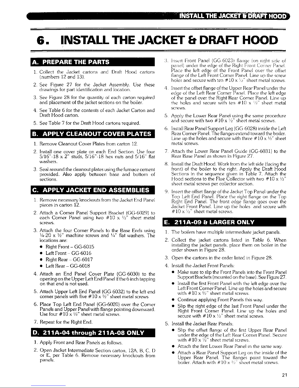
6. INSTALL THE JACKET 8 DRAFT HOOD
1. Collect the Jacket cartons and Draft Hood cartons
(numbers 12 and 13).
2. See Figure 27 for the Jacket Assembly. Use these
drawings for part identification and location.
3. See Figure 28 for the quantity of each carton required
and placement of the jacket sections on the boiler.
4. See Table 6 for the contents of each Jacket Carton and
Draft Hood carton.
5. See Table 7 for the Draft Hood cartons required.
i. Remove Cleanout Cover Plates from carton 12.
2. Install one cover plate on each End Section. Use four
5/16"-18 x 2" studs, 5/16"-18 hex nuts and 5/16" fiat
washers.
3. Seal around the cleanout plates using the furnace cement
provided. Also apply between base and bottom of
sections.
I. Remove necessary knockouts from the Jacket End Panel
pieces in carton 12.
2. Attach a Corner Panel Support Bracket (GG 6029) to
each Corner Panel using two #10 x Vi' sheet metal
screws,
3.
4.
5.
6.
7.
8.
9.
3. Attach the four Corner Panels to the Base Ends using i.
I/4-20 x V/' machine screws and V4" fiat washers. The
locations are: 2.
• Right Front- GG-6015
• Left Front GG+6016
• Right Rear GG-6017 3
• Left Rear GG-6018 4.
4. Attach an End Panel Cover Plate (GG 6030) to the
opening on the Upper Left End Panel ifthe 6 inch tapping
on that end is not used.
5. Attach Upper Left End Panel (GG 6032) to the left end
corner panels with five #10 x V/' sheet metal screws
6. Place Top Left End Panel (GG-6020) over the Corner
Panels and Upper Panel with flange pointing downward.
Use four #i0 x _/2"sheet metal screws.
7. Repeat for the Right End.
I. Apply Front and Rear Panels as follows.
2. Open Jacket Intermediate Section carton. 12A, B, C, D
or E, per Table 6. Remove necessary knockouts from
panels.
Inselt Front Panel (GG 60231 flange (on light side of
panet) under the edge of the Right Front Corner Panel.
Place the left edge of the Front Panel over the offset
flange of the Left Front Corner Panel. Line up the screw
holes and secure with ten #10 x _,z'"sheet metal screws.
Insert the offset flange of the Upper Rear Panel under the
edge of the Left Rear Corner Panel. Place the left edge
of the panel over the Right Rear Corner Panel. Line up
the holes and secure with ten #10 x _'>" sheet metal
screws.
Apply the Lower Rear Panel using the same procedure
and secure with two #10 x !/_" sheet metal screws.
Install Rear Panel Support Leg (GG 6028) inside the Left
Rear Corner Panel. The flanges extend toward the boiler.
Line up the holes and secure with three #10 x _//' sheet
metal screws.
Attach the Lower Rear Panel Guide (GG-6031} to the
Rear Base Panel as shown in Figure 27.
Install the Draft Hood. Work from the left side (facing the
front) of the boiler to the right. Apply the Draft Hood
Sections in the sequence given in Table 7. Attach the
Hood sections to the Flue Collector with two #10 x _//'
sheet metal screws per collector section.
Insert the offset flange of the Jacket Top Panel under the
Top Left End Panel. Place the right flange on the Top
Right End Panel. The front edge flange goes over the
Jacket Front Panel. Line up the holes and secure with
#10 x 9/' sheet metal screws.
The boilers have multiple intermediate jacket panels.
Collect the jacket cartons listed in Table 6. When
installing the jacket panels, place them on boiler in the
order shown in Figure 28.
Open the cartons in the order listed in Figure 28.
Install the Jacket Front Panels:
• Make sure to slip the Front Panels into the Front Panel
Support Brackets (mounted on the base). See Figure 27.
Install the first Front Panel with the left edge over the
Left Front Corner Panel. Line up the holes and secure
with #10 x Vi' sheet metal screws.
Continue applying Front Panels this way.
Slip the right edge of the last Front Panel under the
Right Front Corner Panel. Line up the holes and
secure with #10 x V_"sheet metal screws.
5. Install the Jacket Rear Panels:
• Slip the offset flange of the first Upper Rear Panel
under the edge of the Left Rear Corner Panel. Secure
with #I0 x Vi' sheet metal screws
• Attach the first Lower Rear Panel inthe same way.
• Attach a Rear Panel Support Leg on the inside of the
Upper Rear Panel. The flanges point toward the
boiler. Attach with #10 x _ sheet metal screws.
21
Page 25

• InstallaPanelSupportAngleontheinsidetopofthe 5.
UpperRearPanel(SeeFigure27).Use#I0 x _/"
sheetmetalscrews.
6.
• Install the remaining Upper Rear and Lower Rear
Panels in the same way.
• Place the edge of the last rear panel ow, i the Right
Rear Corner Panel.
6. Install the Draft Hood Sections:
1.
• Start from the left of the boiler (facing the front) Apply
the Draft Hood sections from left to right in the order 2.
given in Table 7. 3
• Use two #i0 x Vi' sheet metal screws for each Flue
Collector section.
I. Apply the jacket top panels working from left to right
(facing front of boiler). Place the panels from the cartons
in the sequence given in Figure 28.
2. Mount a Panel Support Angle (GG-6027) on the back
bottom edge of each Top Panel with the long flange
pointed down. Peal the insulation slightly away from the
back edge of the panel for better contact. Secure with one
#I0 x _" sheet metal screw.
3. Slide the left hand offset flange of the first Top Panel
under the Top Left End Panel, Place the front flange of
the Top Panel over the Front Panel. Line up the holes
and secure with #10 x Vi' sheetmetal screws.
4. Slide the left hand edge of each additional panel under
the panel to its left. Secure with #I0 x _zi' sheet metal
screws.
Apply the last Top Panel in the same way. Place its right
hand edge over the Top Right End Panel. Secure with
#i0 x Vi' sheet metal screws.
Check for loose or missing screws as you complete the
jacket assembly
4.
THIS APPLIES TO ALL BOILER SIZES.
The parts are packed in carton # 12.
Attach an End Panel Cover Plate to the opening in the
Lower End Panel (GG-6022) if the tapping in the boiler
is not being used. Secure with two #10 x V/' sheet metal
screws.
Apply a Lower End Panel to each end of the boiler.
securing to the Corner Panels with eight #i0 x _/z"sheet
metal screws Attach to the Upper End Panels with two
#10 x V./' sheet metal screws.
I. Mount Boiler Rating Plates, Agency Plates and Caution
Labels on the Upper Right End Jacket Panel.
2. Plates to be field applied are packed in Box Number 7.
3. Place these plates as shown in Figure 26.
4. Secure metal plates with #6 x V4" sheet metal screws.
Apply all adhesive-backed labels.
Figure 26: Location of Rating, Agency and Instruction Plates on Upper Right End Panel
22
Page 26

Top Panel (GG-6024) Right End Panel
(GG-6019)
Top Left End Panel
(GG-6020)
Upper Left End
Panel (GG-6032
Lower End
Panel
(GG-6022)
i-
I_ Front Panel
(GG-6023)
E.
Right Front
Corner Panel
(GG-6015)
Corner Panel
Support Bracket
(GG-6029)
Cleanout Cover
Plate Assembly
(GG-60O4)
Draft Hood (GG-50Ol
Left End Corner
Panel (GG-6016)
-- Front Jacket Panel
Support Bracket
(GG-2069)
Top Panel (GG-6024)
Panel Support Angle
(GG-6027)
Right Rear
Corner Panel
(GG-6017)
Upper Rear Panel --
(GG-6025)
Lower Rear Panel Guida
(GG-6031)
Lower Rear Panel
(GG-6026)
Rear Panel Support Leg
(GG-6028)
End Panel Cover Plate
GG-6030
j-/
/- Left Rear
Corner Panel
(GG-6018)
Figure 27: Jacket Assembly
23
Page 27

• ' ,.::1 • '_._ oo_
Table 6: Jacket and Draft Hood Carton Contents - See Figure 27 for Placement of Jacket Sections
Ca_on No.
12
12A
Contents
' Cleanout Cover Plates
Jacket Corner Pane!, Right Front
Jack_'t Cumin Pan_'! Leit Front
Jacket Corner Panel. Right Rear
Jacket Corner Panel, Left Rear
Corn_i Pan_l Support Brackets
• Jacket Upper End Pane!. Left
Jacket Upper End Panel, Right
End Pane! Cover Plates
Jacket Lower End Pane!s
Sheet Mete! Screws
Machine Screws, Washers. Nuts
Jackefl l_ermediate Panel - Front 1
Jacket Intermediate Panel _
Jacket IntermP&ate Pane!- Upper Rear I
Jacket Intermediate Panel Lower Rear
Panel Suppor_ _Angle
Rear Panel Sup_o_ l_fl
Lower Rear Panel Guide
Sheet Metal Screws
Sub-Assembly No. Part Number Quantity
GG-6004 1_ I
GG-6015 I
G(J 6016 l
GG-6017 r 1
[ ....
GG-6018 _ 1 I
GG 6033 GG-6029 4
GG 603Z 1
_21 _ i -
GFG 6-6o3o 14-............z
, GG 6022 2
.... GG-6023GG_6024 A]il .......
GG 6025 1
GG-6034 GG-6026 I
GG-6027 [ 2
GG-6028 1 |
GG 6031 1
23
...... J_acket Intermediate Panel - Fron-( ...... 0G-6023-I [ -i ...........
Jacket Intermediate Panel-To_ _ _ 1
Jacket [ntermedlate Panel - Upper Rein GG-6025 I I _I-- ....
12B Jacket Intermediate Panel Lower Rear GG-6026-I 1
Panel Suppor_ Angle GG-6034-1 _ GG-6027 I 2
Rear Panel Support Leg G[GG-6028 _ I
Lower Rear Panel Guide _,o-6031 1
[ +
Sheet Metal Screws .... 23
Jacket Intermediate Panel - Front
Jacket Intermediate Panel - To_
Jacket Intermediate Panel - Upper Rear
Jacket Intermedmte Panel - Lower Rear
12C Panel Support Angle GG-6034-2
Lower Rear Panel Grade
Sheet Metal Screws
Jacket Intermediate Panel - Front
Jacket Intermediate Panel - Top
Jacket Intermediate Panel - Upper Rear
Jacket Intermediate Panel Lower Rear
12D GG 6034 3
Panel Support An_te
Rear Panel Support
Lower Rear Panel Guide
Sheet Metal Screws
Jacket Intermediate Panel- Front
Jacket Intermediate Panel- Top
Jacket Intermediate Panel - Upper Rear
Jacket Intermediate Panel Lower Rear
Lower Rear Panel Guide
Sheet Metal Screws
Draft Hood Section
13
Sheet Metal Screw_
Draft Hood Section
13A ...... j She_ Met_ Scre_ ......
Draft Hood Section
13B
Sheet Metal Screw_
I Sheet Metal Screws
GG-6023-2 _ I
_2 I_ ___
GG 6025-2 i
GG-6026 2
GG-6027
GG-6028
GG-6031
GG-6023-3
GG-6024-3
GG-6025 3
GG-6026-3
GG_027
GG-6028
GG-6031
GG-60234
I
2
, 1
23
1
1
1
' 1
23
GG 6025-4 1
' 1
GG-6028
GG-6031
GG-5001
GG 5001
I
23
I
GG-5001-1
GG-5_I-I
GG-5001-2 1
..... ....
24
Page 28

Boiler
Model
Number
of Ca_ons
_m
1 3 5 7 9 11 13 15 17 19
21 23 25 27
2iiA-O4 1 r ] F I A
211_ 1 L_ _ B
2! 1A 06 1 C
211A-07 1 D
211A-08 E
211A-09 B
211A-10 1 1 B
211A-1! 15
25
29 31 33
35 37 39 41 43 45
45
A I
A' !
A
Figure 28: Jacket Assembly Sequence - Carton Numbers and Locations
_J7
Page 29

Table 7: Draft Hood Section Placement (from Left to Right Facing Front of Boiler)
ModeIB°ilerli Position , Position2 Position3 Position4 Position5 Position6 Position7 Position8 Position9
211A 04 13
211A 05
=211A-06
[ 211A-07
! 2uA-os
L211A709 _ 13A
ii 211A-10 13C
!i 211A-!! 13C
i 211A-12 13A
, 211A 13 13A
211A-14 I 13C
211A-16 13C
13A
13A
I
; L
13
13A ,
13B "
13A 13
13A ! 13A
t
13B 13B l
13B 13C
13C 13C
211A-17 13B 13B 13B
211A-18
211A-19
211A-20 !
211A-211
211A-22
211A-23
13C
13B
13C
13C 13C
13C 13B
13C 13C
211A 24 13C 13C
211A-26 13C 13C
211A-27 13C 13C
211A-28 13C 13C
[
13B
i
13B 13B 13B
13C 13C 13B |
13C 13C 13B
13C 13C
13B 13B
13B 13B
13C 13B
13C 13C
13C 13C
13B 13B
13C 13B
i i
!-, i i
13B
13B
13B
13B
13C [
13B 13B I
13B 13B
211A-29
211A-30
211A-31
211A 32
211A-33
211A-34
211A45
13C 13C 13C
13C 13C 13C
13C 13C 13C
13C 13C 13C
13C 13C 13C
13C 13C 13C
13C 13C 13C
211A-38 I 13B
211A-39 13B
211A-40 13B
211A-41 13C
211A-42 13B
211A-43 13B
! 211A-44 13B
211A-45 13B
211A-36 : 13C 13C i
211A-37 13C i 13C
i
13B
13B
13C
13C
13B
13B
13B
13C
13C
13C
13B
13C
13C
13C
13B
13B
13C
13C
13C
13C
13C
13B 13B
13C 13C
13C 13C
13C 13C
13C i 13B
13B 13B
13c 13cL
13B 13B
13B
13B
13C
13C
13C 13C
13C 13C
13C 13C
13B
13B
13C
13B 13B
13C I 13C
13c j 13c
13C 13C
13B
lac
13C
13C 13C
13C 13C 13C
13B 13C 13C 13C 13C 13C
13C 13C 13C 13C 13C 13C
13C 13C 13C 13C13C 13C
13C 13C 13C 13C 13C 13C
I i3d i
i 211A46 I 13C 13C _ 13C [ 13C _ 13C I 13C _ 13C 7 13C
26
Page 30
7. CONNECT GAS PIPING
1 The Gas Control Train(s) supplied with this boiler:
s Has been factory assembled and tested for tightness
of joints,
• Mustbere-testedafterinstallationwithasoapsudstest
to assure it is still leak tight after assembly.
• Must be isolated from the gas supply piping during
testing of the supply piping.
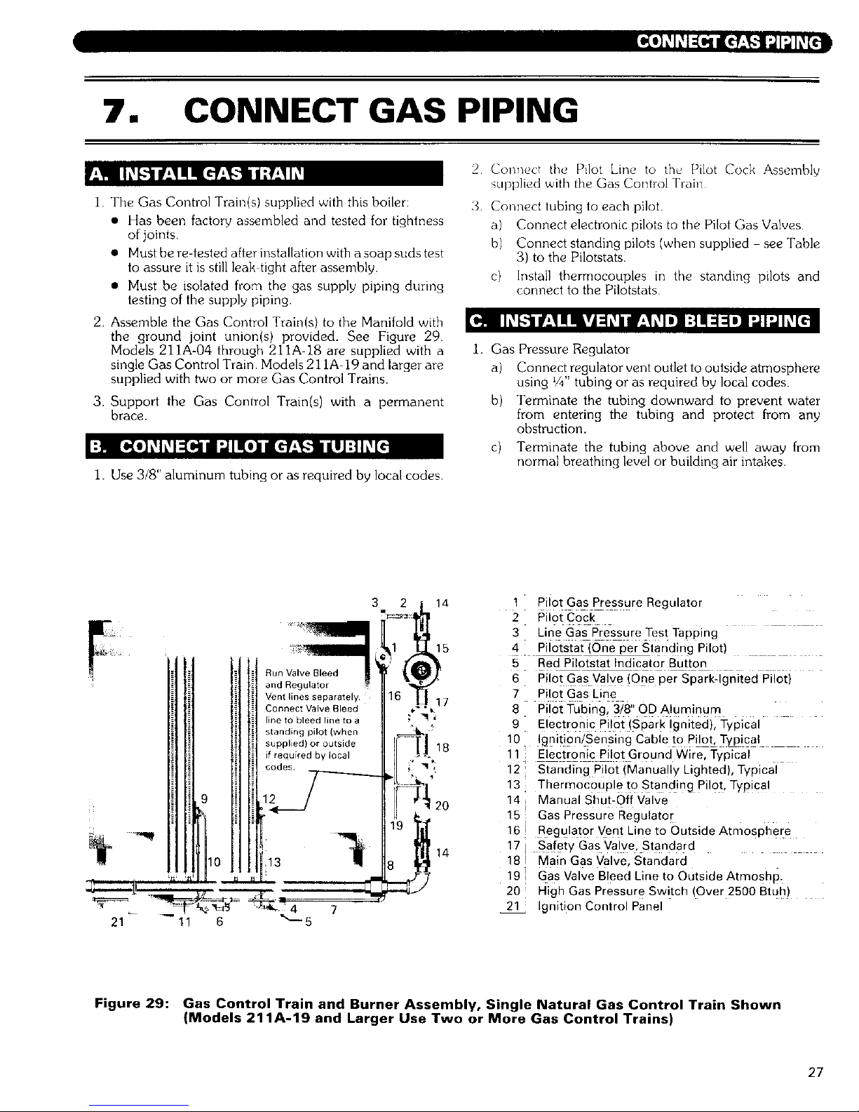
2. Assemble the Gas Control Train(s) to the Manifold with
the ground joint union(s) provided. See Figure 29
Models 211A-04 through 211A 18 are supplied with a
single Gas Control Train. Models 211A-19 and larger are
supplied with two or more Gas Control Trains.
3. Support the Gas Control Train(s) with a permanent
brace.
I. Use 3/8" aluminum tubing or as required by local codes
2 Connect the Pilot Line to the, Pilot Cock Assembly
supplied with the Gas Control Train
3 Connect tubing to each pilot
a) Connect electronic pilots to the Pilot Gas Valves.
b) Connect standing pilots (when supplied see Table
3) to the Pilotstats.
c) Install thermocouples in the standing pilots and
connect to the Pilotstats
1. Gas Pressure Regulator
a) Connect regulator vent outlet to outside atmosphere
using V4"tubing or as required by local codes.
b) Terminate the tubing downward to prevent water
from entering the tubing and protect from any
obstruction.
c) Terminate the tubing above and well away from
normal breathing level or building air intakes.
Vent lines separately.
Connect Valve Bleed
line to bleed line to a
standing pilot (when
supplied) or outside
if required by local
codes
g
21 11 6 _---5
3 2 14
_1 15
1 _14
8
1 Pilot Gas Pressure Regulator
2 Pilot Cock
3 Line Gas Pressure Test Tapping
4 Pilotstat (One per Standing Pilot)
5 Red Pilotstat Indicator Button
6 PiiotGas Valve (One per Spark:ignited Piioti
7 Pilot Gas Line
8 Pilot Tubing, 3/8" OD Aluminum
9 Electronic Pilot (Spark Ignited), Typical
10. lgnit!gn/Sensing Cable to Pilot, Typical
11 i Electronic Pilot Ground Wire, Typical
12 Standing Pilot (Manually Lighted), Typical
13 Thermocouple to Standing Pilot, Typical
14 Manual Shut-Off Valve
15 Gas Pressure Regulator
16 Regulator Vent Line to Outside Atmosphere
17 Safety Gas Valve, Standard
18 Main Gas Valve, Standard
19 Gas Valve Bleed Line to Outside Atmosh #.
20 High Gas Pressure Switch (Over 2500 Btuh)
21 Ignition Control Panel
Figure 29: Gas Control Train and Burner Assembly, Single Natural Gas Control Train Shown
(Models 211A-19 and Larger Use Two or More Gas Control Trains)
27
Page 31
2 Diaphragm Gas Valves
a) Pipe diaphragm gas valve bleed lines to outside
atmosphere unless the boiler is equipped with a
standing pilot. On standing pilot boilers, pipe the
valve bleed lines to the bleed piping pre-installed to
the pilot burner
b) Use _'F tubing or as required by local codes Always
pipe the bleed lines separate from the regulator vent
lines
c)
When piping bleed lines to outside, terminate the
tubing downward to prevent water from entering the
tubing, and protect the tubing teimination from any
obstruction. Terminate the tubing above and wel}
away from normal breathing level or building air
intakes
To Gas Supply -_
Service Valve -_
Ground Joint Uni_i_
J
To Boiler Gas Control Train "n_
Sediment Trap _'_JT; !
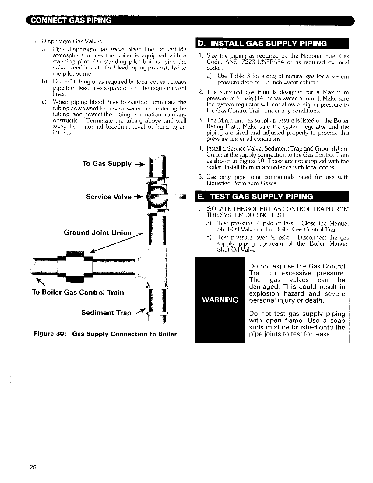
Figure 30: Gas Supply Connection to Boiler
1,
2.
3.
4,
.
Size the piping as required by the National Fuel Gas
Code. ANSI Z223 1,_FPA54 or as required by local
codes
a) Use Table {4 for sizing of natural gas for a system
pressure drop of 0 3 inch water column
The standard gas train is designed for a Maximum
pressure of _/2psig (14 inches water column) Make sure
the system regulator will not allow a higher pressure to
the Gas Control Train under any conditions
The Minimum gas supply pressure is listed on the Boiler
Rating Plate. Make sure the system regulator and the
piping are sized and adjusted properly to provide this
pressure under all conditions.
Install a Service Valve. Sediment Trap and Ground Joint
Union at the supply connection to the Gas Control Train
as shown in Figure 30. These are not supplied with the
boiler. Install them in accordance with local codes.
Use only pipe joint compounds rated for use with
Liquefied Petroleum Gases.
1. ISOLATE THE BOILER GAS CONTROL TRAIN FROM
THE SYSTEM DURING TEST:
a) Test pressure _/bpsig or less - Close the Manual
Shut-Off Valve on the Boiler Gas Control Train
b) Test pressure over _/5psig Disconnect the gas
supply piping upstream of the Boiler Manual
Shut-Off Valve
Do not expose the Gas Control
Train to excessive pressure.
The gas valves can be
damaged. This could result in
explosion hazard and severe
personal injury or death.
Do not test gas supply piping
with open flame. Use a soap
suds mixture brushed onto the
pipe joints to test for leaks.
28
Page 32

Table 8: Capacity of Gas Supply Pipe in Cubic Feet Per Hour of Natural Gas for 0.3 inch Drop
Pipe Length 1 V4"
(Feet) Pipe
1 1/2"
Pipe
2_9
Pipe
21/2" 3" 4" 6"
Pipe Pipe Pipe Pipe
J 1
1(} 1050 1600 3050 4800 8500 17500 44000
_o _o ' ,,oo _!00 _3o0 5oo_I i_oooi[3,o0o
l
30 590 890 1650 2700 4700 9700 I
25000
4o 500 ! 145o1 I 4,0o 22oo0
50 440 670 1270 2000 3600 __1 7400 / 20000
T ........... t- [ --
60 , 4;0 ;]; _ 1150 _ 1850 J. 32;0 + 6800
1050 1700 3000 i 6200
[
490 930 1500 2600 5400
460 ' 870 1400 2500 i 5100
i
380 710 1130 2000 4i00
70 350 560
90 I 320
100 305
150 250
18000
17000
15000
14000 "
11500 ,:
............... J
Above ratings based on natural gas with specific gravity of 0.60 allowing pressure drop of 0.3 inches. No allowance is
needed for pipe fittings. Use the following multipliers on above capacities for specific gravity other than 0.60:
--==SpecificGra;iU=_ 0.50 i_:55 i ] ;:6; ] 0.65
Multiply Capacity by: 110 1.04
....... i =
1.00 .962
0.70
.926
I
29
Page 33

8. INSTALL CONTROLS AND TRIM
1 Pipe the Pop Salety Valve(s) in the 3"" tappings located 1
on the right or left end sections Make sure the relief valve
sizing meets local code requirements• 2.
Pipe the discharge of the Safety
Valve away from any traffic area,
preferably to a floor drain. This
ts necessary to prevent injury
should the valve discharge.
Pipe the discharge full size of
valve outlet.
1. [nstall a I V2" full port ball valve in each of the tappings
provided at the lower back of the end sections. See Figure
31
2. Pipe the valve discharge to a floor drain if available or
apply a nipple and cap to close off when not in use.
Install Boiler Pop Safety Relief
Valve(s) in 3" End Section Tapping(s)
Pipe Safety Valve Discharge
to safe location, preferably to
a floor drain
2" Skim
Connection
12) 1 W' Blowdown Valves
ip off
Figure 31: Blowdown Valve Piping
.
4.
5.
6.
7.
Mount the float type Low Water Cutout and Gauge Glass
in the tappings provided in the front of either end section.
Do not apply piping which would raise or lower the
location of the cutout relative to the tappmgs in the boiler.
Raising the water level over the design height will cause
water carryover to the system.
For correct location of typical low water cutout!feeder or
low water cutout/pump control, see Figures 33 through
36.
Mount the probe type low water cutout supplied with the
boiler. The end sections have %" tappings in the front
for mounting the probe low water cutout auxiliary
control. See Figure 13.
a) The standard probe control is either the Hydrolevel
Model 650P or McDonnell & Miller Model PS850.
These controls are automatic reset type.
b) When a manual reset control is required, the boiler
can be supplied with either the Hydrolevel Model
550P or the McDonnell & Miller Model PS850M.
Provide each float low water cutout with a blowdown
valve. Pipe the blowdown away from traffic to a floor
drain if available• The blowdown valve is required for
proper maintenance of the control.
Maintain a height of 40 Vi' from boiler foundation to the
normal water level.
When using Multiple Float Type Controls: Always pipe
the controls off of the same tappings to the boiler. Do not
mount on different ends of the boiler or in different
tappings. This can cause erratic operation and nuisance
problems with the controls.
I.
Pipe the Steam Pressure Gauge and Boiler Lim:,t and
Operating Pressure Controls as shown in Figure 32.
Connect the control assembly to the Vi' tapping on the
right end of the boiler.
Make sure that the gas ignition
system components, electrical
controls, junction boxes and
electrical panels are protected
from water (dripping, spraying,
rain, etc.) during boiler
operation and service (trap
servicing, control replacements
or other).
30
Page 34

D
C
F
S
C
D
Option 1
S
Option 2
A
B
C
D
E
F
3/4" X 3/4" X 1/4" Reducing Tee
3/4" Cross
3/4" Plug
3/4" x 1/2" Hex Bushing
3/4" x 1/4" Hex Bushing
1/4" x 3" Brass Nipple
S
\C
C
A
G
H
J
K
P
S
3/4" x 3" Nipple
3/4" x 4" Nipple
3/4" x 5" Nipple
1/2" x 6" Brass Nipple
Steam Gauge
Pressuretrols
(Right Hand Shown, Left Hand Opposite)
(NOTE: Some local codes may require larger piping)
Figure 32: Pressure Control Piping (Fittings Included with Boiler)
31
Page 35

• t_lli_ -*_1_1JflhV_l
Burner Cut-Off Level --
1/2'_
Conduit
Connection
i
........... l.-|
8 1/2"
Water Line
t
4"
!
1 3/4" ]_
_r
f ......... 2"-
5"
J
Figure 33: Standard Float Type Control, Model 67PE2
Figure 34: Optional Feeder/Low Water Cutout, Model 47-2 - Used Only on Models 211A-04
through 211A-08 - Capacity Not Adequate for Larger Boilers
32
Page 36

4
12"
_4
E
C
Burner Cutoff Level
(Mark on Casting)
Normal Water Line :
/
12 5/16"
J
C
Boiler Foundation
D
A
C
B
H
Install 1" Blowoff Valve
SUGGESTED FII-rlNGS LIST
A 1" Cross F 1" x 6" Nipple
B 1" Ground Joint Union G 1" x 8" Nipple
C 1" Plug H 1" x 8 1/4" Nipple
D 1" x 2" Nipple J 1" x 14" Nipple
E 1" x 3" Nipple K 3" x 1" Bushing
The connected fittings shown on this drawing are
to be supplied by the installer,
Figure 35: Optional Float Type Pump Control/Low Water Cutout, Model 157
33
Page 37

C
D
H
B
C
G
.i_ C
A H F
J
_' 4 1/8" -_ 8 1/8"
Normal Water Line
2 n
-. -
! •
3/4"
40 1/2"
12 7/8"
E
i
J
I' Boiler Foundation
r-
Control Center Line
Feeder Closing Level
(Mark on Casting)
Burner Cut4Off Level is 1 1/2" Below
Center Line on 51-2 and 51-S-2 Controls
(2 3/4" Below Normal Water Line)
D D
l, B
install 1" Biowoff Valve
APPLICATION OF 51 FEEDERS
Models 211A-04 thru 211A-23
One 51-2 Feeder/Cutoff
Models 211A-24 thru 211A-39
One 51-S-2 Feeder/Cutoff
Models 211A-40 and Larger
Two 51-2 Feeder/Cutoffs
Consult Factory for proper application of feeders.
Always use a pump control and boiler feed system
instead when possible.
SUGGESTED FII-rlNGS LIST
A
B
C
D
E
F
G
H
J
1" Cross
1" Ground Joint Union
1" Plug
1" x 3" Nipple
1" x 5 1/2" Nipple
1" x 8" Nipple
1" x 8 1/4" Nipple
1" x 19 1/2" Nipple
3" x 1" Bushing
The connected fittings shown on this drawing are
to be supplied by the installer.
Figure 36: Optional Feeder/Low Water Cutout, Type 51-2
34
Page 38

9. WIRE THE BOILER
1 All wiring must be done in accordance with local codes. 1
the National Electrical Code and other controlling
agencies or governing bodies 2.
The boiler must be electrically
grounded in accordance with
the requirements of the
authority having jurisdiction,
or in the absence of such
requirements, with the
current edition of the National
Electrical Code, ANSI/NFPA
Number 70.
2. Use #14 gauge or heavier wire for supply wiring• Protect
the circuit with a fused disconnect switch (by others) and
a grounded neutral.
3. Mount an dectricaljunction box on the boiler Front Panel
for connection of supply wiring and distribution to the
boiler controls. See Figure 37.
Mount th_ conlrol transforma on the ]umlion box as
shown in Figure 37
Mount a iunction box near each Gas Control Train for
connection of conduit and wiring distribution to the gas
train components
2.
3.
4.
Wire the boiler according to the wiring diagram supplied
with the boi}er (in the Control Envelope). Figure 37 is a
typical layout of the components on the boiler. Figures
38 and 39 are examples of standard wiring systems. Use
these drawings for general reference only.
Low Energy Safety Control wiring must follow the
contour of the boiler. Some local codes may require that
all wiring, even low voltage, be routed in conduit.
Install all line voltage wiring in conduit•
Do not install single pole switches, including safety
controls, in a grounded line.
Probe Type
Low Water Cutout
Float Type
Low Water Cutout
- u
• •.•/ •
. "x
/-/ x_
//
120-V/60hz Power
Transformer, 120v/24v
Operating and Limit
Pressure Controls
Gas Pressure Regulator
Control Box
Main Gas Valves
Pilot Gas Valve
High Gas Pressure
Switch (when req'd)
Figure 37: Typical Control Layout and Wiring
35
Page 39

120v/60hz (_)
Neutral
120 V'dO hz
HOT
/
High Gas Pressure |
Switch (H C645B)
(Modeis211A 13 = :_1_i I
Through 211A 18)
Flame Rollout
Switch _l_
(When Req'd)
I
Float Type
LowWater C_ \
Cutout _ i
Spill Switch
(When Req'd) _ ,_
Operating Pressure r_ '
Control L/ _ J
!
1
Additional
Limit Switches
(When Req'd)
Transformer
120V,24V
1OOva
gngion/Sensing
Lead
_ lectronic
Pilot
d Lead to Pilot Burner
(200° C Thermoplastic Onlyl
4-
,goitio°Contro,!:T
{HSBdf0M 1Otq i .__ _ =%_
Pilot Gas Valve
High Limit
Pf _ss[Jre Control
Probe Type Low Water
CtltolJt Hydrolevel
Model 650P Shown
L,!II] Valve Switching
Relay (H R8222A)
Low Voltage
_*_v. Main Gas Valve
Low Voltage
Safety Gas Valve
TYPICAL WIRING - HSP SYSTEM - SINGLE GAS CONTROL TRAIN, 24-VOLT GAS VALVES
120V/6Ohz [L2) 120 V/dO hz
Neutral HOT
@
High Gas Pressure i| Train 2 /Train 1
Switches Ooeper _ _(_ _ _
Gas Control Train ' _ _ Transformer
(H C645B) / L_ 120V/24V
Flame Rotlout _ Additi°n, at/h _ I 4Ova
Switch _ Limit Switches ._, " J
(When Req'd)
/
(When Req'd}
Float Type |_
Low Water O-- i Ignition Control
Cutout _ (H $8610M-1011)
Spill Switch
(When Req'd)
Operating Pressure _ _ ' r l /_,_
Control , _'--
Pilot Gas Valve
High Limit
Pressure Control
Probe Type Low Water
Cutout - Hydroleve[
Model 650P Shown
r_-> :_ - Switching
• _ Relay !_ Transformer
_ (H R8222A} -- 120V/24v
I _ _ 1OOva
nition/Sensing i _i
Lead
_ Electronic
iiP,,ot ,,
/ A, U !
/--Ground Lead to Pilot Burner
(2go r' C Thermoplastic Only) _'_'_
Low Voltage
Main Gas
Valves
Low Voltage
Safety Gas
Valves
TYPICAL WIRING - HSP SYSTEM - TWO GAS CONTROL TRAINS, 24-VOLT GAS VALVES
120-V Hot Wires I -- 24 V Hot Wires I All wiring must comply with applicable codes, ordinances
..... 120 V Neutral Wires[ 24-V Neutral Wires ._ and regulations. If any of the original wire must be replaced,
All wiring 80" C Thermoplastic except as noted | it must be replaced with wire as shown or its equivalent.
Figure 38: Typical Wiring - Standard Controls - Low Voltage Gas Valves
36
Page 40

120V 60hz [L2) 120 V'60 hz
Neutral HOT
/
Hi!tb Gas Pressure _|
(ModeisSWitch(H21C645B)IA13 ' ':_} {I'_I) "_
Tbrough 211A 18) / Adddional
Flame Rollout Limit Switches
Switch _ _ (When Req'd)
(When Req'd)
Ii
Float Type
Low Water O_ \
Cutout _ Ignition Control
/ (HS8610M 1011)
Spill Switch
{When Req'd) _
ControIOperatingPressure [_ 'i ' i
_ Pilot Gas Valve
(_
High LimO
Pressure Control
Transformer
120V/24V
40 va
I
Probe Type Low Water
Cutout Hydrolevel
Model 650P Shown
Ignition/Sensin 0
_ Electronic
liP,o,
, €-7 II<Spar 'gnged>
/ A.V____J
Ground Lead to Pilot Burner
Valve Switching
Relay (H R8222A)
120 V Main
Gas Valve
120-V Safety
Gas Valve
(200 C Thermoplastic Only)
TYPICAL WIRING - HSP SYSTEM - SINGLE GAS CONTROL TRAIN, 120-VOLT GAS VALVES
120V_60hz L{_ 120 V/60 hz
Neutral _ HOT
/ /
/ Train 2 / Train t
High
Gas Pressure
J
!
Switches One per _ _ fl _,_
GasControltrain _Rj @ @ (_ (_ _W)
; d 7'snawL ,..
Swl ch J-_ > _e), I
(When Req'd) O-- _ (When Req'd)
Float Type
Low Water
Cutout _ Ignition Control
1
{H $8610M-1011
Spill Switch
(When Req'd) -F_ ,'_
i
Operating Pressure [_ _"
Control ! : _--
t
Pitot Gas Valve
_--_"_ High Limit
_t" Pressure Control
Transformer Probe Type Low Water
120V/24V Cutout - Hydrolevel
40 va Model 650P Shown
t
I_= z _
Igndion/Sensing
Lead , [
_ Pilot
{Spark Ignited)
fG:o Und Lead to PiIotBurner ii, t _
(20u ° C Thermoplastic Only)
Valve Switching
Relay (H R8222A)
"_ 120-V Main
Gas Valves
_ 120-V Safety
i Gas Valves
i i I Additional
i Gas Valves
: Req'd on
Train 2 21 IA-36
211A 37
TYPICAL WIRING - HSP SYSTEM - TWO GAS CONTROL TRAINS, 120-VOLT GAS VALVES
120-V Hot Wires --24-V Hot Wires All wiring must comply with applicable codes, ordinances
120 V Neutral Wires 24-V Neutral Wires and regulations. If any of the original wire must be replaced,
All wiring 80 ° C Thermoplastic except as noted it must be replaced with wire as shown or its equivalent.
Figure 39: Typical Wiring - Standard Controls - 120-Volt Gas Valves
37
Page 41

10. STARTING THE BOILER
l) Turn down the Operatm 9 Pn_ssure Control to stop
fl_e call for heat.
I Water and Steam Piping
a) The Boiler must have been hydrostatically tested.
b) Check the attached piping for joint tightness
c) Continue monitoring as you proceed through start
up.
2 Gas Piping
a) Make sure the gas system piping and the connections
to the boiler Gas Control Train(s) have been leak
tested.
b) After the boiler is in operation, check the tightness of
all joints in the boiler gas piping with a soap suds
solution.
c) Purge the gas piping of all air up to the boiler Gas
Control Train.
l Fill the boiler to the normal water line
a) Gravity Systems and Pumped Return with
Condensate Units Fill to 40 I/2" above the boiler
foundation (center of gauge glass).
b) Pumped Return with Boiler Feed Unit Fill the boiler
using the boiler feed unit. Fill level will depend on
the control being used. but should be 40 i/2" above
the boiler foundation (iust below center of gauge
glass) when the pump stops
i. Before starting the boiler, study the Lighting Instructions
supplied with the boiler.
5.
6.
7.
g) Wait b0 seconds to allow the control to reset before
proceeding with the next step
Light Manual Pilots
a) Follow the procedure in the Lighting Instructions to
manually light any standing pilots.
Electronic Spark-lgnited Pilot Ignition Check
a) Turn up the Operating Pressure Control fora callforheat.
b) The electronic spark-ignited pilot(s) should ignite.
c) Turn down the Operating Pressure Control to stop
the call for heat.
d) The spark-ignited pilot(s) should shut off.
Check Main Burner Ignition
a) With the Operating Pressure Control turned down,
open the main gas shut-off valve(s).
b) Turn up the Operating Pressure Control for a call for
heat.
c) The electronic spark-ignited pilot(s) should ignite.
d) The main gas valves will then open and the main
burners should ignite.
e) Turn down the Operating Pressure Control to stop
the call for heat.
f) The electronic spark ignited pilot(s) and main
burners should shut off.
I. Shut off all electrical power to the boiler.
2. Close Main and Pilot 9as shut off valves. Wait for five (5)
minutes.
3. Set the Operating and Limit Pressure Controls to
minimum setting so they will not call for heat.
4. Perform Pilot Check:
a) Turn main electric disconnect switch to the "ON"
position.
b) Turn up the settings on the Operating and Limit
Pressure Controls so they will call for heat.
c) Check for a continuous spark at the electronic
spark ignited pilot(s)
d) Electronic spark-ignit_d pilot systems The control
will spark for 15 sc_conds Ittial tot ignition), then shut
down for a 5 to G minute wait period before
attempting anoth_r ignition
e) E]ectronicstandingpilotsystems Within15seconds
the control will click, indicating a safety lockout.
1. Remove the pressure test plug at the Main gas shut-off
valve. Attach a U-tube manometer.
2. Restart the boiler by turning up the Operating Pressure
Control for a call for heat.
3.
4.
Leak test all gas train joints with a soap suds solution.
Check the gas pressure at the entrance to the Gas Control
train.
a) The pressure reading underflow should be between
7 and 14 inches water column (5 inches minimum
ifgas train is sized for lower gas pressure).
b) If the pressure to the Gas Control Train exceeds 14
inches under any conditions, the system must be
provided with a lock-up type gas pressure regulator
to provide 14 inches maximum.
5. Check the Manifold gas pressure.
a) Remove the 1/8" pipe plug from the manifold gas
pressure tapping.
b) Attach a U-tube manometer.
c) Adjust the Main Gas Pressure Regulator to obtain
3 5 inches water column on Natural Gas or 10 inches
water column on Propane (LP) Gas.
d) NOTE: If the pressure is adjusted to set the
nameplate input to the boiler, do not set it more than
03 inches plus or minus from the specified settings.
38
Page 42

1] mole adjustment to the rate is needed it nlust be
done by changing the, burner gas ()rifices
The Minimum input rak, listed on tl_e nameplate
dpplies to boilers wifll staged fidng rate. Tbis
minimum rate is not adjustable It is controlled by an
odlk _, in the gas ham
b Ch_ck the burner input by reading lhe gas meter
a) Each of the burners is rated at ]05,000 Btuihr for
Natural Gas with a 060 specific gravity
b) Each of the burners is rated at 102,500 Btu/hr for
Propane (LP) Gas with a [ 56 specific gravity.
c) Determine the input by multiplying "F" Meter
Reading (Cubic Feet of Gas) times "'H" - Heating
Value of Gas (Btu per Cubic Foot) times 3600. Divide
by "T" - the time in seconds at the meter reading.
F x H x 3600
Rate, Btu/Hr -
T
d) Note: If the meter is not automatically corrected for
temperature and pressure, the meter reading must
be corrected to actual conditions during the rate test.
7. Adjustment of Primary Air
a) A bag of air adjustment screws is provided with the
boiler, attached to one of the burners with pilot
bracket.
b) Primary air adjustment is not normally required.
c) If primary air adjustment is needed, insert the
self-tapping screws into the holes located on the top
front of the burners.
d) Turn the screws in all the way until yellow flame tips
appear. Turn the screws back out until the yellow tips
disappear.
]. Limit and Operating Pressure Controls
boiler wateL producing an unstable water line and water
carryover to the system.
Cleaning the boiler requires the
use of very hot water and
corrosive chemicals. Use care
when handling to prevent injury.
3.
4.
5,
6.
7.
The piping for a skim valve must be done as shown in
Section 5, "Pipe the Boiler", of this manual, with the skim
valve mounted off of one of the end riser connections
Connect a 2 inch drain line off of the skim valve, run to
a point of safe discharge.
Close all valves to the system. Provide a means of
continuous fresh water to the boiler for the cleaning
process.
Open the skim valve. Fill the boiler until water begins to
flow out the valve.
Use common washing soda (such as Arm and Hammer
Super Washing Soda). Mix the soda with water in a 10
quart pail and pour into the boiler through the safety valve
tapping. Use a proportion of one (I) pound of washing
soda for each 800 square feet EDR net boiler rating.
Do not leave the boiler
unattended while firing.
Take great care not to allow
the water level to drop below
the bottom of the gauge glass
or to allow fresh water make
up to flow in too fast, This will
avoid the possibility of causing
the boiler sections to fracture.
a) Lower the setting of each control until the burners
shut down.
2 Low Water Cutouts
a) Lower the water level in the boiler to below the
control cutout level. The burners should shut down.
3. Main Burner Shut-Off Valve(s)
a) Close Main Burner Shut-Off Valve(s).
b) The burners should shut down.
4. Check all controls to make sure they function correctly.
5. After all controls have been proven, set the Operating and
Limit Pressure ConlTols to the pressures desired.
I Clean the boiler as described below no later than one
week after the initial start-up. Cleaning will be more
effective if the boiler operates a day or two to loosen
sediment and impurities in the system.
2 The boiler must be cleaned to remove any accumulation
of oil, grease, sludge, etc. that may be in the system.
These substances can cause foaming and surging of the
8.
9.
10.
11.
12.
13.
14.
t5.
Turn burners on and allow the boiler water to heat up to
just below steaming (180 to 200 OF), Cycle the burners
to maintain temperature during skimming. Do not allow
the boiler to steam. Steaming mixes up the contaminants
in the water instead of floating them at the surface.
Open the make-up water valve to continuously feed
water to the boiler. Allow water to flow out of the skim
tapping.
Continue skimming the boiler until the water flowing
from the skim tapping flows clear. This will take some
time, possibly several hours for a dirty system.
After skimming is complete, close the skim valve and turn
off the boiler.
Close the make*up water valve and open the boiler
blowdown valves.
Drain the boiler completely. Then refill and drain again
one or two times to make sure all of the soda has been
washed out.
Restore piping to normal. Pipe a nipple and cap in the
skim valve.
Note: If the gauge glass becomes dirty again, this
indicates more contaminants have worked loose in the
system. Repeat the cleaning and skimming process as
needed to clean the system.
39
Page 43

1 1. LIGHTING INSTRUCTIONS - TYPICAL
1 These instructions apply only to typical standard control
systems (HSP System only). Use the Lighting Instructions
supplied with the boiler to be sure they apply to the actual
control system used
2. Set Operating Pressure-,Control to lowest position.
3. Open main line power disconnect switch to boiler
4. Close Main and Pilot gas shut-off valves.
5, Wait at least five (5) minutes.
6. With Main gas shut off valve(s) closed, open Pilot gas
shut-off valve.
7. Light standing (manual) pilots by depressing the red
indicator button on the Pilotstat. Manually light the pilot
and hold the red button long enough for the
thermocouple to heat up.
8. Open Main Gas shut-off valve.
9. Set Operating Pressure Conlrol to desired pressure setting.
10. Close main line power disconnect switch to boiler.
11. If all limit switches are closed, the spark pilot(s) will light,
main gas valves will open and main burners will light.
12. The burners will continue to fire until the Operating
Control is satisfied.
1. Open main line power clisconnect switch to boiler.
2. Close Main and Pilot gas shut off valves.
1.
2.
3.
4.
5.
6.
7.
If flame signal is lost at pilot, the ignition control will shut
off the main gas valves and start sparking within 0 8
seconds.
The control will continue to spark for 15 seconds.
If a flame is not sensed, the control will shut down the
pilot gas valve and wait 5 to 6 minutes.
It will then start sparking and open the pilot gas valve for
another 15-second ignition trial
The control will continue this sequence indefinitely.
Refer to Control Envelope supplied with the boiler for
the specific system used,
Should a flame failure occur, causing a shut down of the
main burners, turn off all electric power to the boiler and
close Main and Pilot manual shut-off valves. Call a
qualified service technician to inspect the boiler and
correct the problem.
3 2 14
15
17
f--_2_- PiiotGas Pressure Regulator
Pi/-o{ Cock
3 Line Gas Pressure Test Tapping
, 4 Pilotstat (One per Standing Pilot)
5 Red Pilotstat Indicator Button
6 Pilot Gas Valve (One per Spark-Ignited Pilot)
7 Pilot Gas Line
8 Pilot Tubin 9, 3/8" oD Aluminum
9 Electronic Pilot (Spark Ignited), Typical
10 1 !gn!ti°n/Sensin9 Cable to Pilot, Typical
11 Electronic Pilot Ground Wire, Typical
[ii - Standing PilOt (Manually Ei_hted); Typical
, 13 Thermoeouple to Standing Pilot, Typical
i 14 Manual Shut-Off Valve
,P'I5 Gas Pressure Regulator
1i 6 Fleguiator Vent Line to Outside Atmospheie
1/ Safety Gas Valve, standard
21i§ Main Gas Vaive, standard
16 GasValve Bleed Line to Outside Aimoshpl
20 High Gas Pressure Switch (Over 2500 Biuh)
Ignition Control Panel
Figure 40: Typical Gas Control Train and Base - Single Gas Control Train - Standard Controls
40
Page 44

12. OPERATION MAINTENANCE
Do not store or allow
combustible or flammable
materials near the boiler.
Substantial fire or explosion
hazard could result, causing
risk of personal injury, death
or property damage.
Do not use this boiler if any
part of it has been under
water. Immediately call a
qualified service technician
to inspect the boiler. Any part
of the control system, any
gas control or any burner or
gas component which has
been under water must be
replaced.
Should overheating occur or
the gas supply fail to shut off:
Shut off the gas supply at a
location external to the boiler.
Do not turn off or disconnect
the electrical supply to the
pump. Immediately call a
qualified service technician to
inspect the boiler for damage
and defective components.
1. Start up the boiler per the Lighting Instructions shipped
with the boiler.
2. Prove the correct operation of all controls on the boiler
as outlined below.
3. Check the operation of the ignition and flame proving
controls:
a)
Electronic Spark-lgnited Pilot System ($8610M
Control)
• With the boiler operating, close the Pilot manual
shut-off valve.
• The ignition control should close the main gas
valves within 1 second.
b)
• The control will spark and attempt to relight the
pilot burner.
• After 15 seconds, the control will shut down and
wait 5 to 6 minutes for another ignition trial.
• Open the Pilot manual shut-off valve and re-start
the boiler per the Lighting Instructions, (Standing
pilots will have to be manually re-lit per the
Lighting Instructions.)
Electronic Standing Pilot System
• With the boiler operating, close the Pilot manual
shut-off valve.
4.
5.
6.
7.
8,
I.
2.
3.
• The ignHio;i control should close the m,_lin gil>
valves wilhin _ seconds after tire pilot goe_ _tl_
• After i5 seconds, the control will lock out
• Open the Pilot manual gas shut-off valve and
re-start the boiler per the Lighting Instructions.
(Standing pilots will have to be manually re lit D>r
the Lighting Instructions.)
Check the manifold gas pressure and rise a soap suds
mixture to check the gas tightness of all gas ioints
Test the limit and operating controls to assure they are
operating correctly
Inspect and test all low water cutouts. (Float type conhols
must be flushed (blown down) weekly to remove any
sediment from the float chamber.)
Test the pop safety relief valve(s) using the procedure
given by the valve manufacturer on the valve tag
Visually inspect the burner and pilot flames.
a) See Figure 41
b) The flame inner cone should be about i _o"high and
should have a very sharp, blue color characteristic
c) Poor flame conditions can be caused by dirty
burners, obstructed orifices or incorrect gas pressure
Open main line power disconnect switch to boiler.
Close Main and Pilot gas shut-off valves.
To take boiler out of service if the boiler and system are
not to be used when temperatures are below freezing:
a) Drain the boiler and system completely and shut off
make-up water supply.
b) Open main line power disconnect switch to boiler.
Remove the fuses or secure the switch so that the
power cannot be turned on accidentally
c) Do not used ethylene glycol antifreeze in a steam
boiler or system.
d) Be certain that the boiler and system are refilled
before returning to service. Follow the Instructions in
this manual and the Lighting Instructions to operate.
Before servicing the boiler:
• Turn off all electrical power
to the boiler.
• Close the Gas Service Valve.
• Allowthe boiler to cool if
it has been operating.
• Label all wires prior to
disconnection when
servicing controls. Wiring
errors can cause improper
and dangerous operation.
Verify proper operation
after servicing.
41
Page 45

I. Beforethestartof each heating seasom inspect and
make all necessary adjustments to insure proper boiler
nperation Use the n]aintenance and inspection
procedures following
2. Inspect the Venting System
a) Check the chimney or vent to make sure it is clean
and flee from cracks or potential leaks.
b) All joints must be tight and sealed.
c) The vent connector must extend into, but not
beyond, the inside edge of the chimney or vent.
3. Inspect the Boiler Area
a) The boiler area must be clean and flee from
combustible materials, gasoline or any other
flammable liquids or vapors.
b) The combustion air openings and the area around
the boiler must be unobstructed.
4. Inspect boiler flueways and burners for cleanliness. If
cleaning is required, use the following procedure.
a) Turn off all electrical power to the boiler.
b) Remove top jacket panels, draft hood and flue collector
c) Remove side cleanout panels.
d) Brush the boiler tube spaces both horizontally
(through cleanout openings on ends) and vertically
(from top of boiler).
e) Replace the flue collector, draft hood. jacket and
cleanout panels using the procedures given in this
nlanual.
f) Remove the burners and brush the gas ports lightly
with a soft bristle brush.
5. Inspect the boiler base and insulation.
6. Inspect the boiler and piping for signs of leaks. Check to
see if there are signs of heavy make-up water addition to
the system.
7. When placing boiler into operation, follow Lighting
Instructions shipped with the boiler and the instructions
in this Chapter.
F, Test the operation of all limit conh his float conhols and
igntion components as described in Pa_t A. *Placing
Boiler in Operation", of this Chaptel
1. Inspect the burner and pilot flames as fol the annual
inspection.
2 Inspect the boiler and system for any signs of leakage or
excessive make-up water usage
3. Inspect and check the operation of the venting system.
1. Blow down the float type low water cutouts and test for
correct operation.
1. Inspect the boiler area to make sure the area is free from
combustible or flammable materials and that there are
no obstructions to the flow of air to the boiler or
combustion air openings to the room
2. Make sure there are no signs of abnormal operation, such
as overfilling or leakage.
Be very careful when adding
water to a hot boiler. Add
very slowly or, if possible,
allow the boiler to cool
naturally before adding
water.
If an excessive loss of water
occurs, check for a leak in the
piping and correct the
problem. Excessive make-up
water will cause corrosion
and damage to the boiler.
Figure 41: Pilot and Burner Flames
II
42
Page 46

113. TROUBLESHOOTING - SERVICE TIPS
PROBLEM POSSIBLE CAUSE SUGGESTED REMEDY
Defective Thermocouple Replace
Heavy Draft Blowing across Prlot
Plugged Pdot Onhce
Redirect Air Movement or Ehmlnate
ReD ace Ordlce
Pilot Outage
No Gas
_efective Pdo:s[al
Check Manual Pilot Valve
Check Main Gas Shut Off Valve
Check Manual Meter Valve
Consult Gas Company
Re_ ac_
Main Gas Valve Will Not Open
(Standard Spark-Ignited Pilot System)
Defective rgnt[ton Control
No Power
Defective Gas Valve
3efective Thermocouole
Low Water Level in Boiler
or System Causing Low Water Cutout to Function
3efective Pilotstat
Reolace
Check Power Source w th Meter
Check Fuses
RePlace
RePlace
Check for LeaKs
Check Feeder if SUD_ led
ReL_lacc
Defective Ignition Control Reotace
Check Switch Setting
_llgn Gas Pressure Switch Onen lif Prov ded Check Man fold Gas Pressure
Check Switch Setting
Low Gas Pressure Switch Ooen {if Provided)
Check Inlet Gas Pressure
No Power Check Power Source with Meter
Check Fuses
Defective Gas Valve RePlace
Main Gas Valve Will Not Open
(Electronic Standing Pilot Systeml
Relay Locked Out on Safel Check for Pilot Outage
Pilot Oul Relight Pilot
Ma_ have defective pilot valve or rela r
Defecnve ReJav Replace
.ow Water in Boiler Check for Leaks
or System Causing Low Water Cutout to Function Check Feeder if Supp.ea
Defective Pilotstat_s_ Re=31ace
Defective Thermocouc elsl Replace
Hign Gas Pressure Switch Ooen hf Provided Check Switch Setting
Check Manifold Gas Pressure
Low Gas Pressure Switch Open (if Provided Check Switch Setting
Check Inlet Gas Pressure
Air Ad ustment Screws Turned Too Far Adjust Screws Out
Low Gas Pressure in Manifold Adjust Main Gas Pressure Regulator
[nsufficient Air In ect_on or Check Line Pressure
Burner Ports Partial . Closed
ReoJace Burners or Clean Ports
Burner(s) Burning with Yellow Flame Rusl Dirt. Lint. etcl
Gas Spillage from
Draft Hood Relief Opening
nsufficient Air for Combustion
• k
Oversized Burner Onhce
High Gas Pressure in Manifold
nsufficient Draft - Chimnev Too Low
Insufficient Draft- Chimney Too Sma
Insufficient Draft Blockage inChimne, or vent
Insufficient Draft - Leaks in Chimne. or Vent
nsufficlent Draft Downdraft Caused h Chimney
Location with ResPect [o
Other Buildings, Roofs etc
Negative Pressure in Boiler Roorr
.Due to Exhaust Fan or Duct S,,stem]
Insufficient Combustton Air Openings
Check Size of Combustion Air Openings to Room
If Undersized Correct as Reauired
Check for Negative Pressure in Boiter Room
Install Correct Orifice
Adjust Main Gas Pressure Regulator
increase rlelgn[ or Add Induced Draft Fan
Replace Chimney or Add Induced Draft Fan
Remove BlocKage
Repair Chimney or Vent
nstall Chlmr ev CaD
Remove Exhaust Fan
or Isolate Fan From Boiler Roorr
ProvldeCorrectl Sized Combustion and
Vent lation Air Openings
43
Page 47

PROBLEM
POSSIBLE CAUSE
SUGGESTED REMEDY
Main Gas Valve Opens
But No Gas Flows
Manual Valve Closed at Gas Train
Manual Va ve Closed at Metel
Test Firing Valve Closec if Provided
aden Valve
_I tH] valve
Ooen Valve
S_gs i_l 5iedrll l_ i_lll(l c_r _1_31 _317o jR pll Ci;rrt,L:[ Pl I) rig CulldltlOtl
Water Hammer on Start-Up
Concentric reducers caum_ g condensate pooling
Dr iJ [r_ _ falIt!(J c ose(
_)rv -e[urns we[reel [lue [o new DC er water line
nlgner [Ran OlC113o er
Correct R pmg
Reuldcu Tral3 or Trap Element
Correct P 31ng or Install Feed System and Traps
Concentric reduce/s caus ng conaerlsaI_ DOOIIDg
No drio ne on [ne oacK Sicle of a DaCK-DltChed
mo[orlzecl valve
Clogged returlls d g_avqly s.sTem
Correct P ping
nstall Dr 3 Line and Trap
C ean or Re PqJe Return Lme(s)
Water Hammer During Mid-Cycle
Water Hammer on Shut-Down
Hammering in the Boiler
No Heat or Poor Heat Distribution in
the Building
System or Boiler Overfilling or Flooding
Incorrect near DoHer piping causing WeT steam to
system
Trao failed aden allowing s[ean3 to enter return_
{Radiator Hammer} Large raalator map be vented
too QUICKIV
_ong nip[ e at Har#ora LO00
Correct PIpmg per Manual
qeDlace TraD or Trap Element
Use Smaller Air Vent or Use Two Sma Vents in
Place of One Large Vent One Mounted Higher
than the Other
Rec ace with Close Nipple
Water leg or back SlODe in return line to receiver
tanK, causing water pocketing
Trae instal efJ at recewer [aRK Causing Hater
trapping irl return
Boiler feed Duma or conaensate pump feed rate
too fast. causmg spraymg rata equalizer
No drio on the nlet side ofaforwara oEtcnea
]qotorlzed valve
unlnsulateo steam OlD he, causlf_g excessive
;onclensate 3aas
Close n=DDI8 or7 Hdrtford too nlgr
unlnsulatea steam piping _ ooHer room but
System piping nsula[ec causlr ] vacuum
corlclltlOn on ShUt-down
Poor c_rculat on in the ha ler due to sludge
eccutl/ulat oil
Correct Piping
Remove Trac at Tank. Installing Drip Traps and
Radiator TraPs where Required
Throttle Flow Rate
Add Dr a Lme and Trap
Insulate Steam Pipes
ReD De 2" to 4" Be ow Normal Water Line
nsulate Steam Pipes
Clean and 8 owdown the Boiler
Rapid Cycling
Main vents not working Replace Main Vents, Repiping away from End of
, Lines if Needed
Drip traps failed closed Replace Traps or Trap Elements
r
i Radiator traps failed open, allowing pressur zat on
of the returns _ Replace Traps or Trap Elements
Water legs or back slope in return lines to
receiver tank, preventing air from venting out Correct Piping
receiver vent
1
Boiler pressure too high, causing air vents to lock
up or blowing water Ioopseals / Reduce Operating Pressure
New boiler water content smafler than old boiler Install Boiler Feed System with Receiver Tank
Large Enough for Condensate
Boiler water feed rate or pump rate too fast, /
causing water level to collapse (due to collapse of
s earn bubbles in boiler wa er) [
Foaming, priming or surging due to poor water
quality
water quality, causing foaming and surging I
Poor
Excessive Water Level Bounce Incorrect near-boiler piping, such as undersized
or incorrectly placed risers
I Boiler water rate or pump rate too fast
feed
Air vents or traps not ventrng air, preventing
steam from getting to radiation and pressurizing
the air pocket
Pressure differential on pressure control too close
Nuisance outages of water level control due to
boiler water level bounce
Reduce Feed Rate
Clean the Boiler
I
Clean the Boiler
!
Pipe per Manual
Reduce Feed Rate
Replace Vents or Traps
Adjust Control Differential
See Excessive Water Level Bounce Above
44
Page 48

14. BOILER RATINGS f:lrDIMENSIONS
Table: Boiler Rating Information
i[ Natural Gas Ratings
Boiler i ; IBR Net Ratings
Model i Input Output : T
= Steam i
Number MBH MBH i Steam Water
= MBH ; MBH
.[ , t
211A 04 630 804 1578 378 438
211A-05 660 672 2100 504 884
12iiA_06 1050 i 840 2625 I 630 ] 730
i?oo I ! 677
211A-08 1470 1176 3675 882 1028
211A 09 1680 1344 4229 1015 1169
Propane Gas (2500 Btu/Cu Ft)
[_ IBR Net Ratings
l
Steam _ r Sr_el_11 [ _a_ I Steam
Input Output Steam
P=pmg _ MBH | MBH r Piping
Factor Sq Ft ' Factor
L
EDR j
1333 615 492 1538 369 428 1.333
1333 820 656 2050 492 570 ] 1.333
1333[ 1025 8 0, 2663 _z13 ,383!
1.333 _ 1230 9843075 738 _ 8_ ]
1333 1435 1148 3588 861 | 998 1333
1324 1640 1312 4121 989 ! 1141 1327
! 211A=-!0 _.. 189n0 -_512 rT 4808 I-'!_4 11315 I ___3!.0 _1845 T 1476 ] 468811126 1283 1.312 ii
2!1A-! 1 _ 2100 11680 L 8_92 J !294 [ 1461 [ 1_298 _ 2050 I 1640 / 5258 | 126 _ 1426 [ _i_01]]]iI
211A 12 2310 1646 5971 1433 1607 1290 2255 1804 5821 1397 1669 1.291
211A-13 2520 2016 6521 1565 1753 1.288 2460 1968 6367 1528 17tl i 1.288
2940 t 2352 ! 7608 _ 22:: [_2___ 2132_ r _i,54 _ 1.2881
!i 211A-14 2730 2184 7067 _ 1696 I 18991.288 2665 6896 1655
:i_ 211A-15 i 1826 _ 2045 i 1. 2296 _ 7429 _ 1783 199711.288 I
211A 16 ; 3150 2520 8154 1957 2191 1.288 3075 2460 7958 1910 2139 . 1.288
211A-17 i 3360 2688 8696 2087 2337 1288 3280 i 2624 8488 2037 2282 1.288
211A_i8 _I 3570 2856 9738 ! " _ r _ I 11288_i
_ 37-- 211A-19 -_- 22172483 1.288 , 3486 2788 9021 . 2165 2424 i80 3024 _ 2348 + 2630 i 1.288 [ 36_£ + 29_ i 9550 j 2292 2587 ji_-_8
211A20 3990 3192 10825 2478 2776 1288 3895 3116 10078 2419 2710 1.288
211A21 4200 3360 10871 2509 2922 1288 4100 3280 10613 2547 2852 1.288
i 211A-22 _ 4410 T 3628 - 11413 i 2739 i 3068 [ 1.288 4305 ] 3444 ] 1ii42 2874 _- 2995 _288_
2!!A-23 ! 4620 i 3696 11858 [ 2870 _ 32!4 [ 1"288 45]O j 366_i-1167! 12801 _3137 [ ]28_
211A24 4836 3864 12500 3000 3360 1.288 4715 i 3772 12204 2929 : 3280 1.288
211A-25 - 5040 4032 ! 13042 _ 3130 3506 1.288 !_ 4920 ! 3936 12733 _ 3056 _ 3423 - 1.288
!_ 21iA:265250 i 4200113588 _ 328i 13852 'i 1:288 _ 5125 _4100 _ 13263 T_665 [ i:2881
:' 211_7 ...... 5460 "] _4368 _1_3391_ 379811.288 _ 633014264 / 13796 i 3311 3708 11.288 :!
)11A-28 - 5670 4536 4675 3822 " 3944 " 288 "= 5535 _4428 * 4325 ' "343-8 .... 385013850--+"i288 ]!
i 211A-29 5880 4704 15217 3652 4090 1.288 ' 5740 I 4592 14854 _ 35664319936_3993 1.288 i
[ 2iiA-3; -60;0 ] 4872" 15763_ 3783 _ 4257 i _.288 _694614766 F18388 13693 .28s
[ 211A-3i "63;; I "5040 16304 ia 3913 / 4383 / --i)88. L 6150 ,14920 J 15917 [........3820-- 72784278I 1:1_288- !/i
211A-32 6510 5208 16846 4043 4529 1288 L 6355 5084 16446 3947 442 288
=
p ff 4
11 211A33 6720 | 5376 17392 4174 4675 _ 1.288_ .!I ............6560 5248 i 16979 4075 4563 _ 1.288 ]
i 211A=34 6930 _ 5544 17933 4304 4821 1.288 6765 5412 17508 4202 4706 | 1.288 .
5712 1_79 4435 4967 1288 6970 5576 180381 4329 4849 1288
• t _ t _ i _ , l ._!211A-35 7140
216 20108 4s26r5405 128s
: 211A-40 8190
. 211A-41 8400
21iA-4218610
211,,43
211A 44 9030
211A 45 9240
21,A46
6552 21196 5087 5697 1.288
6720 21738 5217 5843 ! 1.288
6888 22283115348 _ 5990 } 11288 -=
7056 22825 ] 5478 6136 ..... _-288--:
7224 23371 5609 6282 1.288
7392 23913 5739 6428 1.288
Models 211A-38 through 211A-46
Are Certified for Natural Gas Only
7560[ 124458] 88701 6574[ 1.2681
45
Page 49

O3
B
(211A19 and Larger,Two Gas Control Trains))
B
1211A04thru 211A-18,Sngle Gas Control Train)
A
3% ° "AA- 3B - CC _ DD - EE " FF - GG "* HH - II M JJ . * 3_1_
O00O()O000
"1
T3 T8
4f ; •
, I! i t.
T3
331;" " D " E - c - G " _ " - J - K - L - rd .- N - O - P - -3_1;
Boiler Sectional Length
5 1/4"
C
32 5/8" 45 3/4"
TAPPING SCHEDULE
T1 End Supply Riser Taps,
6" each End Section
T2 Return Taps, 6" Each End
T3 3" Tap, Top, Each End
Section
T4 3/4"Tap, One Each End
Section
T5 1/2" Tap, Two Each End
Section
T6 1"Tap, One Each End
Section
T7 1"Tap, One Each End
Section
T8 Intermediate Supply
Riser Taps, 3", in Tapped
Intermediates
T9 3/4" Tap, One Each End
Section, For Probe LWCO
T10 1 1/2"Tap. Blowdown,
' Each End Section
Tll 3" Tap, Lower Rear,
Tapped Intermediate
Sections Only, Not Used
[] [] [] [] [1 [] [J [1 [J [J
2nd End Riser
211A-08 _ LargeT'_ _1
T5 T9
T6
4 '
T7 _ U ProbekowW terCutout
2nd Equlizer _ l
211A-16_Larger,,-_ Ti1-_. ; .... [ r
_T10
FRONT VIEW
; 27
81"
i li
-- !IT2
', i 71o,
22 ,1oo 4 ,ii711
.... 41" - .
Base End Width
Page 50

BOILER DIMENSIONAL DATA (All Dimensions In Inches)
: Flue _
Boiler Length_ Width ! Boiler Intermediate RiserCenter Lines- 3" Tappings- Used In Additionto Two EndRisers FlueConnectio, Ce,te( Lines
Model Dimenslo,s 'SBgton i .... _ . : _ _ [ _ Connections _ • =
No. A _B C ! Lengtih D iT E I F , G H I J / K ;_ L M N O : P ; AA : BB CC _DD ' £E FF G6 HH : JJ No Size _ _ = /
2 1A04 291/2 _ 39% 63 ! 213/, ! . - - _ ! - " -_ - ' - : - L - [16•/8 _L - : _ ± _ - _ 10% 1 12 12 12
211A 05 33_ 44 63 27_ - 13_':_ i9_ I ]2 12 _2
211A06 398_ 50% 65 • 33 ..... 16!/2 161_ / 14 14 14
56 / 631 38% i I L _ _ r _ T _ - _ - T - / i 2
1 I " 13_/4 19% i - 19/8 2 12 i5 15
211AI0 61 _ 73_._ 65 553/2 16vz 25_% 135 2 14 17 17
211AI1 67_ 89%4 65 611/_ 16_ 28% 15 2 14 1_ 16
211A-12 73'_ 66_/_ 63 663/. 133/.. 2212 19% 10_, _ 12 I_ I_
211A-13 783/.. 9W_ 63 ! 723/s [ - ] - [ _ - ] [ .... 113_/_ 2211222V_ - 13% 3 12 19 19
' _ ! ' 16'/225% 22V=! - 13%
211A-14 843/2 97Ve i 65 I 78 3 14 20 20
--_ 3 14 21 21
211A-15 90 102_._ 65 i 83%
211A-16 95 s 108_._ 65 69V4 16!# 26_ 261.a 16' 2 ;4 21 21
211A17 161 _ 114% 65 94V8 13_4 22'/= 22_.2 22_ 13_ 4 i_ 22 22
211A 18 1OZa 120_/e 65 100V; 53ve 47_b !6_h 25% 221/2 22_.'2 13% 14 22 23
........ , T • i - ,
211A-191121/z 139'_ I 65 ' 1061_ 531/8 / - J - I • - ] - j - i 53_258/8_5%[ -_ _ q 13_e 14 23 23
_11A.20 [ 11iV,_q4__83!4_- _ C--_- -[_- --_ -_ -- ; i 153 i16Y= 28Yal28'4 25% - - -13% 14 24 24
: 4 ...... 158% 16V_ 284 I 28/_ 26/8 -- i -- : - 16,_ 14 25 25
211A-21 i 123_4 I 1 - , - : ; , . --'- , .... _
211A.22 129_B 156 65 123 41% 45 - 361/e 16!/2 253/2 22V2 22;/2 22V_ 13% !4 25 25
211A-23 135 161% 65 1993/8 41% 45 418/4 16Y_ 26% 25% 22_.£ 22_/2 13% 14 26 26
211A24 140% 16_ 65 134V.. 47V_ 45 * - _ = " _ - - 413/4 16V; 28% 26% 253/8 221'_ 13s, 14 26 26
"_ ^_ aml. I 7265 C1397/$ [36%[33_/._33_/4[ - [ _1 - [ C ] _ ! I , _ L 136,/8]i63/=F)8Ve 28,/a 28]/e]25% [ - - i - 13% 14 27 27
211A-26151, 177% '..65146" 36V_33_/, 39_a _ -__: ! _ _ _- 36/_ 16/, 28<,128" 26 _ 13% 1414" 282727 28
211A28 163% 188% 65 1563/4 25 33=/4 33_/4 33_/4 30vz 16_/2 26Ve 261/8 959& 22_ 22V2 13'_ 14 29 29
211A29 198_4 194V= 65 162_/2 25 261/_ 29Va 28V_ 29_',8 29Ve 16_/2 26% 261/_ 26_'8 25_'e 22Yz 13 _ ]4 2_ 29
211A.30 1748/_ 200_.6 65 169 30% 28V8 28V_ 28v8 28V_ - 24% 16Vz 28% 28*% 28% 28% 258/__ . 13 _ 14 30 30
211A-31 I" 1908 :' _-205_5 [17_73% 30% _22V_ 22V_'_221/= 22Vz_- _ - - _ _ _; ____13OV_- 16V_ : 68'/,8.[.28'/,,___28Y, 281/829'/., ;, _-; - 16'/=,- _4 - 30 30
211A-32 195% : 211% 6_w,/26,/,, 22,/= 22,/= 22v= 22w I - I _- , - 130Y=/16v=128v,,28,/, 25=/,122,/=1221/2122/= / 135/814 31 . 31
- 211A_3-33_91"V.:217V_'-65:184V_ 25 22_22_ V_ 22_ 22V2L_: ! : ! ] : × [2,,,,/o_Z_v,j28,>,._26_,/,.'253/,,4z21i2122,/= : :23o6. ,4 3, 3_
211A34 196_e 223_/e 65 190V2 25 22V222_/222'/228Ve 223/222V2 - 242/816'/228V8281/s:28'/228_/e 253/s 22'/_ T 13=_s 14 32 32
211A-35 9921; 229Vz 65 196_4_ 25 22Vz 22V= 29Ye 263/a 221/2 22'/2 - 24_/2 16_/226% 26V8 26Ve 28% 28_/_ 25% 13% 14 32 32
211A36 206e' 262 " 65 20¥._ 25 22V_ 22/_" 22_/_ 22/_" 224:22Vz 22_/, -- 193/416V2. 28_/s 28Vs. 29Va: 281/2'28Ve. . 28_ - 6'_z , 14 , 33 33
2nA:37 zl3_/,i 268%5;2o7_,, 29_22_/=22v=22y=22_/=I22Y_r2zv=_2v_/ ! -- _2_61_29_'/8 [ 221/'2 :.2_1/_221/2.i. _ + 195/B ._ _33 _33
211A-36219%" ___'_Y_F _- : [ : ' 19'/', : 13_ [22_ 221/2_j _'/8] 26% . !6V,: 143434
Wl=lA-39_ 225 __/2L22v_ 22!/2 - I C_3/4_223/, 25V4126Vs.26,/sL28'/828V828% 7 : ]6'/2 14 34 34
211A40 230% 295 65 228V4 193& 223/2 22V_ 22_ 29% 22Vz 22_/_ 22vz 22_ ;91/& 19_/_ 25_._ 28V_ . 28_._ 28!/8 28t/8 28_.e 28_'e 1612 14 35 35
211A41 236'_ 291 65 229% 19% 221/; 22!.# 221/_ 16% 22._ 16_.8 22_/z 22'# 22':_ 191._ 161.z 29_, 28% 28_ 28'8 26_ 261_ 29% ;61; 14 35 35
211A.42 241% 296'/2 65 239'/2193/_ 221/2 22v_ 221/2 22V2 16% 221h 221/# 22_.:, 22'_ 19V4 ;33/_ 221/) 221/_ 22t/_ 25_'4 281_ 281a 261.8 28'._ 16: 14 36 36
28% i 28Ya i 26Va 28% 16!/2 14 36
211A-43 2421/_ 902V_'_65941V'_93/e[16%_ 22V_16Va:_V=[22V=[22y=I29_'_16%22'/_163/° - 19V4 T 133/41821422V=_ 1283/_t 36
211A:44 _293,/8 ! _'19y8221/21122V= 22'/216"/e 22!/_16VsF!6% 22'/! 22'/_ 22'/2 L 191/4_ 221_ 51/428'/21126%28Ve;28'/8263/e-2#-16'/i 14 3s 36
"21_A-45 " 2563/4_ _252_/e : 193/8167/8291/z 167/8221/2 [ 16% 221/2_ 167/822 I/216'/822% 16% 161/4193/428_/4 : 961/8 961/,8 [ 8614291/826t/8261/e 281/s 16'2 14 37 37
2HA-46 264% 319t/; 65 256 ]9_& 16% 22'_ 16% 22_/z 221._ 16!% 22'; 22:. 1[_; 22' 16. 181. ]6 _ 26% 261'8 28_ 26% 28h_ 26 _ 29_, 28' 16'. 14 37 _H
t
Page 51

1 5. REPAIR PARTS - SERIES 21 1A
• REPAIR PARTS ARE AVAIIABI_E FROM YOUR INSTALLER OR BY CONTACTING PEERLESS HEATER
COMPANY, BOYERTOWN. PA 19512-t021
• PLEASE INCLUDE BOILER MODEL NUMBER AND SERIAL NUMBER WHEN ORDERING PARTS
• SEE FIGURE 42. BOILER ASSEMBLY AND FIGURE 43, BASE ASSEMBLY
o.sc°,.,o° 1 .OO,T,O°AL,. O°M.T,O.
GG-1000 50 lb. Working Pressure
1 Intermediate Section
GG-1000-1 80 lb. Working Pressure
2 _G:i023r_ _- 7 Left Hand End Section _ng Pressure
1 GG-1023_1 J ._ 80 !lm Working Pressure
GG-1024 i 50 lb. Working Pressure
3 Right Hand End Section
i GG-1024 1 ' 80 lb. Working Pressure
4_._["4 -_1 ] Tapped Intermediate Section _!g58_ ;bb" W_ ikkii__.._i _Ss._ ee_
5 GG-1012 Tie Rod 2 Required Per Flueway
6 GG 1013 Flow Port Gasket
GG-2105
/
8 GG: i05 T
GG 2080
2 Required Per Flueway
Hi Temp Rope for Sections, 5/8" - ..... 1 81/2
Feet
Required
Per
Flueway
/
Base Right End Panel w/insulation J_ 1 Required Per Boiler
/
Base Left End Panel w/insulation • 1 Required Per Boiler
167/8`` Wide
i 10
GG 2080 1
GG-2080-2
GG-2080-3
GG-2080-4
GG-2081
GG-2081-1
GG-2081-2
GG-2081-3
GG-2081-4
i
50848
; 50849
! 11
50850
50851
I
50852
12
13
14
GG 2066
GG-2066-1
15
GG-2066 2
Base Front Panel Sub-Assembly w/insulation
Base BackPanel Sub-Assembly w/insulation
Base Front or Back Panel Insulation
50853 Base Left/Right End Panel Insulation
GG-2104 Insulation Washer
GG-2070 Burner Support Channel Clip
Burner Support Channel
221/2" Wide
28_/8'' Wide
333/4" Wide
393/8" Wide
167/8" Wide
221/2 '' Wide
281/8" Wide
333/4" Wide
393/8`` Wide
For 167/8 " Wide Panel
For 221/2" Wide Panel
For 281/8" Wide Panel
For 333/4" Wide Panel
For 393/8 " Wide Panel (2 Per Panel)
1 Required Per Panel
Specify Quantity Required
2 Required Per Boiler
For 167/8'` Wide Base Panel
For 221/2'' Wide Base Panel
For 281/8'' Wide Base Panel
GG-2066 3 For 333/4 " Wide Base Panel
GG-2066-4
16 ] GG-2065
For 393/8 " Wide Base Panel
Angle Tie Brace ] Specify Quantity Required
i
48
Page 52

ITEM DESCRIPTION
NO.
17
PART
NUMBER
GG-2053
GG 2053-2
GG-2053 4
GG 2053-6
Base Front Panel Cover Piate
ADDITIONAL INFORMATION
143/4" Wide
203/8" Wide
26" Wide
5
31 '8 Wide
GG-2053 8
i GG-2053-1 .
18 l GG-2053-3
GG-2053-5
GG-2053-7
[
Base Back Panel Cover Plate
371/4" Wide
143/4" Wide
203/8 " Wide
26" Wide
315/8 " Wide
GG-2053-9 ...... : 371/4" Wide
19 Manifold Weldment Specify Controt System
2O
t
! 21 I GG-3007
GG-3854
GG-5000
22 GG-5000 1
GG-5000-2
-- GG-5001 1
GG-8001-2 "t
GG-5001-3 _
24 GG-5003
25 GG 5004
26 GG-5005
[ 27
i
Orifice Spud Specify Quantity Type of Gas and Altitude
Steel Burner Specify Quantity Required
Steel Burner w/Pilot Mounting Clip
Flue Collector
DraR Hood
Front Flue Collector Hook Bolt
i 28 GG-6004 __
I 29 HiTemp Ropefor Cleanout Cover Plate, 5/8"
Back Flue Collector Hook Bolt
Flue Collector Mounting Bracket
Hi Temp Rope for Flue Collector, 5/8"
Cleanout Cover Plate Sub-Assembly
!,
Common End Panel and Cleanout Cover Plate
Assembly
Intermediate Panel Jacket Assembly
i GG-6033
GG-6034
GG-6034-1
GG-6034-2
GG-6034-3
GG-6034-4
J
Specify w/or w/o Pilot and Pilot Number
16" Wide
219/16'` Wide
271/8'' Wide
For GG-50B0 w/12" Dia. Outlet
For GG-5000-1 w/12" Dia. Outlet
For GG-5000-1 w/14" Dia. Outlet
For GG-5000-2 w/14" Dia. Outlet
1 Required Per Flue Collector
1 Required Per Flue Collector
1 Required Per Flue Collector
Specify Quantity In Feet Required
Set of 2
Specify Quantity In Feet Required
Carton No. 12
Carton No. 12A .......... i
Carton No. 12B
Carton No. 12C
Carton No. 12D
Carton No. 12E
Pilot Line Assembly : Specify Control System
Pilot Line Support Bracket Specify Quantity Required
Gas Control Assembly I Specify Control System "
Theraltimeter Gauge / Water Boilers Only
ii "steam Gauge _ i/ Steam Boilers Only
Gauge Glass Set Steam Boilers Onlyi
! L,ghting Instruction Plate _ Specify Control System ]
i _ Hi Temp Sealing Cement | Specify Quantity of Containers
I i
Rope Seal Adhesive Specify Quantity of Containers
1/4" O.D. Aluminum Tubing Specify Quantity In Feet
i 3/8" O.D. Aluminum Tubing I Specify Quantity In Feet
49
Page 53

_'] 5.'] =1;1_=[.']v.lIEIr_,l
Figure 42: Boiler Assembly
50
Page 54

$
g_
w
_D
®
@
Page 55

52
Page 56

Series 21 1A
Gas Boilers - Steam
Installation,
Operation Et
Maintenance
Manual
TO THE INSTALLER:
This manual is the property of the owner and must
be affixed near the boiler for future reference,
TO THE OWNER:
This boiler should be inspected annually by a
Qualified Service Agency.
gama
PEERLESS _
CAST IRON BOILERS
PEERLESS HEATER COMPANY
231 NORTH WALNUT STREET • BOYERTOWN, PA 19512-1021 • PHONE 610-367-2153
www.peerless-heater.com
THE PREFERRED HEATING CHOICE
@2002 Peerless Heater Company GG8051 R5 (2/02-1M)
Printed in U.S.A.
 Loading...