

Page 1
211A
Boilers – Water
Series
Gas
Installation,
Operation &
Maintenance
Manual
Page 2

USING THIS MANUAL 1
A. FOLLOW THE PIPING GUIDELINES . . . . . . .1
B. CONTROLS . . . . . . . . . . . . . . . . . . . . . . . . . . .1
C. SPECIAL ATTENTION BOXES . . . . . . . . . . . .1
1. PREINSTALLATION 2
A. ACCESSIBILITY CLEARANCES . . . . . . . . . . .2
B. COMBUSTIBLE CONSTRUCTION
CLEARANCES . . . . . . . . . . . . . . . . . . . . . . . .2
C. AIR FOR COMBUSTION & VENTILATION . . .2
D. CHIMNEY OR VENT . . . . . . . . . . . . . . . . . . . .5
E. BOILER SETTING . . . . . . . . . . . . . . . . . . . . . .7
F. WATER QUALITY AND MAKE-UP . . . . . . . . .7
G. INSTALLATION SURVEY . . . . . . . . . . . . . . . .7
2. ASSEMBLE THE BASE 9
A. BASE ASSEMBLY . . . . . . . . . . . . . . . . . . . . .9
B. INSTALL THE PILOT BURNERS . . . . . . . . . .10
3. PLACE THE BOILER SECTIONS 14
A. PREPARATION . . . . . . . . . . . . . . . . . . . . . . .14
B. PLACING THE SECTIONS . . . . . . . . . . . . . .14
C. HYDROSTATIC TEST THE BOILER . . . . . . .16
4. INSTALL THE FLUE COLLECTOR 17
5. PIPE THE BOILER 19
A. PREPARATION . . . . . . . . . . . . . . . . . . . . . . .19
B. SUPPLY AND RETURN PIPING . . . . . . . . . .19
C. LOW SYSTEM TEMPERATURE . . . . . . . . . .21
D. CHILLED WATER SYSTEMS . . . . . . . . . . . .23
E. HIGH FLOW RATE PIPING . . . . . . . . . . . . . .23
F. MULTIPLE BOILER INSTALLATIONS . . . . . .23
6. INSTALL THE JACKET & DRAFT HOOD 27
A. PREPARE THE PARTS . . . . . . . . . . . . . . . . .27
B. APPLY CLEANOUT COVER PLATES . . . . . .27
C. APPLY JACKET END ASSEMBLIES . . . . . .27
D. 211A-04 THROUGH 211A-08 ONLY . . . . . .27
E. 211A-09 AND LARGER ONLY . . . . . . . . . . .27
F. APPLY JACKET TOP PANELS . . . . . . . . . . .28
G. APPLY LOWER END PANELS . . . . . . . . . . .28
H. APPLY PLATES AND LABELS . . . . . . . . . . .28
7. CONNECT GAS PIPING 33
A. INSTALL GAS TRAIN . . . . . . . . . . . . . . . . .33
B. CONNECT PILOT GAS TUBING . . . . . . . . . .33
C. INSTALL VENT AND BLEED PIPING . . . . . .33
D. INSTALL GAS SUPPLY PIPING . . . . . . . . . .34
E. TEST GAS SUPPLY PIPING . . . . . . . . . . . . .34
8. INSTALL CONTROLS AND TRIM 36
A. INSTALL SAFETY RELIEF VALVE(S) . . . . . .36
B. INSTALL BLOWDOWN VALVES . . . . . . . . .36
C. INSTALL LOW WATER CUT-OFF(S) . . . . . .36
D. INSTALL CONTROLS AND TRIM . . . . . . . .36
9. WIRE THE BOILER 37
A. CONNECT SUPPLY WIRING . . . . . . . . . . . .37
B. PREPARE REMAINING CONTROLS . . . . . .37
C. INSTALL CONTROL WIRING . . . . . . . . . . . .37
10. STARTING THE BOILER 40
A. CHECK THE PIPING . . . . . . . . . . . . . . . . . . .40
B. FILL THE BOILER . . . . . . . . . . . . . . . . . . . . .40
C. STUDY LIGHTING INSTRUCTIONS . . . . . . .40
D. RUN PILOT CHECK-OUT . . . . . . . . . . . . . . .40
E. CHECK MAIN BURNER SYSTEM . . . . . . . .41
F. CHECK BOILER CONTROLS . . . . . . . . . . . .41
G. PURGE AIR FROM SYSTEM . . . . . . . . . . . .41
H. CHECK SYSTEM PRESSURE . . . . . . . . . . . .41
11. LIGHTING INSTRUCTIONS - TYPICAL 42
A. TO LIGHT THE BOILER . . . . . . . . . . . . . . . .42
B. TO SHUT DOWN THE BOILER . . . . . . . . . .42
C. PILOT FLAME FAILURE . . . . . . . . . . . . . . . .42
12. OPERATION & MAINTENANCE 43
A. PLACING BOILER IN OPERATION . . . . . . . .44
B. TO SHUT DOWN THE BOILER . . . . . . . . . .45
C. ANNUAL MAINTENANCE . . . . . . . . . . . . . .45
D. MONTHLY MAINTENANCE . . . . . . . . . . . . .45
E. DAILY MAINTENANCE . . . . . . . . . . . . . . . . .45
13. TROUBLESHOOTING - SERVICE TIPS 46
14. BOILER RATINGS & DIMENSIONS 48
15. REPAIR PARTS - SERIES 211A 52
TABLE OF CONTENTS
TABLE OF CONTENTS
Page 3
1
USING THIS MANUAL
A. FOLLOW THE PIPING GUIDELINES
1. We have provided suggested piping diagrams which
will cover most applications of this boiler.
2. Follow these guidelines to make sure the boiler will
operate correctly.
B. CONTROLS
1. This manual provides wiring diagrams and lighting
instructions for standard systems only.
2. Use the Lighting Instructions and Wiring Diagrams
provided with the boiler to make sure they represent
the controls provided.
C. SPECIAL ATTENTION BOXES
1. Throughout this manual you will see special
attention boxes intended to supplement the
instructions and make special notice of potential
hazards. These categories mean, in the judgment of
PB Heat, LLC:
USING THIS MANUAL
Indicates special attention is needed, but not directly
related to potential personal injury or property
damage.
NOTICE
Indicates a condition or hazard which will or can
cause minor personal injury or property damage.
CAUTION
DANGER
Indicates a condition or hazard which will cause
severe personal injury, death or major property
damage.
Indicates a condition or hazard which may cause
severe personal injury, death or major property
damage.
WARNING
Page 4
2
PREINSTALLATION
A. ACCESSIBILITY CLEARANCES
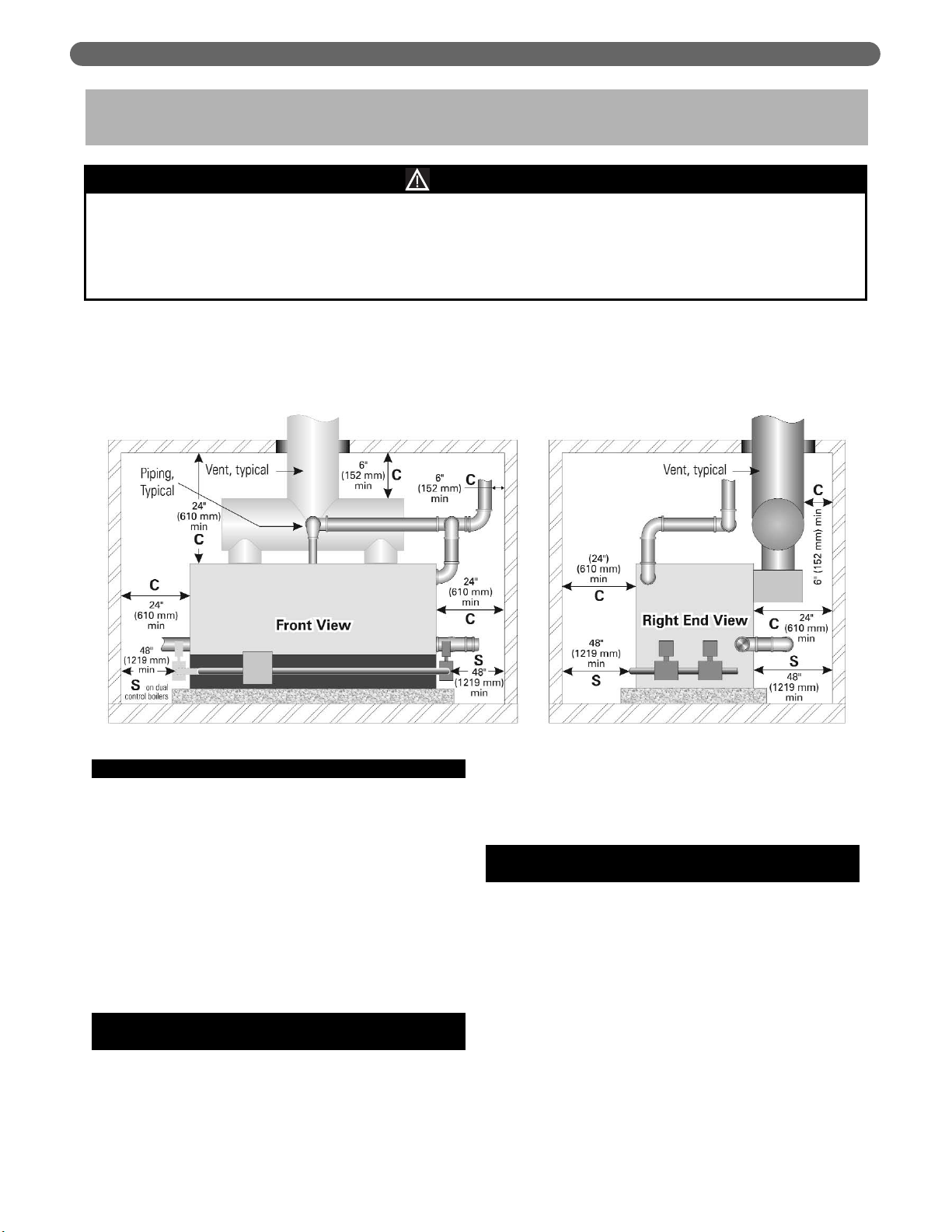
1. The following recommendations allow for reasonable
access to the boiler. Local codes or special
conditions may require greater clearances.
a. For servicing the boiler: provide 48" (1219 mm)
between the control manifold and adjacent wall
or other appliance.
b. For access to draft hood or passage to access the
boiler control manifold(s): provide 48" (1219 mm)
between the side of the boiler and adjacent wall or
other appliance.
c. See Figure 1.1. Clearances with an “S” are
minimum clearances for service accessibility.
B. COMBUSTIBLE CONSTRUCTION
CLEARANCES
1. This boiler is design certified for the following
clearances to combustible construction.
• 24" (610 mm) between the front, top, sides and
rear of the jacket
• 6" (152 mm) from steam and hot water pipes
• 6" (152 mm) from vent connector
• See Figure 1.1. Clearances with a “C” indicate
minimum clearances from combustible
construction.
C. AIR FOR COMBUSTION AND
VENTILATION
1. Adequate combustion air and ventilation air must be
provided for this appliance in accordance with the
section of the National Fuel Gas Code entitled, “Air
for Combustion and Ventilation” or applicable
provisions of the local building code. Subsections 2
through 8 as follows are based on the National Fuel
Gas Code requirements.
1. PREINSTALLATION
The equipment shall be installed with those installation requirements of the authority having jurisdiction or, in the
absence of such requirements, to the current edition of the
National Fuel Gas Code
, ANSI Z223.1/NFPA 54 and/or
CAN/CGA B149 Installation Codes.
Where required by the authority having jurisdiction, the installation must conform to
American Society of
Mechanical Engineers Safety Code for Controls and Safety Devices for Automatically Fired Boilers,
ASME CSD-1.
NOTICE
Read these instructions carefully before beginning the installation.
Study the control folder and consult drawings.
A shipping list is enclosed with each boiler, listing the items packed at the factory. Check the list as you unpack parts. If any parts
are missing or damaged, report the problem to the delivering carrier immediately.
Figure 1.1: Clearance Requirements
Page 5
3
PREINSTALLATION
2. Required Combustion Air Volume: The total required
volume of indoor air is to be the sum of the required
volumes for all appliances located within the space.
Rooms communicating directly with the space in
which the appliances are installed and through
combustion air openings sized as indicated in
Subsection 3 are considered part of the required
volume. The required volume of indoor air is to be
determined by one of two methods.
a. Standard Method: The minimum required
volume of indoor air (room volume) shall be 50
cubic feet per 1000 BTU/Hr (4.8 m
3
/kW). This
method is to be used if the air infiltration rate is
unknown or if the rate of air infiltration is known
to be greater than 0.6 air changes per hour. As
an option, this method may be used if the air
infiltration rate is known to be between 0.6 and
0.4 air changes per hour. If the air infiltration rate
is known to be below 0.4 then the Known Air
Infiltration Rate Method must be used. If the
building in which this appliance is to be installed
is unusually tight, PB Heat recommends that the
air infiltration rate be determined.
b. Known Air Infiltration Rate Method:
Where the air infiltration rate of a structure is
known, the minimum required volume of indoor
air for appliances other than fan assisted and
for the Series 211A Boiler shall be determined
as follows:
where:
I
other
= Input of appliances other than fan
assisted in Btu/hr
ACH = air change per hour (percent of the
volume of the space exchanged per
hour, expressed as a decimal)
For fan assisted appliances, calculate the required
volume of air using the following equation:
I
fan
= Input of the fan assisted appliances in
Btu/hr
Note: These calculations are not to be used for
infiltration rates greater than 0.60 ACH.
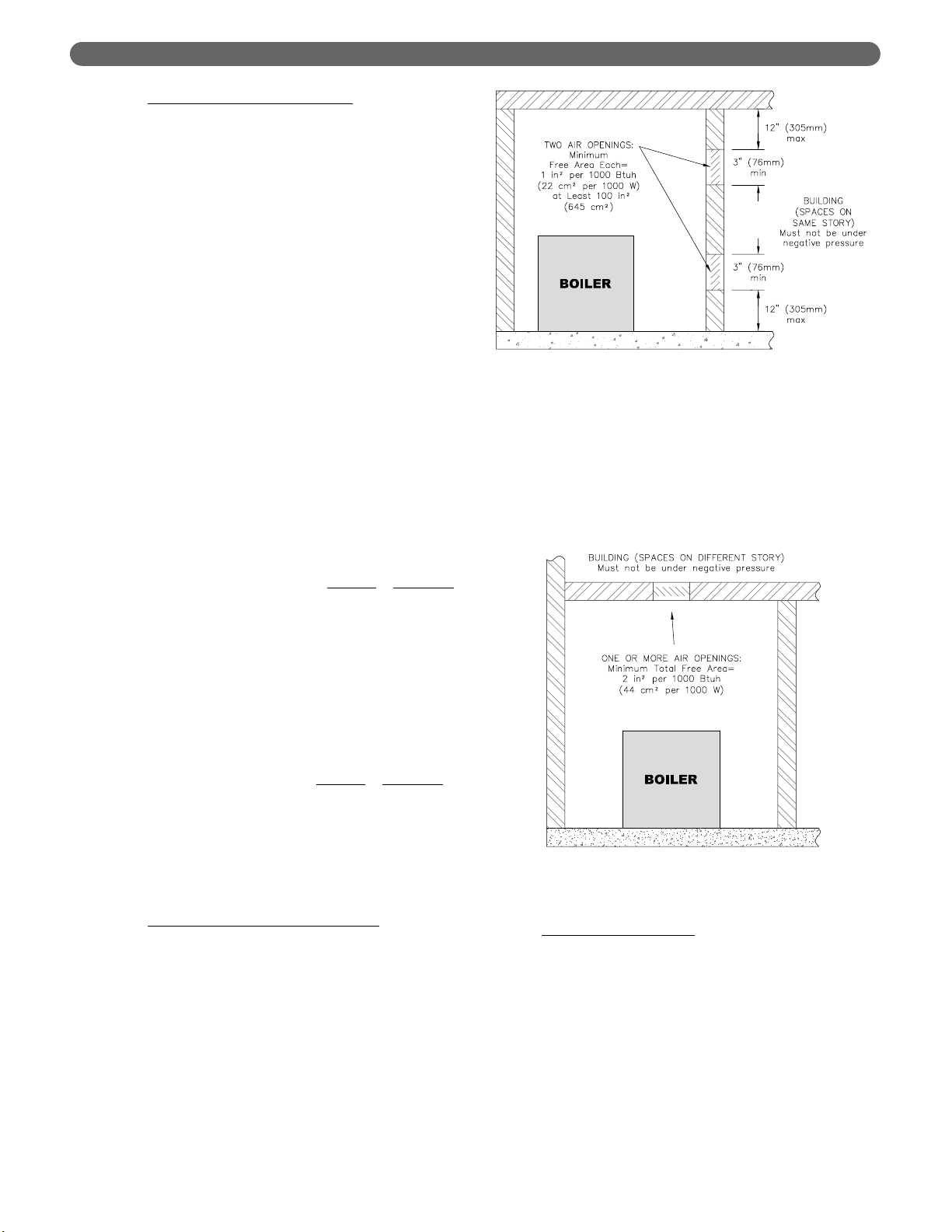
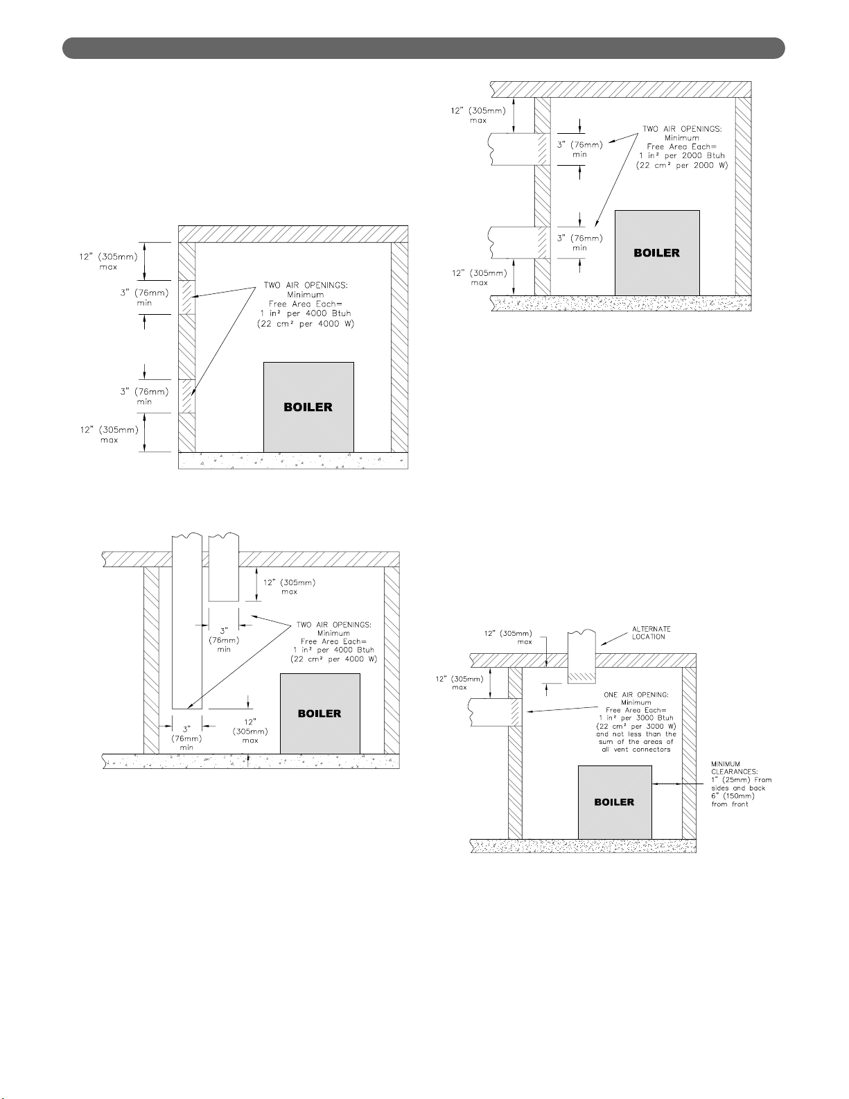
3. Indoor Air Opening Size and Location:
Openings
connecting indoor spaces shall be sized and located
as follows:
a. Combining spaces on the same floor:
Provide two permanent openings communicating
with additional spaces that have a minimum free
area of 1 in
2
per 1000 Btu/hr (22 cm2per 1000 W)
of the total input rating of all gas fired equipment
but not less than 100 in
2
(645 cm2). One
opening is to begin within 12 inches (305 mm)
from the top of the space and the other is to
begin within 12 inches (305 mm) from the floor.
The minimum dimension of either of these
openings shall be 3 inches (76 mm). See Figure
1.2 for an illustration of this arrangement.
b. Combining spaces on different floors:
Provide one or more permanent openings
communicating with additional spaces that have
a total minimum free area of 2 in
2
per 1000
Btu/hr (44 cm
2
per 1000 W) of total input rating
of all equipment. See Figure 1.3 for an
illustration of this arrangement.
4. Outdoor Combustion Air:
Outdoor combustion air is
to be provided through one or two permanent
openings. The minimum dimension of these air
openings is 3 inches (76 mm).
a. Two Permanent Opening Method: Provide
two permanent openings. One opening is to
begin within 12 inches (305 mm) of the top of
the space and the other is to begin within 12
inches (305 mm) of the floor. The openings are
to communicate directly or by ducts with the
outdoors or with spaces that freely communicate
with the outdoors. The size of the openings shall
be determined as follows:
21 ft
3
I
other
ACH 1000
Btu
/
hr
Required Volume
other
=
⎛
⎜
⎝
⎛
⎜
⎝
15 ft
3
I
fan
ACH 1000
Btu
/
hr
Required Volume
fan
=
⎛
⎜
⎝
⎛
⎜
⎝
Figure 1.2: Air Openings – All Air from Indoors
on the Same Floor
Figure 1.3: Air Openings – All Air from Indoors
on Different Floors
Page 6
4
i. Where communicating directly or through
vertical ducts with the outdoors each opening
shall have a minimum free area of 1 in
2
per
4000 Btu/hr (22 cm
2
per 4000 W) of total
input rating for all equipment in the space.
See Figure 1.4 for openings directly
communicating with the outdoors or Figure
1.5 for openings connected by ducts to the
outdoors.
ii. Where communicating with the outdoors
through horizontal ducts, each opening shall
have a minimum free area of 1 in
2
per 2000
Btu/hr (22 cm
2
per 2000 W) of total rated
input for all appliances in the space. See
Figure 1.6.
b. One Permanent Opening Method: Provide
one permanent opening beginning within 12
inches (305 mm) of the top of the space. The
opening shall communicate directly with the
outdoors, communicate through a vertical or
horizontal duct, or communicate with a space
that freely communicates with the outdoors.
The opening shall have a minimum free area of
1 in
2
per 3000 Btu/hr of total rated input for all
appliances in the space and not less than the
sum of the cross-sectional areas of all vent
connectors in the space. The gas-fired equipment
shall have clearances of at least 1 inch (25 mm)
from the sides and back and 6 inches (150 mm)
from the front of the appliance. See Figure 1.7
for this arrangement.
Figure 1.4: Air Openings – All Air Directly from
Outdoors
Figure 1.5: Air Openings – All Air from Outdoors
through Vertical Ducts
Figure 1.6: Air Openings – All Air from Outdoors
through Horizontal Ducts
Figure 1.7: Air Openings – All Air from Outdoors
through One Opening
PREINSTALLATION
Page 7

5
5. Combination Indoor and Outdoor Combustion Air: If
the required volume of indoor air exceeds the
available indoor air volume, outdoor air openings or
ducts may be used to supplement the available
indoor air provided:
a. The size and location of the indoor openings
comply with Subsection 3.
b. The outdoor openings are to be located in
accordance with Subsection 4.
c. The size of the outdoor openings are to be sized
as follows:
where:
A
req
= minimum area of outdoor openings.
A
full
= full size of outdoor openings calculated
in accordance with Subsection 4.
V
avail
= available indoor air volume
V
req
= required indoor air volume
6. Engineer
ed Installations: Engineered combustion air
installations shall provide an adequate supply of
combustion, ventilation, and dilution air and shall be
approved by the authority having jurisdiction.
7. Mechanical Combustion Air Supply
:
a. In installations where all combustion air is
provided by a mechanical air supply system, the
combustion air shall be supplied from the
outdoors at the minimum rate of 0.35 ft
3
/min per
1000 Btu/hr (0.034 m
3
/min per 1000 W) of the
total rated input of all appliances in the space.
b. In installations where exhaust fans are installed,
additional air shall be provided to replace the
exhaust air.
c. Each of the appliances served shall be
interlocked to the mechanical air supply to
prevent main burner operation when the
mechanical air supply system is not in operation.
d. In buildings where the combustion air is provided
by the mechanical ventilation system, the system
shall provide the specified combustion air rate in
addition to the required ventilation air.
8. Louvers & Grills:
a. The required size of openings for combustion,
ventilation, and dilution air shall be based on the
net free area of each opening.
i. Where the free area through a louver or grille
is known, it shall be used in calculating the
opening size required to provide the free area
specified.
ii. Where the free area through a louver or grille
is not known, it shall be assumed that wooden
louvers will have 25% free area and metal
louvers and grilles will have 75% free area.
iii. Nonmotorized dampers shall be fixed in the
open position.
b. Motorized dampers shall be interlocked with the
equipment so that they are proven in the full
open position prior to ignition and during
operation of the main burner.
i. The interlock shall prevent the main burner
from igniting if the damper fails to open
during burner startup.
ii. The interlock shall shut down the burner if
the damper closes during burner operation.
9. Combustion Air Ducts
a. Ducts shall be constructed of galvanized steel or
an equivalent corrosion- resistant material.
b. Ducts shall terminate in an unobstructed space,
allowing free movement of combustion air to the
appliances.
c. Ducts shall serve a single space.
d. Ducts shall not serve both upper and lower
combustion air openings where both such
openings are used. The separation between ducts
serving upper and lower combustion air
openings shall be maintained to the source of
combustion air.
e. Ducts shall not be screened where terminating in
an attic space.
f. Horizontal upper combustion air ducts shall not
slope downward toward the source of the
combustion air.
g. The remaining space surrounding a chimney
liner, gas vent, special gas vent, or plastic piping
installed within a masonry, metal, or factory built
chimney shall not be used to supply combustion
air.
h. Combustion air intake openings located on the
exterior of buildings shall have the lowest side of
the combustion air intake opening at least 12
inches (305 mm) above grade.
D. CHIMNEY OR VENT
1. Inspect the existing chimney or vent system. Make
sure it is in good condition. Inspect chimney liner
and repair or replace if necessary.
2. The vent system and installation must be in
accordance with the current edition of the National
Fuel Gas Code, ANSI Z223.1/NFPA 54, under
“Venting of Equipment”, or CAN/CGA B149,
Installation codes, under “Venting Systems and Air
Supply for Appliances”, or applicable provisions of
the local building codes.
PREINSTALLATION
V
avail
1 –
V
req
A
req
= A
full
⎛
⎜
⎝
⎛
⎜
⎝
Page 8
6
PREINSTALLATION
3. Chimney/Vent Operation: The vent system must be
sized and installed to provide the draft needed to
remove all combustion products. If the vent system
does not provide enough draft, combustion products
will spill into the building from the draft hood relief
opening. If spillage of combustion products occurs,
check the vent system, the combustion and
ventilation openings and make sure the boiler room
is never under negative pressure.
4. Exterior Vents
a. If the vent is outside, make sure it is insulated
sufficiently to ensure adequate draft.
5. Vent Sizing:
a. Individual vents: Use vent piping the same
diameter as the boiler vent connection. The
minimum height is 10 feet (305 cm) above the
bottom of the draft hood (relief opening). The
vent must also extend above the roof or any
obstructions as outlined in the current edition of
the National Fuel Gas Code, ANSI Z223.1/NFPA
54 and/or CAN/CGA B149, Installation Codes or
as required by local codes.
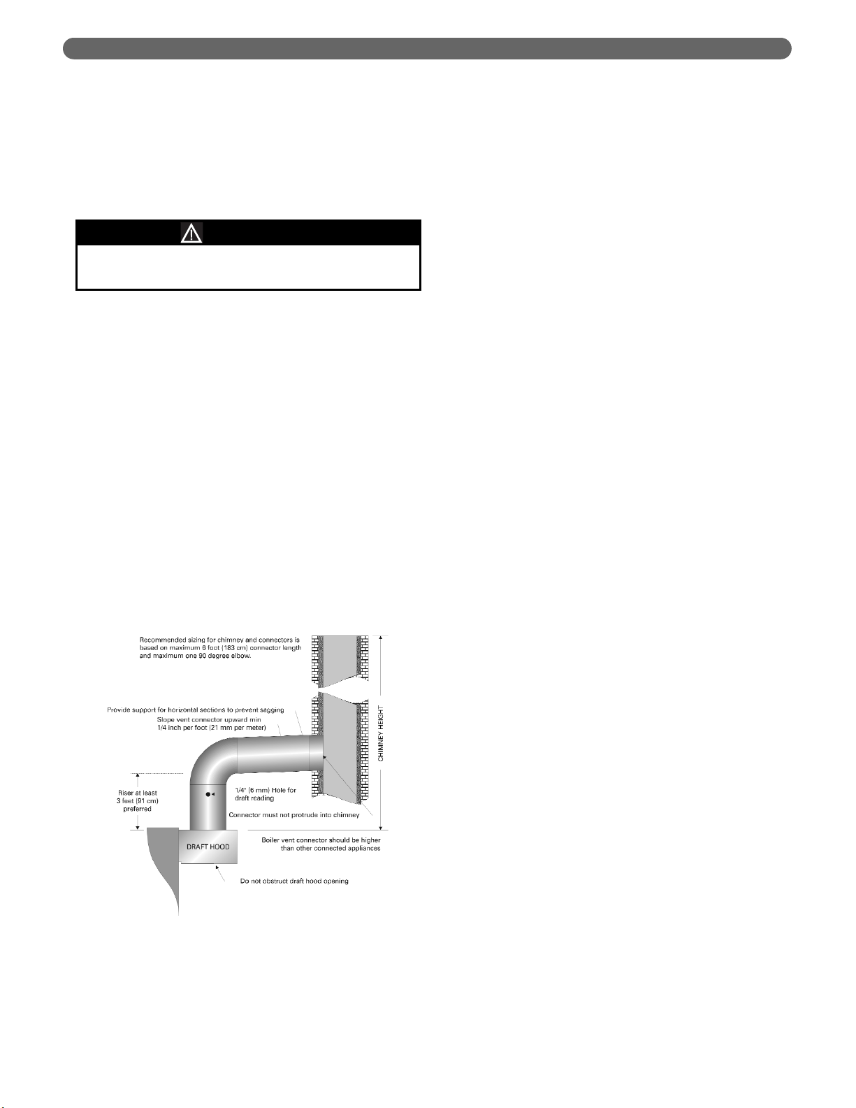
b. Combined vent breeching:
• The recommended sizing in Section 14, Boiler
Ratings & Dimensions, in this Manual is based
on a minimum chimney or vent height of 20
feet (610 cm) and a maximum horizontal run
of 6 feet (183 cm) to the chimney with no
more than one 90-degree standard elbow.
• The minimum area of the chimney serving
two or more appliances must be at least the
area of the largest chimney connector plus
50% of the total area of all other appliance
connectors.
• The vent connector must be single wall steel
or Type B double wall vent pipe. The vent
connector must be Type B double wall if it is
located in or passes through cold areas. The
vent connector must extend into, but not
beyond, the inside wall of the chimney.
6. Vent Connection to Boiler (Figure 1.8):
a. Provide at least a 3 foot (91 cm) rise in the vent
connection on the boiler.
b. The vent system should provide a draft of at least
0.02" w.c. (5 Pa) measured at the vent
connections.
c. Support the weight of the vent system
independently of the boiler draft hood. The draft
hood is not designed to carry structural loading.
d. Provide support of the vent connector
(breeching) at maximum 12 foot (366 cm)
intervals to prevent sagging and to provide a
minimum upward slope of 1/4" per foot (21 mm
per meter).
e. Do not connect the vent for this boiler into any
vent system which operates with positive
pressure.
f. Use Type B double-wall pipe for vents which run
through unheated spaces.
7. Removing an existing boiler from a common vent: At
the time for removal of an existing boiler, the
following steps shall be followed with each appliance
connected to the common venting system placed in
operation, while the other appliances remaining
connected to the common venting system are not in
operation.
a) Seal any unused openings in the common
venting system.
b. Visually inspect the venting system for proper size
and horizontal pitch and determine there is no
blockage or restriction, leakage, corrosion and
other deficiencies which could cause an unsafe
condition.
c. Insofar as is practical, close all building doors
and windows and all doors between the space in
which the appliances remaining connected to the
common venting system are located and other
spaces of the building. Turn on clothes dryers
and any appliance not connected to the common
venting system. Turn on any exhaust fans, such
as range hoods and bathroom exhausts, so they
will operate at maximum speed. Do not operate
a summer exhaust fan. Close fireplace dampers.
d. Place in operation the appliance being inspected.
Follow the lighting instructions. Adjust the
thermostat so appliance will operate continuously.
e. Test for spillage at the draft hood relief opening
after 5 minutes of main burner operation. Use
the flame of a match or candle, or smoke from a
cigarette, cigar or pipe.
Failure to provide adequate venting can result in
severe property damage, personal injury or death.
WARNING
Figure 1.8: Vent Connection
Page 9
7
PREINSTALLATION
f. After it has been determined that each appliance
remaining connected to the common venting
system properly vents when tested as outlined
above, return doors, windows, exhaust fans,
fireplace dampers and any other gas-burning
appliance to their previous condition of use.
g. Any improper operation of the common venting
system should be corrected so the installation
conforms with the current edition of the National
Fuel Gas Code, ANSI Z223.1/NFPA 54 and/or
CAN/CGA B149, the common venting system
should be resized to approach the minimum size
as determined using the appropriate tables
located in the chapter Sizing of Category I
Venting Systems in the current edition of the
National Fuel Gas Code, ANSI Z223.1/NFPA 54
and/or CAN/CGA B149, Installation Codes.
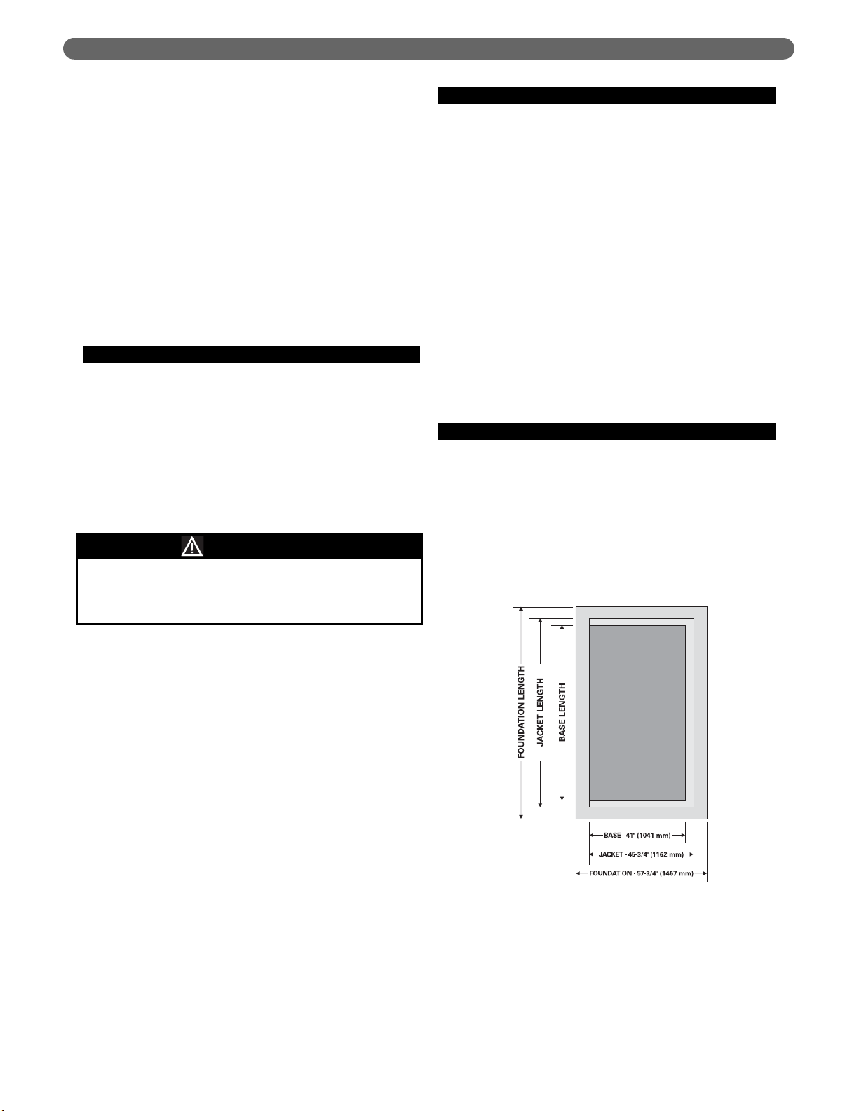
E. BOILER SETTING
1. Provide a good, level foundation for the boiler with
the minimum dimensions given in Table 1.1. The
flooring and structural support system must be
suitable for the operating weight of the boiler and
any connected piping.
2. Do not operate the boiler until the foundation, if new
concrete, has thoroughly cured. The high
temperature under the burners could cause major
damage to the concrete if it still contains moisture.
3. If the boiler is installed in a penthouse or if wiring of
any sort is run underneath the boiler foundation,
construct the foundation with provision for air flow
underneath between the main floor and the top of
the boiler foundation.
a. Concrete block aligned with the openings
connected continuously would serve this
purpose, for example.
b. If the foundation must be a concrete slab, use an
air cell high temperature insulating board, at least
1/2 inch (13 mm) thick, with aluminum backing,
aluminum side up. 1/2 inch (13 mm) Hi Temp
millboard with aluminum backing would be
acceptable as well. Place the insulating board on
the slab inside the base.
F. WATER QUALITY AND MAKE-UP
1. Check the system to make sure there are no leaks or
overfilling problems which might cause excessive
make-up water to be added. Make-up water causes
liming in the boiler and brings in oxygen. Oxygen
can cause severe damage to the boiler through
oxygen corrosion pitting.
2. Make sure the expansion tank and automatic fill
valve (if used) are operating correctly. If either of
these causes high pressure in the system, the boiler
relief valve will weep or open, allowing fresh water to
enter the system.
3. Make sure the system controls don’t subject the
boiler to excessively low water temperatures, which
would cause condensation of flue gases and
corrosion of the boiler.
4. Do not use chemicals or substances in the
boiler or system which contain petroleum or its
derivatives. This will damage the boiler seals.
G. INSTALLATION SURVEY
For new and existing installations, a Water Installation
Survey is available from PB Heat, LLC. The survey will
provide information on how a water boiler works with
your specific system and will provide an overview of
water system operation in general.
You can also use this survey to locate system problems
which will have to be corrected. To obtain copies of the
Water Installation Survey, contact your PB Heat
representative or download it from PeerlessBoilers.com.
Do not install this boiler on carpeting or any
combustible flooring. A significant fire hazard could
result, with potential for property damage, personal
injury or death.
WARNING
Figure 1.9: Foundation Layout
Page 10

8
PREINSTALLATION
Boiler
Boiler Base Length Jacket Length Foundation Length
Model inches
mm inches mm inches mm
211A-04 22-1/2 572 28-1/8 714 40-1/8 1019
211A-05 28-1/8 714 33-3/4 857 45-3/4 1162
211A-06 33-3/4 857 39-3/8 1000 51-3/8 1305
211A-07 39-3/8 1000 45 1143 57 1448
211A-08 45 1143 50-5/8 1286 62-5/8 1591
211A-09 50-5/8 1286 56-1/4 1429 68-1/4 1734
211A-10 56-1/4 1429 61-7/8 1572 73-7/8 1876
211A-11 61-7/8 1572 67-1/2 1714 79-1/2 2019
211A-12 67-1/2 1714 73-1/8 1857 85-1/8 2162
211A-13 73-1/8 1857 78-3/4 2000 90-3/4 2305
211A-14 78-3/4 2000 84-3/8 2143 96-3/8 2448
211A-15 84-3/8 2143 90 2286 102 2591
211A-16 90 2286 95-5/8 2429 107-5/8 2734
211A-17 95-5/8 2429 101-1/4 2572 113-1/4 2877
211A-18 101-1/4 2572 106-7/8 2715 118-7/8 3019
211A-19 106-7/8 2715 112-1/2 2857 124-1/2 3162
211A-20 112-1/2 2857 118-1/8 3000 130-1/8 3305
211A-21 118-1/8 3000 123-3/4 3143 135-3/4 3448
211A-22 123-3/4 3143 129-3/8 3286 141-3/8 3591
211A-23 129-3/8 3286 135 3429 147 3734
211A-24 135 3429 140-5/8 3572 152-5/8 3877
211A-25 140-5/8 3572 146-1/4 3715 158-1/4 4020
211A-26 146-1/4 3715 151-7/8 3858 163-7/8 4162
211A-27 151-7/8 3858 157-1/2 4000 169-1/2 4305
211A-28 157-1/2 4000 163-1/8 4143 175-1/8 4448
211A-29 163-1/8 4143 168-3/4 4286 180-7/8 4594
211A-30 168-3/4 4286 174-3/8 4429 186-3/8 4734
211A-31 174-3/8 4429 180 4572 192 4877
211A-32 180 4572 185-5/8 4715 197-5/8 5020
211A-33 185-5/8 4715 191-1/4 4858 203-1/4 5163
211A-34 191-1/4 4858 196-7/8 5001 208-7/8 5305
211A-35 196-7/8 5001 202-1/2 5143 214-1/2 5448
211A-36 202-1/2 5143 208-1/8 5286 220-1/8 5591
211A-37 208-1/8 5286 213-3/4 5429 225-3/4 5734
211A-38 213-3/4 5429 219-3/8 5572 231-3/8 5877
211A-39 219-3/8 5572 225 5715 237 6020
211A-40 225 5715 230-5/8 5858 242-5/8 6163
211A-41 230-5/8 5858 236-1/4 6001 248-1/4 6306
211A-42 236-1/4 6001 241-7/8 6144 253-7/8 6448
211A-43 241-7/8 6144 247-1/2 6286 259-1/2 6591
211A-44 247-1/2 6286 253-1/8 6429 265-1/8 6734
211A-45 253-1/8 6429 258-3/4 6572 270-3/4 6877
211A-46 258-3/4 6572 264-3/8 6715 276-3/8 7020
Table 1.1: Boiler Foundation Layout
Page 11
9
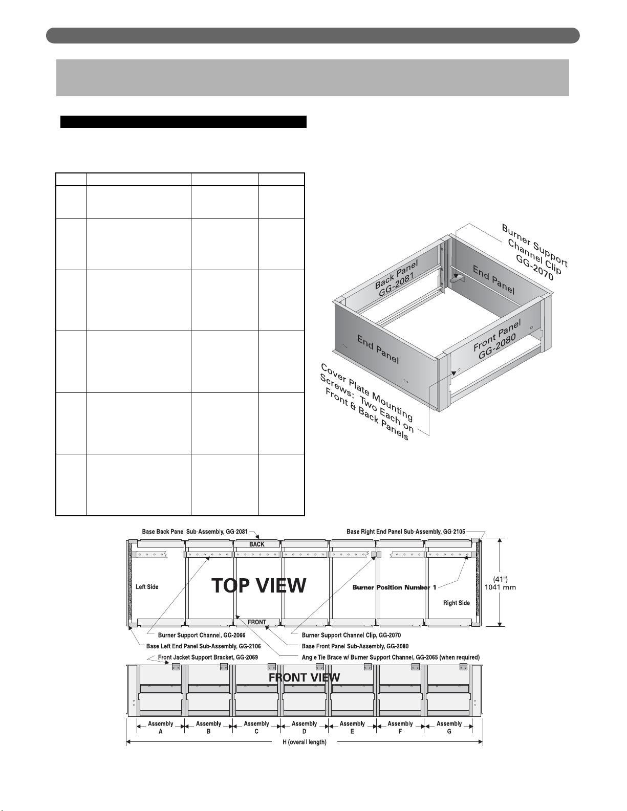
A. BASE ASSEMBLY
1. Collect the crates containing the Base Assembly
parts. Table 2.1 shows the quantity of each crate
required. The crates contain the following parts:
2. Open crate number 2. Remove the End Panels and
mount a Support Channel Clip toward the rear on
each panel as shown in Figure 2.2 using 1/4"-20 x
1/2" (13 mm) round head machine screws and 1/4"
lock washers provided.
ASSEMBLE THE BASE
2. ASSEMBLE THE BASE
2
2AA
2BB
2CC
2DD
2EE
Crate
Right End Panel Sub-Assembly
Left End Panel Sub-Assembly
Burner Support Channel Clips (2)
Front Panel Sub-Assembly
Back Panel Sub-Assembly
Burner Support Channel
Front Panel Support Bracket
Section Assembly Kit
Front Panel Sub-Assembly
Back Panel Sub-Assembly
Burner Support Channel
Angle Tie Brace
Front Panel Support Bracket
Section Assembly Kit
Front Panel Sub-Assembly
Back Panel Sub-Assembly
Burner Support Channel
Angle Tie Brace
Front Panel Support Bracket
Section Assembly Kit
Front Panel Sub-Assembly
Back Panel Sub-Assembly
Burner Support Channel
Angle Tie Brace
Front Panel Support Bracket
Section Assembly Kit
Front Panel Sub-Assembly
Back Panel Sub-Assembly
Burner Support Channel
Angle Tie Brace
Front Panel Support Bracket
Section Assembly Kit
Items
90338
90340
90341
90342
90343
90344
Sub-Assembly #
GG-2112
GG-2113
GG-2070
GG-2080
GG-2081
GG-2066
GG-2069
GG-1030
GG-2080-1
GG-2081-1
GG-2066-1
GG-2065
GG-2069
GG-1030
GG-2080-2
GG-2081-2
GG-2066-2
GG-2065
GG-2069
GG-1030-1
GG-2080-3
GG-2081-3
GG-2066-3
GG-2065
GG-2069
GG-1030-2
GG-2080-4
GG-2081-4
GG-2066-4
GG-2065
GG-2069
GG-1030-3
Par t #
Figure 2.2: Steel Base Assembly
Figure 2.1: Boiler Base Assembly
Page 12
10
3. Attach the Front Panel and Back Panel (Figure 2.2) to
the Left Hand End Panel using 5/16"-18 x 1" (25 mm)
long cap screws and hex head nuts provided.
4. For 211A-04 through 211A-08 Only:
a. Complete the base assembly by attaching the
Right End Panel and setting the Burner Support
Channel on the clips.
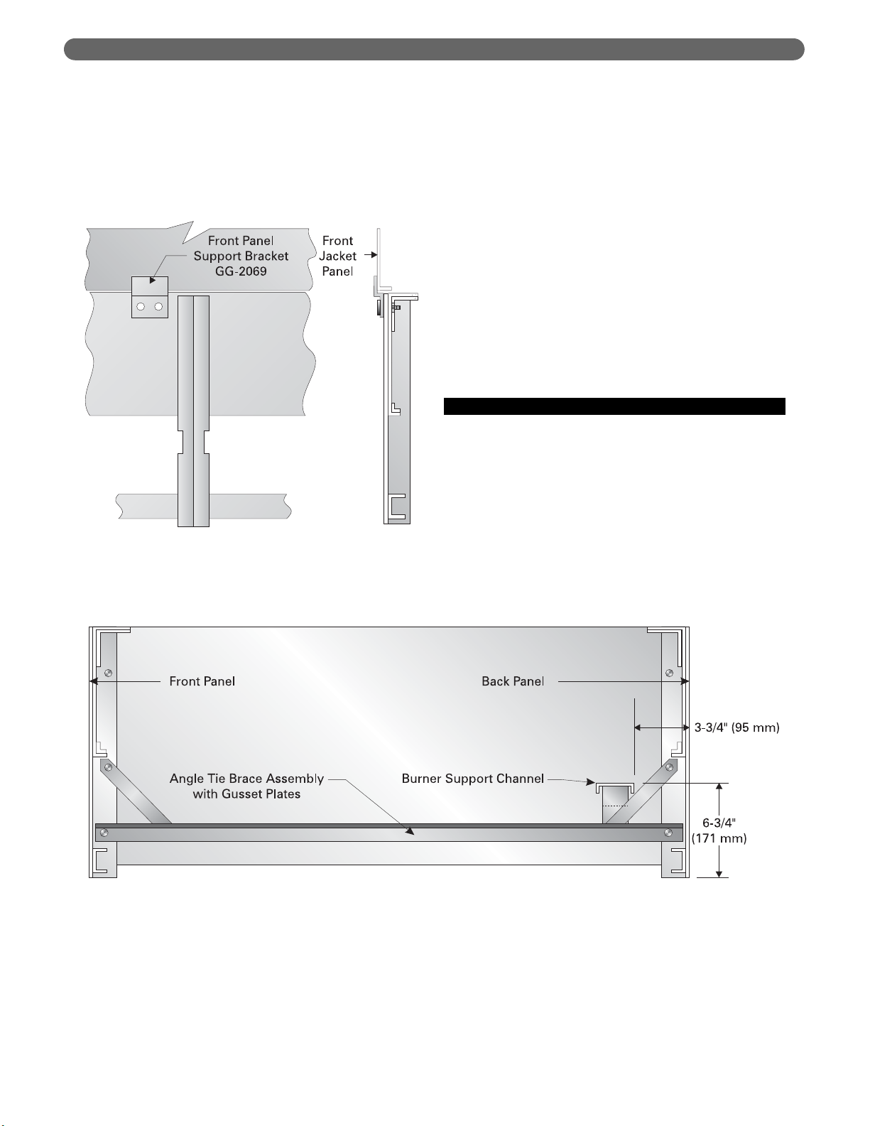
5. For 211A-09 through 211A-46 Only:
a. Attach a Front Panel Support Bracket to each
Front Panel as shown in Figure 2.4.
6. Bolt remaining Front and Back Panels together
using 5/16"-18 x 1" (25 mm) cap screws and hex
head nuts. See Table 2.1 for panels required. Place
the panels in the positions shown in the table and
Figure 2.1.
7. Attach an Angle Tie Brace at each panel joint to
secure the front and back panels as shown in Figure
2.3 using 5/16"-18 x 1" (25 mm) cap screws and hex
head nuts.
8. Complete the base assembly by attaching the Right
Hand End Panel using 5/16"-18 x 1" (25 mm) cap
screws and hex head nuts.
9. Set the Burner Support Channels in place as shown
in Figure 2.1.
B. INSTALL THE PILOT BURNERS
1. Check the location of the Burner Support Channels
in the Base Assembly. The dimensions should be:
a. Height above boiler foundation: 6-3/4" (171 mm)
b. Distance from back of Base: 3-3/4" (95 mm)
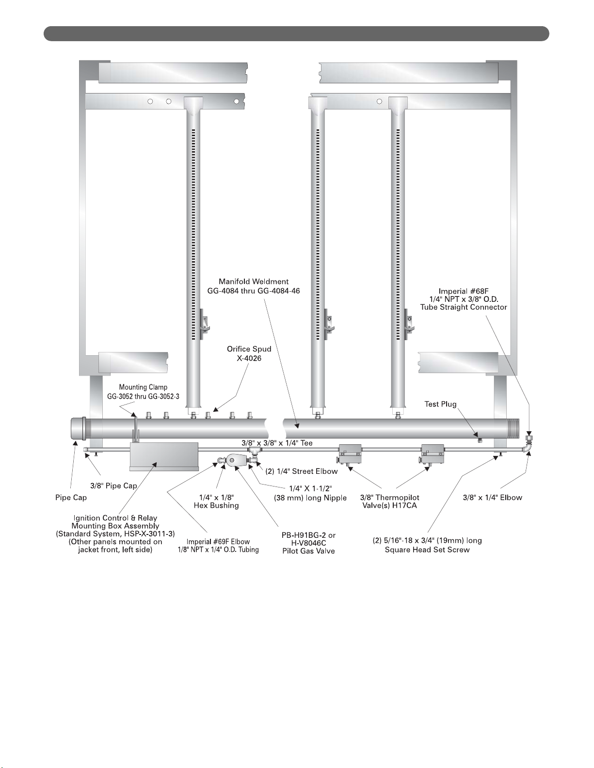
2. Remove the Gas Manifold and Pilot Line Assembly
from Box Number 7.
3. Place Manifold on front of Base. Bolt the hangers
using 5/16"-18 x 1" (25 mm) long cap screws with
5/16" flat washers. See Figure 2.5.
ASSEMBLE THE BASE
Figure 2.4: Support Bracket Installation
Figure 2.3: Angle Tie Brace Installation
Page 13
11
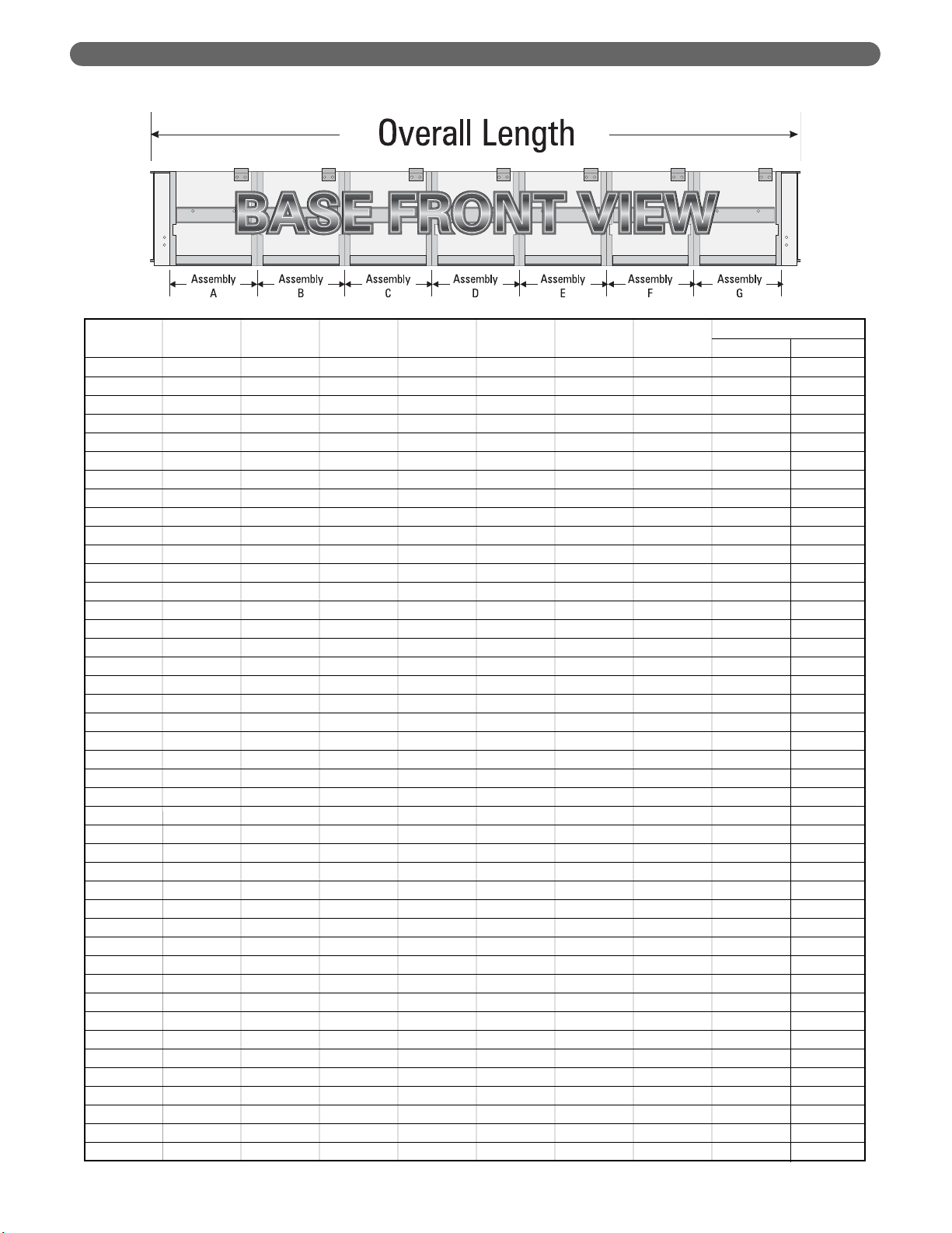
ASSEMBLE THE BASE
Model
ABCDEFG
Number
211A-04 2AA ——————24-3/4" 629
211A-05 2BB ——————30-3/8" 771
211A-06 2CC ——————36"914
211A-07 2DD ——————41-5/8" 1057
211A-08 2EE ——————47-1/4" 1200
211A-09 2BB 2BB —————52-7/8" 1343
211A-10 2CC 2BB —————58-1/2" 1486
211A-11 2CC 2CC —————64-1/8" 1629
211A-12 2DD 2CC —————69-3/4" 1772
211A-13 2DD 2DD —————75-3/8" 1915
211A-14 2EE 2DD —————81"2057
211A-15 2EE 14A —————86-5/8" 2200
211A-16 2CC 2CC 2CC ————92-1/4" 2343
211A-17 2DD 2CC 2CC ————97-7/8" 2486
211A-18 2EE 2CC 2CC ————8'-7-1/2" 2629
211A-19 2DD 2DD 2DD ————9'-1-1/8" 2772
211A-20 2EE 2EE 2CC ————9'-6-3/4" 2915
211A-21 2EE 2EE 2DD ————10'-0-3/8" 3058
211A-22 2EE 2EE 2EE ————10'-6" 3200
211A-23 2EE 2CC 2CC 2CC — — — 10'-11-5/8" 3343
211A-24 2DD 2DD 2DD 2CC — — — 11'-5-1/4" 3486
211A-25 2EE 2EE 2CC 2CC — — — 11'-10-7/8" 3629
211A-26 2EE 2EE 2EE 2BB — — — 12'-4-1/2" 3772
211A-27 2EE 2EE 2EE 2CC — — — 12'-10-1/8" 3915
211A-28 2EE 2EE 2EE 2DD — — — 13'-3-3/4" 4058
211A-29 2EE 2EE 2EE 2EE — — — 13'-9-3/8" 4201
211A-30 2DD 2DD 2DD 2DD 2CC — — 14'-3" 4343
211A-31 2DD 2DD 2DD 2DD 2DD — — 14'-8-5/8" 4486
211A-32 2EE 2DD 2DD 2DD 2DD — — 15'-2-1/4" 4629
211A-33 2EE 2EE 14B 2EE 2EE — — 15'-7-7/8" 4772
211A-34 2EE 2EE 2EE 2EE 2CC — — 16'-1-1/2" 4915
211A-35 2EE 2EE 2EE 2EE 2DD — — 16'-7-1/8" 5058
211A-36 2EE 2EE 2EE 2EE 2EE — — 17'-0-3/4" 5201
211A-37 2DD 2DD 2DD 2DD 2DD 2DD — 17'-6-3/8" 5344
211A-38 2EE 2DD 2DD 2DD 2DD 2DD — 18'-0" 5486
211A-39 2DD 2DD 2EE 2EE 2DD 2DD — 18'-5-5/8" 5629
211A-40 2BB 2EE 2EE 2EE 2EE 2EE — 18'-11-1/4" 5772
211A-41 2EE 2EE 2DD 2DD 2EE 2EE — 19'-4-7/8" 5915
211A-42 2DD 2EE 2EE 2EE 2EE 2EE — 19'-10-1/2" 6058
211A-43 2EE 2EE 2EE 2EE 2EE 2EE — 20'-4-1/8" 6201
211A-44 2EE 2BB 2EE 2EE 2EE 2BB 2EE 20'-9-3/4" 6344
211A-45 2CC 2BB 2EE 2EE 2EE 2EE 2EE 21'-3-3/8" 6487
211A-46 2CC 2CC 2EE 2EE 2EE 2EE 2EE 21'-9" 6629
mm
Table 2.1: Base Front and Back Panel Crates
feet/inches
Overall Length
Page 14
12
ASSEMBLE THE BASE
4. Place only the Burners with pilots mounted in the
locations given in Table 2.2. Install each Burner by
slipping the opening on the front of the burner over
the orifice adapter and slipping the pin on the end of
the burner into the hole in the Burner Support
Channel directly opposite the orifice.
5. Cut and fit the 1/4" aluminum tubing provided from
the pilot gas shut-off device(s) to the pilot burners.
6. Do not install the remaining burners until the Boiler
Sections are installed.
Figure 2.5: Typical Gas Manifold and Pilot Line Assembly
Page 15

13
ASSEMBLE THE BASE
Table 2.2: Pilot Burner Locations – Numbered Right to Left (See Figure 2.1)
Total
Natural Gas Only Propane Gas Only
Model Number of Number Pilot Burner Locations Pilot Burner Locations
Number Pilots of (Positions Numbered Right to Left) (Positions Numbered Right to Left)
Burners
211A-04 1 6 5 — 5 —
211A-05 1 8 5 — 5 —
211A-06 1 10 5 — 5 —
211A-07 1 12 5 — 5 —
211A-08 1 14 5 — 5 —
211A-09 1 16 5 — 5 —
211A-10 1 18 5 — 7 —
211A-11 2 20 15 5 13 5
211A-12 2 22 15 5 13 5
211A-13 2 24 17 5 13 5
211A-14 2 26 17 5 9, 19 —
211A-15 2 28 19 5 9, 21 —
211A-16 3 30 25 5, 15 5, 15, 23 —
211A-17 3 32 25 5, 15 5, 15, 25 —
211A-18 3 34 25 5, 15 9, 19, 27 —
211A-19 3 36 29 5, 17 9, 21, 29 —
211A-20 3 38 35 5, 21 9, 21, 31 —
211A-21 3 40 37 5, 23 9, 23, 33 —
211A-22 3 42 19 5, 39 9, 23, 35 —
211A-23 3 44 19 5, 41 9, 23, 37 —
211A-24 3 46 21 5, 39 9, 23, 39 —
211A-25 3 48 25 5, 45 9, 23, 41 —
211A-26 4 50 19 5, 33, 47 9, 23, 33, 45 —
211A-27 4 52 21 5, 35, 49 9, 23, 35, 45 —
211A-28 4 54 23 5, 37, 51 9, 23, 35, 47 —
211A-29 4 56 27 5, 39, 53 9, 23, 39, 49 —
211A-30 4 58 29 5, 39, 51 9, 23, 39, 51 —
211A-31 4 60 31 5, 41, 53 9, 23, 39, 53 —
211A-32 4 62 33 5, 41, 59 9, 25, 41, 55 —
211A-33 4 64 35 5, 41, 61 9, 25, 41, 57 —
211A-34 5 66 35 5, 21, 49, 63 9, 23, 39, 51, 59 —
211A-35 5 68 37 5, 17, 51, 65 9, 23, 39, 51, 61 —
211A-36 5 70 37 5, 19, 53, 67 9, 23, 39, 51, 63 —
211A-37 5 72 37 5, 23, 47, 65 9, 23, 39, 51, 65 —
211A-38 5 74 25, 55 5, 43, 67
211A-39 5 76 23, 49 5, 35, 69
211A-40 5 78 25, 55 5, 33, 75
211A-41 6 80 19, 45 5, 33, 57, 77
211A-42 6 82 23, 51 5, 31, 65, 79
211A-43 6 84 23, 53 5, 33, 67, 81
211A-44 6 86 21, 55 5, 33, 67, 83
211A-45 6 88 23, 57 5, 37, 65, 85
211A-46 6 90 25, 59 5, 39, 67, 87
Electronic Pilots Standing Pilots Electronic Pilots Standing Pilots
(Spark Ignited) (Thermocouple) (Manually Lighted) (Thermocouple)
Models 211A-38 through 211A-46
Are Certified for Natural Gas Only
Page 16
14
PLACE THE BOILER SECTIONS
A. PREPARATION
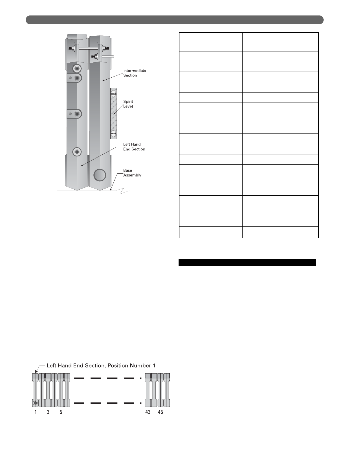
1. Check the level of the Boiler Base using a spirit level.
Make sure the base is level and that the base panels
are aligned within plus or minus 1/16" (2 mm).
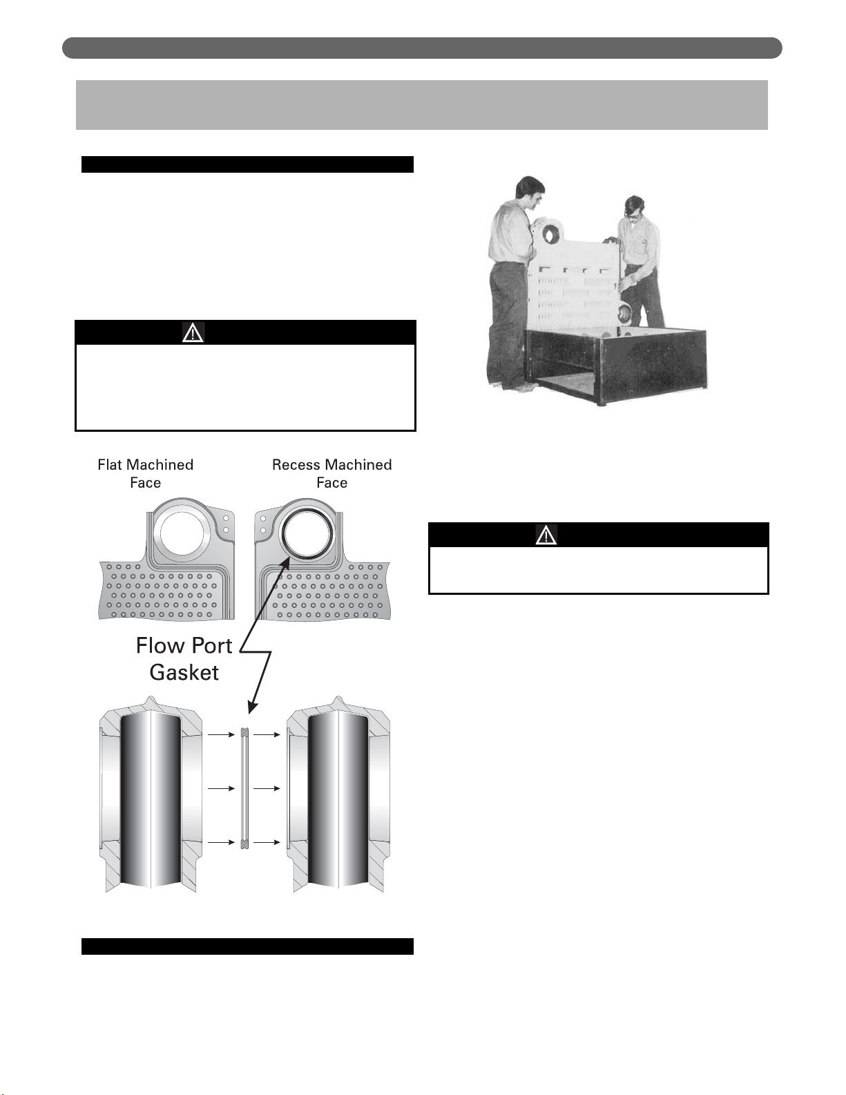
2. Check the area around the Flow Ports (Figure 3.1).
Use solvent and a clean cloth to thoroughly clean the
flat surfaces and recesses. All foreign matter must be
removed to assure a proper seal when the sections
are drawn together.
B. PLACING THE SECTIONS
1. Begin by placing the Left Hand End Section on the
left end of the base. The upper flow port goes
toward the front of the boiler as shown is Figure 3.2.
2. Slide the section to the back of the base until the cast
lug on the bottom of the section under the lower
flow port is against the base back panel. Keep the
section upright by a supporting prop or other means.
3. Align the parting line of the section with the seam
between the Base End panel and the Base Front
Panel as shown in Figure 3.3.
4. Apply Hi-Temp rope seal by spreading a thin coat of
Rope Adhesive or Spray Adhesive in the grooves on
each end of the section. Place the rope in the grooves.
Do not stretch the rope. The longer rope goes in the
front groove. NOTE: The ends of each rope must
extend 1/2" (13 mm) beyond the top and bottom.
5. Place the Flow Port Gaskets in the recesses provided
(see Figure 3.1). Do not use adhesive.
6. The following steps must be followed to insure that
no damage is done to the tie rod lugs. A 0-100 ft.-lbs.
(0-136 N
·
m) torque wrench is required.
a. Place an Intermediate Section on the base and
slide it carefully against the Left Hand End
Section.
b. Align the flow ports from front to back, as close
as possible.
c. Insert a tie rod into each of the lugs on each
section and apply a nut and washer to each end
of the tie rod.
d. Before tightening, check the vertical alignment of
the sections using a spirit level. See Figure 3.4.
Make sure they are square with the Base.
3. PLACE THE BOILER SECTIONS
Gaskets will be damaged by petroleum or its
derivatives. Completely remove all solvent residue
before placing gaskets.
Do not use petroleum based compounds in the boiler.
CAUTION
The sections are heavy and must be supported
securely.
WARNING
Figure 3.1: Flow Port Machining & Gasket
Figure 3.2: Placing the First Section on Base
Page 17
15
PLACE THE BOILER SECTIONS
Figure 3.3: Assembling Sections on Base
Page 18
16
PLACE THE BOILER SECTIONS
e. Draw sections together evenly, alternating
between top lug and bottom lug in increments of
20 ft.-lbs. (27 N
·
m). Continue until both top and
bottom lugs are tightened to 60 ft.-lbs. (81 N
·
m).
DO NOT EXCEED 60 FT.-LBS (81 N
·
m).
f. Check the level while tightening to make sure
alignment stays true. Also make sure sections
remain square with the Base from front to back
as the tie rods are tightened and as additional
sections are installed.
g. If the sections tend to run out of plumb, this will
usually be at the bottom front. Loosen the upper
nuts slightly and tighten the lower ones to adjust.
7. Assemble the remaining sections in the same way for
a finished assembly as shown in Figure 3.3.
8. Some of the Intermediate Sections have tappings for
installing additional risers from the boiler. These
Tapped Intermediate Sections must be installed as
shown in Figure 3.5A. The placement order is left to
right (Figure 3.5).
9. After all sections are mounted, apply the furnace
cement provided between the Base and the bottoms
of the sections.
C. HYDROSTATIC TEST THE BOILER
1. The supply and return piping can be permanently
erected before applying the Boiler Jacket if the pipe
nipples applied to the boiler tappings are long
enough to clear the jacket.
2. Install a drain cock in one of the tappings provided
at the bottom rear of each end section.
3. Provide a water supply line to the boiler.
4. Plug all open tappings in the boiler.
5. Provide a means to vent air as the boiler fills.
6. Fill the boiler with water, venting air as water level
rises.
7. Pressurize boiler to:
• 75 psig (517 kPa) for 50 psig (345 kPa) sections.
Do not exceed this pressure.
• 120 psig (827 kPa) for 80 psig (552 kPa)
sections. Do not exceed this pressure.
a. Maintain pressure while checking all joints and
fittings for leaks.
b. After inspection is complete, drain the boiler and
remove plugs from tappings that are to be used.
211A-29
211A-30
211A-31
211A-32
211A-33
211A-34
211A-35
211A-36
211A-37
211A-38
211A-39
211A-40
211A-41
211A-42
211A-43
211A-44
211A-45
211A-46
Boiler Model Number
Place Tapped Intermediate
Sections at Positions
(Numbered Left to Right)
10, 20
11, 21
10, 22
11, 23
13, 25
9, 17, 26
9, 18, 27
13, 21, 29
13, 21, 29
12, 22, 31
12, 20, 28
8, 16, 25, 33
12, 19, 26, 34
12, 20, 27, 35
7, 14, 22, 30, 37
8, 16, 23, 29, 37
7, 14, 21, 32, 39
7, 14, 22, 29, 36, 43
Figure 3.5: Section Positioning Numbering
Figure 3.5A: Section Position Numbering
Figure 3.4: Align Sections Vertically
Page 19

17
INSTALL THE FLUE COLLECTOR
1. Collect the Flue Collector cartons. The Flue Collector
sections are labeled on the part and on the carton.
See Table 4.1 for the items needed.
2. Install Hi Temp Rope for each collector section as
shown in Figure 4.1. The rope provides the seal to
prevent flue gases from leaking from the collector.
Make certain that the rope is well under the bottom
edges of each flue collector section in order to obtain
a tight seal.
3. Place the Flue Collector sections in the positions given
in Table 4.1. These positions are numbered from
left to right when facing the front of the
boiler.
4. Fasten an angle bracket, part number GG-5005, to
the top of each Collector section with two #10 x 1/2"
(13 mm) long sheet metal screws. See Figure 4.2.
5. Insert a Long Hook Bolt, part number GG-5003,
through the angle bracket. Slip the hook end over
the tie rod. Apply a 1/4"-20 hex nut on the end of
the rod and snug against the bracket. See Figure 4.2.
Do not tighten yet.
6. Insert a Short Hook Bolt, part number GG-5004,
through the flange in the rear of the flue collector.
Catch the hook around the spacer pads at the top of
the boiler sections. Apply a 1/4"-20 hex nut on the
Bolt and snug against the flange. See Figure 4.2. Do
not tighten yet.
7. Draw the Flue Collector sections tight against the
sealing rope by tightening the nuts on the Hook
Bolts. Draw the nuts evenly, alternating tightening.
4. INSTALL THE FLUE COLLECTOR
Figure 4.2: Installing Flue Collector Sections
Figure 4.1: Applying Flue Collector Hi Temp Rope Gasket
Page 20

18
INSTALL THE FLUE COLLECTOR
Boiler
Position Position Position Position Position Position Position Position Position
Model
123456789
Number
211A-04 14 ————————
211A-05 14A ————————
211A-06 14B ————————
211A-07 14 14 ———————
211A-08 14A 14 ———————
211A-09 14A 14A ———————
211A-10 14B 14A ———————
211A-11 14B 14B ———————
211A-12 14A 14A 14 ——————
211A-13 14A 14A 14A ——————
211A-14 14B 14A 14A ——————
211A-15 14B 14A 14B ——————
211A-16 14B 14B 14B ——————
211A-17 14A 14A 14A 14A —————
211A-18 14B 14A 14A 14A —————
211A-19 14A 14B 14B 14A —————
211A-20 14B 14B 14B 14A —————
211A-21 14B 14B 14B 14B —————
211A-22 14B 14A 14A 14A 14A ————
211A-23 14B 14B 14A 14A 14A ————
211A-24 14B 14B 14B 14A 14A ————
211A-25 14B 14B 14B 14B 14A ————
211A-26 14B 14B 14B 14B 14B ————
211A-27 14B 14B 14A 14A 14A 14A — — —
211A-28 14B 14B 14B 14A 14A 14A — — —
211A-29 14B 14B 14B 14B 14A 14A — — —
211A-30 14B 14B 14B 14B 14B 14A — — —
211A-31 14B 14B 14B 14B 14B 14B — — —
211A-32 14B 14B 14B 14A 14A 14A 14A — —
211A-33 14B 14B 14B 14B 14A 14A 14A — —
211A-34 14B 14B 14B 14B 14B 14A 14A — —
211A-35 14B 14B 14B 14B 14B 14B 14A — —
211A-36 14B 14B 14B 14B 14B 14B 14B — —
211A-37 14B 14B 14B 14B 14A 14A 14A 14A —
211A-38 14A 14A 14A 14B 14B 14B 14B 14B —
211A-39 14A 14A 14B 14B 14B 14B 14B 14B —
211A-40 14A 14B 14B 14B 14B 14B 14B 14B —
211A-41 14B 14B 14B 14B 14B 14B 14B 14B —
211A-42 14A 14A 14A 14A 14B 14B 14B 14B 14B
211A-43 14A 14A 14A 14B 14B 14B 14B 14B 14B
211A-44 14A 14A 14B 14B 14B 14B 14B 14B 14B
211A-45 14A 14B 14B 14B 14B 14B 14B 14B 14B
211A-46 14B 14B 14B 14B 14B 14B 14B 14B 14B
Table 4.1: Flue Collector Section Location (From Left to Right Facing Front of Boiler) – Crates
Crates 14 = Part number GG-5000 Crate 14A = Part number GG-5000-1
Crate 14B = Part number GG-5000-2
Page 21

19
PIPE THE BOILER
A. PREPARATION
1. Make sure the boiler has been pressure tested as
outlined in Section 3, “Place the Boiler Sections” in
this manual.
2. The Supply and Return piping can be installed
before installing the jacket. Use nipples long enough
to extend through the jacket.
B. SUPPLY AND RETURN PIPING
1. Always locate the return connection on the end of
the boiler opposite the supply connection. Pipe the
supply on the right end as shown in Figure 5.1 or on
the left as shown in Figure 5.2.
2. The suggested supply and return sizing in Table 5.1
and Section 14, “Boiler Ratings & Dimensions” is
based on a flow rate through the boiler equivalent to
a 20°F temperature rise/1 gpm flow for each 10,000
Btu/Hr of boiler output (11°C temperature rise/1.29
liters/minute for each kW of boiler output). Using
higher flow rates could cause poor water flow
distribution in the boiler. Lower flow rates (higher
5. PIPE THE BOILER
Figure 5.2: Alternate Piping, Left End Supply
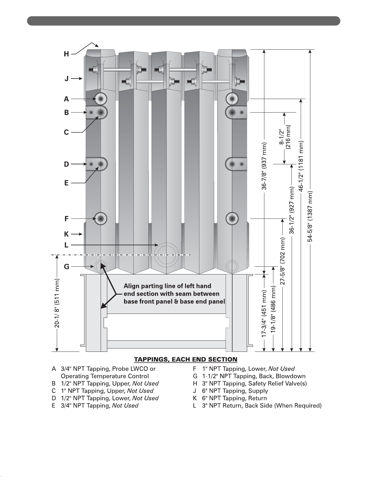
Figure 5.1: Piping Detail, Right End Supply (Tapped Intermediate Used on 211A-29 & Larger)
BOILER HEADER – Pipe
with offset to allow for header
expansion. Use Threaded
Fittings for Swing Joints.
3" NPT Tapping
Intermediate
Supply Connection
3/4" NPT Tapping for
Probe LWCO
Return
Threaded Fittings
6" NPT Tapping
End Section
Supply Connection
Supply
Install Reducing
Tee for Insertion
of High Limit Temp
Control Bulb Well
3/4" NPT Tapping
for Operating
Temp Control Bulb
Intermediate Section
Return Tapping, 3" NPT,
Tapped Intermediates Only
Base
Jacket
Page 22

20
PIPE THE BOILER
Table 5.1: Boiler Supply and Return Location & Sizing & Recommended Header Sizing
Flow Rate, End Intermediate
Boiler
20°F/11°C Supply Supply & Header
Model
Output Rise & Return Size,
Liter/ Return Size, inches
MBH kW GPM Min. Size, in. No. in.
211A-04 504 148 50 189 3 na na 3
211A-05 672 197 67 254 3 na na 3
211A-06 840 246 84 318 3 na na 3
211A-07 1,008 295 101 382 3 na na 3
211A-08 1,176 345 118 447 3 na na 3
211A-09 1,344 394 134 507 3 na na 3
211A-10 1,512 443 151 572 4 na na 4
211A-11 1,680 492 168 636 4 na na 4
211A-12 1,848 542 185 700 4 na na 4
211A-13 2,016 591 202 765 4 na na 4
211A-14 2,184 640 218 825 4 na na 4
211A-15 2,352 689 235 890 4 na na 4
211A-16 2,520 739 252 954 4 na na 4
211A-17 2,688 788 269 1,018 4 na na 4
211A-18 2,856 837 286 1,083 5 na na 5
211A-19 3,024 886 302 1,143 5 na na 5
211A-20 3,192 936 319 1,208 5 na na 5
211A-21 3,360 985 336 1,272 5 na na 5
211A-22 3,528 1,034 353 1,336 5 na na 5
211A-23 3,696 1,083 370 1,401 5 na na 5
211A-24 3,864 1,133 386 1,461 5 na na 5
211A-25 4,032 1,182 403 1,526 5 na na 5
Flow Rate, End Intermediate
Boiler
20°F/11°C Supply Supply & Header
Model
Output Rise & Return Size,
Liter/ Return Size, inches
MBH kW GPM Min. Size, in. No. in.
211A-26 4,200 1,231 420 1,590 5 na na 5
211A-27 4,368 1,280 437 1,654 5 na na 5
211A-28 4,536 1,330 454 1,719 5 na na 5
211A-29 4,704 1,379 470 1,779 4 2 3 5
211A-30 4,872 1,428 487 1,843 4 2 3 5
211A-31 5,040 1,477 504 1,908 4 2 3 5
211A-32 5,208 1,526 521 1,972 4 2 3 6
211A-33 5,376 1,576 538 2,037 4 3 3 6
211A-34 5,544 1,625 554 2,097 4 3 3 6
211A-35 5,712 1,674 571 2,161 4 3 3 6
211A-36 5,880 1,723 588 2,226 4 3 3 6
211A-37 6,048 1,773 605 2,290 4 3 3 6
211A-38 6,216 1,822 622 2,355 4 3 3 6
211A-39 6,384 1,871 638 2,415 4 3 3 6
211A-40 6,552 1,920 655 2,479 4 4 3 6
211A-41 6,720 1,970 672 2,544 4 4 3 6
211A-42 6,888 2,019 689 2,608 4 4 3 6
211A-43 7,056 2,068 706 2,672 4 5 3 6
211A-44 7,224 2,117 722 2,733 4 5 3 6
211A-45 7,392 2,167 739 2,797 4 5 3 6
211A-46 7,560 2,216 756 2,862 4 6 3 6
Page 23

21
PIPE THE BOILER
temperature rise) are acceptable provided the return
temperature to the boiler is at least 130°F (54°C) to
prevent condensation of flue gases.
3. Do not reduce the number or size of supply and
return connections given in Table 5.1. These are
required to control the flow velocities in the boiler
and maintain uniform distribution.
4. When the boiler is connected to heating coils located
in air handling units the boiler piping system must be
equipped with flow control valves or other automatic
devices to prevent gravity circulation of the boiler
water during the cooling cycle.
C. LOW SYSTEM TEMPERATURE
1. Low Return Temperature Piping, General
a. When the return temperature from the system
will be below 130°F (54°C) for extended periods
(heat pump systems, outdoor reset, snow melt,
etc.), provide piping and controls to protect the
boiler from condensation. Condensation will
damage the boiler and the burners and will lead
to shortened boiler life and maintenance
problems.
b. Temporary low temperature operation is
acceptable within limits. For occasional cold startups condensation will occur, but will have limited
effects. If the system is frequently allowed to cool
Figure 5.4: Fixed By-Pass Piping, Multiple Boilers
Figure 5.3: Fixed By-Pass Piping, Single Boiler
Page 24

22
PIPE THE BOILER
to room temperature, such as on night set-back
systems or energy management systems, cold
start-ups will occur often. These systems require
a Variable Low Temperature piping and control
arrangement, described below.
2. Constant Low Temperature
a. For systems with a relatively constant low
operating temperature (such as heat pump
systems), you can pipe a fixed flow by-pass
arrangement as shown in Figure 5.3. This piping
will not work for variable low temperature
systems such as outdoor reset systems or
primary/secondary systems with a large primary
circuit temperature drop. See Figure 5.4 for
multiple boilers.
3. Variable Low Temperature
a. When the return water temperature from the
system will vary (outdoor reset, snow melt, etc.) a
fixed bypass will not work. Fixed bypass piping
works by setting a high temperature rise through
the boiler. As the system return temperature rises
(during primary heating months, for example)
the boiler will cycle on the limit control
frequently, causing poor performance and
Figure 5.5: Piping for Variable Low Temperature, Single Boiler
Page 25

23
PIPE THE BOILER
excessive cycling. To protect the boiler and
provide proper operation, install a temperature
control valve and boiler circuit pump piped off of
the system as a secondary loop. See Figure 5.5
for single boilers and Figure 5.8 for multiple
boilers.
D. CHILLED WATER SYSTEMS
1. If the boiler will be used is conjunction with a
refrigeration system, the chilled medium must be
placed in parallel with the boiler and proper valves
applied to prevent the chilled medium from entering
the boiler. See Figure 5.6.
E. HIGH FLOW RATE PIPING
1. For flow rates higher than given in Table 5.1, provide
bypass piping around the boiler to limit the boiler
flow to that given in the table or pipe the boiler in a
secondary loop with its own pump as shown in
Figure 5.7.
F. MULTIPLE BOILER INSTALLATIONS
1. Multiple boilers should be piped in a secondary loop.
Each boiler should be provided with its own pump
and piped off of the secondary loop header. See
Figure 5.7 for systems with return temperature above
130°F (54°C). For low temperature systems, see
Figure 5.4 (constant low temperature systems) or
Figure 5.8 (variable low temperature systems).
2. You can use alternative piping if desired, such as
parallel piping or series piping in the primary system
loop. But these systems are less versatile.
a. With parallel piping, for instance, the system flow
conditions change if one or more of the boiler
shut-off valves are closed. It is difficult to pipe
parallel boilers to protect the boiler from low
return temperatures.
b. With series piping, temperature control to the
system is difficult because the temperature rise
equals the sum of the rises through each boiler.
Series piped boilers cannot be isolated for
servicing.
Page 26

24
PIPE THE BOILER
Figure 5.6: Piping to Isolate Boiler from Chilled Medium on Chiller Systems
Page 27

25
PIPE THE BOILER
Figure 5.7: Multiple Boiler Piping, System Return Temperature Above 54°C (130°F)
Page 28

26
PIPE THE BOILER
Figure 5.8: Piping for Variable Low Temperature Systems, Multiple Boilers
Page 29

INSTALL THE JACKET & DRAFT HOOD
A. PREPARE THE PARTS
1. Collect the Jacket cartons and Draft Hood cartons
(numbers 12 and 13).
2. See Figure 6.2 for the Jacket Assembly. Use these
drawings for part identification and location.
3. See Figure 6.3 for the quantity of each carton
required and placement of the jacket sections on
the boiler.
4. See Table 6.1 for the contents of each Jacket Carton
and Draft Hood carton.
5. See Table 6.2 for the Draft Hood cartons required.
B. APPLY CLEANOUT COVER PLATES
1. Remove Cleanout Cover Plates from Carton 12.
2. Install one cover plate on each End Section. Use four
5/16"-18 x 2" (51 mm) long studs, 5/16-18" hex nuts
and 5/16" flat washers.
3. Seal around the cleanout plates using the furnace
cement provided.
C. APPLY JACKET END ASSEMBLIES
1. Remove necessary knockouts from the Jacket End
Panel pieces in Carton 12.
2. Attach a Corner Panel Support Bracket (GG-6029)
to each Corner Panel using two #10 x 1/2" (13 mm)
long sheet metal screws.
3. Attach the four Corner Panels to the Base Ends using
1/4-20 x 1/2" (13 mm) long machine screws and flat
washers. The locations are:
• Right Front – GG-6015
• Left Front – GG-6016
• Right Rear – GG-6017
• Left Rear – GG-6018
4. Attach an End Panel Cover Plate (GG-6030) to the
opening on the Upper Left End Panel if the 6 inch
tapping on that end is not used.
5. Attach Upper Left End Panel (GG-6032) to the left
end corner panels with five #10 x 1/2" (13 mm) long
sheet metal screws
6. Place Top Left End Panel (GG-6020) over the
Corner Panels and Upper Panel with flange pointing
downward. Use four #10 x 1/2" (13 mm) long sheet
metal screws.
7. Repeat for the Right End.
D. 211A-04 THROUGH 211A-08 ONLY
1. Apply Front and Rear Panels as follows.
2. Open Jacket Intermediate Section carton, 12A, B, C,
D or E, per Table 6.1. Remove necessary knockouts
from panels.
3. Insert Front Panel (GG-6023) flange (on right side of
panel) under the edge of the Right Front Corner
Panel. Place the left edge of the Front Panel over the
offset flange of the Left Front Corner Panel. Line up
the screw holes and secure with ten #10 x 1/2"
(13 mm) long sheet metal screws.
4. Insert the offset flange of the Upper Rear Panel
under the edge of the Left Rear Corner Panel. Place
the left edge of the panel over the Right Rear Corner
Panel. Line up the holes and secure with ten #10 x
1/2" (13 mm) long sheet metal screws.
5. Apply the Lower Rear Panel using the same
procedure and secure with two #10 x 1/2" (13 mm)
long sheet metal screws.
6. Install Rear Panel Support Leg (GG-6028) inside the
Left Rear Corner Panel. The flanges extend toward
the boiler. Line up the holes and secure with three
#10 x 1/2" (13 mm) long sheet metal screws.
7. Attach the Lower Rear Panel Guide (GG-6031) to
the Rear Base Panel as shown in Figure 6.2.
8. Install the Draft Hood. Work from the left side (facing
the front) of the boiler to the right. Apply the Draft
Hood Sections in the sequence given in Table 6.2.
Attach the Hood sections to the Flue Collector with
two #10 x 1/2" (13 mm) long sheet metal screws per
collector section.
9. Insert the offset flange of the Jacket Top Panel under
the Top Left End Panel. Place the right flange on the
Top Right End Panel. The front edge flange goes over
the Jacket Front Panel. Line up the holes and secure
with #10 x 1/2" (13 mm) long sheet metal screws.
E. 211A-09 AND LARGER ONLY
1. The boilers have multiple intermediate jacket panels.
2. Collect the jacket cartons listed in Table 6.1. When
installing the jacket panels, place them on boiler in
the order shown in Figure 6.3.
3. Open the cartons in the order listed in Figure 6.3.
4. Install the Jacket Front Panels:
• Make sure to slip the Front Panels into the Front
Panel Support Brackets (mounted on the base).
See Figure 6.2.
• Install the first Front Panel with the left edge over
the Left Front Corner Panel. Line up the holes
and secure with #10 x 1/2" (13 mm) long sheet
metal screws.
• Continue applying Front Panels this way.
6. INSTALL THE JACKET & DRAFT HOOD
27
Page 30

28
INSTALL THE JACKET & DRAFT HOOD
• Slip the right edge of the last Front Panel under
the Right Front Corner Panel. Line up the holes
and secure with #10 x 1/2" (13 mm) long sheet
metal screws.
5. Install the Jacket Rear Panels:
• Slip the offset flange of the first Upper Rear Panel
under the edge of the Left Rear Corner Panel.
Secure with #10 x 1/2" (13 mm) long sheet
metal screws.
• Attach the first Lower Rear Panel in the same
way.
• Attach a Rear Panel Support Leg on the inside of
the Upper Rear Panel. The flanges point toward
the boiler. Attach with #10 x 1/2" (13 mm) long
sheet metal screws.
• Install a Panel Support Angle on the inside top
of the Upper Rear Panel (See Figure 6.2). Use
#10 x 1/2" (13 mm) long sheet metal screws.
• Install the remaining Upper Rear and Lower Rear
Panels in the same way.
• Place the edge of the last rear panel over the
Right Rear Corner Panel.
6. Install the Draft Hood Sections:
• Start from the left of the boiler (facing the front).
Apply the Draft Hood sections from left to right
in the order given in Table 6.2.
• Use two #10 x 1/2" (13 mm) long sheet metal
screws for each Flue Collector section.
F. APPLY JACKET TOP PANELS
1. Apply the jacket top panels working from left to right
(facing front of boiler). Place the panels from the
cartons in the sequence given in Figure 6.3.
2. Mount a Panel Support Angle (GG-6027) on the
back bottom edge of each Top Panel with the long
flange pointed down. Peel the insulation slightly
away from the back edge of the panel for better
contact. Secure with one #10 x 1/2" (13 mm) long
sheet metal screw.
3. Slide the left hand offset flange of the first Top Panel
under the Top Left End Panel. Place the front flange
of the Top Panel over the Front Panel. Line up the
holes and secure with #10 x 1/2" (13 mm) long
sheet metal screws.
4. Slide the left hand edge of each additional panel
under the panel to its left. Secure with #10 x 1/2"
(13 mm) long sheet metal screws.
5. Apply the last Top Panel in the same way. Place its
right hand edge over the Top Right End Panel. Secure
with #10 x 1/2" (13 mm) long sheet metal screws.
6. Check for loose or missing screws as you complete
the jacket assembly.
G. APPLY LOWER END PANELS
1. THIS APPLIES TO ALL BOILER SIZES.
2. The parts are packed in Carton #12.
3. Attach an End Panel Cover Plate to the opening in
the Lower End Panel (GG-6022) if the tapping in the
boiler is not being used. Secure with two #10 x 1/2"
(13 mm) long metal screws.
4. Apply a Lower End Panel to each end of the boiler,
securing to the Corner Panels with eight #10 x 1/2"
(13 mm) long sheet metal screws. Attach to the
Upper End Panels with two #10 x 1/2" (13 mm)
long sheet metal screws.
H. APPLY PLATES AND LABELS
1. Mount Boiler Rating Label, Agency Plates and
Caution Labels in the Upper Right End Jacket Panel.
2.
Plates to be field applied are packed in Box Number 7.
3. Place these plates as shown in Figure 6.1.
4. Secure metal plates with #6 x 1/4" (6 mm) long
sheet metal screws. Apply all adhesive-backed labels.
Figure 6.1: Location of Rating, Agency and Instruction Plates on Upper Right End Panel
Page 31

29
INSTALL THE JACKET & DRAFT HOOD
Figure 6.2: Jacket Assembly
Top Panel (GG-6024) Top Right End Panel
(GG-6019)
Top Left End Panel
(GG-6020)
Upper Left End
Panel (GG-6032)
Lower End
Panel
(GG-6022)
Corner Panel
Support Bracket
(GG-6029)
Cleanout Cover
Plate Assembly
(GG-6004)
Draft Hood (GG-5001)
Front Panel
(GG-6023)
Right Front
Corner Panel
(GG-6015)
Front Jacket Panel
Support Bracket
(GG-2069)
Left End Corner
Panel (GG-6016)
Top Panel (GG-6024)
Panel Support Angle
(GG-6027)
Right Rear
Corner Panel
(GG-6017)
Upper Rear Panel
(GG-6025)
Lower Rear Panel Guide
(GG-6031)
Lower Rear Panel
(GG-6026)
Rear Panel Support Leg
(GG-6028)
End Panel Cover Plate
GG-6030
Left Rear
Corner Panel
(GG-6018)
Page 32

30
INSTALL THE JACKET & DRAFT HOOD
Carton Contents Sub-Assembly Part Number Quantity
Cleanout Cover Plates GG-6004 2
Jacket Corner Panel, Right Front GG-6015 1
Jacket Corner Panel, Left Front GG-6016 1
Jacket Corner Panel, Right Rear GG-6017 1
Jacket Corner Panel, Left Rear GG-6018 1
Corner Panel Support Brackets GG-6029 4
12
Jacket Upper End Panel, Left GG-6032 1
Jacket Upper End Panel, Right GG-6021 1
End Panel Cover Plates GG-6030 4
Jacket Lower End Panels GG-6022 2
Top Right End Panel GG-6019 1
Top Left End Panel GG-6020 1
Sheet Metal Screws —
Machine Screws, Washers, Nuts —
Jacket Intermediate Panel – Front GG-6023 1
Jacket Intermediate Panel – Top GG-6024 1
Jacket Intermediate Panel – Upper Rear GG-6025 1
12A
Jacket Intermediate Panel – Lower Rear GG-6026 1
Panel Support Angle GG-6027 2
Rear Panel Support Leg GG-6028 1
Lower Rear Panel Guide GG-6031 1
Sheet Metal Screws — 23
Jacket Intermediate Panel – Front GG-6023-1 1
Jacket Intermediate Panel – Top GG-6024-1 1
Jacket Intermediate Panel – Upper Rear GG-6025-1 1
12B
Jacket Intermediate Panel – Lower Rear GG-6026-1 1
Panel Support Angle GG-6027 2
Rear Panel Support Leg GG-6028 1
Lower Rear Panel Guide GG-6031 1
Sheet Metal Screws — 23
Jacket Intermediate Panel – Front GG-6023-2 1
Jacket Intermediate Panel – Top GG-6024-2 1
Jacket Intermediate Panel – Upper Rear GG-6025-2 1
12C
Jacket Intermediate Panel – Lower Rear GG-6026-2 1
Panel Support Angle GG-6027 2
Rear Panel Support Leg GG-6028 1
Lower Rear Panel Guide GG-6031 1
Sheet Metal Screws — 23
Jacket Intermediate Panel – Front GG-6023-3 1
Jacket Intermediate Panel – Top GG-6024-3 1
Jacket Intermediate Panel – Upper Rear GG-6025-3 1
12D
Jacket Intermediate Panel – Lower Rear GG-6026-3 1
Panel Support Angle GG-6027 2
Rear Panel Support Leg GG-6028 1
Lower Rear Panel Guide GG-6031 1
Sheet Metal Screws — 23
Jacket Intermediate Panel – Front GG-6023-4 1
Jacket Intermediate Panel – Top GG-6024-4 1
Jacket Intermediate Panel – Upper Rear GG-6025-4 1
12E
Jacket Intermediate Panel – Lower Rear GG-6026-4 1
Panel Support Angle GG-6027 2
Rear Panel Support Leg GG-6028 1
Lower Rear Panel Guide GG-6031 1
Sheet Metal Screws — 23
13
Draft Hood Section GG-5001 1
Sheet Metal Screws —
13A
Draft Hood Section GG-5001-1 1
Sheet Metal Screws —
13B
Draft Hood Section GG-5001-2 1
Sheet Metal Screws —
13C
Draft Hood Section GG-5001-3 1
Sheet Metal Screws —
GG-6033
GG-6034
GG-6034-1
GG-6034-2
GG-6034-3
GG-6034-4
GG-5001
GG-5001-1
GG-5001-2
GG-5001-3
Table 6.1: Jacket and Draft Hood Carton Contents – See Figure 6.2 for Placement of Jacket Sections
Page 33

31
INSTALL THE JACKET & DRAFT HOOD
Figure 6.3: Jacket Assembly Sequence - Carton Numbers and Locations
Page 34

32
INSTALL THE JACKET & DRAFT HOOD
Boiler
Position Position Position Position Position Position Position Position Position
Model
123456789
Number
211A-04 13 ————————
211A-05 13A ————————
211A-06 13C ————————
211A-07 13 13 ———————
211A-08 13A 13 ———————
211A-09 13A 13A ———————
211A-10 13C 13B ———————
211A-11 13C 13C ———————
211A-12 13A 13A 13 ——————
211A-13 13A 13A 13A ——————
211A-14 13C 13B 13B ——————
211A-15 13C 13B 13C ——————
211A-16 13C 13C 13C ——————
211A-17 13B 13B 13B 13B —————
211A-18 13C 13B 13B 13B —————
211A-19 13B 13C 13C 13B —————
211A-20 13C 13C 13C 13B —————
211A-21 13C 13C 13C 13C —————
211A-22 13C 13B 13B 13B 13B ————
211A-23 13C 13C 13B 13B 13B ————
211A-24 13C 13C 13C 13B 13B ————
211A-25 13C 13C 13C 13C 13B ————
211A-26 13C 13C 13C 13C 13C ————
211A-27 13C 13C 13B 13B 13B 13B — — —
211A-28 13C 13C 13C 13B 13B 13B — — —
211A-29 13C 13C 13C 13C 13B 13B — — —
211A-30 13C 13C 13C 13C 13C 13B — — —
211A-31 13C 13C 13C 13C 13C 13C — — —
211A-32 13C 13C 13C 13B 13B 13B 13B — —
211A-33 13C 13C 13C 13C 13B 13B 13B — —
211A-34 13C 13C 13C 13C 13C 13B 13B — —
211A-35 13C 13C 13C 13C 13C 13C 13B — —
211A-36 13C 13C 13C 13C 13C 13C 13C — —
211A-37 13C 13C 13C 13C 13B 13B 13B 13B —
211A-38 13B 13B 13B 13C 13C 13C 13C 13C —
211A-39 13B 13B 13C 13C 13C 13C 13C 13C —
211A-40 13B 13C 13C 13C 13C 13C 13C 13C —
211A-41 13C 13C 13C 13C 13C 13C 13C 13C —
211A-42 13B 13B 13B 13B 13C 13C 13C 13C 13C
211A-43 13B 13B 13B 13C 13C 13C 13C 13C 13C
211A-44 13B 13B 13C 13C 13C 13C 13C 13C 13C
211A-45 13B 13C 13C 13C 13C 13C 13C 13C 13C
211A-46 13C 13C 13C 13C 13C 13C 13C 13C 13C
Table 6.2: Draft Hood Section Placement (from Left to Right Facing Front of Boiler)
Page 35

33
CONNECT GAS PIPING
A. INSTALL GAS TRAIN
1. The Gas Control Train(s) supplied with this boiler:
• Meets the criteria for safe lighting and
performance as specified in the latest edition of
ANSI Z21.13 and/or CAN 4.9.
• Has been factory assembled and tested for
tightness of joints.
• Must be re-tested after installation with a soap
suds test to assure it is still leak-tight after
assembly.
• Must be isolated from the gas supply piping
during testing of the supply piping.
2. Assemble the Gas Control Train(s) to the Manifold
with the ground joint union(s) provided. See Figure
7.1. Models 211A-04 through 211A-18 are supplied
with a single Gas Control Train. Models 211A-19
and larger are supplied with two or more Gas
Control Trains.
3. Support the Gas Control Train(s) with a permanent
brace.
B. CONNECT PILOT GAS TUBING
1. Use 3/8" aluminum tubing or as required by local
codes.
2. Connect the Pilot Line to the Pilot Cock Assembly
supplied with the Gas Control Train.
3. Connect tubing to each pilot.
a. Connect electronic pilots to the Pilot Gas Valves.
b. Connect standing pilots (when supplied – see
Table 2.2) to the thermopilot valves.
c. Install thermocouples in the standing pilots and
connect to the thermopilot valves.
C. INSTALL VENT AND BLEED PIPING
1. Gas Pressure Regulator
a. Connect regulator vent outlet to outside
atmosphere using 1/4" tubing or as required by
local codes.
b. Terminate the tubing downward to prevent water
from entering the tubing and protect from any
obstruction.
c. Terminate the tubing above and well away from
normal breathing level or building air intakes.
2. Diaphragm Gas Valves
a Pipe diaphragm gas valve bleed lines to outside
atmosphere unless the boiler is equipped with a
standing pilot. On standing pilot boilers, pipe the
valve bleed lines to the bleed piping pre-installed
to the pilot burner.
b. Use 1/4" tubing or as required by local codes.
Always pipe the bleed lines separate from the
regulator vent lines.
7. CONNECT GAS PIPING
Figure 7.1: Gas Control Train and Burner Assembly, Single Natural Gas Control Train Shown
(Models 211A-19 and Larger Use Two or More Gas Control Trains)
Page 36

34
CONNECT GAS PIPING
c. When piping bleed lines to outside, terminate the
tubing downward to prevent water from entering
the tubing, and protect the tubing termination
from any obstruction. Terminate the tubing
above and well away from normal breathing
level or building air intakes.
D. INSTALL GAS SUPPLY PIPING
1. Size the piping as required by the National Fuel Gas
Code, ANSI Z223.1/NFPA 54 and/or CAN/CGA
B149 Installation Codes or as required by local
codes.
a. Use Table 7.1 for sizing of natural gas for
a system pressure drop of 0.3 inch water
column (75 Pa).
2. The standard gas train is designed for a maximum
pressure of 1/2 psig (14 inches water column/3.5
kPa). Make sure the system regulator will not allow a
higher pressure to the Gas Control Train under any
conditions.
3. The minimum gas supply pressure is listed on the
Boiler Rating Plate. Make sure the system regulator
and the piping are sized and adjusted properly to
provide this pressure under all conditions.
4. Install a Service Valve, Sediment Trap and Ground
Joint Union at the supply connection to the Gas
Control Train as shown in Figure 7.2. These are not
supplied with the boiler. Install them in accordance
with local codes.
5. Use only pipe joint compounds rated for use with
Liquefied Petroleum Gases. This is necessary
because most natural gas contains propane as well
as methane.
E. TEST GAS SUPPLY PIPING
1. ISOLATE THE BOILER GAS CONTROL TRAIN
FROM THE SYSTEM DURING TEST:
a. Test pressure 1/2 psig (3.5 kPa) or less – Close
the Manual Shut-Off Valve on the Boiler Gas
Control Train
b. Test pressure over 1/2 psig (3.5 kPa) – Disconnect
the gas supply piping upstream of the Boiler
Manual Shut-Off Valve
Do not expose the Gas Control Train to excessive
pressure. The gas valves can be damaged. This could
result in explosion hazard and severe personal injury
or death.
Do not test gas supply piping with open flame. Use a
soap suds mixture brushed onto the pipe joints to
test for leaks.
WARNING
Figure 7.2: Gas Supply Connection to Boiler
Page 37

35
CONNECT GAS PIPING
Pipe Length 1-1/4" Pipe 1-1/2" Pipe 2" Pipe 2-1/2" Pipe 3" Pipe 4" Pipe 6" Pipe
Feet Meters Foot3Meter3Foot3Meter3Foot3Meter3Foot3Meter3Foot3Meter3Foot3Meter3Foot3Meter
3
10 3.0 1050 30 1,600 45 3,050 86 4,800 136 8,500 241 17,500 496 44,000 1246
20 6.1 730 21 1,100 31 2,100 59 3,300 93 5,900 167 12,000 340 31,000 878
30 9.1 590 17 890 25 1,650 47 2,700 76 4,700 133 9,700 275 25,000 708
40 12.2 500 14 760 22 1,450 41 2,300 65 4,100 116 8,300 235 22,000 623
50 15.2 440 12 670 19 1,270 36 2,000 57 3,600 102 7,400 210 20,000 566
60 18.3 400 11 610 17 1,150 33 1,850 52 3,250 92 6,800 193 18,000 510
70 21.3 350 10 560 16 1,050 30 1,700 48 3,000 85 6,200 176 17,000 481
90 27.4 320 9 490 14 930 26 1,500 42 2,600 74 5,400 153 15,000 425
100 30.5 305 9 460 13 870 25 1,400 40 2,500 71 5,100 144 14,000 396
150 45.7 250 7 380 11 710 20 1,130 32 2,000 57 4,100 116 11,500 326
Table 7.1: Capacity of Gas Supply Pipe in Cubic Feet (Cubic Meters) Per Hour of Natural Gas for
0.3 inch (75 Pa) Drop.
Above ratings based on natural gas with specific gravity of 0.60 allowing pressure drop of 0.3 inches (75 Pa). No allowance
is needed for pipe fittings. Use the following multipliers on above capacities for specific gravity other than 0.60:
Specific Gravity 0.50 0.55 0.60 0.65 0.70
Multiply Capacity by: 1.10 1.04 1.00 .962 .926
Page 38

36
INSTALL CONTROLS AND TRIM
A. INSTALL SAFETY RELIEF VALVE(S)
1. Pipe the Safety Relief Valve(s) in the 3" tapping(s)
located on the top of the right and left end sections.
Make sure the relief valve sizing meets local code
requirements.
B. INSTALL BLOWDOWN VALVES
1. Install a 1-1/2" full port ball valve in one of the
tappings provided at the lower back of the end
sections. See Figure 8.1.
2. Pipe the valve discharge to a floor drain if available or
apply a nipple and cap to close off when not in use.
C. INSTALL LOW WATER CUT-OFF(S)
1. Mount the probe type low water cut-off supplied with
the boiler. The end sections have 3/4" tappings in the
front for mounting the probe low water cut-off
auxiliary control. See Figure 3.3 and Section 9,
“Wire the Boiler” in this manual.
a. The standard probe control is Hydrolevel Model
650P. This control is automatic reset type.
b. When a manual reset control is required, the boiler
can be supplied with the Hydrolevel Model 550P.
2. Float type controls (when used) should be mounted
in the supply piping above the boiler. Install Test ‘n
Check valves when possible to allow testing of the
control.
D. INSTALL CONTROLS AND TRIM
1. Pipe the Pressure/Temperature Gauge in the 1/2"
tapping located on the end section to which the
supply piping is connected. Use the 1/2" extender
supplied with the boiler to extend the gauge outside
the jacket.
2. Mount the Manual Reset High Limit in a reducing
tee off of the supply line. See Section 5, “Pipe the
Boiler,” in this manual.
3. Mount the Operating Temperature Control in the
upper 3/4" tapping on the end section to which the
supply piping is connected. See the dimensional
drawing in Section 14, “Boiler Ratings &
Dimensions” and the tapping details in Section 5,
“Place the Boiler Sections.”
8. INSTALL CONTROLS AND TRIM
Pipe the discharge of the Safety Relief Valve(s) away
from any traffic area, preferably to a floor drain. This
is necessary to prevent injury should the valve
discharge.
Pipe the discharge full size of valve outlet.
CAUTION
Make sure that the gas ignition system components,
electrical controls, junction boxes and electrical
panels are protected from water (dripping, spraying,
rain, etc.) during boiler operation and service
(circulator or pump servicing, control replacements
or other).
CAUTION
Figure 8.1: Safety Relief Valve Piping
Page 39

37
WIRE THE BOILER
A. CONNECT SUPPLY WIRING
1. All wiring must be done in accordance with local
codes, the National Electrical Code ANSI/NFPA70
and/or the Canadian Electrical Code Part I, CSA
C22.1, Electrical Code and other controlling
agencies or governing bodies.
2. Use #14 gauge or heavier wire for supply wiring.
Protect the circuit with a fused disconnect switch (by
others) and a grounded neutral.
3. Mount an electrical junction box on the boiler Front
Panel for connection of supply wiring and
distribution to the boiler controls. See Figure 9.1.
B. PREPARE REMAINING CONTROLS
1. Mount the control transformer on the junction box as
shown in Figure 9.1.
2. Mount a junction box near each Gas Control Train
for connection of conduit and wiring distribution to
the gas train components.
C. INSTALL CONTROL WIRING
1. Wire the boiler according to the wiring diagram
supplied with the boiler (in the Control Envelope).
Figure 9.1 is a typical layout of the components on
the boiler. Figures 9.2 and 9.3 are examples of
standard wiring systems. Use these drawings for
general reference only.
2. Low Energy Safety Control wiring must follow the
contour of the boiler. Some local codes may require
that all wiring, even low voltage, be routed in
conduit.
3. Install all line voltage wiring in conduit.
4. Do not install single pole switches, including safety
controls, in a grounded line.
9. WIRE THE BOILER
The boiler/burner must be electrically grounded in
accordance with the requirements of the authority
having jurisdiction, or in the absence of such
requirements, with the current edition of the National
Electrical Code, ANSI/NFPA Number 70 and/or the
Canadian Electrical Code Part I, CSA C22.1, Electrical
Code.
NOTICE
Figure 9.1: Typical Control Layout and Wiring
Page 40

38
WIRE THE BOILER
Figure 9.2: Typical Wiring – Standard Controls – Low Voltage Gas Valves
Typical Wiring - HSP System - Single Gas Control Train, 24-Volt Gas Valves
Typical Wiring - HSP System - Two Gas Control Trains, 24-Volt Gas Valves
Page 41

39
WIRE THE BOILER
Figure 9.3: Typical Wiring – Standard Controls – 120-Volt Gas Valves
Typical Wiring - HSP System - Single Gas Control Train, 120-Volt Gas Valves
Typical Wiring - HSP System - Two Gas Control Trains, 120-Volt Gas Valves
Page 42

40
STARTING THE BOILER
A. CHECK THE PIPING
1. Water Piping
a. The Boiler must have been hydrostatically tested.
b. Check the attached piping for joint tightness.
c. Continue monitoring as you proceed through
start up.
2. Gas Piping
a. Make sure the gas system piping and the
connections to the boiler Gas Control Train(s)
have been leak tested.
b. After the boiler is in operation, check the
tightness of all joints in the boiler gas piping with
a soap suds solution.
c. Purge the gas piping of all air up to the boiler
Gas Control Train.
B. FILL THE BOILER
1. Fill the boiler and system.
a. Fill the system with fresh water only. If the water
hardness is high, use water treatment to reduce
the deposition of minerals in the boiler.
b. If the system requires antifreeze, use only
antifreeze designed for hydronic systems. These
contain inhibitors to prevent corrosion of the
boiler and system components. Do not use
ethylene glycol or automotive antifreezes.
• Make sure the antifreeze supplier can provide
periodic inhibitor check service.
• If automatic fill is used, the system will have
to be checked periodically to make sure the
antifreeze concentration has not been diluted
below design level.
• Local codes may require the use of a
backflow preventer or manual fill only with
separation from the city supply.
• Consider the minimum temperature of
potential exposure for the system when
deciding on the antifreeze concentration. A
concentration of 50% generally provides
protection from freezing down to -30°F
(-34°C).
2. Purge the air from the system.
C. STUDY LIGHTING INSTRUCTIONS
1. Before starting the boiler, study the Lighting
Instructions supplied with the boiler.
D. RUN PILOT CHECK-OUT
1. Shut off all electrical power to the boiler.
2. Close Main and Pilot gas shut-off valves. Wait for
five (5) minutes.
3. Set the Operating and Limit Temperature Controls to
minimum setting so they will not call for heat.
4. Perform Pilot Check:
a. Turn main electric disconnect switch to the “ON”
position.
b. Turn up the settings on the Operating and Limit
Temperature Controls so they will call for heat.
c. Check for a continuous spark at the electronic
spark-ignited pilot(s).
d. Electronic spark-ignited pilot systems – The
control will spark for 15 seconds (trial for
ignition), then shut down for a 5 to 6 minute wait
period before attempting another ignition.
e. Electronic standing pilot systems – Within 15
seconds the control will click, indicating a safety
lockout.
f. Turn down the Operating Temperature Control to
stop the call for heat.
g. Wait 60 seconds to allow the control to reset
before proceeding with the next step.
5. Light Manual Pilots
a. Follow the procedure in the Lighting Instructions
to manually light any standing pilots.
6. Electronic Spark-Ignited Pilot Ignition Check
a. Turn up the Operating Temperature Control for a
call for heat.
b. The electronic spark-ignited pilot(s) should ignite.
c. Turn down the Operating Temperature Control to
stop the call for heat.
d. The spark-ignited pilot(s) should shut off.
7. Check Main Burner Ignition
a. With the Operating Temperature Control turned
down, open the main gas shut-off valve(s).
b. Turn up the Operating Temperature Control for a
call for heat.
c. The electronic spark-ignited pilot(s) should ignite.
10. STARTING THE BOILER
Check the system for leaks and make sure the automatic
fill valve (if used) and the expansion tank are operating
correctly. Leakage or weeping of the relief valve will
cause make-up water to be added to the system.
Excessive make-up water will damage the boiler and
system components due to liming and oxygen corrosion.
CAUTION
The boiler gaskets will be damaged by petroleum or
its derivatives.
Do not use petroleum based compounds in the boiler,
including petroleum-based stop-leak compounds.
CAUTION
Page 43

STARTING THE BOILER
d. The main gas valves will then open and the main
burners should ignite.
e. Turn down the Operating Temperature Control to
stop the call for heat.
f. The electronic spark-ignited pilot(s) and main
burners should shut off.
E. CHECK MAIN BURNER SYSTEM
1. Remove the pressure test plug at the Main gas shutoff valve. Attach a U-tube manometer.
2. Restart the boiler by turning up the Operating
Temperature Control for a call for heat.
3. Leak test all gas train joints with a soap suds solution.
4. Check the gas pressure at the entrance to the Gas
Control train.
a. The pressure reading under flow should not
exceed 14 inches (3.5 kPa) water column. The
minimum pressure reading will be 5, 7 or 10
inches (1.2, 1.7 or 2.5 kPa) as indicated on the
Ratings Label.
b. If the pressure to the Gas Control Train exceeds 14
inches (3.5 kPa) under any conditions, the system
must be provided with a lockup type gas pressure
regulator to provide 14 inches (3.5 kPa) maximum.
5. Check the Manifold gas pressure.
a. Remove the 1/8" pipe plug from the manifold gas
pressure tapping.
b. Attach a U-tube manometer.
c. Adjust the Main Gas Pressure Regulator to obtain
3.5 inches water column (.9 kPa) water column
on Natural Gas or 10 inches water column (2.5
kPa) water column on Propane (LP) Gas.
d. NOTE: If the pressure is adjusted to set the
nameplate input to the boiler, do not set it more
than 0.3 inches (75 Pa) plus or minus from the
specified settings. If more adjustment to the rate
is needed, it must be done by changing the
burner gas orifices.
e. The Minimum input rate listed on the nameplate
applies to boilers with staged firing rate. This
minimum rate is not adjustable. It is controlled
by an orifice in the gas train.
6. Check the burner input by reading the gas meter.
a. Each of the burners is rated at 105,000 Btu/hr
(30.8 kW) for Natural Gas with a 0.60 specific
gravity.
b. Each of the burners is rated at 102,500 Btu/hr
(30 kW) for Propane (LP) Gas with a 1.56
specific gravity.
c. (U.S.) Determine the input by multiplying “F” –
Meter Reading (Cubic Feet of Gas) times “H” –
Heating Value of Gas (Btu per Cubic Foot) times
3600. Divide by “T” – the time in seconds at the
meter reading.
(Metric) Determine the input by multiplying
“F”– Meter Reading (Cubic Meters of Gas) times
“H” – Heating Value of Gas (Joules per Cubic
Meter). Divide by “T” – the time in seconds of
the meter reading.
d. Note: If the meter is not automatically corrected
for temperature and pressure, the meter reading
must be corrected to actual conditions during the
rate test.
6. Adjustment of Primary Air
a. A bag of air adjustment screws is provided with
the boiler, attached to one of the burners with
pilot bracket.
b. Primary air adjustment is not normally required.
c. If primary air adjustment is needed, insert the
self-tapping screws into the holes located on the
top front of the burners.
d. Turn the screws in all the way until yellow flame
tips appear. Turn the screws back out until the
yellow tips disappear.
F. CHECK BOILER CONTROLS
1. Limit and Operating Temperature Controls
a. Lower the setting of each control until the
burners shut down.
2. Low Water Cut-offs
a. Test probe low water cut-offs by using the Push-
to-Test Button.
b. Test float type low water cut-offs. Float type
controls should be installed with Test ‘n Check
valves to allow control testing.
3. Main Burner Shut-Off Valve(s)
a. Close Main Burner Shut-Off Valve(s).
b. The burners should shut down.
4. Check all controls to make sure they function correctly.
5. After all controls have been proven, set the
Operating and Limit Temperature Controls to the
temperatures desired.
G. PURGE AIR FROM SYSTEM
1. Purge the system using purge valves, isolating zones
in the process, or use system vents. Do not operate
the pump(s) while purging. Pumps hold air in the
impeller eye.
2. Then heat the system to 180F° (82°C) and use manual
vents, if installed, to remove any remaining air.
H. CHECK SYSTEM PRESSURE
1. Watch the pressure gauge as the system approaches
180°F (82°C). If the pressure exceeds the design
operating pressure, check:
a. Fill valve pressure
b. Expansion or compression tank: is it working and
sized correctly?
c. Is a tankless coil or heat exchanger leaking,
allowing city pressure to the system?
Rate, Btu/Hr =
F x H x 3600
T
Rate, Watts =
F x H
T
41
Page 44

42
LIGHTING INSTRUCTIONS – TYPICAL
A. TO LIGHT THE BOILER
1. These instructions apply only to typical standard
control systems (HSP System only). Use the Lighting
Instructions supplied with the boiler to be sure they
apply to the actual control system used.
2. Set Operating Control to lowest position.
3. Open main line power disconnect switch to boiler.
4. Close Main and Pilot gas shut-off valves.
5. Wait at least five (5) minutes.
6. With Main gas shut-off valve(s) closed, open Pilot
gas shut-off valve.
7. Light standing (manual) pilots by depressing the red
indicator button on the thermopilot valve. Manually
light the pilot and hold the red button long enough
for the thermocouple to heat up.
8. Open Main Gas shut-off valve.
9. Set Operating Control to desired setting.
10. Close main line power disconnect switch to boiler.
11. If all limit switches are closed, the spark pilot(s) will
light, main gas valves will open and main burners
will light.
12. The burners will continue to fire until the Operating
Control is satisfied.
B. TO SHUT DOWN THE BOILER
1. Open main line power disconnect switch to boiler.
2. Close Main and Pilot gas shut-off valves.
C. PILOT FLAME FAILURE
1. If flame signal is lost at pilot, the ignition control will
shut off the main gas valves and start sparking within
0.8 seconds.
2. The control will continue to spark for 15 seconds.
3. If a flame is not sensed, the control will shut down
the pilot gas valve and wait 5 to 6 minutes.
4. It will then start sparking and open the pilot gas
valve for another 15-second ignition trial.
5. The control will continue this sequence indefinitely.
6. Refer to Control Envelope supplied with the boiler
for the specific system used.
7. Should a flame failure occur, causing a shut down of
the main burners, turn off all electric power to the
boiler and close Main and Pilot manual shut-off
valves. Call a qualified service technician to inspect
the boiler and correct the problem.
11. LIGHTING INSTRUCTIONS – TYPICAL
Figure 11.1: Typical Gas Control Train and Base - Single Gas Control Train - Standard Controls
Page 45

43
OPERATIONS & MAINTENANCE
12. OPERATION & MAINTENANCE
WARNING
Product Safety Information
Refractory Ceramic Fiber Product
This appliance contains materials made from refractory ceramic fibers (RCF). Airborne RCF,
when inhaled, have been classified by the International Agency for Research on Cancer
(IARC), as a possible carcinogen to humans. After the RCF materials have been exposed to
temperatures above 1800°F (982°C), they can change into crystalline silica, which has been
classified by the IARC as carcinogenic to humans. If particles become airborne during
service or repair, inhalation of these particles may be hazardous to your health.
Avoid Breathing Fiber Particulates and Dust
Suppliers of RCF recommend the following precautions be taken when handling these
materials:
Precautionar
y Measures:
Provide adequate ventilation.
Wear a NIOSH/MSHA approved respirator.
Wear long sleeved, loose fitting clothing and gloves to prevent skin contact.
Wear eye goggles.
Minimize airborne dust prior to handling and removal by water misting the material and
avoiding unnecessary disturbance of materials.
Wash work clothes separately from others. Rinse washer thoroughly after use.
Discard RCF materials by sealing in an airtight plastic bag.
Fir
st Aid Procedures:
Inhalation: If breathing difficulty or irritation occurs, move to a location with fresh clean air.
Seek immediate medical attention if symptoms persist.
Skin Contact: Wash affected area gently with a mild soap and warm water. Seek immediate
medical attention if irritation persists.
Eye Contact: Flush eyes with water for 15 minutes while holding eyelids apart. Do not rub
eyes. Seek immediate medical attention if irritation persists.
Ingestion: Drink 1 to 2 glasses of water. Do not induce vomiting. Seek immediate medical
attention.
Page 46

44
OPERATIONS & MAINTENANCE
A. PLACING BOILER IN OPERATION
1. Start up the boiler per the Lighting Instructions
shipped with the boiler.
2. Prove the correct operation of all controls on the
boiler as outlined below.
3. Check the operation of the ignition and flame
proving controls:
a. Electronic Spark-Ignited Pilot System (S8610M
Control)
• With the boiler operating, close the Pilot
manual shut-off valve.
• The ignition control should close the main
gas valves within 1 second.
• The control will spark and attempt to relight
the pilot burner.
• After 15 seconds, the control will shut down
and wait 5 to 6 minutes for another ignition
trial.
• Open the Pilot manual shut-off valve and re-
start the boiler per the Lighting Instructions.
(Standing pilots will have to be manually relit per the Lighting Instructions.)
b. Electronic Standing Pilot System
• With the boiler operating, close the Pilot
manual shut-off valve.
• The ignition control should close the main
gas valves within 3 seconds after the pilot
goes out.
• After 15 seconds, the control will lock out.
• Open the Pilot manual gas shut-off valve and
re-start the boiler per the Lighting
Instructions. (Standing pilots will have to be
manually re-lit per the Lighting Instructions.)
4. Check the manifold gas pressure and use a soap
suds mixture to check the gas tightness of all gas
joints.
5. Test the limit and operating controls to assure they
are operating correctly.
6. Inspect and test all low water cut-offs.
7. Test the safety relief valve(s) using the procedure
given by the valve manufacturer on the valve tag.
8. Visually inspect the burner and pilot flames.
a. See Figure 12.1.
b. The flame inner cone should be about 1-1/2"
(38mm) high and should have a very sharp, blue
color characteristic.
c. Poor flame conditions can be caused by dirty
burners, obstructed orifices or incorrect gas
pressure.
Figure 12.1: Pilot and Burner Flames
Do not store or allow combustible or flammable
materials near the boiler. Substantial fire or explosion
hazard could result, causing risk of personal injury,
death or property damage.
Do not use this boiler if any part of it has been under
water. Immediately call a qualified service technician
to inspect the boiler. Any part of the control system,
any gas control or any burner or gas component
which has been under water must be replaced.
Should overheating occur or the fuel supply fail to
shut off: Shut off the fuel supply at a location
external to the boiler. Do not turn off or disconnect
the electrical supply to the pump. Immediately call a
qualified service technician to inspect the boiler for
damage and defective components.
WARNING
Page 47

45
B. TO SHUT DOWN THE BOILER
1. Open main line power disconnect switch to boiler.
2. Close Main and Pilot gas shut-off valves.
3. To take boiler out of service if the boiler and system
are not to be used when temperatures are below
freezing:
a. Drain the boiler and system completely and shut
off make-up water supply.
b. Open main line power disconnect switch to
boiler. Remove the fuses or secure the switch so
that the power cannot be turned on accidentally.
c. Be certain that the boiler and system are refilled
before returning to service. Follow the
Instructions in this manual and the Lighting
Instructions to operate.
d. The system may be filled with a 50% inhibited
propylene glycol solution for protection down to
-35°F (-37°C). Use only antifreeze solutions
specifically designed for hydronic use.
C. ANNUAL MAINTENANCE
1. Before the start of each heating season, inspect
and make all necessary adjustments to insure proper
boiler operation. Use the maintenance and
inspection procedures following.
2. Inspect the Venting System
a. Check the chimney or vent to make sure it is
clean and free from cracks or potential leaks.
b. All joints must be tight and sealed.
c. The vent connector must extend into, but not
beyond, the inside edge of the chimney or vent.
3. Inspect the Boiler Area
a. The boiler area must be clean and free from
combustible materials, gasoline or any other
flammable liquids or vapors.
b. The combustion air openings and the area
around the boiler must be unobstructed.
4. Inspect boiler flueways and burners for cleanliness. If
cleaning is required, use the following procedure.
a. Turn off all electrical power to the boiler.
b. Remove top jacket panels, draft hood and flue
collector.
c. Remove side cleanout panels.
d. Brush the boiler tube spaces both horizontally
(through cleanout openings on ends) and
vertically (from top of boiler).
e. Replace the flue collector, draft hood, jacket and
cleanout panels using the procedures given in
this manual.
f. Remove the burners and brush the gas ports
lightly with a soft bristle brush.
5. Inspect the boiler base and insulation.
6. Inspect the boiler and piping for signs of leaks.
Check to see if there are signs of heavy make-up
water addition to the system.
7. When placing boiler into operation, follow Lighting
Instructions shipped with the boiler and the
instructions in this Chapter.
8. Test the operation of all limit controls, level controls
and ignition components as described in Part A,
“Placing Boiler in Operation”, of this Chapter.
D. MONTHLY MAINTENANCE
1. Inspect the burner and pilot flames as for the annual
inspection.
2. Inspect the boiler and system for any signs of
leakage or excessive make-up water usage.
3. Inspect and check the operation of the venting
system.
E. DAILY MAINTENANCE
1. Inspect the boiler area to make sure the area is free
from combustible or flammable materials and that
there are no obstructions to the flow of air to the
boiler or combustion air openings to the room.
2. Make sure there are no signs of abnormal operation,
such as overfilling or leakage.
OPERATIONS & MAINTENANCE
Be very careful when adding water to a hot boiler.
Add very slowly or, if possible, allow the boiler to
cool naturally before adding water.
If an excessive loss of water occurs, check for a leak
in the piping and correct the problem. Excessive
make-up water will cause corrosion and damage to
the boiler.
CAUTION
Before servicing the boiler:
• Turn off all electrical power to the boiler.
• Close the Gas Service Valve.
• Allow the boiler to cool if it has been operating.
• Label all wires prior to disconnection when
servicing controls. Wiring errors can cause
improper and dangerous operation. Verify proper
operation after servicing.
CAUTION
Page 48

46
TROUBLESHOOTING – SERVICE TIPS
13. TROUBLESHOOTING – SERVICE TIPS
Problem Possible Cause Suggested Remedy
Defective Thermocouple Replace
Heavy Draft Blowing across Pilot Redirect Air Movement or Eliminate
Plugged Pilot Orifice Replace Orifice
Pilot Outage Check Manual Pilot Valve
Check Main Gas Shut-Off Valve
No Gas
Check Manual Meter Valve
Consult Gas Company
Defective Thermopilot Valve Replace
Defective Ignition Control Replace
No Power
Check Power Source with Meter
Check Fuses
Defective Gas Valve Replace
Defective Thermocouple Replace
Main Gas Valve Will Not Open Low Water Level in Boiler
Check for Leaks
or System Causing Low Water Cut-off to
Check Feeder (if Supplied)
(Standard Spark-Ignited Pilot System)
Function
Defective Thermopilot Valve Replace
Defective Ignition Control Replace
High Gas Pressure Switch Open Check Switch Setting
(if Provided) Check Manifold Gas Pressure
Low Gas Pressure Switch Open Check Switch Setting
(if Provided) Check Manifold Gas Pressure
No Power
Check Power Source with Meter
Check Fuses
Defective Gas Valve Replace
Relay Locked Out on Safety Check for Pilot Outage
Pilot Out
Relight Pilot
(May have defective pilot valve or relay)
Main Gas Valve Will Not Open Defective Relay Replace
(Electronic Standing Pilot System)
Low Water in Boiler
Check for Leaks
or System Causing Low Water Cut-off to
Check Feeder (if Supplied)
Function
Defective Thermopilot Valve(s) Replace
Defective Thermocouple(s) Replace
High Gas Pressure Switch Open Check Switch Setting
(if Provided) Check Manifold Gas Pressure
Low Gas Pressure Switch Open Check Switch Setting
(if Provided) Check Inlet Gas Pressure
Page 49

47
TROUBLESHOOTING – SERVICE TIPS
Problem Possible Cause Suggested Remedy
Air Adjustment Screws Turned in Too Far Adjust Screws Out
Low Gas Pressure in Manifold Adjust Main Gas Pressure Regulator
(Insufficient Air Injection) or Check Line Pressure
Burner Ports Partially Closed
Replace Burners or Clean Ports
Burner(s) Burning with Yellow Flame
(Rust, Dirt, Lint, etc)
Check Size of Combustion Air Openings
to Room
Insufficient Air for Combustion
If Undersized, Correct as Required
Check for Negative Pressure in Boiler Room
Oversized Burner Orifice Install Correct Orifice
High Gas Pressure in Manifold Adjust Main Gas Pressure Regulator
Insufficient Draft - Chimney Too Low Increase Height or Add Induced Draft Fan
Insufficient Draft - Chimney Too Small Replace Chimney or Add Induced Draft Fan
Insufficient Draft - Blockage in Chimney or Vent Repair Chimney or Vent
Gas Spillage from Insufficient Draft - Downdraft Caused by
Draft Hood Relief Opening
Chimney Location with Respect to Other Install Chimney Cap
Buildings, Roofs, etc.
Negative Pressure in Boiler Room Remove Exhaust Fan or
(Due to Exhaust Fan or Duct System) Isolate Fan From Boiler Room
Insufficient Combustion Air Openings
Provide Correctly Sized Combustion and
Ventilation Air Openings
Main Gas Valve Opens
Manual Valve Closed at Gas Train Open Valve
But No Gas Flows
Manual Valve Closed at Meter Open Valve
Test Firing Valve Closed (if Provided) Open Valve
Leaks in System Repair Leaks or Replace Piping as Required
Expansion tank (diaphragm or bladder type) Check Charge Pressure, Correct if Required
System or Boiler Overfilling or
charge pressure not right
Excessive Make-up Water Air compression tank waterlogged or
diaphragm or bladder defective on Replace tank
expansion tank
Fill valve not working or set for too high a
Check Fill Valve, Replace if Necessary
cold fill pressure, causing relief valve to weep
Rapid Cycling Temperature control differential too narrow Adjust Control Differential
Page 50

48
BOILER RATINGS & DIMENSIONS
14. BOILER RATINGS & DIMENSIONS
Table 14.1: Boiler Rating Information
Natural Gas Ratings LP Gas (2500 Btu/cu ft.; 93,000 kJ/m3)
Boiler
IBR Net Ratings IBR Net Ratings
Model
Input Output Water Input Output Water
Number
MBH kW MBH kW MBH kW MBH kW MBH kW MBH kW
211A-04 630 185 504 148 438 128 615 180 492 144 428 125
211A-05 840 246 672 197 584 171 820 240 656 192 570 167
211A-06 1,050 308 840 246 730 214 1,025 300 820 240 713 209
211A-07 1,260 369 1,008 295 877 257 1,230 361 984 288 856 251
211A-08 1,470 431 1,176 345 1,023 300 1,435 421 1,148 336 998 293
211A-09 1,680 492 1,344 394 1,169 343 1,640 481 1,312 385 1,141 334
211A-10 1,890 554 1,512 443 1,315 385 1,845 541 1,476 433 1,283 376
211A-11 2,100 616 1,680 492 1,461 428 2,050 601 1,640 481 1,426 418
211A-12 2,310 677 1,848 542 1,607 471 2,255 661 1,804 529 1,569 460
211A-13 2,520 739 2,016 591 1,753 514 2,460 721 1,968 577 1,711 502
211A-14 2,730 800 2,184 640 1,899 557 2,665 781 2,132 625 1,854 543
211A-15 2,940 862 2,352 689 2,045 599 2,870 841 2,296 673 1,997 585
211A-16 3,150 923 2,520 739 2,191 642 3,075 901 2,460 721 2,139 627
211A-17 3,360 985 2,688 788 2,337 685 3,280 961 2,624 769 2,282 669
211A-18 3,570 1,046 2,856 837 2,483 728 3,485 1,021 2,788 817 2,424 711
211A-19 3,780 1,108 3,024 886 2,630 771 3,690 1,082 2,952 865 2,567 752
211A-20 3,990 1,169 3,192 936 2,776 814 3,895 1,142 3,116 913 2,710 794
211A-21 4,200 1,231 3,360 985 2,922 856 4,100 1,202 3,280 961 2,852 836
211A-22 4,410 1,293 3,528 1,034 3,068 899 4,305 1,262 3,444 1,009 2,995 878
211A-23 4,620 1,354 3,696 1,083 3,214 942 4,510 1,322 3,608 1,058 3,137 920
211A-24 4,830 1,416 3,864 1,133 3,360 985 4,715 1,382 3,772 1,106 3,280 961
211A-25 5,040 1,477 4,032 1,182 3,506 1,028 4,920 1,442 3,936 1,154 3,423 1,003
211A-26 5,250 1,539 4,200 1,231 3,652 1,070 5,125 1,502 4,100 1,202 3,565 1,045
211A-27 5,460 1,600 4,368 1,280 3,798 1,113 5,330 1,562 4,264 1,250 3,708 1,087
211A-28 5,670 1,662 4,536 1,330 3,944 1,156 5,535 1,622 4,428 1,298 3,850 1,129
211A-29 5,880 1,723 4,704 1,379 4,090 1,199 5,740 1,682 4,592 1,346 3,993 1,170
211A-30 6,090 1,785 4,872 1,428 4,237 1,242 5,945 1,742 4,756 1,394 4,136 1,212
211A-31 6,300 1,847 5,040 1,477 4,383 1,285 6,150 1,803 4,920 1,442 4,278 1,254
211A-32 6,510 1,908 5,208 1,526 4,529 1,327 6,355 1,863 5,084 1,490 4,421 1,296
211A-33 6,720 1,970 5,376 1,576 4,675 1,370 6,560 1,923 5,248 1,538 4,563 1,338
211A-34 6,930 2,031 5,544 1,625 4,821 1,413 6,765 1,983 5,412 1,586 4,706 1,379
211A-35 7,140 2,093 5,712 1,674 4,967 1,456 6,970 2,043 5,576 1,634 4,849 1,421
211A-36 7,350 2,154 5,880 1,723 5,113 1,499 7,175 2,103 5,740 1,682 4,991 1,463
211A-37 7,560 2,216 6,048 1,773 5,259 1,541 7,380 2,163 5,904 1,730 5,134 1,505
211A-38 7,770 2,277 6,216 1,822 5,405 1,584
211A-39 7,980 2,339 6,384 1,871 5,551 1,627
211A-40 8,190 2,400 6,552 1,920 5,697 1,670
211A-41 8,400 2,462 6,720 1,970 5,843 1,713
211A-42 8,610 2,524 6,888 2,019 5,990 1,756
211A-43 8,820 2,585 7,056 2,068 6,136 1,798
211A-44 9,030 2,647 7,224 2,117 6,282 1,841
211A-45 9,240 2,708 7,392 2,167 6,428 1,884
211A-46 9,450 2,770 7,560 2,216 6,574 1,927
Models 211A-38 through 211A-46
Are Certified for Natural Gas Only
Page 51

49
BOILER RATINGS & DIMENSIONS
Page 52

50
BOILER RATINGS & DIMENSIONS
Chart continues on page 51.
mm
inch
mm
inch
mm
inch
mm
inch
mm
(Dimensions are Approximate)
Intermediate Supply/Return Locations
inch
mm
inch
mm
DEF GH I J
inch
Size
SERIES 211A WATER BOILER DIMENSIONS
No.
Intermediate
Supply/Return
mm
Boiler
Length
Section
inch
mm
inch
mm
inch
mm
Length & Width Dimensions
AB C
inch
Boiler
Model
No.
211A-04 28¹⁄₈ 714 38³⁄₈ 975 63 160 21³⁄₄ 552
211A-05 33³⁄₄ 857 44 1,118 63 160 27³⁄₈ 695
211A-06 39³⁄₈ 1,000 50¹⁄₄ 1,276 65 165 33 838
211A-07 45 1,143 55⁷⁄₈ 1,419 63 160 38⁵⁄₈ 981
211A-08 50⁵⁄₈ 1,286 61³⁄₄ 1,568 63 160 44¹⁄₄ 1,124
211A-09 56¹⁄₄ 1,429 67⁵⁄₈ 1,718 63 160 49⁷⁄₈ 1,267
211A-10 61⁷⁄₈ 1,572 73¹⁄₄ 1,861 65 165 55¹⁄₂ 1,410
211A-11 67¹⁄₂ 1,715 80³⁄₄ 2,051 65 165 61¹⁄₈ 1,553
211A-12 73¹⁄₈ 1,857 86³⁄₈ 2,194 63 160 66³⁄₄ 1,695
211A-13 78³⁄₄ 2,000 91¹⁄₂ 2,324 63 160 72³⁄₈ 1,838
211A-14 84³⁄₈ 2,143 97¹⁄₈ 2,467 65 165 78 1,981
211A-15 90 2,286 102³⁄₄ 2,610 65 165 83⁵⁄₈ 2,124
211A-16 95⁵⁄₈ 2,429 108³⁄₈ 2,753 65 165 89¹⁄₄ 2,267
211A-17 101¹⁄₄ 2,572 114¹⁄₄ 2,902 65 165 94⁷⁄₈ 2,410
211A-18 106⁷⁄₈ 2,715 120³⁄₈ 3,058 65 165 100¹⁄₂ 2,553
211A-19 112¹⁄₂ 2,858 139¹⁄₈ 3,534 65 165 106¹⁄₈ 2,696
211A-20 118¹⁄₈ 3,000 144³⁄₄ 3,677 65 165 111³⁄₄ 2,838
211A-21 123³⁄₄ 3,143 150³⁄₈ 3,820 65 165 117³⁄₈ 2,981
211A-22 129³⁄₈ 3,286 156 3,962 65 165 123 3,124
211A-23 135 3,429 161⁵⁄₈ 4,105 65 165 128⁵⁄₈ 3,267
211A-24 140⁵⁄₈ 3,572 166³⁄₈ 4,226 65 165 134¹⁄₄ 3,410
211A-25 146¹⁄₄ 3,715 172 4,369 65 165 139⁷⁄₈ 3,553
211A-26 151⁷⁄₈ 3,858 177⁵⁄₈ 4,512 65 165 145¹⁄₂ 3,696
211A-27 157¹⁄₂ 4,001 183¹⁄₄ 4,655 65 165 151¹⁄₈ 3,839
211A-28 163¹⁄₈ 4,143 188⁷⁄₈ 4,797 65 165 156³⁄₄ 3,981
211A-29 168³⁄₄ 4,286 194¹⁄₂ 4,940 65 165 162³⁄₈ 4,124 2 3 53¹⁄₁₆ 1,348 56¹⁄₄ 1,429 53¹⁄₁₆ 1,348
211A-30 174³⁄₈ 4,429 200¹⁄₈ 5,083 65 165 168 4,267 2 3 58¹¹⁄₁₆ 1,491 56¹⁄₄ 1,429 53¹⁄₁₆ 1,348
211A-31 180 4,572 205³⁄₄ 5,226 65 165 173⁵⁄₈ 4,410 2 3 53¹⁄₁₆ 1,348 67¹⁄₂ 1,715 53¹⁄₁₆ 1,348
211A-32 185⁵⁄₈ 4,715 211⁷⁄₈ 5,382 65 165 179¹⁄₄ 4,553 2 3 58¹¹⁄₁₆ 1,491 67¹⁄₂ 1,715 53¹⁄₁₆ 1,348
211A-33 191¹⁄₄ 4,858 217¹⁄₂ 5,525 65 165 184⁷⁄₈ 4,696 2 3 69¹⁵⁄₁₆ 1,776 67¹⁄₂ 1,715 47⁷⁄₁₆ 1,205
211A-34 196⁷⁄₈ 5,001 223⁷⁄₈ 5,686 65 165 190¹⁄₂ 4,839 3 3 47⁷⁄₁₆ 1,205 45 1,143 50⁵⁄₈ 1,286 47⁷⁄₁₆ 1,205
211A-35 202¹⁄₂ 5,144 229¹⁄₂ 5,829 65 165 196¹⁄₈ 4,982 3 3 47⁷⁄₁₆ 1,205 50⁵⁄₈ 1,286 50⁵⁄₈ 1,286 47⁷⁄₁₆ 1,205
211A-36 208¹⁄₈ 5,286 262 6,655 65 165 201³⁄₄ 5,124 3 3 69¹⁵⁄₁₆ 1,776 45 1,143 45 1,143 41¹³⁄₁₆ 1,062
211A-37 213³⁄₄ 5,429 268 6,807 65 165 207³⁄₈ 5,267 3 3 69¹⁵⁄₁₆ 1,776 45 1,143 45 1,143 47⁷⁄₁₆ 1,205
211A-38 219³⁄₈ 5,572 273¹⁄₂ 6,947 65 165 213 5,410 3 3 64⁵⁄₁₆ 1,634 56¹⁄₄ 1,429 50⁵⁄₈ 1,286 41¹³⁄₁₆ 1,062
211A-39 225 5,715 279¹⁄₂ 7,099 65 165 218⁵⁄₈ 5,553 3 3 64⁵⁄₁₆ 1,634 45 1,143 45 1,143 64⁵⁄₁₆ 1,634
211A-40 230⁵⁄₈ 5,858 285 7,239 65 165 224¹⁄₄ 5,696 4 3 41¹³⁄₁₆ 1,062 45 1,143 50⁵⁄₈ 1,286 45 1,143 41¹³⁄₁₆ 1,062
211A-41 236¹⁄₄ 6,001 291 7,391 65 165 229⁷⁄₈ 5,839 4 3 64⁵⁄₁₆ 1,634 39³⁄₈ 1,000 39³⁄₈ 1,000 45 1,143 41¹³⁄₁₆ 1,062
211A-42 241⁷⁄₈ 6,144 296¹⁄₂ 7,531 65 165 235¹⁄₂ 5,982 4 3 64⁵⁄₁₆ 1,634 45 1,143 39³⁄₈ 1,000 45 1,143 41¹³⁄₁₆ 1,062
211A-43 247¹⁄₂ 6,287 302¹⁄₂ 7,684 65 165 241¹⁄₈ 6,125 5 3 36³⁄₁₆ 919 39³⁄₈ 1,000 45 1,143 45 1,143 39³⁄₈ 1,000 36³⁄₁₆ 919
211A-44 253¹⁄₈ 6,429 308 7,823 65 165 246³⁄₄ 6,267 5 3 41¹³⁄₁₆ 1,062 45 1,143 39³⁄₈ 1,000 33³⁄₄ 857 45 1,143 41¹³⁄₁₆ 1,062
211A-46 264³⁄₈ 6,715 319¹⁄₂ 8,115 65 165 258 6,553 6 3 36³⁄₁₆ 919 39³⁄₈ 1,000 45 1,143 39³⁄₈ 1,000 39³⁄₈ 1,000 39³⁄₈ 1,000 19⁵⁄₁₆ 491
211A-45 258³⁄₄ 6,572 314 7,976 65 165 252³⁄₈ 6,410 5 3 36³⁄₁₆ 919 39³⁄₈ 1,000 39³⁄₈ 1,000 61⁷⁄₈ 1,572 39³⁄₈ 1,000 36³⁄₁₆ 919
Page 53

51
BOILER RATINGS & DIMENSIONS
6m) high
(
20ft
Vent Chimney
Connector Diameter x
No.
mm
inch
mm
inch
mm
inch
mm
inch
mm
inch
mm
inch
mm
inch
mm
inch
SERIES 211A WATER BOILER DIMENSIONS
mm
inch
Flue Connection Center Lines Flue Connections
mm
inch
mm
inch
mm
AA BB CC DD EE FF GG HH II JJ Size Diameter
Boiler
Model
inch
mm
inch
No.
211A-04 10⁷⁄₈ 276 10⁷⁄₈ 276 1 12 305 12 305 12 305
211A-05 13³⁄₄ 349 13⁵⁄₈ 346 1 12 305 12 305 12 305
211A-06 16¹⁄₂ 419 16¹⁄₂ 419 1 14 356 14 356 14 356
211A-07 10⁷⁄₈ 276 16⁷⁄₈ 429 10⁷⁄₈ 276 2 12 305 14 356 14 356
211A-08 13³⁄₄ 349 19⁵⁄₈ 498 10⁷⁄₈ 276 2 12 305 15 381 15 381
211A-09 13³⁄₄ 349 22¹⁄₂ 572 13⁵⁄₈ 346 2 12 305 16 406 16 406
211A-10 16¹⁄₂ 419 25³⁄₈ 645 13⁵⁄₈ 346 2 14 356 17 432 17 432
211A-11 16¹⁄₂ 419 28¹⁄₈ 714 16¹⁄₂ 419 2 14 356 18 457 18 457
211A-12 13³⁄₄ 349 22¹⁄₂ 572 19⁵⁄₈ 498 10⁷⁄₈ 276 3 12 305 18 457 18 457
211A-13 13³⁄₄ 349 22¹⁄₂ 572 22¹⁄₂ 572 13⁵⁄₈ 346 3 12 305 19 483 19 483
211A-14 16¹⁄₂ 419 25³⁄₈ 645 22¹⁄₂ 572 13⁵⁄₈ 346 3 14 356 20 508 20 508
211A-15 16¹⁄₂ 419 25³⁄₈ 645 25³⁄₈ 641 16¹⁄₂ 419 3 14 356 21 533 21 533
211A-16 16¹⁄₂ 419 28¹⁄₈ 714 28¹⁄₈ 714 16¹⁄₂ 419 3 14 356 21 533 21 533
211A-17 13³⁄₄ 349 22¹⁄₂ 572 22¹⁄₂ 572 22¹⁄₂ 572 13⁵⁄₈ 346 4 14 356 22 559 22 559
211A-18 16¹⁄₂ 419 25³⁄₈ 645 22¹⁄₂ 572 22¹⁄₂ 572 13⁵⁄₈ 346 4 14 356 23 584 23 584
211A-19 13³⁄₄ 349 25³⁄₈ 645 28¹⁄₈ 714 25³⁄₈ 641 13⁵⁄₈ 346 4 14 356 23 584 23 584
211A-20 16¹⁄₂ 419 28¹⁄₈ 714 28¹⁄₈ 714 25³⁄₈ 645 13⁵⁄₈ 346 4 14 356 24 610 24 610
211A-21 16¹⁄₂ 419 28¹⁄₈ 714 28¹⁄₈ 714 28¹⁄₈ 714 16¹⁄₂ 419 4 14 356 25 635 25 635
211A-22 16¹⁄₂ 419 25³⁄₈ 645 22¹⁄₂ 572 22¹⁄₂ 572 22¹⁄₂ 572 13⁵⁄₈ 346 5 14 356 25 635 25 635
211A-23 16¹⁄₂ 419 28¹⁄₈ 714 25³⁄₈ 645 22¹⁄₂ 572 22¹⁄₂ 572 13⁵⁄₈ 346 5 14 356 26 660 26 660
211A-24 16¹⁄₂ 419 28¹⁄₈ 714 28¹⁄₈ 714 25³⁄₈ 645 22¹⁄₂ 572 13⁵⁄₈ 346 5 14 356 26 660 26 660
211A-25 16¹⁄₂ 419 28¹⁄₈ 714 28¹⁄₈ 714 28¹⁄₈ 714 25³⁄₈ 645 13⁵⁄₈ 346 5 14 356 27 686 27 686
211A-26 16¹⁄₂ 419 28¹⁄₈ 714 28¹⁄₈ 714 28¹⁄₈ 714 28¹⁄₈ 714 16¹⁄₂ 419 5 14 356 27 686 27 686
211A-27 16¹⁄₂ 419 28¹⁄₈ 714 25³⁄₈ 645 22¹⁄₂ 572 22¹⁄₂ 572 22¹⁄₂ 572 13⁵⁄₈ 346 6 14 356 28 711 28 711
211A-28 16¹⁄₂ 419 28¹⁄₈ 714 28¹⁄₈ 714 25³⁄₈ 645 22¹⁄₂ 572 22¹⁄₂ 572 13⁵⁄₈ 346 6 14 356 29 737 29 737
211A-29 16¹⁄₂ 419 28¹⁄₈ 714 28¹⁄₈ 714 28¹⁄₈ 714 25³⁄₈ 645 22¹⁄₂ 572 13⁵⁄₈ 346 6 14 356 29 737 29 737
211A-30 16¹⁄₂ 419 28¹⁄₈ 714 28¹⁄₈ 714 28¹⁄₈ 714 28¹⁄₈ 714 25³⁄₈ 645 13⁵⁄₈ 346 6 14 356 30 762 30 762
211A-31 16¹⁄₂ 419 28¹⁄₈ 714 28¹⁄₈ 714 28¹⁄₈ 714 28¹⁄₈ 714 28¹⁄₈ 714 16¹⁄₂ 419 6 14 356 30 762 30 762
211A-32 16¹⁄₂ 419 28¹⁄₈ 714 28¹⁄₈ 714 25³⁄₈ 645 22¹⁄₂ 572 22¹⁄₂ 572 22¹⁄₂ 572 13⁵⁄₈ 346 7 14 356 31 787 31 787
211A-33 16¹⁄₂ 419 28¹⁄₈ 714 28¹⁄₈ 714 28¹⁄₈ 714 25³⁄₈ 645 22¹⁄₂ 572 22¹⁄₂ 572 13⁵⁄₈ 346 7 14 356 31 787 31 787
211A-34 16¹⁄₂ 419 28¹⁄₈ 714 28¹⁄₈ 714 28¹⁄₈ 714 28¹⁄₈ 714 25³⁄₈ 645 22¹⁄₂ 572 13⁵⁄₈ 346 7 14 356 32 813 32 813
211A-35 16¹⁄₂ 419 28¹⁄₈ 714 28¹⁄₈ 714 28¹⁄₈ 714 28¹⁄₈ 714 28¹⁄₈ 714 25³⁄₈ 645 13⁵⁄₈ 346 7 14 356 32 813 32 813
211A-36 16¹⁄₂ 419 28¹⁄₈ 714 28¹⁄₈ 714 28¹⁄₈ 714 28¹⁄₈ 714 28¹⁄₈ 714 28¹⁄₈ 714 16¹⁄₂ 419 7 14 356 33 838 33 838
211A-37 16¹⁄₂ 419 28¹⁄₈ 714 28¹⁄₈ 714 28¹⁄₈ 714 25³⁄₈ 645 22¹⁄₂ 572 22¹⁄₂ 572 22¹⁄₂ 572 13⁵⁄₈ 346 8 14 356 33 838 33 838
211A-38 13³⁄₄ 349 22¹⁄₂ 572 22¹⁄₂ 572 25³⁄₈ 641 28¹⁄₈ 714 28¹⁄₈ 714 28¹⁄₈ 714 28¹⁄₈ 714 16¹⁄₂ 419 8 14 356 34 864 34 864
211A-39 13³⁄₄ 349 22¹⁄₂ 572 25³⁄₈ 641 28¹⁄₈ 714 28¹⁄₈ 714 28¹⁄₈ 714 28¹⁄₈ 714 28¹⁄₈ 714 16¹⁄₂ 419 8 14 356 34 864 34 864
211A-40 13³⁄₄ 349 25¹⁄₄ 641 28¹⁄₈ 714 28¹⁄₈ 714 28¹⁄₈ 714 28¹⁄₈ 714 28¹⁄₈ 714 28¹⁄₈ 714 16¹⁄₂ 419 8 14 356 35 889 35 889
211A-41 16¹⁄₂ 419 28¹⁄₈ 714 28¹⁄₈ 714 28¹⁄₈ 714 28¹⁄₈ 714 28¹⁄₈ 714 28¹⁄₈ 714 28¹⁄₈ 714 16¹⁄₂ 419 8 14 356 35 889 35 889
211A-42 13³⁄₄ 349 22¹⁄₂ 572 22¹⁄₂ 572 22¹⁄₂ 572 25³⁄₈ 641 28¹⁄₈ 714 28¹⁄₈ 714 28¹⁄₈ 714 28¹⁄₈ 714 16¹⁄₂ 419 9 14 356 36 914 36 914
211A-43 13³⁄₄ 349 22¹⁄₂ 572 22¹⁄₂ 572 25³⁄₈ 641 28¹⁄₈ 714 28¹⁄₈ 714 28¹⁄₈ 714 28¹⁄₈ 714 28¹⁄₈ 714 16¹⁄₂ 419 9 14 356 36 914 36 914
211A-44 13³⁄₄ 349 22¹⁄₂ 572 25³⁄₈ 641 28¹⁄₈ 714 28¹⁄₈ 714 28¹⁄₈ 714 28¹⁄₈ 714 28¹⁄₈ 714 28¹⁄₈ 714 16¹⁄₂ 419 9 14 356 36 914 36 914
211A-45 13³⁄₄ 349 25¹⁄₄ 641 28¹⁄₈ 714 28¹⁄₈ 714 28¹⁄₈ 714 28¹⁄₈ 714 28¹⁄₈ 714 28¹⁄₈ 714 28¹⁄₈ 714 16¹⁄₂ 419 9 14 356 37 940 37 940
211A-46 16¹⁄₂ 419 28¹⁄₈ 714 28¹⁄₈ 714 28¹⁄₈ 714 28¹⁄₈ 714 28¹⁄₈ 714 28¹⁄₈ 714 28¹⁄₈ 714 28¹⁄₈ 714 16¹⁄₂ 419 9 14 356 37 940 37 940
Page 54

52
REPAIR PARTS – SERIES 211A
15. REPAIR PARTS – SERIES 211A
1 Intermediate Section
50 psig (345 kPa) Working Pressure 90356
80 psig (552 kPa) Working Pressure 90357
2 Left Hand End Section
50 psig (345 kPa) Working Pressure 90625
80 psig (552 kPa) Working Pressure 90626
3 Right Hand End Section
50 psig (345 kPa) Working Pressure 90059
80 psig (552 kPa) Working Pressure 90060
4 Tapped Intermediate Section
50 psig (345 kPa) Working Pressure 90065
80 psig (552 kPa) Working Pressure 90066
5 Tie Rod 2 Required Per Flueway 90090
6 Flow Port Gasket 2 Required Per Flueway 51670
7 Hi Temp Rope for Sections, 5/8
" (16mm) 6-1/2 Feet (2 Meter) Required Per Flueway 55723
8 Base Right End Panel w/Insulation 1 Required Per Boiler GG2112
Base Left End Panel w/Insulation 1 Required Per Boiler GG2113
16-7/8" (429 mm) Wide GG2080
22-1/2" (571 mm) Wide GG2080-1
9 Base Front Panel Sub-Assembly w/Insulation 28-1/8" (714 mm) Wide GG2080-2
33-3/4" (857 mm) Wide GG2080-3
39-3/8" (1 m) Wide GG2080-4
16-7/8" (429 mm) Wide GG2081
22-1/2" (571 mm) Wide GG2081-1
10 Base Back Panel Sub-Assembly w/Insulation 28-1/8" (714 mm) Wide GG2081-2
33-3/4" (857 mm) Wide GG2081-3
39-3/8" (1 m) Wide GG2081-4
For 16-7/8" (429 mm) Wide Panel 50848
For 22-1/2" (571 mm) Wide Panel 50849
11 Base Front or Back Panel Insulation For 28-1/8" (714 mm) Wide Panel 50850
For 33-3/4" (857 mm) Wide Panel 50851
For 39-3/8" (1 m) Wide Panel 50852
12 Base Left/Right End Panel Insulation 1 Required Per Panel 50853
13 Insulation Washer Specify Quantity Required GG2104
14 Burner Support Channel Clip 2 Required Per Boiler 90590
For 16-7/8" (429 mm) Wide Base Panel 90585
For 22-1/2" (571 mm) Wide Base Panel 90586
15 Burner Support Channel For 28-1/8" (714 mm) Wide Base Panel 90587
For 33-3/4" (857 mm) Wide Base Panel 90588
For 39-3/8
" (1 m) Wide Base Panel 90589
16 Angle Tie Brace Specify Quantity Required 90326
Item
Description Part Selection Information
Stock
No. Code
Repair parts are available from your installer or by contacting PB Heat, LLC, New Berlinville, PA.
Use the Figures and Tables on Pages 52-55 to assist in ordering parts.
Note: Remember to include boiler model number and serial number when ordering parts.
Page 55

53
REPAIR PARTS – SERIES 211A
14-3/4" (375 mm) Wide 90316
20-3/8" (518 mm) Wide 90318
17 Base Front Panel Cover Plate 26" (660 mm) Wide 90320
31-5/8" (803 mm) Wide 90322
7-1/4" (9463) Wide 90324
14-3/4" (375 mm) Wide 90317
20-3/8" (518 mm) Wide 90319
18 Base Back Panel Cover Plate 26" (660 mm) Wide 90321
31-5/8" (803 mm) Wide 90323
37-1/4" (946mm) Wide 90325
19 Manifold Weldment Specify Control System
20 Orifice Spud Specify Quantity Type of Gas and Altitude
21 Steel Burner Specify Quantity Required 51045
Steel Burner w/Pilot Mounting Clip Specify w/ or w/o Pilot and Pilot Number 51046
16" (406 mm) Wide 90557
22 Flue Collector 21-9/16" (548 mm) Wide 90558
27-1/8" (689 mm) Wide 90559
For GG-5000 w/ 12" (305 mm) Dia. Outlet 90399
For GG-5000-1 w/ 12" (305 mm) Dia. Outlet 90400
23 Draft Hood
For GG-5000-1 w/ 14" (356 mm) Dia. Outlet 90401
For GG-5000-2 w/ 14" (356 mm) Dia. Outlet 90402
24 Front Flue Collector Hook Bolt 1 Required Per Flue Collector GG5003
25 Black Flue Collector Hook Bolt 1 Required Per Flue Collector GG5004
26 Flue Collector Mounting Bracket 1 Required Per Flue Collector
27 Hi Temp Rope for Flue Collector, 5/8" (16 mm) Specify Quantity in Feet (Meters) Required 55723
28 Cleanout Cover Plate Sub-Assembly Set of 2 90489
29 Hi Temp Rope for Cleanout Cover Plate, 5/8" (16 mm) Specify Quantity in Feet (Meters) Required 55723
Common End Panel and Cleanout Cover Plate Carton No. 12 90282
Assembly
Carton No. 12A 90283
Carton No. 12B 90284
Intermediate Panel Jacket Assembly Carton No. 12C 90285
Carton No. 12D 90286
Carton No. 12E 90287
Pilot Line Assembly Specify Control System
Pilot Line Support Bracket Specify Quantity Required
Gas Control Assembly Specify Control System
Temperature Pressure Gauge Water Boilers Only 55737
Lighting Instruction Plate Specify Control System
Hi Temp Sealing Cement Specify Quantity of Containers 55726
Rope Seal Adhesive Specify Quantity of Containers 55725
1/4" O.D. Aluminum Tubing Specify Quantity in Feet (Meters) 718
3/8" O.D. Aluminum Tubing Specify Quantity in Feet (Meters) 719
Item
Description Part Selection Information
Stock
No. Code
Page 56

54
REPAIR PARTS – SERIES 211A
Figure 15.1: Boiler Assembly
Page 57

55
REPAIR PARTS – SERIES 211A
Figure 15.2: Base Assembly
Page 58

56
NOTES
Page 59

211A
Boilers – Water
Series
Gas
Installation,
Operation &
Maintenance
Manual
TO THE INSTALLER:
This manual is the property of the owner and must
be affixed near the boiler for future reference.
TO THE OWNER:
This boiler should be inspected annually by a
Qualified Service Agency.
GG8052 R10 (12/08-1.5M)
Printed in U.S.A.
WEB-1
©2008
PB HEAT, LLC
131 S. CHURCH STREET • BALLY, PA 19503
ASME
 Loading...