

PeerlessBoilers 211A-04, 211A-05, 211A-06, 211A-07, 211A-08 Installation Manual
...
211A
Boilers – Water
Series
Gas
Installation,
Operation &
Maintenance
Manual

USING THIS MANUAL 1
A. FOLLOW THE PIPING GUIDELINES . . . . . . .1
B. CONTROLS . . . . . . . . . . . . . . . . . . . . . . . . . . .1
C. SPECIAL ATTENTION BOXES . . . . . . . . . . . .1
1. PREINSTALLATION 2
A. ACCESSIBILITY CLEARANCES . . . . . . . . . . .2
B. COMBUSTIBLE CONSTRUCTION
CLEARANCES . . . . . . . . . . . . . . . . . . . . . . . .2
C. AIR FOR COMBUSTION & VENTILATION . . .2
D. CHIMNEY OR VENT . . . . . . . . . . . . . . . . . . . .5
E. BOILER SETTING . . . . . . . . . . . . . . . . . . . . . .7
F. WATER QUALITY AND MAKE-UP . . . . . . . . .7
G. INSTALLATION SURVEY . . . . . . . . . . . . . . . .7
2. ASSEMBLE THE BASE 9
A. BASE ASSEMBLY . . . . . . . . . . . . . . . . . . . . .9
B. INSTALL THE PILOT BURNERS . . . . . . . . . .10
3. PLACE THE BOILER SECTIONS 14
A. PREPARATION . . . . . . . . . . . . . . . . . . . . . . .14
B. PLACING THE SECTIONS . . . . . . . . . . . . . .14
C. HYDROSTATIC TEST THE BOILER . . . . . . .16
4. INSTALL THE FLUE COLLECTOR 17
5. PIPE THE BOILER 19
A. PREPARATION . . . . . . . . . . . . . . . . . . . . . . .19
B. SUPPLY AND RETURN PIPING . . . . . . . . . .19
C. LOW SYSTEM TEMPERATURE . . . . . . . . . .21
D. CHILLED WATER SYSTEMS . . . . . . . . . . . .23
E. HIGH FLOW RATE PIPING . . . . . . . . . . . . . .23
F. MULTIPLE BOILER INSTALLATIONS . . . . . .23
6. INSTALL THE JACKET & DRAFT HOOD 27
A. PREPARE THE PARTS . . . . . . . . . . . . . . . . .27
B. APPLY CLEANOUT COVER PLATES . . . . . .27
C. APPLY JACKET END ASSEMBLIES . . . . . .27
D. 211A-04 THROUGH 211A-08 ONLY . . . . . .27
E. 211A-09 AND LARGER ONLY . . . . . . . . . . .27
F. APPLY JACKET TOP PANELS . . . . . . . . . . .28
G. APPLY LOWER END PANELS . . . . . . . . . . .28
H. APPLY PLATES AND LABELS . . . . . . . . . . .28
7. CONNECT GAS PIPING 33
A. INSTALL GAS TRAIN . . . . . . . . . . . . . . . . .33
B. CONNECT PILOT GAS TUBING . . . . . . . . . .33
C. INSTALL VENT AND BLEED PIPING . . . . . .33
D. INSTALL GAS SUPPLY PIPING . . . . . . . . . .34
E. TEST GAS SUPPLY PIPING . . . . . . . . . . . . .34
8. INSTALL CONTROLS AND TRIM 36
A. INSTALL SAFETY RELIEF VALVE(S) . . . . . .36
B. INSTALL BLOWDOWN VALVES . . . . . . . . .36
C. INSTALL LOW WATER CUT-OFF(S) . . . . . .36
D. INSTALL CONTROLS AND TRIM . . . . . . . .36
9. WIRE THE BOILER 37
A. CONNECT SUPPLY WIRING . . . . . . . . . . . .37
B. PREPARE REMAINING CONTROLS . . . . . .37
C. INSTALL CONTROL WIRING . . . . . . . . . . . .37
10. STARTING THE BOILER 40
A. CHECK THE PIPING . . . . . . . . . . . . . . . . . . .40
B. FILL THE BOILER . . . . . . . . . . . . . . . . . . . . .40
C. STUDY LIGHTING INSTRUCTIONS . . . . . . .40
D. RUN PILOT CHECK-OUT . . . . . . . . . . . . . . .40
E. CHECK MAIN BURNER SYSTEM . . . . . . . .41
F. CHECK BOILER CONTROLS . . . . . . . . . . . .41
G. PURGE AIR FROM SYSTEM . . . . . . . . . . . .41
H. CHECK SYSTEM PRESSURE . . . . . . . . . . . .41
11. LIGHTING INSTRUCTIONS - TYPICAL 42
A. TO LIGHT THE BOILER . . . . . . . . . . . . . . . .42
B. TO SHUT DOWN THE BOILER . . . . . . . . . .42
C. PILOT FLAME FAILURE . . . . . . . . . . . . . . . .42
12. OPERATION & MAINTENANCE 43
A. PLACING BOILER IN OPERATION . . . . . . . .44
B. TO SHUT DOWN THE BOILER . . . . . . . . . .45
C. ANNUAL MAINTENANCE . . . . . . . . . . . . . .45
D. MONTHLY MAINTENANCE . . . . . . . . . . . . .45
E. DAILY MAINTENANCE . . . . . . . . . . . . . . . . .45
13. TROUBLESHOOTING - SERVICE TIPS 46
14. BOILER RATINGS & DIMENSIONS 48
15. REPAIR PARTS - SERIES 211A 52
TABLE OF CONTENTS
TABLE OF CONTENTS
1
USING THIS MANUAL
A. FOLLOW THE PIPING GUIDELINES
1. We have provided suggested piping diagrams which
will cover most applications of this boiler.
2. Follow these guidelines to make sure the boiler will
operate correctly.
B. CONTROLS
1. This manual provides wiring diagrams and lighting
instructions for standard systems only.
2. Use the Lighting Instructions and Wiring Diagrams
provided with the boiler to make sure they represent
the controls provided.
C. SPECIAL ATTENTION BOXES
1. Throughout this manual you will see special
attention boxes intended to supplement the
instructions and make special notice of potential
hazards. These categories mean, in the judgment of
PB Heat, LLC:
USING THIS MANUAL
Indicates special attention is needed, but not directly
related to potential personal injury or property
damage.
NOTICE
Indicates a condition or hazard which will or can
cause minor personal injury or property damage.
CAUTION
DANGER
Indicates a condition or hazard which will cause
severe personal injury, death or major property
damage.
Indicates a condition or hazard which may cause
severe personal injury, death or major property
damage.
WARNING
2
PREINSTALLATION
A. ACCESSIBILITY CLEARANCES
1. The following recommendations allow for reasonable
access to the boiler. Local codes or special
conditions may require greater clearances.
a. For servicing the boiler: provide 48" (1219 mm)
between the control manifold and adjacent wall
or other appliance.
b. For access to draft hood or passage to access the
boiler control manifold(s): provide 48" (1219 mm)
between the side of the boiler and adjacent wall or
other appliance.
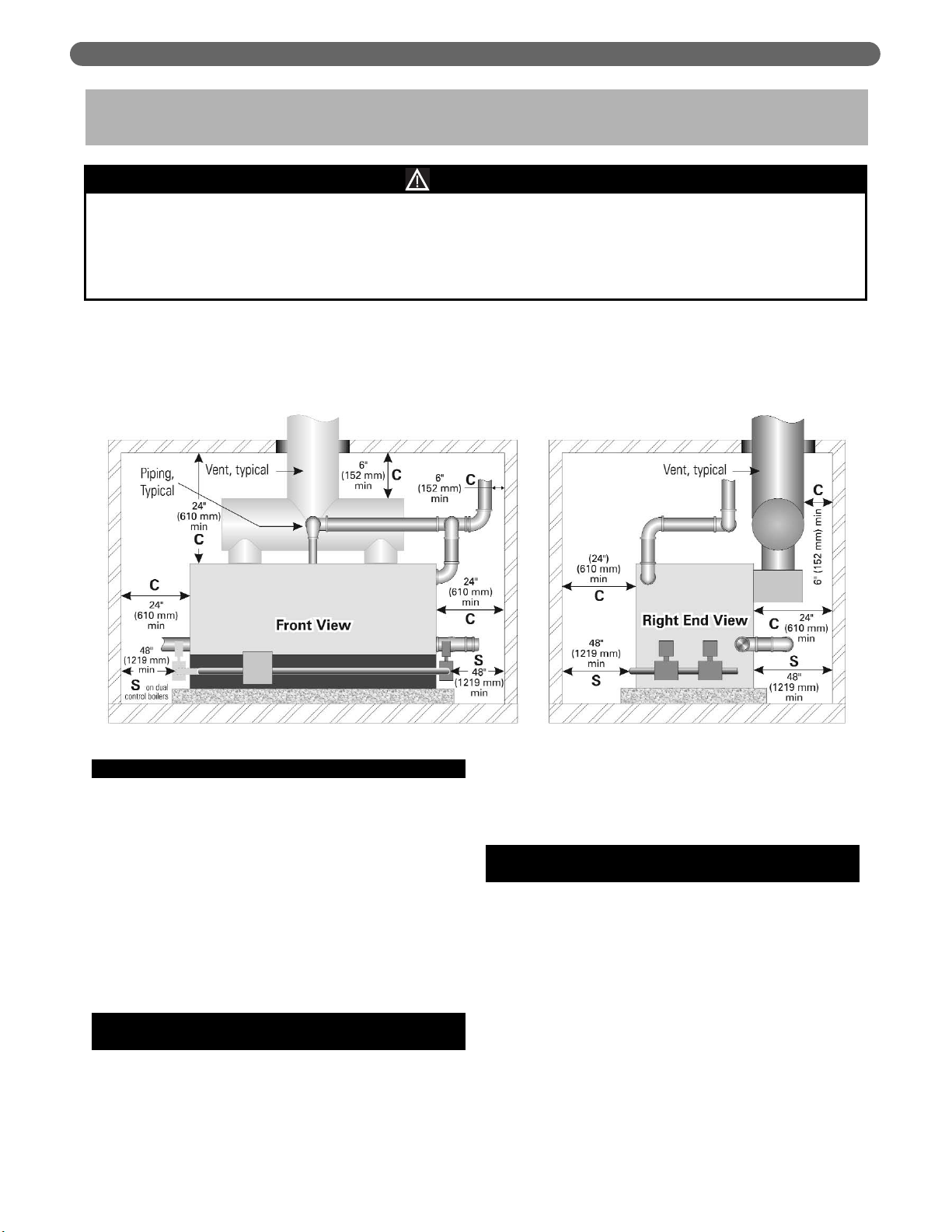
c. See Figure 1.1. Clearances with an “S” are
minimum clearances for service accessibility.
B. COMBUSTIBLE CONSTRUCTION
CLEARANCES
1. This boiler is design certified for the following
clearances to combustible construction.
• 24" (610 mm) between the front, top, sides and
rear of the jacket
• 6" (152 mm) from steam and hot water pipes
• 6" (152 mm) from vent connector
• See Figure 1.1. Clearances with a “C” indicate
minimum clearances from combustible
construction.
C. AIR FOR COMBUSTION AND
VENTILATION
1. Adequate combustion air and ventilation air must be
provided for this appliance in accordance with the
section of the National Fuel Gas Code entitled, “Air
for Combustion and Ventilation” or applicable
provisions of the local building code. Subsections 2
through 8 as follows are based on the National Fuel
Gas Code requirements.
1. PREINSTALLATION
The equipment shall be installed with those installation requirements of the authority having jurisdiction or, in the
absence of such requirements, to the current edition of the
National Fuel Gas Code
, ANSI Z223.1/NFPA 54 and/or
CAN/CGA B149 Installation Codes.
Where required by the authority having jurisdiction, the installation must conform to
American Society of
Mechanical Engineers Safety Code for Controls and Safety Devices for Automatically Fired Boilers,
ASME CSD-1.
NOTICE
Read these instructions carefully before beginning the installation.
Study the control folder and consult drawings.
A shipping list is enclosed with each boiler, listing the items packed at the factory. Check the list as you unpack parts. If any parts
are missing or damaged, report the problem to the delivering carrier immediately.
Figure 1.1: Clearance Requirements
3
PREINSTALLATION
2. Required Combustion Air Volume: The total required
volume of indoor air is to be the sum of the required
volumes for all appliances located within the space.
Rooms communicating directly with the space in
which the appliances are installed and through
combustion air openings sized as indicated in
Subsection 3 are considered part of the required
volume. The required volume of indoor air is to be
determined by one of two methods.
a. Standard Method: The minimum required
volume of indoor air (room volume) shall be 50
cubic feet per 1000 BTU/Hr (4.8 m
3
/kW). This
method is to be used if the air infiltration rate is
unknown or if the rate of air infiltration is known
to be greater than 0.6 air changes per hour. As
an option, this method may be used if the air
infiltration rate is known to be between 0.6 and
0.4 air changes per hour. If the air infiltration rate
is known to be below 0.4 then the Known Air
Infiltration Rate Method must be used. If the
building in which this appliance is to be installed
is unusually tight, PB Heat recommends that the
air infiltration rate be determined.
b. Known Air Infiltration Rate Method:
Where the air infiltration rate of a structure is
known, the minimum required volume of indoor
air for appliances other than fan assisted and
for the Series 211A Boiler shall be determined
as follows:
where:
I
other
= Input of appliances other than fan
assisted in Btu/hr
ACH = air change per hour (percent of the
volume of the space exchanged per
hour, expressed as a decimal)
For fan assisted appliances, calculate the required
volume of air using the following equation:
I
fan
= Input of the fan assisted appliances in
Btu/hr
Note: These calculations are not to be used for
infiltration rates greater than 0.60 ACH.
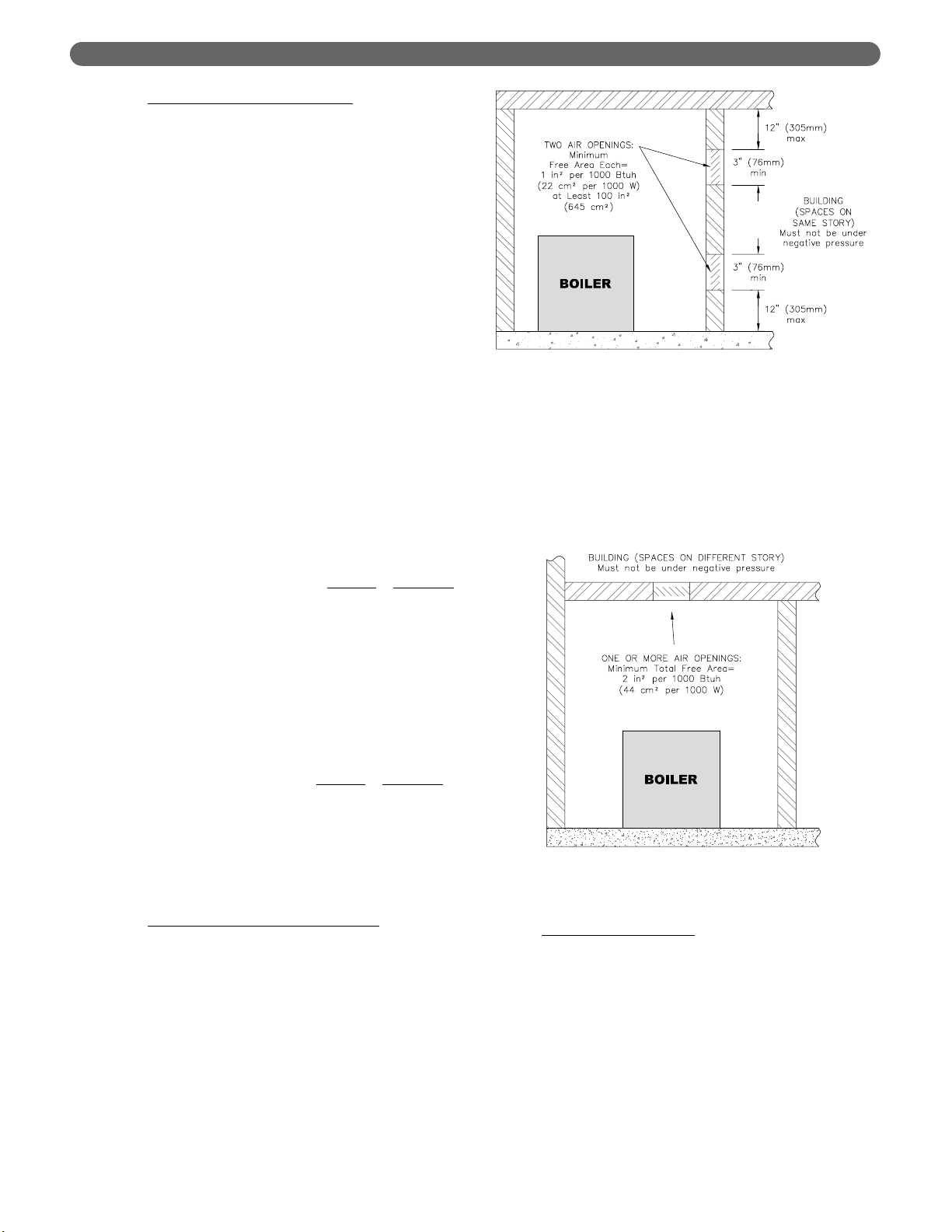
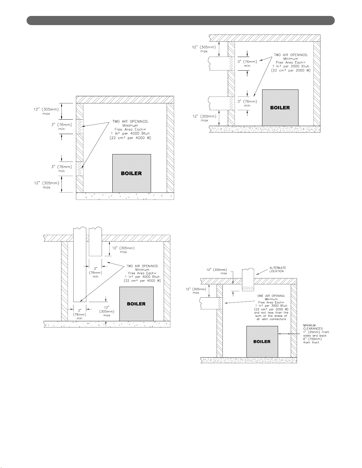
3. Indoor Air Opening Size and Location:
Openings
connecting indoor spaces shall be sized and located
as follows:
a. Combining spaces on the same floor:
Provide two permanent openings communicating
with additional spaces that have a minimum free
area of 1 in
2
per 1000 Btu/hr (22 cm2per 1000 W)
of the total input rating of all gas fired equipment
but not less than 100 in
2
(645 cm2). One
opening is to begin within 12 inches (305 mm)
from the top of the space and the other is to
begin within 12 inches (305 mm) from the floor.
The minimum dimension of either of these
openings shall be 3 inches (76 mm). See Figure
1.2 for an illustration of this arrangement.
b. Combining spaces on different floors:
Provide one or more permanent openings
communicating with additional spaces that have
a total minimum free area of 2 in
2
per 1000
Btu/hr (44 cm
2
per 1000 W) of total input rating
of all equipment. See Figure 1.3 for an
illustration of this arrangement.
4. Outdoor Combustion Air:
Outdoor combustion air is
to be provided through one or two permanent
openings. The minimum dimension of these air
openings is 3 inches (76 mm).
a. Two Permanent Opening Method: Provide
two permanent openings. One opening is to
begin within 12 inches (305 mm) of the top of
the space and the other is to begin within 12
inches (305 mm) of the floor. The openings are
to communicate directly or by ducts with the
outdoors or with spaces that freely communicate
with the outdoors. The size of the openings shall
be determined as follows:
21 ft
3
I
other
ACH 1000
Btu
/
hr
Required Volume
other
=
⎛
⎜
⎝
⎛
⎜
⎝
15 ft
3
I
fan
ACH 1000
Btu
/
hr
Required Volume
fan
=
⎛
⎜
⎝
⎛
⎜
⎝
Figure 1.2: Air Openings – All Air from Indoors
on the Same Floor
Figure 1.3: Air Openings – All Air from Indoors
on Different Floors
4
i. Where communicating directly or through
vertical ducts with the outdoors each opening
shall have a minimum free area of 1 in
2
per
4000 Btu/hr (22 cm
2
per 4000 W) of total
input rating for all equipment in the space.
See Figure 1.4 for openings directly
communicating with the outdoors or Figure
1.5 for openings connected by ducts to the
outdoors.
ii. Where communicating with the outdoors
through horizontal ducts, each opening shall
have a minimum free area of 1 in
2
per 2000
Btu/hr (22 cm
2
per 2000 W) of total rated
input for all appliances in the space. See
Figure 1.6.
b. One Permanent Opening Method: Provide
one permanent opening beginning within 12
inches (305 mm) of the top of the space. The
opening shall communicate directly with the
outdoors, communicate through a vertical or
horizontal duct, or communicate with a space
that freely communicates with the outdoors.
The opening shall have a minimum free area of
1 in
2
per 3000 Btu/hr of total rated input for all
appliances in the space and not less than the
sum of the cross-sectional areas of all vent
connectors in the space. The gas-fired equipment
shall have clearances of at least 1 inch (25 mm)
from the sides and back and 6 inches (150 mm)
from the front of the appliance. See Figure 1.7
for this arrangement.
Figure 1.4: Air Openings – All Air Directly from
Outdoors
Figure 1.5: Air Openings – All Air from Outdoors
through Vertical Ducts
Figure 1.6: Air Openings – All Air from Outdoors
through Horizontal Ducts
Figure 1.7: Air Openings – All Air from Outdoors
through One Opening
PREINSTALLATION

5
5. Combination Indoor and Outdoor Combustion Air: If
the required volume of indoor air exceeds the
available indoor air volume, outdoor air openings or
ducts may be used to supplement the available
indoor air provided:
a. The size and location of the indoor openings
comply with Subsection 3.
b. The outdoor openings are to be located in
accordance with Subsection 4.
c. The size of the outdoor openings are to be sized
as follows:
where:
A
req
= minimum area of outdoor openings.
A
full
= full size of outdoor openings calculated
in accordance with Subsection 4.
V
avail
= available indoor air volume
V
req
= required indoor air volume
6. Engineer
ed Installations: Engineered combustion air
installations shall provide an adequate supply of
combustion, ventilation, and dilution air and shall be
approved by the authority having jurisdiction.
7. Mechanical Combustion Air Supply
:
a. In installations where all combustion air is
provided by a mechanical air supply system, the
combustion air shall be supplied from the
outdoors at the minimum rate of 0.35 ft
3
/min per
1000 Btu/hr (0.034 m
3
/min per 1000 W) of the
total rated input of all appliances in the space.
b. In installations where exhaust fans are installed,
additional air shall be provided to replace the
exhaust air.
c. Each of the appliances served shall be
interlocked to the mechanical air supply to
prevent main burner operation when the
mechanical air supply system is not in operation.
d. In buildings where the combustion air is provided
by the mechanical ventilation system, the system
shall provide the specified combustion air rate in
addition to the required ventilation air.
8. Louvers & Grills:
a. The required size of openings for combustion,
ventilation, and dilution air shall be based on the
net free area of each opening.
i. Where the free area through a louver or grille
is known, it shall be used in calculating the
opening size required to provide the free area
specified.
ii. Where the free area through a louver or grille
is not known, it shall be assumed that wooden
louvers will have 25% free area and metal
louvers and grilles will have 75% free area.
iii. Nonmotorized dampers shall be fixed in the
open position.
b. Motorized dampers shall be interlocked with the
equipment so that they are proven in the full
open position prior to ignition and during
operation of the main burner.
i. The interlock shall prevent the main burner
from igniting if the damper fails to open
during burner startup.
ii. The interlock shall shut down the burner if
the damper closes during burner operation.
9. Combustion Air Ducts
a. Ducts shall be constructed of galvanized steel or
an equivalent corrosion- resistant material.
b. Ducts shall terminate in an unobstructed space,
allowing free movement of combustion air to the
appliances.
c. Ducts shall serve a single space.
d. Ducts shall not serve both upper and lower
combustion air openings where both such
openings are used. The separation between ducts
serving upper and lower combustion air
openings shall be maintained to the source of
combustion air.
e. Ducts shall not be screened where terminating in
an attic space.
f. Horizontal upper combustion air ducts shall not
slope downward toward the source of the
combustion air.
g. The remaining space surrounding a chimney
liner, gas vent, special gas vent, or plastic piping
installed within a masonry, metal, or factory built
chimney shall not be used to supply combustion
air.
h. Combustion air intake openings located on the
exterior of buildings shall have the lowest side of
the combustion air intake opening at least 12
inches (305 mm) above grade.
D. CHIMNEY OR VENT
1. Inspect the existing chimney or vent system. Make
sure it is in good condition. Inspect chimney liner
and repair or replace if necessary.
2. The vent system and installation must be in
accordance with the current edition of the National
Fuel Gas Code, ANSI Z223.1/NFPA 54, under
“Venting of Equipment”, or CAN/CGA B149,
Installation codes, under “Venting Systems and Air
Supply for Appliances”, or applicable provisions of
the local building codes.
PREINSTALLATION
V
avail
1 –
V
req
A
req
= A
full
⎛
⎜
⎝
⎛
⎜
⎝
6
PREINSTALLATION
3. Chimney/Vent Operation: The vent system must be
sized and installed to provide the draft needed to
remove all combustion products. If the vent system
does not provide enough draft, combustion products
will spill into the building from the draft hood relief
opening. If spillage of combustion products occurs,
check the vent system, the combustion and
ventilation openings and make sure the boiler room
is never under negative pressure.
4. Exterior Vents
a. If the vent is outside, make sure it is insulated
sufficiently to ensure adequate draft.
5. Vent Sizing:
a. Individual vents: Use vent piping the same
diameter as the boiler vent connection. The
minimum height is 10 feet (305 cm) above the
bottom of the draft hood (relief opening). The
vent must also extend above the roof or any
obstructions as outlined in the current edition of
the National Fuel Gas Code, ANSI Z223.1/NFPA
54 and/or CAN/CGA B149, Installation Codes or
as required by local codes.
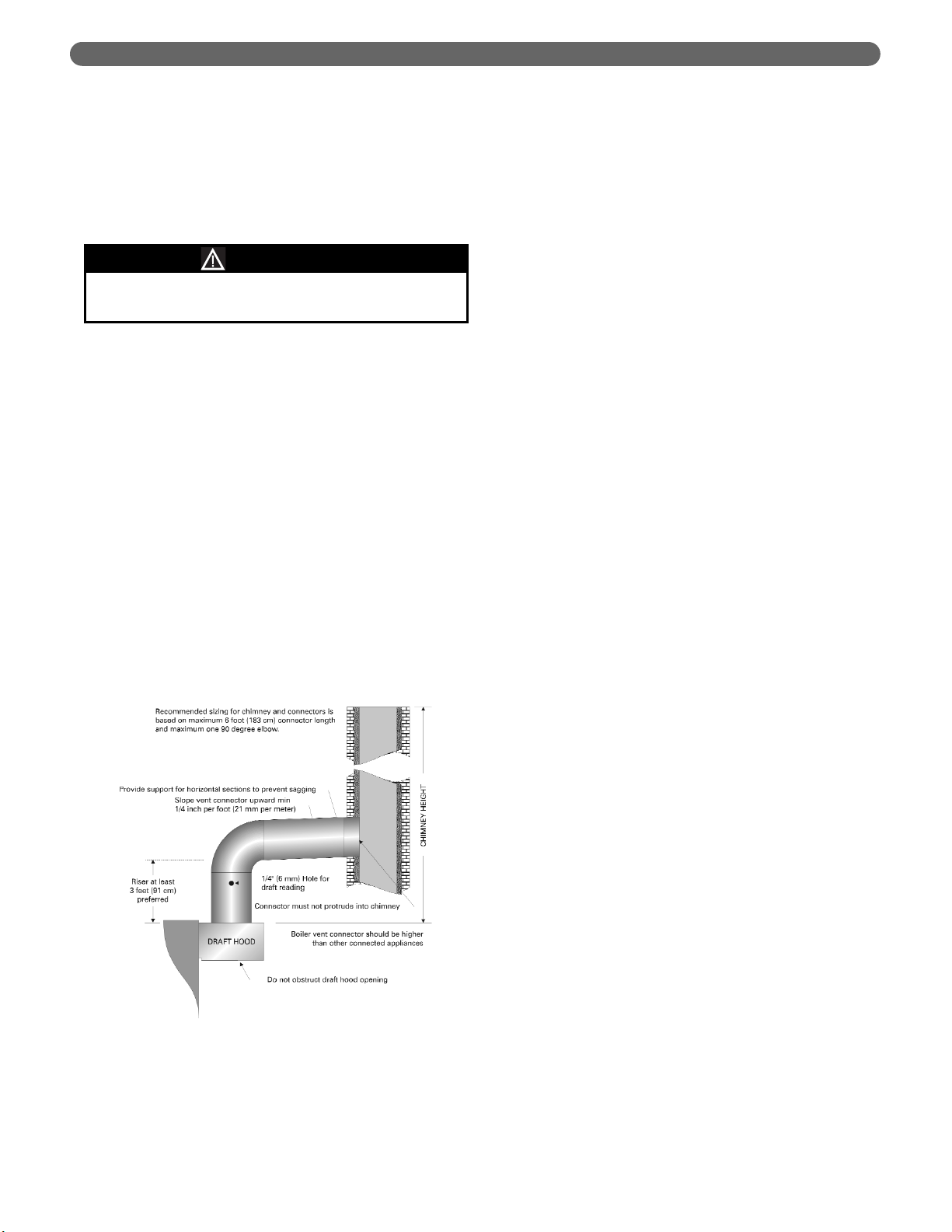
b. Combined vent breeching:
• The recommended sizing in Section 14, Boiler
Ratings & Dimensions, in this Manual is based
on a minimum chimney or vent height of 20
feet (610 cm) and a maximum horizontal run
of 6 feet (183 cm) to the chimney with no
more than one 90-degree standard elbow.
• The minimum area of the chimney serving
two or more appliances must be at least the
area of the largest chimney connector plus
50% of the total area of all other appliance
connectors.
• The vent connector must be single wall steel
or Type B double wall vent pipe. The vent
connector must be Type B double wall if it is
located in or passes through cold areas. The
vent connector must extend into, but not
beyond, the inside wall of the chimney.
6. Vent Connection to Boiler (Figure 1.8):
a. Provide at least a 3 foot (91 cm) rise in the vent
connection on the boiler.
b. The vent system should provide a draft of at least
0.02" w.c. (5 Pa) measured at the vent
connections.
c. Support the weight of the vent system
independently of the boiler draft hood. The draft
hood is not designed to carry structural loading.
d. Provide support of the vent connector
(breeching) at maximum 12 foot (366 cm)
intervals to prevent sagging and to provide a
minimum upward slope of 1/4" per foot (21 mm
per meter).
e. Do not connect the vent for this boiler into any
vent system which operates with positive
pressure.
f. Use Type B double-wall pipe for vents which run
through unheated spaces.
7. Removing an existing boiler from a common vent: At
the time for removal of an existing boiler, the
following steps shall be followed with each appliance
connected to the common venting system placed in
operation, while the other appliances remaining
connected to the common venting system are not in
operation.
a) Seal any unused openings in the common
venting system.
b. Visually inspect the venting system for proper size
and horizontal pitch and determine there is no
blockage or restriction, leakage, corrosion and
other deficiencies which could cause an unsafe
condition.
c. Insofar as is practical, close all building doors
and windows and all doors between the space in
which the appliances remaining connected to the
common venting system are located and other
spaces of the building. Turn on clothes dryers
and any appliance not connected to the common
venting system. Turn on any exhaust fans, such
as range hoods and bathroom exhausts, so they
will operate at maximum speed. Do not operate
a summer exhaust fan. Close fireplace dampers.
d. Place in operation the appliance being inspected.
Follow the lighting instructions. Adjust the
thermostat so appliance will operate continuously.
e. Test for spillage at the draft hood relief opening
after 5 minutes of main burner operation. Use
the flame of a match or candle, or smoke from a
cigarette, cigar or pipe.
Failure to provide adequate venting can result in
severe property damage, personal injury or death.
WARNING
Figure 1.8: Vent Connection
7
PREINSTALLATION
f. After it has been determined that each appliance
remaining connected to the common venting
system properly vents when tested as outlined
above, return doors, windows, exhaust fans,
fireplace dampers and any other gas-burning
appliance to their previous condition of use.
g. Any improper operation of the common venting
system should be corrected so the installation
conforms with the current edition of the National
Fuel Gas Code, ANSI Z223.1/NFPA 54 and/or
CAN/CGA B149, the common venting system
should be resized to approach the minimum size
as determined using the appropriate tables
located in the chapter Sizing of Category I
Venting Systems in the current edition of the
National Fuel Gas Code, ANSI Z223.1/NFPA 54
and/or CAN/CGA B149, Installation Codes.
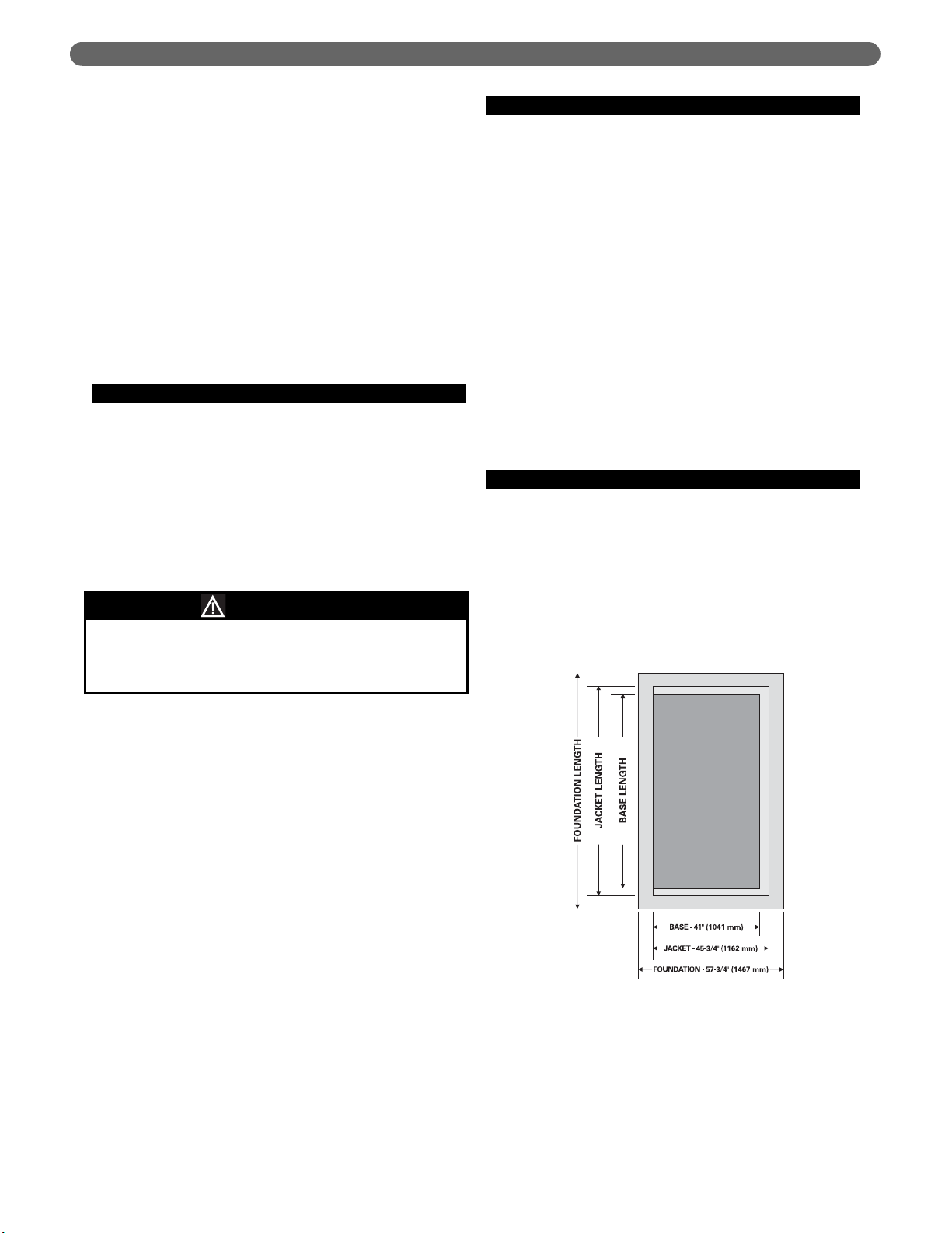
E. BOILER SETTING
1. Provide a good, level foundation for the boiler with
the minimum dimensions given in Table 1.1. The
flooring and structural support system must be
suitable for the operating weight of the boiler and
any connected piping.
2. Do not operate the boiler until the foundation, if new
concrete, has thoroughly cured. The high
temperature under the burners could cause major
damage to the concrete if it still contains moisture.
3. If the boiler is installed in a penthouse or if wiring of
any sort is run underneath the boiler foundation,
construct the foundation with provision for air flow
underneath between the main floor and the top of
the boiler foundation.
a. Concrete block aligned with the openings
connected continuously would serve this
purpose, for example.
b. If the foundation must be a concrete slab, use an
air cell high temperature insulating board, at least
1/2 inch (13 mm) thick, with aluminum backing,
aluminum side up. 1/2 inch (13 mm) Hi Temp
millboard with aluminum backing would be
acceptable as well. Place the insulating board on
the slab inside the base.
F. WATER QUALITY AND MAKE-UP
1. Check the system to make sure there are no leaks or
overfilling problems which might cause excessive
make-up water to be added. Make-up water causes
liming in the boiler and brings in oxygen. Oxygen
can cause severe damage to the boiler through
oxygen corrosion pitting.
2. Make sure the expansion tank and automatic fill
valve (if used) are operating correctly. If either of
these causes high pressure in the system, the boiler
relief valve will weep or open, allowing fresh water to
enter the system.
3. Make sure the system controls don’t subject the
boiler to excessively low water temperatures, which
would cause condensation of flue gases and
corrosion of the boiler.
4. Do not use chemicals or substances in the
boiler or system which contain petroleum or its
derivatives. This will damage the boiler seals.
G. INSTALLATION SURVEY
For new and existing installations, a Water Installation
Survey is available from PB Heat, LLC. The survey will
provide information on how a water boiler works with
your specific system and will provide an overview of
water system operation in general.
You can also use this survey to locate system problems
which will have to be corrected. To obtain copies of the
Water Installation Survey, contact your PB Heat
representative or download it from PeerlessBoilers.com.
Do not install this boiler on carpeting or any
combustible flooring. A significant fire hazard could
result, with potential for property damage, personal
injury or death.
WARNING
Figure 1.9: Foundation Layout

8
PREINSTALLATION
Boiler
Boiler Base Length Jacket Length Foundation Length
Model inches
mm inches mm inches mm
211A-04 22-1/2 572 28-1/8 714 40-1/8 1019
211A-05 28-1/8 714 33-3/4 857 45-3/4 1162
211A-06 33-3/4 857 39-3/8 1000 51-3/8 1305
211A-07 39-3/8 1000 45 1143 57 1448
211A-08 45 1143 50-5/8 1286 62-5/8 1591
211A-09 50-5/8 1286 56-1/4 1429 68-1/4 1734
211A-10 56-1/4 1429 61-7/8 1572 73-7/8 1876
211A-11 61-7/8 1572 67-1/2 1714 79-1/2 2019
211A-12 67-1/2 1714 73-1/8 1857 85-1/8 2162
211A-13 73-1/8 1857 78-3/4 2000 90-3/4 2305
211A-14 78-3/4 2000 84-3/8 2143 96-3/8 2448
211A-15 84-3/8 2143 90 2286 102 2591
211A-16 90 2286 95-5/8 2429 107-5/8 2734
211A-17 95-5/8 2429 101-1/4 2572 113-1/4 2877
211A-18 101-1/4 2572 106-7/8 2715 118-7/8 3019
211A-19 106-7/8 2715 112-1/2 2857 124-1/2 3162
211A-20 112-1/2 2857 118-1/8 3000 130-1/8 3305
211A-21 118-1/8 3000 123-3/4 3143 135-3/4 3448
211A-22 123-3/4 3143 129-3/8 3286 141-3/8 3591
211A-23 129-3/8 3286 135 3429 147 3734
211A-24 135 3429 140-5/8 3572 152-5/8 3877
211A-25 140-5/8 3572 146-1/4 3715 158-1/4 4020
211A-26 146-1/4 3715 151-7/8 3858 163-7/8 4162
211A-27 151-7/8 3858 157-1/2 4000 169-1/2 4305
211A-28 157-1/2 4000 163-1/8 4143 175-1/8 4448
211A-29 163-1/8 4143 168-3/4 4286 180-7/8 4594
211A-30 168-3/4 4286 174-3/8 4429 186-3/8 4734
211A-31 174-3/8 4429 180 4572 192 4877
211A-32 180 4572 185-5/8 4715 197-5/8 5020
211A-33 185-5/8 4715 191-1/4 4858 203-1/4 5163
211A-34 191-1/4 4858 196-7/8 5001 208-7/8 5305
211A-35 196-7/8 5001 202-1/2 5143 214-1/2 5448
211A-36 202-1/2 5143 208-1/8 5286 220-1/8 5591
211A-37 208-1/8 5286 213-3/4 5429 225-3/4 5734
211A-38 213-3/4 5429 219-3/8 5572 231-3/8 5877
211A-39 219-3/8 5572 225 5715 237 6020
211A-40 225 5715 230-5/8 5858 242-5/8 6163
211A-41 230-5/8 5858 236-1/4 6001 248-1/4 6306
211A-42 236-1/4 6001 241-7/8 6144 253-7/8 6448
211A-43 241-7/8 6144 247-1/2 6286 259-1/2 6591
211A-44 247-1/2 6286 253-1/8 6429 265-1/8 6734
211A-45 253-1/8 6429 258-3/4 6572 270-3/4 6877
211A-46 258-3/4 6572 264-3/8 6715 276-3/8 7020
Table 1.1: Boiler Foundation Layout
9
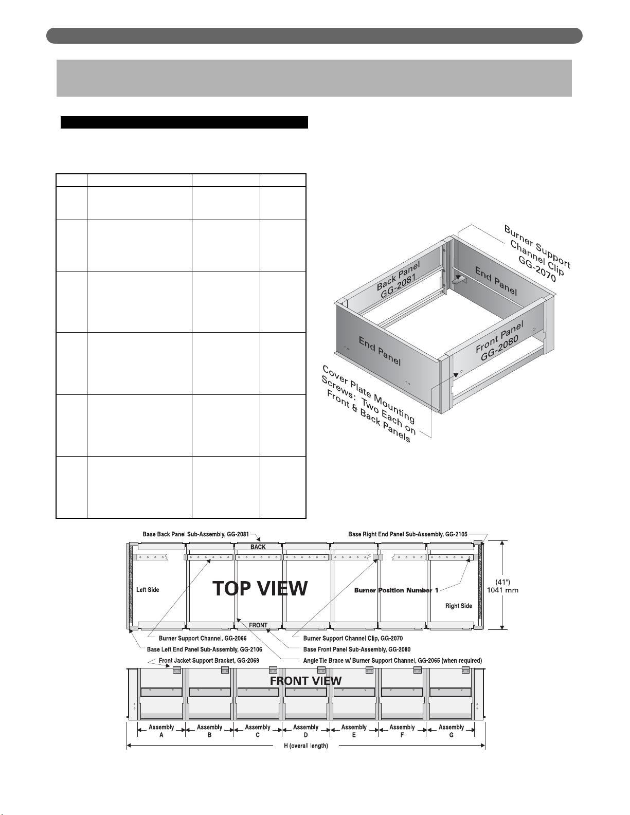
A. BASE ASSEMBLY
1. Collect the crates containing the Base Assembly
parts. Table 2.1 shows the quantity of each crate
required. The crates contain the following parts:
2. Open crate number 2. Remove the End Panels and
mount a Support Channel Clip toward the rear on
each panel as shown in Figure 2.2 using 1/4"-20 x
1/2" (13 mm) round head machine screws and 1/4"
lock washers provided.
ASSEMBLE THE BASE
2. ASSEMBLE THE BASE
2
2AA
2BB
2CC
2DD
2EE
Crate
Right End Panel Sub-Assembly
Left End Panel Sub-Assembly
Burner Support Channel Clips (2)
Front Panel Sub-Assembly
Back Panel Sub-Assembly
Burner Support Channel
Front Panel Support Bracket
Section Assembly Kit
Front Panel Sub-Assembly
Back Panel Sub-Assembly
Burner Support Channel
Angle Tie Brace
Front Panel Support Bracket
Section Assembly Kit
Front Panel Sub-Assembly
Back Panel Sub-Assembly
Burner Support Channel
Angle Tie Brace
Front Panel Support Bracket
Section Assembly Kit
Front Panel Sub-Assembly
Back Panel Sub-Assembly
Burner Support Channel
Angle Tie Brace
Front Panel Support Bracket
Section Assembly Kit
Front Panel Sub-Assembly
Back Panel Sub-Assembly
Burner Support Channel
Angle Tie Brace
Front Panel Support Bracket
Section Assembly Kit
Items
90338
90340
90341
90342
90343
90344
Sub-Assembly #
GG-2112
GG-2113
GG-2070
GG-2080
GG-2081
GG-2066
GG-2069
GG-1030
GG-2080-1
GG-2081-1
GG-2066-1
GG-2065
GG-2069
GG-1030
GG-2080-2
GG-2081-2
GG-2066-2
GG-2065
GG-2069
GG-1030-1
GG-2080-3
GG-2081-3
GG-2066-3
GG-2065
GG-2069
GG-1030-2
GG-2080-4
GG-2081-4
GG-2066-4
GG-2065
GG-2069
GG-1030-3
Par t #
Figure 2.2: Steel Base Assembly
Figure 2.1: Boiler Base Assembly
10
3. Attach the Front Panel and Back Panel (Figure 2.2) to
the Left Hand End Panel using 5/16"-18 x 1" (25 mm)
long cap screws and hex head nuts provided.
4. For 211A-04 through 211A-08 Only:
a. Complete the base assembly by attaching the
Right End Panel and setting the Burner Support
Channel on the clips.
5. For 211A-09 through 211A-46 Only:
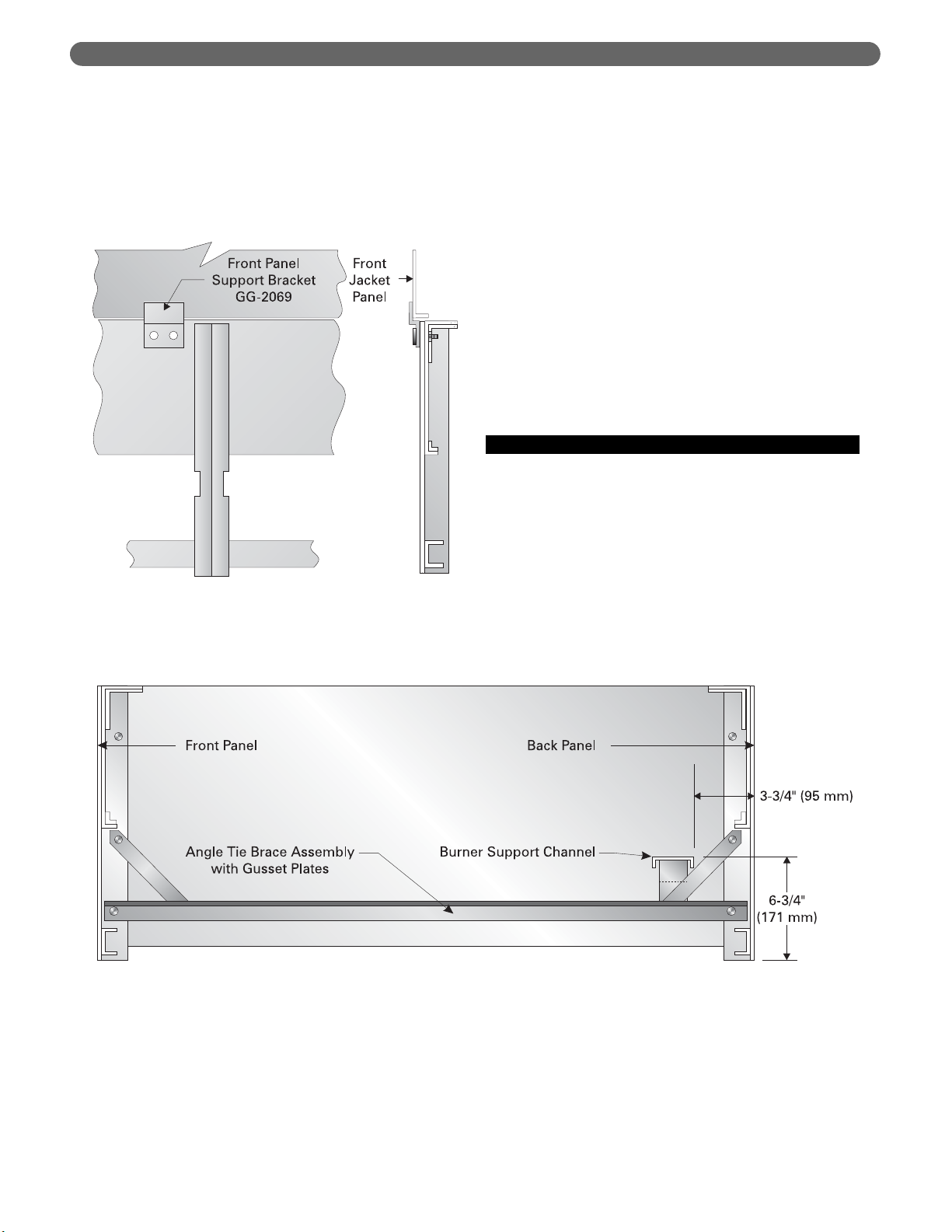
a. Attach a Front Panel Support Bracket to each
Front Panel as shown in Figure 2.4.
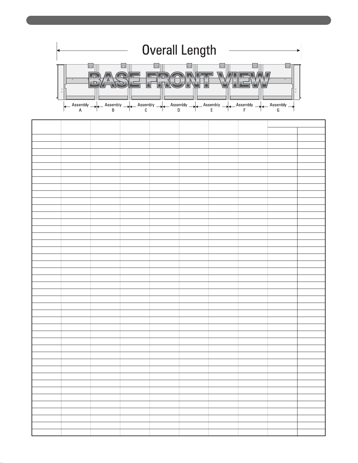
6. Bolt remaining Front and Back Panels together
using 5/16"-18 x 1" (25 mm) cap screws and hex
head nuts. See Table 2.1 for panels required. Place
the panels in the positions shown in the table and
Figure 2.1.
7. Attach an Angle Tie Brace at each panel joint to
secure the front and back panels as shown in Figure
2.3 using 5/16"-18 x 1" (25 mm) cap screws and hex
head nuts.
8. Complete the base assembly by attaching the Right
Hand End Panel using 5/16"-18 x 1" (25 mm) cap
screws and hex head nuts.
9. Set the Burner Support Channels in place as shown
in Figure 2.1.
B. INSTALL THE PILOT BURNERS
1. Check the location of the Burner Support Channels
in the Base Assembly. The dimensions should be:
a. Height above boiler foundation: 6-3/4" (171 mm)
b. Distance from back of Base: 3-3/4" (95 mm)
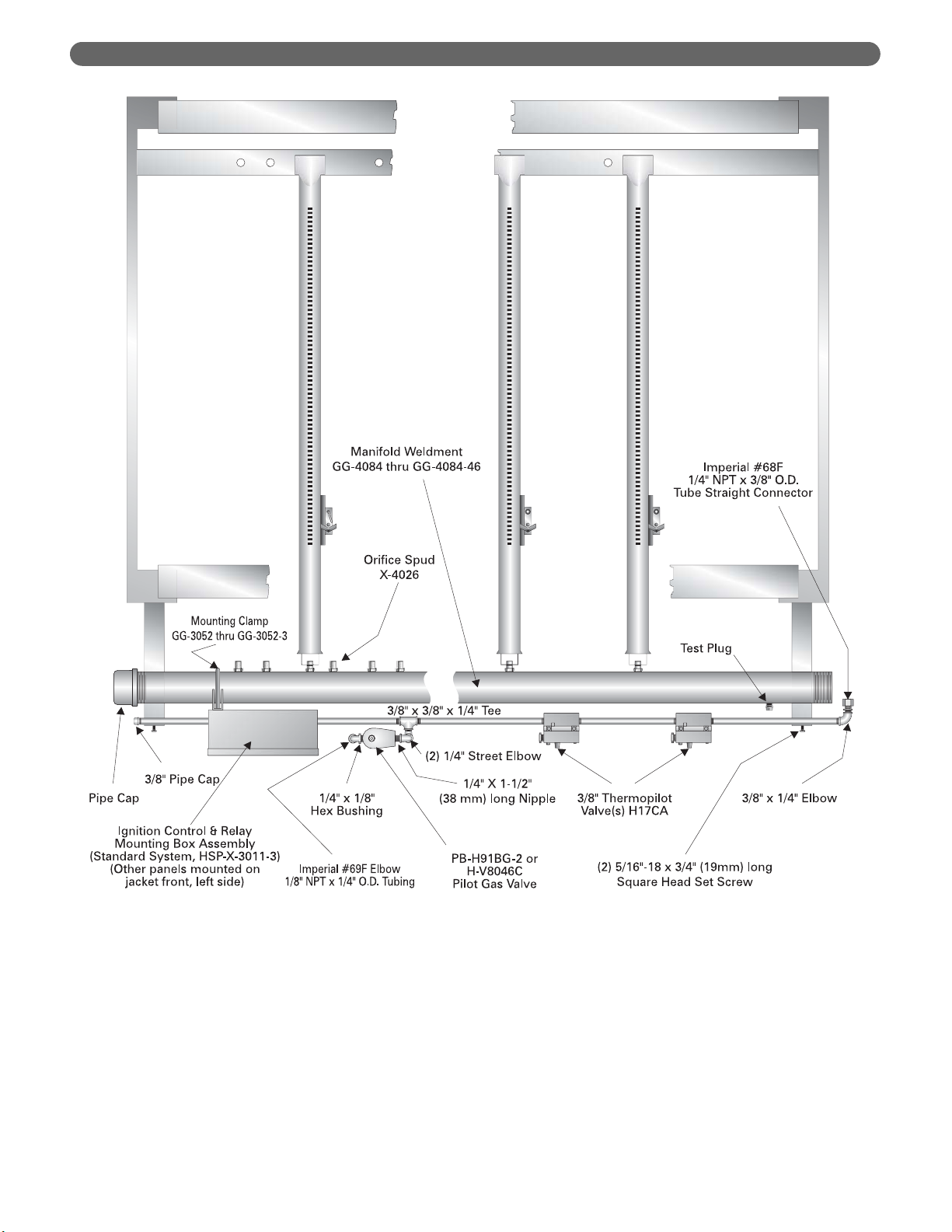
2. Remove the Gas Manifold and Pilot Line Assembly
from Box Number 7.
3. Place Manifold on front of Base. Bolt the hangers
using 5/16"-18 x 1" (25 mm) long cap screws with
5/16" flat washers. See Figure 2.5.
ASSEMBLE THE BASE
Figure 2.4: Support Bracket Installation
Figure 2.3: Angle Tie Brace Installation
11
ASSEMBLE THE BASE
Model
ABCDEFG
Number
211A-04 2AA ——————24-3/4" 629
211A-05 2BB ——————30-3/8" 771
211A-06 2CC ——————36"914
211A-07 2DD ——————41-5/8" 1057
211A-08 2EE ——————47-1/4" 1200
211A-09 2BB 2BB —————52-7/8" 1343
211A-10 2CC 2BB —————58-1/2" 1486
211A-11 2CC 2CC —————64-1/8" 1629
211A-12 2DD 2CC —————69-3/4" 1772
211A-13 2DD 2DD —————75-3/8" 1915
211A-14 2EE 2DD —————81"2057
211A-15 2EE 14A —————86-5/8" 2200
211A-16 2CC 2CC 2CC ————92-1/4" 2343
211A-17 2DD 2CC 2CC ————97-7/8" 2486
211A-18 2EE 2CC 2CC ————8'-7-1/2" 2629
211A-19 2DD 2DD 2DD ————9'-1-1/8" 2772
211A-20 2EE 2EE 2CC ————9'-6-3/4" 2915
211A-21 2EE 2EE 2DD ————10'-0-3/8" 3058
211A-22 2EE 2EE 2EE ————10'-6" 3200
211A-23 2EE 2CC 2CC 2CC — — — 10'-11-5/8" 3343
211A-24 2DD 2DD 2DD 2CC — — — 11'-5-1/4" 3486
211A-25 2EE 2EE 2CC 2CC — — — 11'-10-7/8" 3629
211A-26 2EE 2EE 2EE 2BB — — — 12'-4-1/2" 3772
211A-27 2EE 2EE 2EE 2CC — — — 12'-10-1/8" 3915
211A-28 2EE 2EE 2EE 2DD — — — 13'-3-3/4" 4058
211A-29 2EE 2EE 2EE 2EE — — — 13'-9-3/8" 4201
211A-30 2DD 2DD 2DD 2DD 2CC — — 14'-3" 4343
211A-31 2DD 2DD 2DD 2DD 2DD — — 14'-8-5/8" 4486
211A-32 2EE 2DD 2DD 2DD 2DD — — 15'-2-1/4" 4629
211A-33 2EE 2EE 14B 2EE 2EE — — 15'-7-7/8" 4772
211A-34 2EE 2EE 2EE 2EE 2CC — — 16'-1-1/2" 4915
211A-35 2EE 2EE 2EE 2EE 2DD — — 16'-7-1/8" 5058
211A-36 2EE 2EE 2EE 2EE 2EE — — 17'-0-3/4" 5201
211A-37 2DD 2DD 2DD 2DD 2DD 2DD — 17'-6-3/8" 5344
211A-38 2EE 2DD 2DD 2DD 2DD 2DD — 18'-0" 5486
211A-39 2DD 2DD 2EE 2EE 2DD 2DD — 18'-5-5/8" 5629
211A-40 2BB 2EE 2EE 2EE 2EE 2EE — 18'-11-1/4" 5772
211A-41 2EE 2EE 2DD 2DD 2EE 2EE — 19'-4-7/8" 5915
211A-42 2DD 2EE 2EE 2EE 2EE 2EE — 19'-10-1/2" 6058
211A-43 2EE 2EE 2EE 2EE 2EE 2EE — 20'-4-1/8" 6201
211A-44 2EE 2BB 2EE 2EE 2EE 2BB 2EE 20'-9-3/4" 6344
211A-45 2CC 2BB 2EE 2EE 2EE 2EE 2EE 21'-3-3/8" 6487
211A-46 2CC 2CC 2EE 2EE 2EE 2EE 2EE 21'-9" 6629
mm
Table 2.1: Base Front and Back Panel Crates
feet/inches
Overall Length
12
ASSEMBLE THE BASE
4. Place only the Burners with pilots mounted in the
locations given in Table 2.2. Install each Burner by
slipping the opening on the front of the burner over
the orifice adapter and slipping the pin on the end of
the burner into the hole in the Burner Support
Channel directly opposite the orifice.
5. Cut and fit the 1/4" aluminum tubing provided from
the pilot gas shut-off device(s) to the pilot burners.
6. Do not install the remaining burners until the Boiler
Sections are installed.
Figure 2.5: Typical Gas Manifold and Pilot Line Assembly

13
ASSEMBLE THE BASE
Table 2.2: Pilot Burner Locations – Numbered Right to Left (See Figure 2.1)
Total
Natural Gas Only Propane Gas Only
Model Number of Number Pilot Burner Locations Pilot Burner Locations
Number Pilots of (Positions Numbered Right to Left) (Positions Numbered Right to Left)
Burners
211A-04 1 6 5 — 5 —
211A-05 1 8 5 — 5 —
211A-06 1 10 5 — 5 —
211A-07 1 12 5 — 5 —
211A-08 1 14 5 — 5 —
211A-09 1 16 5 — 5 —
211A-10 1 18 5 — 7 —
211A-11 2 20 15 5 13 5
211A-12 2 22 15 5 13 5
211A-13 2 24 17 5 13 5
211A-14 2 26 17 5 9, 19 —
211A-15 2 28 19 5 9, 21 —
211A-16 3 30 25 5, 15 5, 15, 23 —
211A-17 3 32 25 5, 15 5, 15, 25 —
211A-18 3 34 25 5, 15 9, 19, 27 —
211A-19 3 36 29 5, 17 9, 21, 29 —
211A-20 3 38 35 5, 21 9, 21, 31 —
211A-21 3 40 37 5, 23 9, 23, 33 —
211A-22 3 42 19 5, 39 9, 23, 35 —
211A-23 3 44 19 5, 41 9, 23, 37 —
211A-24 3 46 21 5, 39 9, 23, 39 —
211A-25 3 48 25 5, 45 9, 23, 41 —
211A-26 4 50 19 5, 33, 47 9, 23, 33, 45 —
211A-27 4 52 21 5, 35, 49 9, 23, 35, 45 —
211A-28 4 54 23 5, 37, 51 9, 23, 35, 47 —
211A-29 4 56 27 5, 39, 53 9, 23, 39, 49 —
211A-30 4 58 29 5, 39, 51 9, 23, 39, 51 —
211A-31 4 60 31 5, 41, 53 9, 23, 39, 53 —
211A-32 4 62 33 5, 41, 59 9, 25, 41, 55 —
211A-33 4 64 35 5, 41, 61 9, 25, 41, 57 —
211A-34 5 66 35 5, 21, 49, 63 9, 23, 39, 51, 59 —
211A-35 5 68 37 5, 17, 51, 65 9, 23, 39, 51, 61 —
211A-36 5 70 37 5, 19, 53, 67 9, 23, 39, 51, 63 —
211A-37 5 72 37 5, 23, 47, 65 9, 23, 39, 51, 65 —
211A-38 5 74 25, 55 5, 43, 67
211A-39 5 76 23, 49 5, 35, 69
211A-40 5 78 25, 55 5, 33, 75
211A-41 6 80 19, 45 5, 33, 57, 77
211A-42 6 82 23, 51 5, 31, 65, 79
211A-43 6 84 23, 53 5, 33, 67, 81
211A-44 6 86 21, 55 5, 33, 67, 83
211A-45 6 88 23, 57 5, 37, 65, 85
211A-46 6 90 25, 59 5, 39, 67, 87
Electronic Pilots Standing Pilots Electronic Pilots Standing Pilots
(Spark Ignited) (Thermocouple) (Manually Lighted) (Thermocouple)
Models 211A-38 through 211A-46
Are Certified for Natural Gas Only
14
PLACE THE BOILER SECTIONS
A. PREPARATION
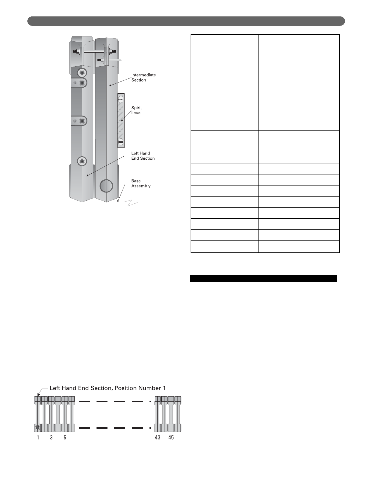
1. Check the level of the Boiler Base using a spirit level.
Make sure the base is level and that the base panels
are aligned within plus or minus 1/16" (2 mm).
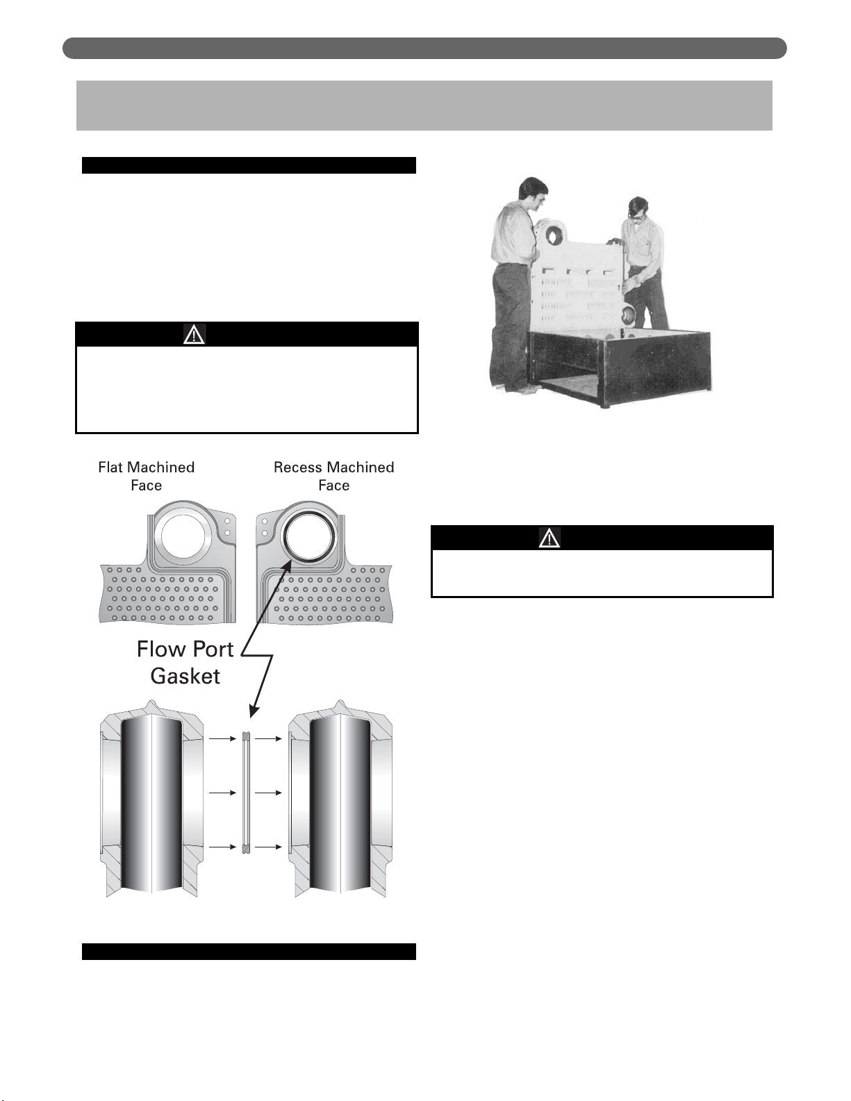
2. Check the area around the Flow Ports (Figure 3.1).
Use solvent and a clean cloth to thoroughly clean the
flat surfaces and recesses. All foreign matter must be
removed to assure a proper seal when the sections
are drawn together.
B. PLACING THE SECTIONS
1. Begin by placing the Left Hand End Section on the
left end of the base. The upper flow port goes
toward the front of the boiler as shown is Figure 3.2.
2. Slide the section to the back of the base until the cast
lug on the bottom of the section under the lower
flow port is against the base back panel. Keep the
section upright by a supporting prop or other means.
3. Align the parting line of the section with the seam
between the Base End panel and the Base Front
Panel as shown in Figure 3.3.
4. Apply Hi-Temp rope seal by spreading a thin coat of
Rope Adhesive or Spray Adhesive in the grooves on
each end of the section. Place the rope in the grooves.
Do not stretch the rope. The longer rope goes in the
front groove. NOTE: The ends of each rope must
extend 1/2" (13 mm) beyond the top and bottom.
5. Place the Flow Port Gaskets in the recesses provided
(see Figure 3.1). Do not use adhesive.
6. The following steps must be followed to insure that
no damage is done to the tie rod lugs. A 0-100 ft.-lbs.
(0-136 N
·
m) torque wrench is required.
a. Place an Intermediate Section on the base and
slide it carefully against the Left Hand End
Section.
b. Align the flow ports from front to back, as close
as possible.
c. Insert a tie rod into each of the lugs on each
section and apply a nut and washer to each end
of the tie rod.
d. Before tightening, check the vertical alignment of
the sections using a spirit level. See Figure 3.4.
Make sure they are square with the Base.
3. PLACE THE BOILER SECTIONS
Gaskets will be damaged by petroleum or its
derivatives. Completely remove all solvent residue
before placing gaskets.
Do not use petroleum based compounds in the boiler.
CAUTION
The sections are heavy and must be supported
securely.
WARNING
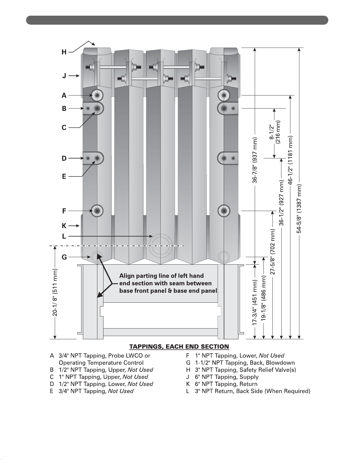
Figure 3.1: Flow Port Machining & Gasket
Figure 3.2: Placing the First Section on Base
15
PLACE THE BOILER SECTIONS
Figure 3.3: Assembling Sections on Base
16
PLACE THE BOILER SECTIONS
e. Draw sections together evenly, alternating
between top lug and bottom lug in increments of
20 ft.-lbs. (27 N
·
m). Continue until both top and
bottom lugs are tightened to 60 ft.-lbs. (81 N
·
m).
DO NOT EXCEED 60 FT.-LBS (81 N
·
m).
f. Check the level while tightening to make sure
alignment stays true. Also make sure sections
remain square with the Base from front to back
as the tie rods are tightened and as additional
sections are installed.
g. If the sections tend to run out of plumb, this will
usually be at the bottom front. Loosen the upper
nuts slightly and tighten the lower ones to adjust.
7. Assemble the remaining sections in the same way for
a finished assembly as shown in Figure 3.3.
8. Some of the Intermediate Sections have tappings for
installing additional risers from the boiler. These
Tapped Intermediate Sections must be installed as
shown in Figure 3.5A. The placement order is left to
right (Figure 3.5).
9. After all sections are mounted, apply the furnace
cement provided between the Base and the bottoms
of the sections.
C. HYDROSTATIC TEST THE BOILER
1. The supply and return piping can be permanently
erected before applying the Boiler Jacket if the pipe
nipples applied to the boiler tappings are long
enough to clear the jacket.
2. Install a drain cock in one of the tappings provided
at the bottom rear of each end section.
3. Provide a water supply line to the boiler.
4. Plug all open tappings in the boiler.
5. Provide a means to vent air as the boiler fills.
6. Fill the boiler with water, venting air as water level
rises.
7. Pressurize boiler to:
• 75 psig (517 kPa) for 50 psig (345 kPa) sections.
Do not exceed this pressure.
• 120 psig (827 kPa) for 80 psig (552 kPa)
sections. Do not exceed this pressure.
a. Maintain pressure while checking all joints and
fittings for leaks.
b. After inspection is complete, drain the boiler and
remove plugs from tappings that are to be used.
211A-29
211A-30
211A-31
211A-32
211A-33
211A-34
211A-35
211A-36
211A-37
211A-38
211A-39
211A-40
211A-41
211A-42
211A-43
211A-44
211A-45
211A-46
Boiler Model Number
Place Tapped Intermediate
Sections at Positions
(Numbered Left to Right)
10, 20
11, 21
10, 22
11, 23
13, 25
9, 17, 26
9, 18, 27
13, 21, 29
13, 21, 29
12, 22, 31
12, 20, 28
8, 16, 25, 33
12, 19, 26, 34
12, 20, 27, 35
7, 14, 22, 30, 37
8, 16, 23, 29, 37
7, 14, 21, 32, 39
7, 14, 22, 29, 36, 43
Figure 3.5: Section Positioning Numbering
Figure 3.5A: Section Position Numbering
Figure 3.4: Align Sections Vertically
 Loading...