

Page 1
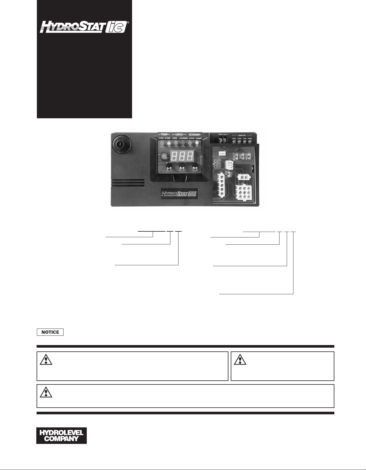
INSTALLATION INSTRUCTIONS
and OPERATING MANUAL
4200 SERIES
Multi-Function
Gas Boiler Control
120 VAC Input / 24 VAC Burner Circuit
PATENT NO. 8,931,708; 8,844,834;
7,891,572; others pending
Five Function Control
• Ignition – Intermittent Spark Ignition with single rod flame sensing
• Temperature Limit Control
• Low Water Cut-Off
• Boiler Temperature Reset
• Two Zone – Circulator outputs for DHW or second heating zone
Optional primary/secondary operation
Available for atmospheric or induced draft boilers.
See model designations below.
MODEL NUMBERS
PART NUMBERS
MODEL 4200a
Series
Vent Option
a = Atmospheric
i = induced
Mounting
Blank = Internal
X = External
Read these instructions completely before proceeding with the installation and retain instructions for future reference.
WARNING
or servicing control. Only qualified personnel may install or service this control in accordance
with local codes and ordinances. Read instructions completely before proceeding.
Electrical shock hazard. To prevent electrical shock, death or
equipment damage, disconnect power supply before installing
Series
Vent Option
0 = Atmospheric
1 = Induced
Sensor
0 = 12" Sensor
1 = 24" Sensor
2 = 48" Sensor
Mounting
Blank = Internal
X = External
48-4200
CAUTION
should be thoroughly cooled before installing or
servicing control.
To prevent serious
burns, boiler
WARNING
is recommended for unattended dwellings in climates subject to sustained below-freezing temperatures.
Frozen pipes/water damage. Central heating systems are prone to shut down as a result of power or fuel outages,
safety related fault conditions or equipment failure. Installation of freeze protection monitoring or other precautions
126 Bailey Road, North Haven, CT 06473 • Phone (203) 776-0473 • FAX (203) 764-1711 • www.hydrolevel.com
Page 2
IMMERSION WELLS
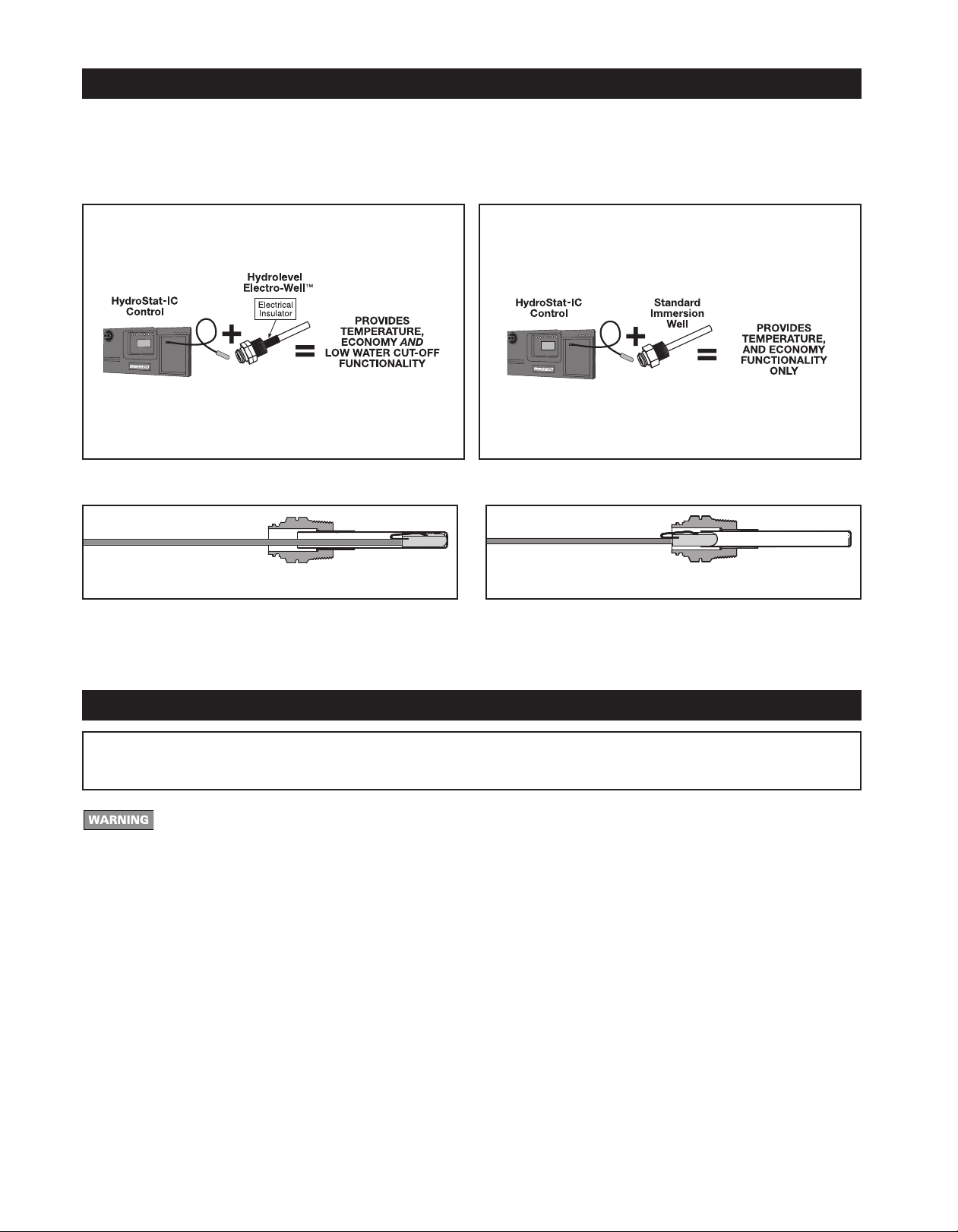
HydroStat-IC can be installed with an existing immersion well already in the boiler or with a Hydrolevel Electro-Well™
(sold separately). The low water cut-off function is automatically activated when installed with an Electro-Well™.
IMPORTANT: The control will not provide low water cut-off protection when installed with a standard immersion well.
NOTE: Do not use heat-conducting grease.
HydroStat-IC installed
with Hydrolevel Electro-Well™
IMPORTANT: For proper operation of the low water cut-off function, there
must be a minimum of ½" clearance between the copper well tube and any
surface within the boiler.
See Electro-Well models on page 15.
IMPORTANT – Sensor must be inserted all the way into the well for proper operation.
NOTE: When installed on a standard immersion well, the “LWCO Active” LED
will not illuminate.
HydroStat-IC installed
with standard immersion well
CORRECT INCORRECT
NOTE: In the case of space restrictions, the HydroStat-IC control may be mounted in a vertical orientation without any loss of function. Hydrolevel recommends horizontal mounting, when possible, for proper orientation of LED display.
REPLACING THE CONTROL
IMPORTANT Make sure that the immersion well or Electro-Well™ is installed in the boiler manufacturer’s designated
temperature limit control tapping.
NOTE:
If installing an Electro-Well, pipe sealing compound should be used. Teflon tape is not recommended.
All work must be performed by a qualified and licensed professional in accordance with all
applicable codes and ordinances.
1 Turn off power to the system.
2 Unplug the line voltage connection, circulator connector, transformer connector, damper connector,
low voltage connector, and ignition wire from the existing control. See Figure 1 next page.
Note: When replacing a Honeywell control with Envirocom, disconnect the wires from the Envirocom
terminals and terminate safely. That feature will not be used with the new control.
3 Remove the old control from the boiler jacket and install the new control in the same mounting slots.
Note: To activate the low water cut-off feature of the new control, remove the existing immersion
well and replace it with a Hydrolevel Electro-Well.
4 Reconnect all plug connectors.
5 Insert the sensor fully into the well.
2
Page 3
WIRING
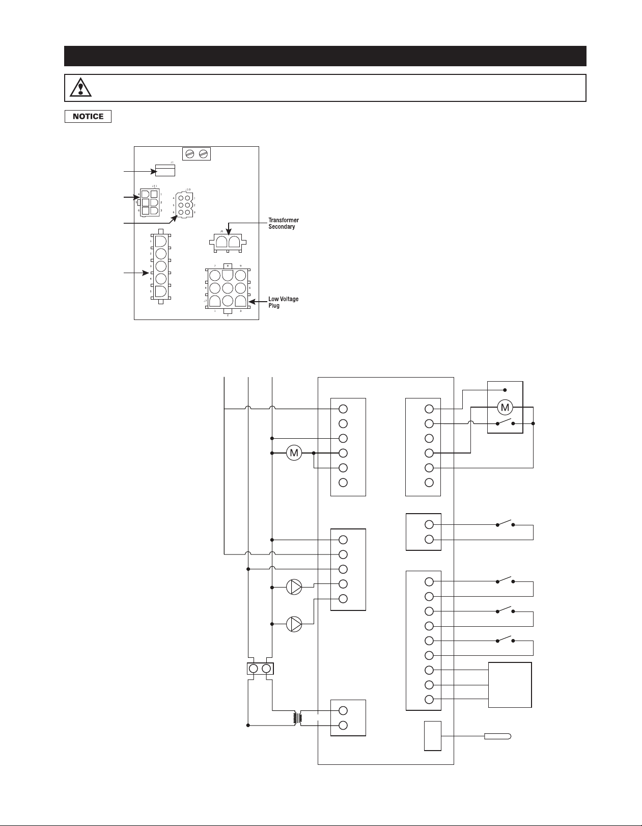
Temp/Water
Sensor
DHW or Zone 2
Line Voltage
Plug
Inducer Plug
(inducer model only)
Vent Damper Plug
(atmospheric model only)
1
3
4
6
7
9
2
5
8
1
2
3
4
5
6
1
2
3
4
5
6
1
2
3
4
5
1
2
1
2
INDUCER
INDUCER
MOTOR
(INDUCER
MODEL ONLY)
HEATING
CIRCULATOR
DHW
CIRCULATOR
GND
GND
GND
GND
GND
DHW
VENT
DAMPER
VENT DAMPER
(ATMOSPHERIC MODEL ONLY)
AIR PRESSURE SWITCH
(INDUCER MODEL ONLY)
LIMITS
DHW
THERMOSTAT
LINE
VOLTAGE
LOW
VOLTAGE
TRANSFORMER
SECONDARY
TEMP/WATER
SENSOR
TRANSFORMER
120 VAC
PLUG
4200a / 4200i
GND L1 L2
24 VAC
PV
MV
PV/MV
GAS
VALVE
WARNING
installing or servicing this control.
All wiring must comply with the National Electric Code or any other state or local codes or
regulations.
Figure 1
Electrical shock hazard. To prevent electrical shock, death or equipment damage, disconnect power supply before
*Note: When the HydroStat IC
control is programmed for primary / secondary pump operation, The "DHW circulator"
(pin 5) becomes the primary
pump and the "heating circulator" (pin 4) becomes the
secondary pump.
*
*
3
Page 4
SETTING THE CONTROL
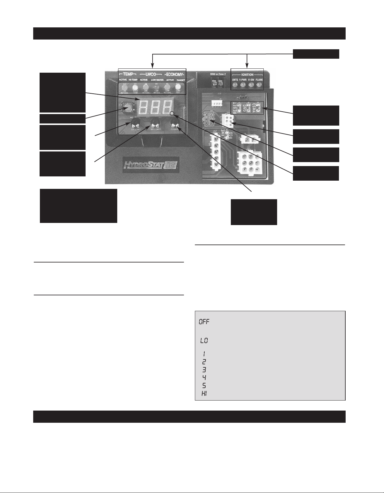
Dynamic
Display
Water Temperature
and Real Time Verifi-
cation of Setting Ad-
Test/Settings Button
(OFF or 110°-220°F)
Differentials are automatic
and will vary based on
control settings and boiler
temperature.
justments.
Low Temperature
Limit Setting
Factory: OFF
High Temperature
Limit Setting
(100°-220°F)
Factory: 190°F
Note: The high limit differential
can be adjusted when the economy feature is turned off. See
Optional Features on page 10.
Economy Dial
(OFF or LO, 1, 2, 3,
4, 5, HI)
Factory: 1
Diagnostic LEDs
Spade Connectors
for OS-100 Outdoor
Sensor Kit
Vent Damper Receptacle*
Draft Inducer Receptacle*
Indicator Light
(indicates heat
*Model specific
call)
NOTE: Settings can be checked using the
TEST/SETTINGS Button. See page 8 for details.
Setting the High Limit
The high limit is factory set at 190°F. To adjust, turn the HI
TEMP Dial
until the desired setting is displayed. (Setting
range: 100°-220°F)
Setting the Economy Feature
The Economy Feature is factory set for a 1 zone heating system. To adjust, turn the ECONOMY Dial
displayed equals the number of heating zones. Do not include
indirect water heaters in the number of heating zones. The
Economy Feature conserves fuel by reducing boiler temperature (see “How Thermal Targeting Works” below). If the heating
system is unable to supply needed heat to the house, the
ECONOMY Dial should be turned to a lower setting (example:
In a three zone house, turn the dial to 2 or 1). Conversely, if
the boiler provides adequate heat, added fuel savings can be
achieved by selecting a higher setting (example: 4 or 5). If the
heating and indirect water heater signals were not separated
when wiring the control, the Economy Feature should be
turned OFF to ensure the boiler supplies adequate temperature to heat the indirect tank.
until the number
Program/Low Limit Dial
The Program/Low Limit Dialcan be used to enter the control’s programming mode to select optional features described
on pages 10-12 of this manual. At all other times it should be
rotated fully counter-clockwise in the OFF position.
NOTE: One of the features (described on page 12) enables
the dial to be programmed for use as a Low Temperature Limit
setting. This feature should only be activated for boilers
equipped with tankless coils used for domestic hot water production.
SETTING
Disables economy function. Will allow boiler to fire until hi-
limit temp is reached and re-fire with a 10° subtractive
differential.
Provides lowest level of fuel savings. Use this setting only if
the house does not stay warm at higher settings.
Recommended setting for single zone systems
Recommended setting for Two zone systems
Recommended setting for Three zone systems
Recommended setting for Four zone systems
Recommended setting for Five zone systems
Provides highest level of fuel savings
HOW THERMAL TARGETING WORKS
Thermal Targeting technology analyzes thermostat activity and continually evaluates how much heat the house requires. When it is very cold outside, the heat demand is high and the HydroStat IC will raise the boiler’s Target temperature to provide needed heat to the home. When the outside temperature is milder, the heat demand is lower. During
these periods, the HydroStat IC will lower the boiler’s Target temperature – saving fuel – while continuing to provide
comfort to the house.
4
Page 5
IGNITION SEQUENCING AND FLAME SAFETY
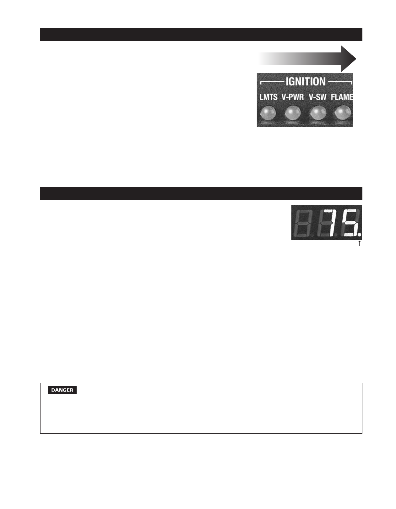
Lights come on in sequence.
The HydroStat-IC proves the safety limit devices on the boiler before igniting the pilot. As each limit is checked, the corresponding
light will turn on indicating the limit is satisfied. If any limits are not
satisfied, the corresponding light will blink and the ignition sequence
will stop. After ignition, the HydroStat-IC continues to monitor the
limit devices, vent damper or air pressure switch, and pilot flame. If
any of these are open or the pilot flame is lost, the main valve is immediately de-energized and the corresponding light will blink.
Spill
switch,
flame
roll-out
switch,
etc.
INITIATING BOILER IGNITION
Power the system and set the thermostat to call for heat. The decimal on lower
right of the temperature display will light indicating the HydroStat-IC is receiving
the call for heat. Note: The HydroStat HI-TEMP, LOW WATER, and TARGET
lights must all be off for the startup sequence to continue. If any are on, review
page 8 for more information.
Power
sent to
vent
damper
or
inducer
Decimal lights on a call for heat
Confirmation
from
vent
damper
or
inducer
Flame is
Pilot
established
1. Limit Check: The control will check all limits in the burner circuit (ex. spill switch, flame roll out switch)
prior to ignition. If all limits are satisfied, the LIMITS light will turn on and the control will proceed to check
the venting. If any limit device is not satisfied, the LIMITS light will blink and the control will not proceed
with ignition.
2. Venting Check:
• 4200a Control: Once the limits are confirmed, the control sends power to the vent damper and the
green V-PWR light comes on. When the vent damper fully opens and triggers the end switch on the
damper, the V-SW light comes on. Note: If the damper end switch does not make within 30 seconds,
the green V-SW light will blink. The startup sequence will stop until the damper end switch makes and
the green V-SW light comes on.
• 4200i Control: Once the limits are confirmed, the control sends power to the inducer motor and the
green V-PWR light comes on. When the inducer motor triggers the air pressure switch, the green VSW light comes on. Note: If the air pressure switch does not make within five seconds, the green V-
SW light will blink. The startup sequence will stop until the air pressure switch makes and the green
V-SW light comes on.
Carbon Monoxide Hazard: If the burner fires when the vent damper is not fully opened (atmospheric boilers), the inducer fan is not operating (induced draft boilers) or there is any
other blockage in the flue, dangerous flue products, such as carbon monoxide, will escape
into the living space causing severe personal injury or death. The flue as well as the vent
damper or inducer motor must be checked for proper operation before allowing the system
to operate.
Initiating Boiler Ignition continued next page
5
Page 6

INITIATING BOILER IGNITION continued
3. Pilot Ignition: Once the control receives confirmation from the vent damper or inducer fan, the control
will initiate the spark ignitor and turn on the pilot valve to light the pilot. The control will spark the pilot intermittently (approximately one second on followed by one second off) until it verifies that the pilot is lit.
Prior to each one-second spark, the display will show the number corresponding to the ignition attempt
(01, 02, 03, etc.).
Electrical Shock Hazard: The ignition circuit of the control can produce 10,000 volts
which can cause severe injury or death.
4. Pilot Flame Sense: When the pilot flame is sensed, the green FLAME light will turn on. If, after 30 ig-
nition attempts (75 seconds), the control does not sense pilot flame, the pilot valve will de-energize, the
spark trials will terminate and the green FLAME light will blink. After a five minute delay, the ignition sequence will retry to ignite the pilot (starting at step 3 above).*
5. Main Burner Ignition: When the pilot flame is sensed, the control energizes the main gas valve to fire
the boiler.
*NOTE: The five minute delay will be reset if the call for heat is removed for 45 seconds.
OPERATING CHECK
1. Check Flame Current: With the boiler in operation, press and release the TEST/SETTINGS button
four times in short intervals (see page 8 for more details). The display will show the flame current. A good
reading is 2.0 (or higher) micro amps. If the reading is not in this range, refer to PROPER PILOT FLAME
on page 9 for instructions on adjusting the pilot.
2. High Temperature Limit Check: The high limit shut-off functionality of the control must be tested following installation. On the first run cycle following the system being powered, the control will allow the
boiler to fire to the high limit setting. Thereafter, the Economy function (when active) will establish target
temperatures often below the high limit setting. To test the high limit shut-off function, recycle power to
the control prior to initiating the call for heat. NOTE: The Economy function can also be turned off prior to
testing the high limit shut-off. If this method is used, the Economy dial will need to be reset to the desired
setting following the test (see page 4 for more details).
Flame Shut Down Sequencing: When the boiler reaches the HI LIMIT setting or the call for heat goes
away, the main burner, pilot flame and FLAME light will all turn off.
• 4200a Control: The damper will begin to close and the V-PWR, V-SW, and LIMITS lights will turn off.
• 4200i Control: After 15 seconds, the inducer motor will turn off and the V-PWR, V-SW, and LIMITS
lights will turn off.
CIRCULATOR OPERATION
Circulator Hold Off Feature: To reduce the potential for condensing, on a call for heat the HydroStat-IC
will allow the boiler to heat to 125°F prior to energizing the heating circulator. Once energized, the circulator will remain on for the duration of the heating call unless the boiler temperature drops below 115°F. If
this occurs, the circulator will re-energize when the boiler returns to 125°F. Circulator Hold Off will expire
after 15 minutes. This feature can be deactivated – see page 11 for more details.
6
Page 7

2-ZONE CIRCULATOR OPTIONS
The HydroStat IC is equipped with a second zone for use with a 120 volt circulator. Unless the control is
factory installed on a boiler designed for primary/secondary heating loops, the zone will be set to function
with an indirect water heater for domestic hot water (DHW). The T-T input for this zone is the small screw
terminals labeled "DHW or Zone2". The zone output is located in the LINE VOLTAGE plug receptacle (see
page 3). Note: If the boiler’s plug connected to this receptacle does not have 5 wires, then this second
zone feature is not available. See page 11 for instructions on selecting one of the following three operating
modes.
• Domestic Hot Water (DHW): During a call from an indirect water heater, the control will allow the boiler
to fire to the high limit setting. It will prioritize the DHW call by de-energizing the heating circulator in the
event there is also a call for heat. The control will re-energize the heating circulator when the indirect
tank is satisfied or if the boiler temperature reaches 170°F. If the indirect call continues for 45 minutes,
the control will override the priority function and re-energize the heating circulator to provide space
heating.
• Zone Heating: During a call from a second zone thermostat, the control will operate the second zone
as it does the primary zone; the Economy function (when Active) will regulate the boiler temperature
and no priority will be given to either zone.
• Primary/Secondary Circulator Operation: This mode of operation should only be used for boilers or
installations utilizing a primary/secondary piping system. When the control is set in this mode, the primary circulator will be controlled by pin 5 of the LINE VOLTAGE connector (See page 3) and the secondary circulator will be controlled by pin 4. The primary pump will turn on any time there is a call for
heat, DHW, or low limit. It will remain on after the call is gone until the boiler temp drops to 120°F. The
secondary pump will turn on when there is a call for heat (T-T input) and the boiler temp is over 140°F. If
the secondary is on and the boiler temp drops below 130°F, the secondary pump will turn off. The secondary pump will not run on a call for DHW or if the control is off on warm weather shutdown. Note:
When the control is set for Primary/Secondary pump operation, program mode options 1 (Thermal PrePurge) and 5 (Circulator hold off) will default to OFF.
7
Page 8
LED LEGEND and TEST/SETTINGS BUTTON
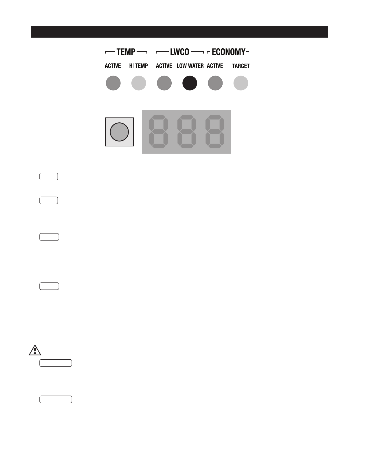
TEMP ACTIVE Indicates that the Fuel Smart
HydroStat-IC control is powered and that the temperature
function is active.
TEMP HI TEMP Illuminates when the boiler water
temperature reaches the high limit setting. It will remain lit
until the water temperature falls 10°. The HydroStat-IC
prevents burner operation while this LED is on. See
Differential explanation on page 12.
LWCO ACTIVE Indicates that the low water cut-off
(LWCO) function of the HydroStat-IC is active. When the
control is installed with a Hydrolevel Electro-Well, this LED
will be on at all times when the control is powered.
IMPORTANT: If the control is installed with a well other than
the Electro-Well, this LED will not illuminate indicating that
the control is not providing low water cut-off functionality.
LWCO LOW WATER Indicates that the boiler is in a
low water condition. The HydroStat-IC control will prevent
burner operation during this condition. If the LOW WATER
light is blinking, the control has been programmed to provide
lock-out protection in the event a low water condition is
detected (see Manual Reset Low Water Cut-Off on page 10).
Pressing the TEST/SETTINGS button will reset the control.
IMPORTANT: The system must be checked by a qualified
heating professional prior to resuming operation.
WARNING: ALLOW THE BOILER TO FULLY COOL
BEFORE ADDING WATER.
ECONOMY ACTIVE Indicates that the Thermal
Targeting function is active and the HydroStat-IC will reduce
boiler temperature to conserve fuel. The Economy feature is
activated using the ECONOMY dial. (See “How Thermal
Targeting Works” on page 4 for more information).
ECONOMY TARGET When the Economy feature is
active, the HydroStat-IC continually sets target temperatures
below the high limit setting to maximize fuel efficiency. When
the boiler water reaches the target temperature, the LED
illuminates and the burner will shut down. The boiler water
will continue to circulate and heat the house as long as the
thermostat call continues. The LED will stay lit until the boiler
temperature drops below the differential set point at which
point the boiler will be allowed to fire again. See Differential
explanation on page 12.
NOTE: This LED illuminates regularly during normal boiler
operation.
TEST/SETTINGS Button
To Test Low Water Cut-Off: Press and hold the Test/
Settings button for 5 seconds. The display will read LCO.
LWCO TEST
The red Low Water light should illuminate and the burner
circuit should de-energize. NOTE: The control must be
installed with a Hydrolevel Electro-Well for low water cut-off
functionality (see page 2 for more details).
To View Current Settings: Press and release the
Test/Settings Button in short intervals to sequentially display
the following settings:
HIGH LIMIT SETTING
LCO
0
HL
왔
LOW LIMIT SETTING LL
왔
ECONOMY SETTING ECO
0
왔
CURRENT TARGET TEMPERATURE ooo
왔
FLAME CURRENT FLA
The display will return to boiler temperature (default) if
Test/Settings Button in not pressed for 5 seconds.
NOTE: Flame Current reading will remain in the display for
30 seconds to allow for pilot adjustment
8
Page 9
IGNITION LED LEGEND and OPERATION
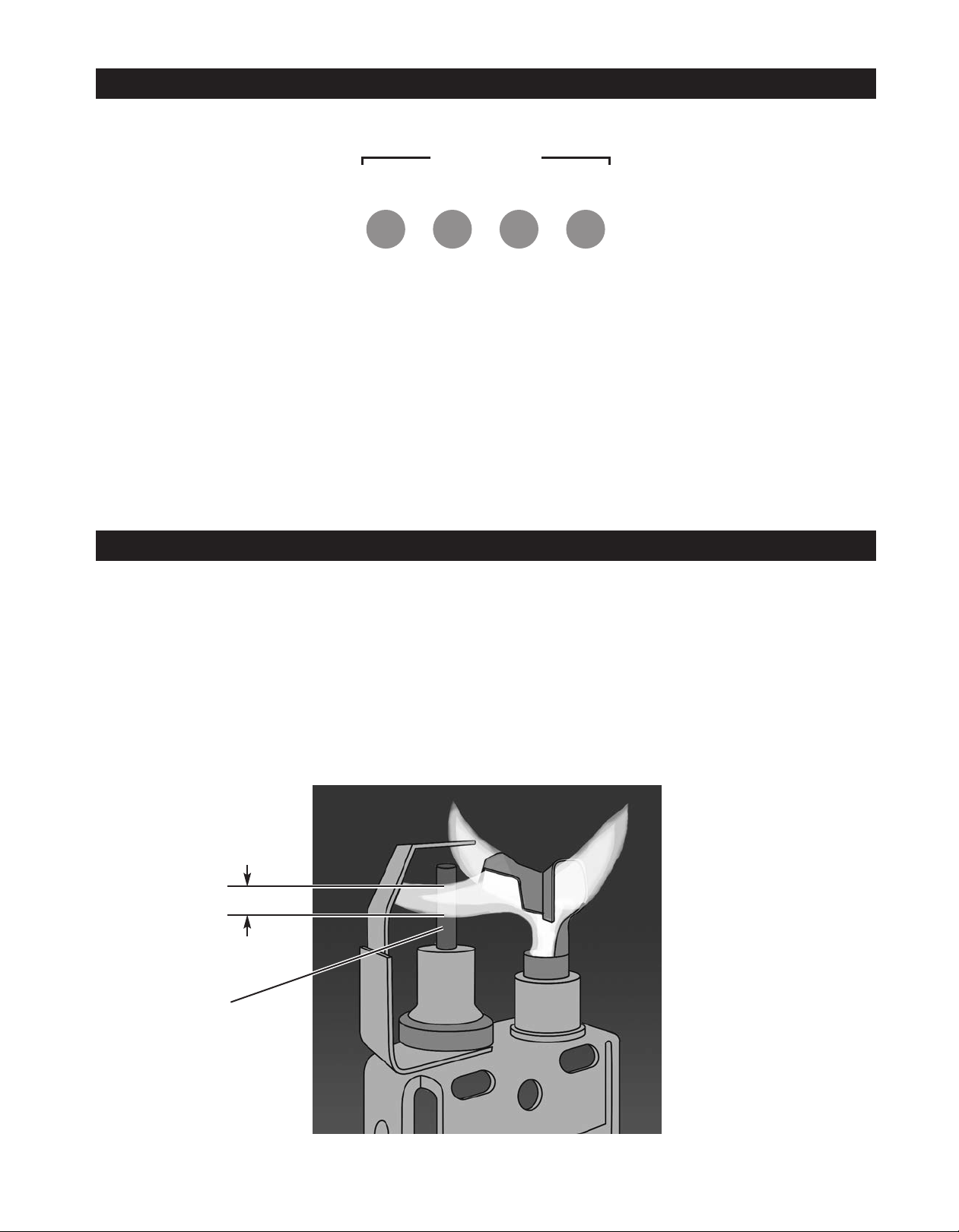
IGNITION
LIMITS V-PWR V-SW FLAME
LIMITS Illuminates on a call for heat to indicate the
external limits are satisfied. (External limits may include flame
rollout, spill switch, secondary low water cut-off etc.). If the
external limits are open, the LIMITS light will blink.
V-PWR Indicates power has been sent to the vent
damper (Model 4200a) or the inducer motor (Model 4200i).
PROPER PILOT FLAME
A properly adjusted pilot should have a blue, steady flame
with an inner cone that engulfs 3/8" - 1/2" of the flame rod.
The flame rod should glow bright orange from the heat and
the flame current should be higher than 2.0 µA.
Note: To read flame current see TEST/SETTINGS button on
page 8.
If the pilot flame is over sized, orange in color, and blowing far
beyond the flame rod then the pilot is over fired. The flame current will read outside of the nominal range and the pilot should
be adjusted down.
V-SW Illuminates when the vent damper switch (on an
atmospheric boiler) or the air pressure switch (on an induced
draft boiler) has made. If the damper end switch (Model
4200a) or the air pressure switch (Model 4200i) fail to make
in 30 seconds, the V-SW light will blink.
FLAME Illuminates when the pilot flame is lit. If the pilot
flame is not sensed within 75 seconds or if flame is lost, the
FLAME light will blink.
If the flame is small and the inner cone does not engulf the
flame rod then the pilot is under fired. When the pilot is under
fired, the flame rod does not glow bright orange. The flame
current will read below 1.0 µA and should be adjusted up to a
value higher than 2.0 µA.
Note: If the flame current reads below 0.8 µA, the control will
continue to spark as it does not recognize an acceptable
flame current.
Refer to the gas valve manufacturer’s instructions for adjusting the gas valve.
3/8" to 1/2" Flame Coverage
Flame Rod
9
Page 10

OPTIONAL FEATURES
NOTE: The Program Mode – Pro – is accessed by turning the
LO TEMP dial to a position just above OFF.
Thermal Pre-Purge
Thermal Pre-Purge is designed to maximize boiler efficiency. When activated, the control will supply latent heat that may remain
in the boiler from a previous run cycle to the next heating zone that calls. The control monitors how quickly the boiler temperature
is declining and activates the burner only when it determines that the latent heat is insufficient to satisfy the call. During the
purge cycle, the display will indicate
tors or zone valves. No change in wiring is needed. Note: When the control is set for Primary/Secondary pump operation, this
feature will default to OFF.
Pur . This feature works with single-zone and multi-zone heating systems utilizing circula-
To activate Thermal Pre-Purge
1. Turn the LO TEMP dial to access the Program Mode – indicated in the display as
Pro
2. Turn the HI TEMP dial to select feature 1
3. Push the Test/Settings Button to turn Thermal Pre-Purge on or OFF
4. Reset LO TEMP and HI TEMP settings to desired temperatures (see page 4)
Degrees Fahrenheit or Celsius
The control has the ability to operate in degrees Fahrenheit or Celsius. When operating in Celsius, a c will appear in the display
next to the temperature whenever the temperature is below 100 degrees.
To change between degrees Fahrenheit and degrees Celsius
1. Turn the LO TEMP dial to access the Program Mode – indicated in the display as
Pro
2. Turn the HI TEMP dial to select feature 2
3. Push the Test/Settings Button to c for Celsius or F for Fahrenheit
4. Reset LO TEMP and HI TEMP settings to desired temperatures (see page 4)
Manual Reset Low Water Cut-Off
The low water cut-off operation on the HydroStat-IC can be set to operate in automatic (default) or manual reset mode. When in
manual reset mode, the control will shut-down the burner immediately when a low water condition is detected. If the low water
condition is sustained for 30 seconds, the low water light will blink, indicating that the control has locked out the burner. The control can only be reset by pushing the Test Settings button on the top of the control.
IMPORTANT: The system must be checked by a qualified heating professional prior to resuming operation.
WARNING: DO NOT ADD WATER UNTIL THE BOILER HAS FULLY COOLED.
To activate Manual Reset LWCO mode
1. Turn the LO TEMP dial to access the Program Mode – indicated in the display as
2. Turn the HI TEMP dial to select feature 3
3. Push the Test/Settings Button to A for Automatic Reset Mode or bfor Manual Reset Mode
4. Reset LO TEMP and HI TEMP settings to desired temperatures (see page 4)
Pro
To Test the Manual Reset Feature: Press and hold the Test/Settings button located on the top of the
control for 30 seconds to simulate a low water condition. After 30 seconds, the Low Water light will
blink indicating that the control is locked out. To reset the lock-out condition, press the Test/Settings
button momentarily.
MORE OPTIONAL FEATURES ON NEXT PAGE
10
Page 11

OPTIONAL FEATURES continued
2-Zone Circulator Settings:
The HydroStat-IC is equipped with a second zone designed for a 120-volt circulator that can be set to operate in one of three
ways:
• Domestic Hot Water (DHW) for use with an indirect water heater
• A Second Heating Zone
• Primary/Secondary Circulator Operation (Important: For use with primary/secondary piping systems only)
See page 7 for details on the operation of each setting as well as the input and output connections for the second circulator. All
controls (except those that are factory equipped on boilers offering primary secondary circulator operation) are factory set in the
Domestic Hot Water (DHW) mode. If, the second zone is going to be used for an additional heating zone, or the boiler is installed with a primary/secondary piping system, the setting should be changed using the following instruction:
To change the second zone between DHW (priority), Heating (no-priority),
and Primary/Secondary Operation
1. Turn the LO TEMP dial to access the Program Mode – indicated in the display as
2. Turn the HI TEMP dial to select feature 4
3. Push the Test/Settings Button to d for DHW, for a second Heating zone, or P for
Primary/Secondary operation.
4. Reset LO TEMP and HI TEMP settings to desired temperatures (see page 4)
Pro
Circulator Hold Off (Enhanced Condensing Protection)
To reduce the potential for condensing, on a call for heat the control will allow the boiler to heat to 125°F prior to energizing the
circulator. Once energized, the circulator will remain on for the duration of the heating call unless the boiler temperature drops
below 115°F. If this occurs, the circulator will re-energize when the boiler returns to 125°F. Circulator Hold Off will expire after 15
minutes. Note: When the control is set for Primary/ Secondary pump operation this feature will default to OFF.
To activate Circulator Hold Off
1. Turn the LO TEMP dial to access the Program Mode – indicated in the display as
2. Turn the HI TEMP dial to select feature 5
3. Push the Test/Settings Button to turn Circulator Hold Off on or OFF
4. Reset LO TEMP and HI TEMP settings to desired temperatures (see page 4)
MORE OPTIONAL FEATURES ON NEXT PAGE
Pro
11
Page 12

OPTIONAL FEATURES continued
Low Limit Setting
The HydroStat IC control can provide Low Limit functionality for boilers equipped with tankless coils. When activated, the control
will operate the burner to maintain the selected temperature in the boiler at all times.
To activate the Low Limit feature
1. Turn the PROGRAM / LO TEMP dial clockwise to enter the Program Mode –
The display will read
Pro
2. Turn the HI TEMP dial to select feature 7
3. Push the Test/Settings Button once. The display will show on indicating that the function is now activated (Note: Pushing the button a second time will turn the feature OFF).
4. Adjust the PROGRAM/LO LIMIT dial to set the desired Low Limit temperature you want the boiler
to maintain. Note: The Low Temperature setting range is 110˚- 220˚F. It should be at least 10˚
lower than the Hi Limit setting.
DANGER: Scald Hazard – Exposure to 125°F or hotter water can cause scalding injuries. A
mixing valve should be installed on installations where point of use water temperatures are
125°F or higher.
5. Reset the HI TEMP settings to the desired temperature (see page 4)
Setting the Well Type (Electro-Well vs. Standard Immersion Well)
When used to replace older temperature-only controls, the HydroStat can be installed on the existing well. (The Hydrolevel Electro-Well is required to activate low water cut-off operation – see page 2 for details). Older wells may contain hardened heat transfer grease or other contaminants that could interfere with metal-to-metal continuity between the sensor head and the inside of the
well. Insufficient contact could lead to false low water conditions and burner shut downs. Setting the well type to Standard Well
prevents the possibility of this occurring.
To change the well type
1. Turn the LO TEMP dial to access the Program Mode – indicated in the display as
Pro
2. Turn the HI TEMP dial to select feature 8
3. Push the Test/Settings Button to select A for Electro-Well or b for Standard Well.
NOTE: To ensure that the low water cut-off is always active when the control is installed on an Electro-Well, setting b will ONLY be available when
installed on a standard well. The Hydrostat sensor checks to determine if a standard well is used by looking for low resistance to ground, a condition that can only exist with a standard well. If you are installing on a standard well and either Low Water LED’s are on, setting b will not be available. Check to see if the inside of the well tube is badly oxidized or contaminated with heat transfer grease. It may be necessary to clean the well
to allow for setting b to be selected (See Troubleshooting Guide on page 14 for more information).
High Limit Differential
When the Economy feature is on, the control’s Thermal Targeting feature actively sets varying differentials based on system conditions. Alternately, if an operator prefers to set a fixed differential, this option allows for selecting a 10, 20 or 30 degree differential
when the Economy feature is turned OFF. These optional differential settings are subtractive from the HIGH LIMIT setting.
Note: If the Economy feature is on, this setting will be overridden by the control's Thermal Targeting function.
To change the high limit differential
1. Turn the LO TEMP dial to access the Program Mode –indicated in the display as
2. Turn the HI TEMP dial to select feature 9
3. Push the Test/Settings Button to select a high limit differential of 10, 20, or 30
4. Reset LO TEMP and HI TEMP settings to desired temperatures (see page 4)
Pro
12
Page 13

OPTIONAL FEATURES continued
Restore Factory Default Settings
To restore all features to the factory default settings (see chart on page 13 for default settings)
1. Turn the LO TEMP dial to access the Program Mode – indicated in the display as
2. Turn the HI TEMP dial to select feature dEf
3. Push the Test/Settings Button to
4. Reset LO TEMP and HI TEMP settings to desired temperatures (see page 4)
Y to reset all features to the default settings.
Pro
Dial
Setting
1
2
3
4
5
6
7
Feature
Thermal Pre-Purge
Fahrenheit or Celsius
LWCO Manual or
Automatic Reset
Zone 2 Circulator
(Primary/Secondary
Operation)
Circulator Hold Off
Not available
on this control
Low Limit Dial
Options
OFF
on
F
c
A
b
d
4
h
p
on
OFF
on
OFF
Description
Purge Inactive
Purge Active
Degrees Fahrenheit
Degrees Celsius
Automatic Reset
Manual Reset
Domestic Hot Water Circulator
Heating Circulator
Primary/Secondary Circulator
Circulator Hold Off – Active
Circulator Hold Off – Inactive
Low Limit Dial – Functional
Low Limit Dial – Disabled
Default
Setting
OFF
F
A
*See below
on
OFF
8
Well Type
A
b
9
High Limit
Differential
10
20
30
dEF
NOTE: If the HydroStat is factory-equipped on a boiler, some options may be set differently from the default settings.
Restore Factory
Defaults
*For boilers equipped with primary/secondary circulators, the default
setting for Option 4 is
*For all other boilers, the default setting is d for domestic hot water.
Y
n
SEE PAGE 4 FOR ADDITIONAL SETTINGS
Hydrolevel Electro-Well
Standard Immersion Well
10° Differential
20° Differential
30° Differential
Restore Defaults
Do Not Restore Defaults
P for primary/secondary.
13
A
10
n
Page 14
MAINTENANCE
Remove the Electro-Well from the heating system every five years and clean any scale or sediment deposits from all parts that are
exposed to the boiler water. After cleaning, reinstall the well using pipe sealing compound. Teflon tape is not recommended.
TROUBLESHOOTING
Temperature Display Exceeds
High Limit Setting
No or Insufficient
Domestic Hot Water
Low Water Light
(Red LED) is On
or Blinking
Boiler Will Not Maintain
Low Limit Temperature
House Will Not Get
or Stay Warm
Under normal operation, boiler temperature will continue to rise after the control shuts off
the burner. This condition, known as “thermal stacking”, results from hot boiler surfaces
continuing to release heat into the boiler water.
For boilers equipped with a tankless coil, make sure the low limit setting on the HydroStat
is set properly. NOTE: If the low limit setting is dialed fully counter clockwise, it will shut off
the low temperature maintenance feature and will function as a cold start control. If
installed with an indirect water heater, verify that the end switch in the relay box controlling
the indirect water heater is connected to the DHW terminals. This will ensure that the
domestic water calls are prioritized.
WARNING: A low water condition is a serious and potentially
dangerous condition. Do not attempt to add water to a hot boiler.
Allow the boiler to fully cool before adding water.
When Installed on an Electro-Well™
When the LOW WATER light is on, this indicates that the control is not detecting water in
the boiler. When the LOW WATER light is blinking, this indicates that the control has been
programmed to provide low water lock-out protection and is currently locked out (see
Manual Reset Low Water Cut-Off on page 10). Pressing the TEST/SETTINGS button
after the low water condition is resolved will reset the lock-out condition.
1. If the light is on and the heating system is filled with water, pull the sensor out of the
well and inspect it. Make sure that the metal clip is protruding enough to come in
contact with the inside of the well tube. Check that the well does not have excessive
build-up of heat transfer grease that may interfere with the clip contacting the well.
2. Remove well and examine for excessive residue build-up. Clean and re-install.
When Installed on a Standard Immersion Well
If either LWCO LED lights are illuminated and the control is installed on a standard
immersion well, this is a false reading caused by a loss of continuity between the sensor
and the inside of the well tube. It is recommended when the control is installed on a
standard immersion well, set option 8 to
Check for overlapping high temperature setting. If the high limit setting is set below the
low limit setting, the control will default to the high limit setting and the corresponding
high limit differential setting.
1. Check for air-bound radiators.
2. Check thermostat settings including heat anticipator settings (common on non-digital
thermostats).
3. Check the Economy setting. The Economy feature, much like outdoor reset controls,
lowers average boiler temperature and can slow or, in some cases, prevent the house
from coming up to temperature. Move to a lower setting (see “Setting the Economy
Feature” on page 4).
b (see page 13 for details).
Heating Circulator Not
Energized on Call for Heat
All LED Lights and Temp
Display are Blinking
Snr
in display
If the Circulator Hold Off is active (see page 11), check to see that boiler water is at or
above 125°F. On a call for heat, the control will not permit the circulator to operate if the
boiler water temperature is below 125°F.
If the LED lights and the temp display are blinking alternately, this indicates the control
has sensed a boiler temperature of 250°F. When this occurs, the control pulses the burner
relay and then shuts down and locks out the burner until the temperature falls below
210°F. The system should be analyzed to determine the cause of the overheating condition. Check that the sensor is inserted all the way into the well so it can accurately sense
the temperature of the boiler water. Check system wiring and operation as well as the control’s high limit setting. If the cause of the overheating condition cannot be determined, the
control should be replaced.
Check sensor connection or replace sensor.
14
Page 15
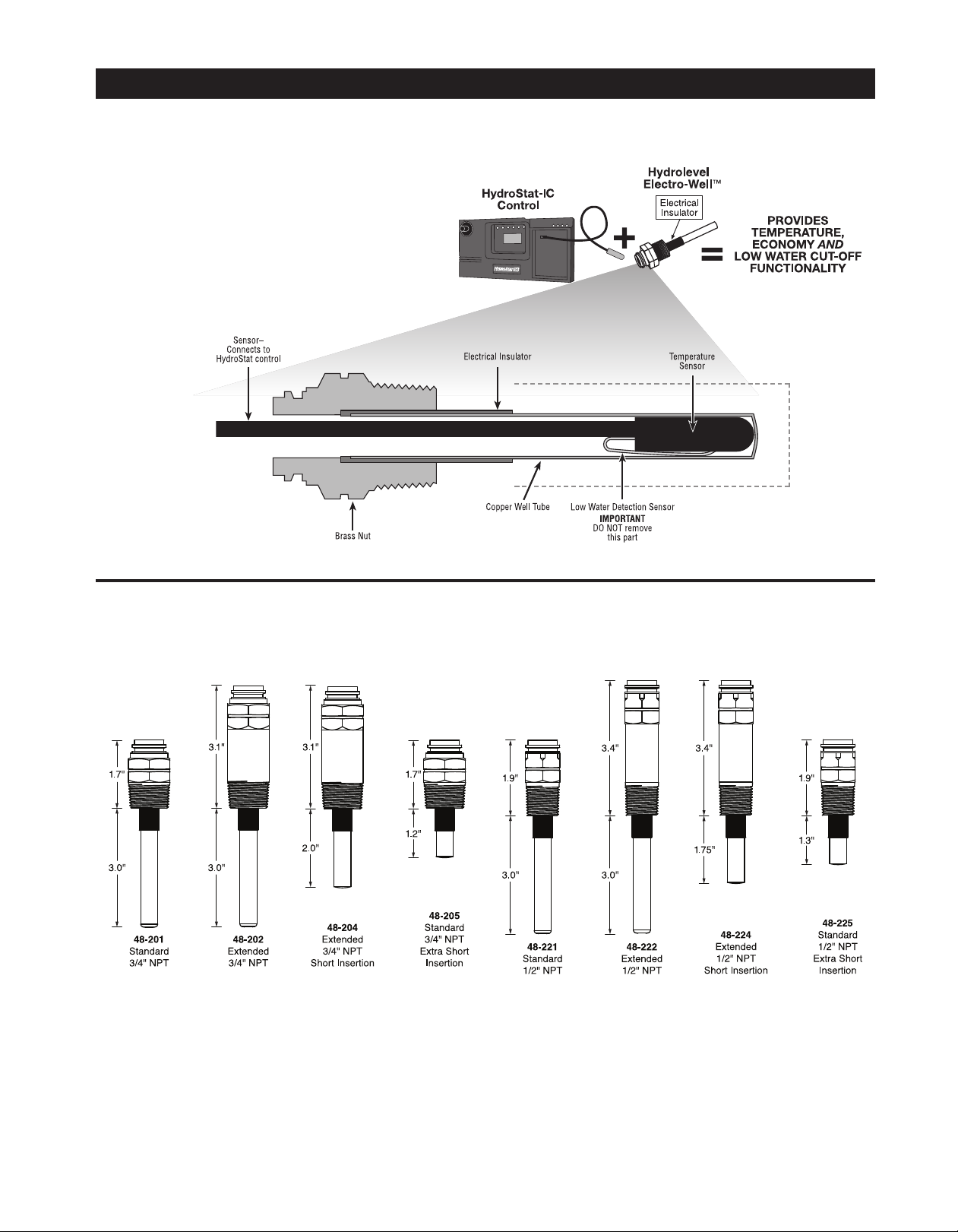
ELECTRO-WELLS
HydroStat-IC installed with
Electro-Well™
When installed with the Hydrolevel Electro-Well,
HydroStat-IC will provide both temperature and low
water cut-off functionality. If the control was supplied
by the boiler manufacturer, it was installed with an
Electro-Well. The Electro-Well is available separately
for field installations.
1/2" CLEARANCE
1/2" CLEARANCE
IMPORTANT:
For proper operation of the low
water cut-off function, there must be
a minimum of ½"
clearance between
the copper well
1/2" CLEARANCE
tube and any surface within the
boiler.
Electro-Well™ Models
15
Page 16
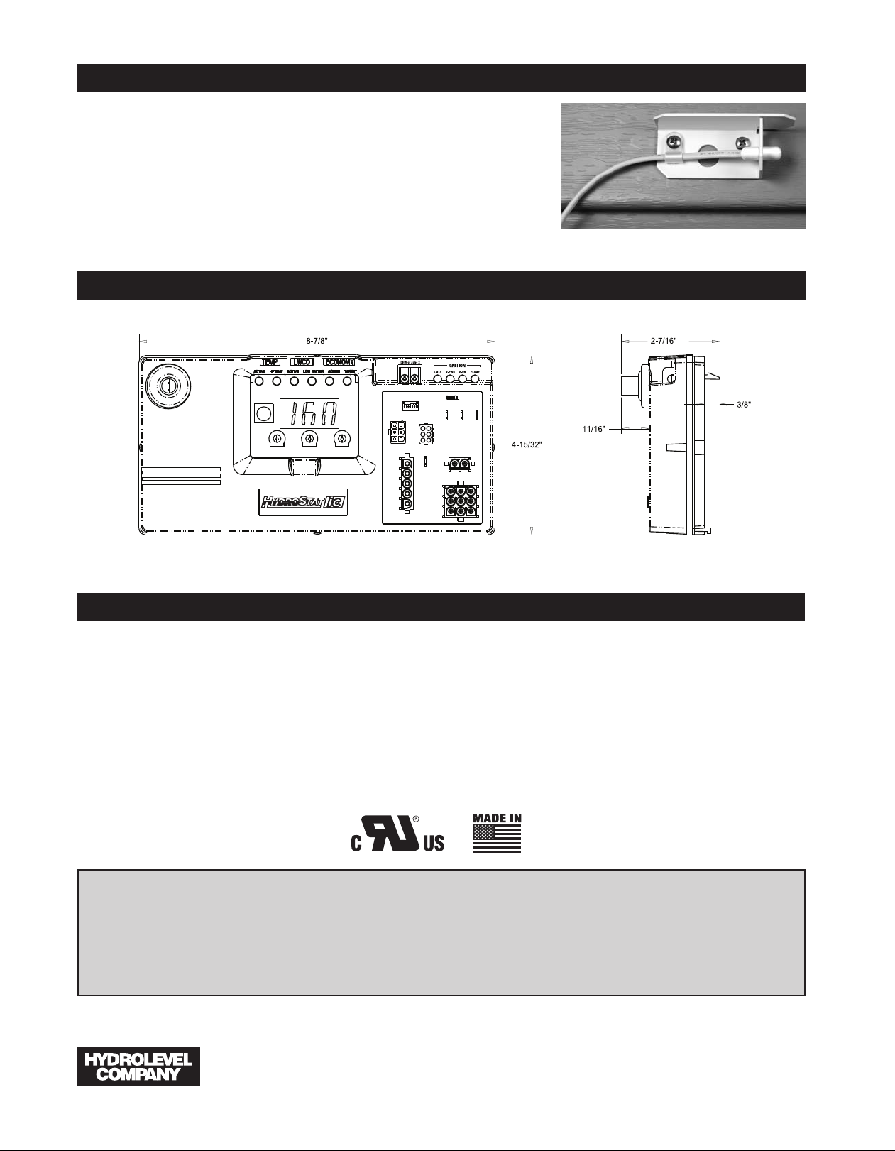
OUTDOOR SENSOR KIT
Hydrolevel's optional Outdoor Sensor Kit automatically activates outdoor reset
functionality and warm weather shutdown capability when plugged into the
HydroStat-IC control. This low cost, easy to install kit is available separately at
Hydrolevel distributors.
Part No. Description
48-140 Model OS-100 Outdoor Sensor Kit
48-145 Model OS-200 Wireless Outdoor Sensor Kit
DIMENSIONS
SPECIFICATIONS
HYDROSTAT-IC 4200 SERIES
Line voltage input: 120 VAC, 50/60 HZ
Low voltage input: 24 VAC, 40 VA
Inducer (4200i): 6 FLA, 18 LRA @ 120 VAC
Vent damper (4200a): 0.5 A @ 24 VAC
Circulator contacts: 5.8 FLA, 34.8 LRA @ 120 VAC
Operating range - low limit: Off or 110°F (43°C) - 200°F (93°C)
Operating range - high limit: 100°F (38°C) - 190°F (88°C)
Pilot valve: 2 A @ 24 VAC
LIMITED MANUFACTURER’S WARRANTY
We warrant products manufactured by Hydrolevel Company to be free from defects in
material and workmanship for a period of two years from the date of manufacture or
one year from the date of installation, whichever occurs first. In the event of any claim
under this warranty or otherwise with respect to our products which is made within
such period, we will, at our option, repair or replace such products or refund the purchase price paid to us by you for such products. In no event shall Hydrolevel Company
Main valve: 2 A @ 24 VAC
Operating ambient temp: -4°F (-20°C) to 150°F (66°C)
Thermostat anticipator: 0.2 A
Trial for ignition: 75 seconds (may vary by model)
Re-trial: 5 minutes
Flame current min: .8 µA
Flame currrent max: 7.3 µA
be liable for any other loss or damage, whether direct, indirect, incidental or consequential. This warranty is your EXCLUSIVE remedy and shall be IN PLACE OF any other
warranty or guarantee, express or implied, including, without limitation, any warranty
of MERCHANTABILITY or fitness for a particular purpose. This warranty may not be assigned or transferred and any unauthorized transfer or assignment thereof shall be void
and of no force or effect.
126 Bailey Road, North Haven, CT 06473 • Phone (203) 776-0473 • FAX (203) 764-1711 • www.hydrolevel.com
16
 Loading...