

PEERLESS WV-DV, WV-DV Series, WV-DV-03-075, WV-DV-03-085, WV-DV-03-110 Installation, Operation & Maintenance Manual
...Page 1
WV-DV
Boilers
Series
Oil
Installation,
Operation &
Maintenance
Manual
As an ENERGY STA R®Partner, PB Heat, LLC has determined that certain firing
rates of this product meet the
ENERGY STA R
®
guidelines for energy efficiency.
Page 2

Sidewall Venting
The Peerless WV-DV is designed and built to be vented through a side wall of a building using a
stainless steel concentric vent terminal (4 inch diameter tube inside an 8 inch diameter tube).
Exhaust gases from combustion contain water vapor. During the cooler months of the year, this
water vapor will condense into a visible vapor plume. This water vapor may condense on any
surface near the vent terminal. Care must be taken not to locate the vent terminal where the exhaust
gas, vapor plume and condensation could cause a hazard or a nuisance. Do not locate terminal
under a deck, for instance, as it may create a coating of ice on the deck during the winter months,
as well as shorten the life of the deck materials. Refer to Chapter 4 in this manual for specific
terminal location requirements. Condensate from a side wall vent terminal may also cause paint on
surrounding surfaces to crack and peel. If the boiler is used to heat potable (tap) water, the boiler
will cycle year round.The effects of hot exhaust gases and odors must be taken into consideration
during summer months.
Side wall vented, oil fired appliances may cause soot staining on wall surfaces surrounding their
terminals. To reduce the potential for staining, the boiler must be serviced annually. Soot and scale
must be completely removed from the combustion chamber and cast iron heat exchanger flueways.
See Chapter 7 in this manual. The oil burner must be completely serviced and set up according to
the specifications shown in Chapter 5 of this manual.
NOTICE
Page 3

1
USING THIS MANUAL 2
A. INSTALLATION SEQUENCE . . . . . . . . . . . . .2
B. SPECIAL ATTENTION BOXES . . . . . . . . . . . .2
1. PREINSTALLATION 3
A. ACCESSIBILITY CLEARANCES . . . . . . . . . . .3
B. CLEARANCES FROM COMBUSTIBLE
CONSTRUCTION . . . . . . . . . . . . . . . . . . . . . .3
2. BOILER SET-UP 4
A. SETTING UP THE BOILER . . . . . . . . . . . . . . .4
3. PIPING AND CONTROLS 5
A. BOILER SUPPLY AND RETURN . . . . . . . . . . .5
B. TANKLESS WATER HEATER . . . . . . . . . . . . .6
C. INDIRECT-FIRED WATER HEATER . . . . . . . .6
D. SAFETY RELIEF VALVE . . . . . . . . . . . . . . . . .6
E. CONTROLS . . . . . . . . . . . . . . . . . . . . . . . . . . .6
4. VENTING 7
A. VENT SYSTEM INSTALLATION . . . . . . . . . . .7
5. OIL BURNER 9
A. BURNER INSTALLATION . . . . . . . . . . . . . . . .9
6. ELECTRICAL 11
A. WIRING . . . . . . . . . . . . . . . . . . . . . . . . . . . . .11
B. ZONED SYSTEM WIRING . . . . . . . . . . . . . .11
7. MAINTENANCE 15
A. CLEANING HEATING SURFACES . . . . . . . .16
8. BOILER DIMENSIONS & RATINGS 17
9. REPAIR PARTS 18
TABLE OF CONTENTS
TABLE OF CONTENTS
Page 4
2
A. INSTALLATION SEQUENCE
Follow the installation instructions provided in this
manual in the order shown. The order of these
instructions has been set in order to provide the installer
with a logical sequence of steps that will minimize
potential interferences and maximize safety during
boiler installation.
B. SPECIAL ATTENTION BOXES
Throughout this manual you will see special attention
boxes intended to supplement the instructions and make
special notice of potential hazards. These categories
mean, in the judgment of PB Heat, LLC:
Indicates special attention is needed, but not directly
related to potential personal injury or property
damage.
NOTICE
Indicates a condition or hazard which will or can
cause minor personal injury or property damage.
CAUTION
DANGER
Indicates a condition or hazard which will cause
severe personal injury, death or major property
damage.
USING THIS MANUAL
USING THIS MANUAL
Indicates a condition or hazard which may cause
severe personal injury, death or major property
damage.
WARNING
Page 5
A. ACCESSIBILITY CLEARANCES
To provide for reasonable conditions of accessibility, the
following minimum clearances are recommended:
Alcove Installation.
1. 12" from left side
2. 24" from top
3. 24" from front
4. 9" from right side and rear
B. CLEARANCES FROM COMBUSTIBLE
CONSTRUCTION
The design of this boiler is certified for the following
clearances from combustible construction:
1. 0" from rear
2. 0" from right and left sides
3. 0" from top
4. 0" from vent pipe
5. 0" from vent connector
6. 0" from vent terminal
7. 24" from front
3
PREINSTALLATION
1. PREINSTALLATION
Read carefully, study these instructions before beginning work. It will save time. Study the included drawings. Save these
instructions for reference.
This boiler must be installed by a qualified contractor.
The boiler warranty can be voided if the boiler is not installed, maintained and serviced correctly.
The equipment shall be installed in accordance with those installation regulations in force in the local area
where the installation is to be made, including the current edition of NFPA-31. These shall be carefully followed
in all cases. Authorities having jurisdiction shall be consulted before installations are made.
NOTICE
Do not tamper with boiler or controls.
CAUTION
NEVER BURN GARBAGE OR PAPER IN THE UNIT,
AND NEVER LEAVE COMBUSTIBLE MATERIAL
AROUND IT.
CAUTION
Do not use this appliance if any part has been under
water. Improper or dangerous operation may result.
Immediately call a qualified service technician to
inspect the boiler and to replace any part of the
control system and any control which has been
under water.
WARNING
Page 6

4
BOILER SET-UP
A. SETTING THE BOILER
1. Prepare sketches and notes of the layout of the
installation. Include boiler location, venting system,
existing piping and wiring. Show existing equipment
that may interfere with installation of new
equipment. See Section 4-A. “Vent System
Installation,” Page 7, and Figure 4.1.
2. Provide a level foundation, located as close as
possible to the center of the heating system.
3. This boiler is suitable for use on combustible
flooring, provided the boiler is not set on carpet and
a metal drip pan is placed under the appliance.
4. See exploded view (Figure 9.1). After uncrating
boiler and setting it on foundation, open burner
mounting plate (Item 5) and make certain the target
wall (Item 2) is seated in the back of the combustion
chamber. (WV-DV-04) Ceramic fiber blanket base
liner (Item 3) should be lying flat on bottom of
combustion chamber between target wall and burner
mounting plate. Close burner mounting plate.
2. BOILER SET-UP
Page 7
5
A. BOILER SUPPLY AND RETURN
1. See Figure 3.1 for suggested piping to the boiler.
2. Make up cold water supply connection to the boiler.
3. Plug all open tappings in the boiler and fill with
water. Apply approximately thirty (30) psi pressure.
Check to make certain that all joints and fittings are
water tight.
4. After all joints and connections have been proven
water tight, remove cold water supply and plugs
from all tappings that are to be used. See Figure 8.1
for tapping locations.
5. Return water piping must be done in such a manner
to allow clearance from the burner mounting plate to
other piping when opening and closing the burner
mounting plate.
3. PIPING AND CONTROLS
PIPING AND CONTROLS
6. The supply and return connections should be sized to
suit the system. A 1-1/2" to 1-1/4" reducing coupling
may be used on the return where the system piping is
1-1/2". The supply should be out of the top of the
back section and return to the bottom of the front
section. There is a 3/4" tapping in the top of the back
section for air elimination.
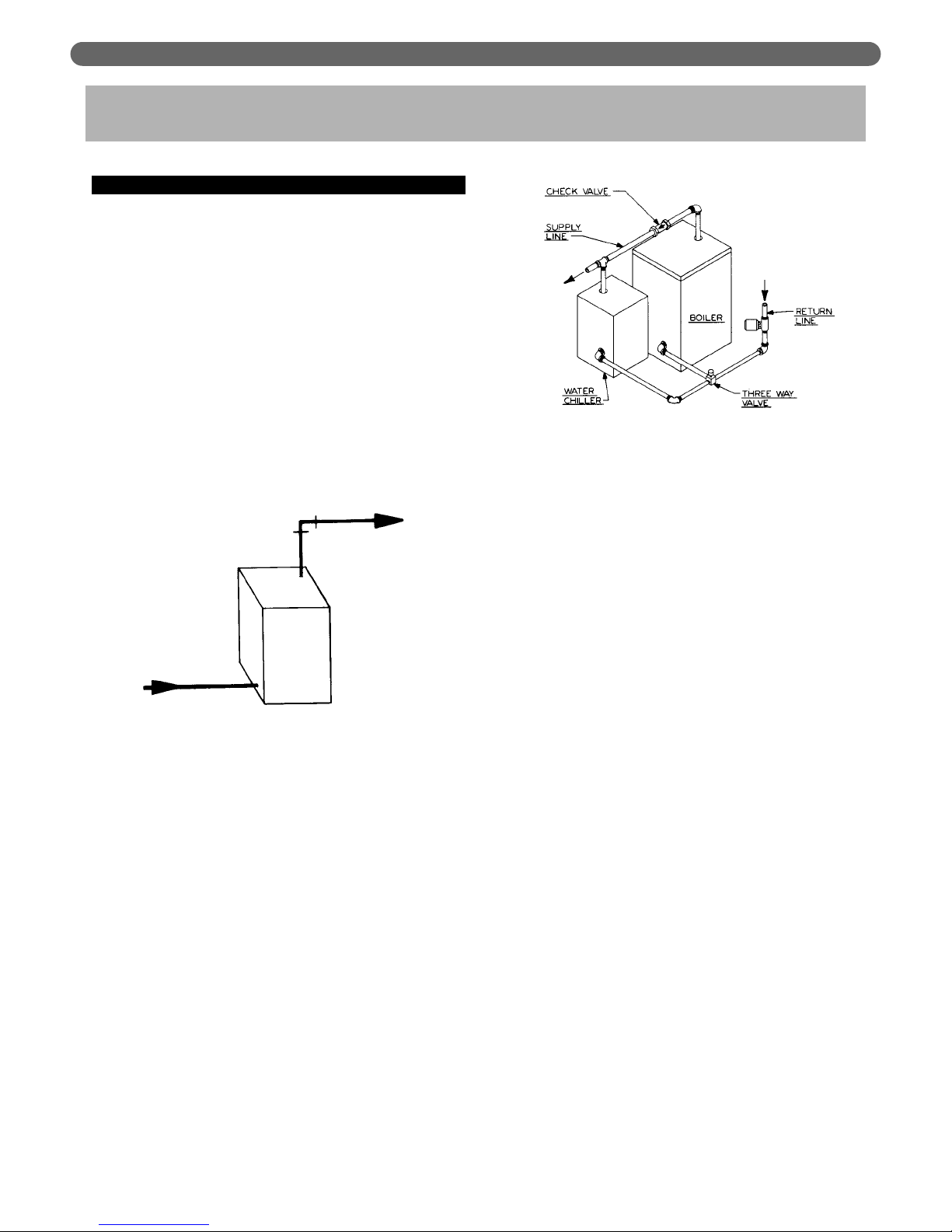
Figure 3.2
Note: If boiler is to be used in conjunction with a refrigeration
system, the chilled medium shall be piped in parallel with
boiler and proper valves applied to prevent the chilled
medium from entering the boiler. Refer to Figure 3.2.
When the boiler is connected to heating coils located in
air handling units, the boiler piping system must be
equipped with flow control valves or other automatic
devices to prevent gravity circulation of the boiler water
during the cooling cycle.
Figure 3.1
Page 8

6
B. TANKLESS WATER HEATER
C. INDIRECT-FIRED WATER HEATER
1. If a water boiler is to be used in conjunction with an
indirect-fired water heater refer to Figure 3.4 for
typical piping. Also refer to additional instructions
supplied with tank.
D. SAFETY RELIEF VALVE
1. Remove safety relief valve and 3/4" x 3" nipple from
parts bag. Install nipple and safety relief valve in top
or rear tapping. See Figure 8.1. If rear tapping is
used, installer must supply an elbow so that safety
relief valve is installed in vertical position.
E. CONTROLS
1. For complete information on servicing and
adjustment of controls, refer to the attached control
specification sheets.
Figure 3.3
Figure 3.4
Install mixing valve in hot water supply piping. Water
temperature above 125°F can cause severe burns
instantly or death from scalds.
DANGER
PIPING AND CONTROLS
Pipe the discharge of the safety relief valve to
prevent injury in the event of pressure relief. Pipe the
discharge to a drain. Provide piping that is the same
size as the relief valve.
CAUTION
Note: X-1019R, X-1020R and PP-1011R Coils installed in
WV-DV boilers have internal flow controls installed.
Do not use external flow controls with
these coils.
Page 9

A. VENT SYSTEM INSTALLATION
1. Determine vent terminal location:
a. Vent length must be between 3' and 20' long.
See paragraph 3 and Figure 4.1 for air intake
requirements.
b. No clearance is required between vent terminal
and combustible construction.
c. Vent terminal extends 12" beyond outside wall
surface and at least 16" beyond inside wall
surface. See Figure 4.1.
d. Provide 3' clearance above any forced air inlet
within 10'.
e. Provide 4' clearance below, 4' beside, or 1' above
any door, window, or gravity air inlet into any
building.
f. On multiple boiler installations, provide 18"
clearance between vent terminals. Located
terminals on same horizontal plane.
g. Provide 1' clearance between bottom of vent
terminal and ground level or between bottom of
vent terminal and normal snow lines.
h. Provide 4' horizontal clearance from, and in no
case above or below, unless a 4' horizontal
clearance is maintained, from electric meters, gas
meters, gas regulators, and gas relief equipment.
i. Provide 5' clearance to the vent outlet of a fuel
oil supply tank.
j. Provide 1' clearance to the soffit of the roof and
3' clearance to an inside corner of an L-shaped
building.
k. Do not locate vent terminal over public walkways
where condensate could create a nuisance or
hazard.
l. When adjacent to a public walkway, locate vent
terminal at least 7' above grade.
7
4. VENTING
VENTING
Figure 4.1: Venting
This boiler is shipped with a Flex-L International Vent
Terminal carton, and a Flex-L International Venting
Components Kit. The following components from
these two cartons must be used in the installation of
this boiler:
·
CeraFlex Oil Vent Terminal
·
CeraFlex Vent Pipe
·
CeraFlex Appliance Adapter
·
CeraFlex Terminal Adapter
· CeraFlex Sealant
NOTICE
This Oil-Fired Unit Shall be Connected to a Direct Vent
System, to Assure Safe Proper Operation of the Unit.
CAUTION
Table 4.1
Page 10

8
2. Use Flex-L International Inc. 4" diameter CeraFlex
Vent Pipe.
3. For air intake, use 4" diameter galvanized smoke
pipe or 4" diameter flexible corrugated aluminum
pipe. Maximum equivalent length of galvanized
smoke pipe is 40'. Allow 5 equivalent feet for each
90° elbow used. (Example: No more than 20' straight
smoke pipe can be used with four 90° elbows.) To
connect air intake to Riello BF5 burner, use burner
air adapter from trim bag to connect 4" air intake to
3" opening on top of burner. See Figure 4.1.
4. For specific installation and maintenance instructions
for the Flex-L Vent Terminal, Appliance Adapter,
Terminal Adapter, Burner Air Adapter (Riello only),
and Sealant that are included with the boiler, as well
as instructions for installation of flexible vent pipe and
air intake pipe, refer to Flex-L Manual #Y4-CF12
included in vent kit.
PB Heat, LLC requires that the vent slopes down 1/4"
per foot towards the vent terminal.This takes
precedence over the requirements shown in the
Flex-L manual.
NOTICE
VENTING
Page 11

9
A. BURNER INSTALLATION
1 The oil burner is supplied with a mounting flange
fixed in position.
2. BE SURE HI TEMP GASKET IS BETWEEN THE
BURNER MOUNTING FLANGE AND THE
COMBUSTION CHAMBER COVER PLATE.
3. Care must be taken when routing the oil lines so not
to interfere with the opening and closing of the
burner mounting plate. Flexible oil lines or flared
copper disconnects with valves (when copper lines
are used) may be installed to assure full opening of
the burner mounting plate when servicing.
Note: Two-pipe oil supply for Riello burner requires a sep-
arate kit. Order part #C7001026 from Riello dealer.
4. Oil Burner Specifications:
For information pertinent to the oil burner such as
nozzle sizing, fuel supply piping, adjusting or
servicing, refer to the charts below and the burner
installation manual.
5. Sampling tapping in CeraFlex Appliance Adapter must
be used for CO², smoke and flue pressure readings.
6. Burner should start automatically when thermostat is
turned up and main boiler service switch is turned
on. If burner does not start, check to be sure there is
oil in the tank and push reset button on burner
control: (Beckett) square red button; (Carlin) round
red button; (Riello) round red button inside clear
flexible cover on back of burner cover. If burner still
does not start, contact serviceman.
7. Burner and boiler can be shut down by turning
down the thermostat and moving the main boiler
service switch to the “off” position.
8. Post-purge timing on Riello BF5 burner is controlled
by 3/8" diameter dial near top right corner of
AL1009 circuit board inside burner cover. Post-purge
duration must be a minimum of one minute. Adjust
dial so arrow is pointing directly to the right (toward
mounting screw for AL1009 bracket). Check postpurge timing to confirm it is at least one minute long.
5. OIL BURNER
OIL BURNER
BURN ONLY #2 FUEL OIL IN THIS APPLIANCE. DO
NOT USE GASOLINE, CRANKCASE DRAININGS OR
ANY OIL CONTAINING GASOLINE.
CAUTION
Do not attempt to start the burner when excess oil
has accumulated, when the unit is full of vapor, or
when the combustion chamber is very hot.
CAUTION
Always keep the manual fuel supply valve shut off
if the burner is shut down for an extended period
of time.
CAUTION
Page 12

10
Table 5.1
Beckett NX Burner Specifications
Boiler Model No. Burner Model Nozzle Manufacturer, Size Pump Pressure (psig) Head/Air Setting Low Fire Baffle
WV-DV-03-075 NX70LB Delavan 0.60 60° W¹ 175 2.25 Ye s
WV-DV-03-085 NX70LB Delavan 0.65 60° W 175 3.00 Ye s
WV-DV-03-110 NX70LB Hago 0.85 60° B¹ 175 3.75 No
WV-DV-04-115 NX70HB Hago 0.85 60° B 170 1.50 Ye s
WV-DV-04-130 NX70HB Hago 1.00 60° B¹ 170 1.50 No
Table 5.2
Table 5.3
Carlin EZ1-HP Burner Specifications
Boiler Model No. Delavan Nozzle Size Pump Pressure (psig) Air Boot Setting Head Bar
WV-DV-03-075 .60 70° A¹ 150 0.5 0.75
WV-DV-03-085 .65 70° A¹ 150 0.6 0.75
WV-DV-03-110 .85 70° A 150 0.85 1.10 - 1.25
WV-DV-04-115 Hago 1.00 60° B¹ 140 1.00 1.10 - 1.25
WV-DV-04-130 Hago 1.10 60° B 140 1.25 1.10 - 1.25
Riello BF5 Burner Specifications
Boiler Model No. Nozzle Size Pump Pressure (psig) Turbulator Setting Air Damper Setting
WV-DV-03-075 Delavan .60 80° B¹ 165 1 3.3
WV-DV-03-085 Delavan .65 80° B¹ 165 1 3.8
WV-DV-03-110 Delavan .90 80° B 165 2 5.0
WV-DV-04-115 Hago .85 60° B¹ 180 2 5.0
WV-DV-04-130 Hago 1.10 60° B 140 4 5.0
Start-up and adjustment recommendations: Above Turbulator, Pin, Air Damper, and Air Dial settings are start-up settings only. Adjust burner for highest
CO²(no more than 13%) while maintaining a 0 smoke spot. Pressure or draft over fire and in flue cannot be adjusted. However, draft and/or pressure
measurements must be taken in these two locations and recorded for reference. All adjustments and measurements must be made using suitable
instruments such as those found in a Bacharach Combustion Test Kit.
Factory Installed Nozzles are indicated in Boldface.
1. Shipped Loose
OIL BURNER
Page 13

11
ELECTRICAL
A. WIRING
1. All electrical wiring shall be done in accordance with
the National Electrical Code and Local
Requirements. Single Pole Switches including those
of Safety Controls or Protective Devices shall not be
wired in a grounded line.
B. ZONED SYSTEM WIRING
1. Wire zone circulators as shown in Figures 6.4 and
6.5. Wire zone valves as shown in Figure 6.6.
6. ELECTRICAL
Do not connect power supply to Aquastat. To assure
service switch interrupts power to all boiler controls,
power supply must be connected to junction box as
shown below.
CAUTION
Figure 6.2: Beckett/Carlin Burner
Figure 6.1: Connecting Incoming Power
Page 14

12
ELECTRICAL
Figure 6.3: Riello Burner
Figure 6.4: Zoning With Circulators, Honeywell L8148 Aquastat
Page 15

13
ELECTRICAL
Figure 6.5: Zoning With Circulators, Honeywell L8124A, C Aquastat
Figure 6.6: Zoning With Zone Valves
Page 16

14
Figure 6.7: Partner with Circulator (Non-priority)
ELECTRICAL
Page 17

15
MAINTENANCE
7. MAINTENANCE
WARNING
Product Safety Information
Refractory Ceramic Fiber Product
This appliance contains materials made from refractory ceramic fibers (RCF). Airborne RCF
fibers, when inhaled, have been classified by the International Agency for Research on
Cancer (IARC), as a possible carcinogen to humans. After the RCF materials have been
exposed to temperatures above 1800°F, they can change into crystalline silica, which has
been classified by the IARC as carcinogenic to humans. If particles become airborne during
service or repair, inhalation of these particles may be hazardous to your health.
Avoid Breathing Fiber Particulates and Dust
Suppliers of RCF recommend the following precautions be taken when handling these materials:
Precautionar
y Measures:
Provide adequate ventilation.
Wear a NIOSH/MSHA approved respirator.
Wear long sleeved, loose fitting clothing and gloves to prevent skin contact.
Wear eye goggles.
Minimize airborne dust prior to handling and removal by water misting the material and
avoiding unnecessary disturbance of materials.
Wash work clothes separately from others. Rinse washer thoroughly after use.
Discard RCF materials by sealing in an airtight plastic bag.
Fir
st Aid Procedures:
Inhalation: If breathing difficulty or irritation occurs, move to a location with fresh clean air.
Seek immediate medical attention if symptoms persist.
Skin Contact: Wash affected area gently with a mild soap and warm water. Seek immediate
medical attention if irritation persists.
Eye Contact: Flush eyes with water for 15 minutes while holding eyelids apart. Do not rub
eyes. Seek immediate medical attention if irritation persists.
Ingestion: Drink 1 to 2 glasses of water. Do not induce vomiting. Seek immediate medical
attention.
Page 18

16
MAINTENANCE
A. CLEANING HEATING SURFACES
TO CLEAN:
1. Turn off all electrical power to the boiler before
beginning cleaning operation.
2. Remove top jacket panel and flue collector cover
plate, Item 11.
3. Brush the flue passages thoroughly from the top with
a wire brush. If unit is extremely dirty, brushing up
from the combustion chamber area also may be
necessary. The target wall is made of a soft ceramic
fiber. Care must be taken not to damage this
material during cleaning.
4. Remove any scale or soot from the combustion
chamber area by vacuum cleaning or any other
available means.
5. Replace oil burner and flue collector cover plate
making sure all gaskets are in place.
6. Replace jacket top panel.
7. Inspect venting system.
Entire heating system, including boiler, burner and
venting system, must be inspected at least once a
year by a qualified heating professional. Boiler is to
be cleaned at least once a year. To thoroughly clean
the boiler it must be brushed down from the top.
Alternately, for limited space or minimum clearance
to combustible installations, cleaning the heat
exchanger from the combustion chamber side is
acceptable.
NOTICE
Combustion chamber cover plate must be opened
to facilitate this operation.
NOTICE
Combustion chamber and flue collector may be
under pressure when burner is running. Flue
collector cover plate and combustion chamber
must be completely sealed before boiler is returned
to operation.
CAUTION
All Cover Plates, Enclosures, and Guards must be
maintained in place at all times, except during
maintenance and servicing.
NOTICE
Page 19

17
BOILER DIMENSIONS & RATINGS
8. BOILER DIMENSIONS & RATINGS
Table 8.1: WV-DV Ratings
1. Boiler Model No. may have the following suffix letters:
a. W–Water, b. P–Packaged, c. C–Circulator, d. T–Tankless Coil
2. Heating Capacity ratings are based on U.S. Government standard tests, with
13.0% CO².
3. The water ratings are based on piping pick-up allowance of 1.15. Consult factory
before selecting a boiler for gravity hot water installations and installations
having unusual piping and pick-up requirements, such as intermittent system
operation, extensive piping systems, etc.
4. Firing rate is based on a fuel oil with a heating value of 140,000 BTU per gallon.
Burner input based on maximum altitude of 2,000 ft. – for other altitudes
consult factory.
(1)
Boiler
Model
Number
(2)
Heating
Capacity
BTU/Hr.
(3)
Net I=B=R Ratings
BTU/Hr.
Water
(4)
I=B=R
Firing
Rate G.P.H.
WV-DV-03-075 92,000 80,000 0.75
WV-DV-03-085 103,000 90,000 0.85
WV-DV-03-110 131,000 114,000 1.10
WV-DV-04-115 141,000 122,000 1.15
WV-DV-04-130 158,000 137,000 1.30
Model A B
WV-DV-03
14¹⁄₈" 7¹⁄₁₆"
WV-DV-04
18¹⁄₈" 9¹⁄₁₆"
Figure 8.1: WV-DV Boiler Views
Page 20

18
REPAIR PARTS
9. REPAIR PARTS
Figure 9.1: Repair Parts
Repair parts are available from your installer or by contacting PB Heat, LLC, P.O. Box
447, New Berlinville, PA 19545-0447.
Note: Remember to include boiler model number and serial number when ordering parts.
5a
5b
5c
5d
5e
Page 21

19
Table 9.1: Repair Parts**
**See Figure 9.1
REPAIR PARTS
Item
No.
Description
Additional
Information
Stock Code
WV-DV-03
Stock Code
WV-DV-04
1
Block Assembly Water WPCT
— 90183 90184
Block Assembly Water WPC
— 90186 90187
2
Target Wall
— 50795 50795
3
Base Liner
— — 50857
4
Swing Door Hinge
— 3903 3903
5
Burner Mounting Plate Assembly
— PP1051 PP1051
Burner Mounting Plate Insulation
— 50794 50794
Flame Observation Assembly
— 90754 90754
5a
Flame Observation Cover Plate
— SC1007P SC1007P
5b
Face Gasket
— 50230 50230
5c
Pyrex Observation Window
— 51681 51681
5d
Ring Gasket
— 50229 50229
5e
Observation Glass Holder
— X1138P X1138P
6
Burner Mounting Plate Rope Seal — 51210 51210
7
Steel Cover Plate (Front) Water — 99812 99812
8
Rubber Gasket (Front Plate) — 51800
51800
9
Tankless Coil — 90637
90534
10
Flue Collector Plate Blanket Seal — 90999
90999
11
Flue Collector Cover Plate — 50245
50253
12
Rope Seal — 51209
51209
13
Rear Outlet Cover Plate — 90563
90563
15
Jacket Assembly — 90098
90418
Oil Burner
Specify Brand Name
and Boiler Size
—
—
Temperature-Pressure Gauge
— — —
Aquastat
— — —
Drain Valve
— — —
Relief Valve
— — —
Boiler Vent Adapter
CFAA44P 7612 7612
Flexible Pipe Termination Adapter
CFAT44 7613 7613
Riello Burner Adapter
CFBA34-RL 7615 7615
Tube of Sealant
XMMSC5 7616 7616
Concentric Vent Termination Kit
CFT4 91776 91776
Page 22

20
NOTES
Page 23

21
NOTES
Page 24

HI Division
of gama
ASME
PP8076 R5 (2/06-3M)
Printed in U.S.A.
©2006
WV-DV
Boilers
Series
Oil
Installation,
Operation &
Maintenance
Manual
TO THE INSTALLER:
This manual is the property of the owner and must
be affixed near the boiler for future reference.
TO THE OWNER:
This boiler should be inspected annually by a
Qualified Service Agency.
Service Information
PB HEAT, LLC
P.O. BOX 447 • NEW BERLINVILLE, PA 19545-0447
Name:
Address:
Phone:
 Loading...