

Page 1
Assembly Instructions - External Wall Plate
MAXIMUM LOAD
*
CAPACITY:
150 lb (68 kg)
Models: WSP 420, WSP 420S, WSP 420W,
WSP 425, WSP 425S, WSP 425W,
WSP 430, WSP 430S, WSP 430W,
WSP 435, WSP 435S, WSP 435W,
WSP 440, WSP 440S, WSP 440W,
WSP 445, WSP 445S, WSP 445W
IMPORTANT! Read entire instruction sheet before you
start installation and assembly.
WARNING
• Wall or mounting structure must be capable of supporting a minimum static load of 600 lb (272 kg).
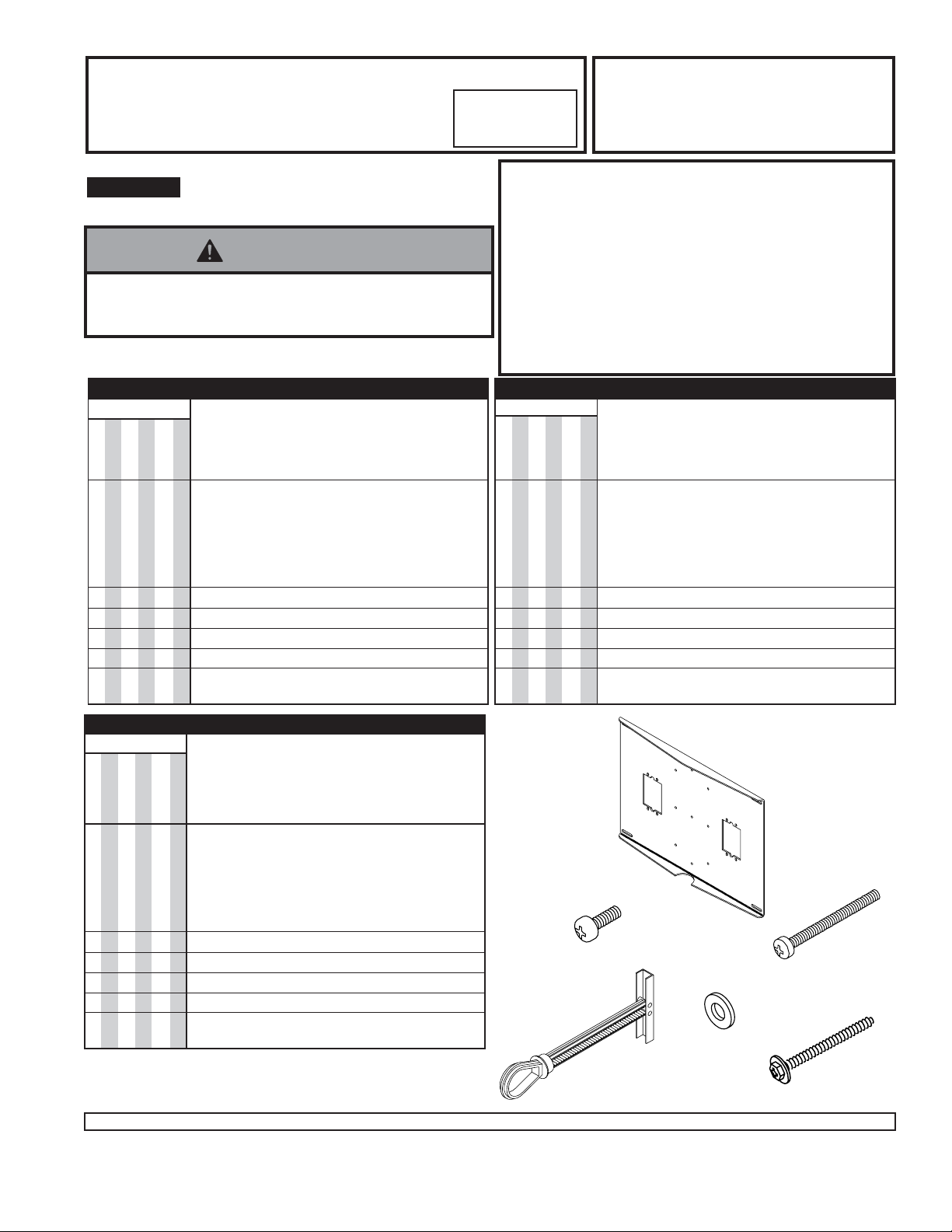
PARTS LIST
MODEL #
WSP 420
WSP 425
WSP 430
WSP 435
WSP 440
WSP 445
PART # QTY. DESCRIPTION
9
9
9
9
9
9
9
9
9
9
9
9
9
9
9
9
9
9
9
9
9
9
9
9
A 024-1032 1 wall plate (black)
024-1033
024-1034
024-1035
9
9
9
9
9
9
024-1036
024-1037
9
B 510-9108 4 1/4-20 x 1/2" phillips screw
9
C 520-9521 4 1/4-20 x 2 1/2" phillips screw
9
D 560-9708 4 toggler
9
E 540-9440 8 washer
9
F 5S1-015-C03 4 #14 x 2.5" (6 mm x 65 mm)
9
washer head wood screw
WSP 420, WSP 420S, and WSP 420W for studs on 16" (406 mm)
centers.
WSP 425, WSP 425S, and WSP 425W for studs on 16" (406 mm)
centers, contains two electrical box knockouts.
WSP 430, WSP 430S, and WSP 430W for studs on 20" (508 mm)
or 16" (406 mm) centers.
WSP 435, WSP 435S, and WSP 435W for studs on 20" (508 mm)
or 16" (406 mm) centers, contains two electrical box knockouts.
WSP 440, WSP 440S, and WSP 440W for studs on 24" (610 mm),
20" (508 mm) or 16" (406 mm) centers.
WSP 445, WSP 445S, and WSP 445W for studs on 24" (610 mm),
20" (508 mm) or 16" (406 mm) centers, contains two electrical box
knockouts.
PARTS LIST
MODEL #
WSP 420S
WSP 425S
9
9
9
9
9
9
9
9
9
9
9
9
9
9
9
9
9
9
WSP 430S
WSP 435S
9
9
9
9
9
9
9
9
9
9
9
9
PART # QTY. DESCRIPTION
WSP 440S
WSP 445S
A 024-4032 1 wall plate (silver)
024-4033
024-4034
024-4035
024-4036
024-4037
9
B 520-9511 4 1/4-20 x 1/2" phillips screw
9
C 520-9522 4 1/4-20 x 2 1/2" phillips screw
9
D 560-9708 4 toggler
9
E 540-9444 8 washer
9
F 5S1-015-C04 4 #14 x 2.5" (6 mm x 65 mm)
9
washer head wood screw
PARTS LIST
MODEL #
WSP 420W
WSP 425W
WSP 430W
WSP 435W
9
9
9
9
9
9
9
9
9
9
*
Visit the Peerless Web Site at www.peerlessindustries.com For customer service call 1-800-729-0307 or 708-865-8870.
9
9
9
9
9
9
9
Refers to maximum weight of TV or max.
combined weight of TV, VCR and VCR Bracket.
9
9
9
9
9
9
9
9
9
9
9
9
9
PART # QTY. DESCRIPTION
WSP 440W
WSP 445W
A 024-2032 1 wall plate (white)
024-2033
024-2034
024-2035
024-2036
024-2037
9
B 520-9511 4 1/4-20 x 1/2" phillips screw
9
C 520-9522 4 1/4-20 x 2 1/2" phillips screw
9
D 560-9708 4 toggler
9
E 540-9444 8 washer
9
F 5S1-015-C04 4 #14 x 2.5" (6 mm x 65 mm)
9
washer head wood screw
1 of 4
B
D
ISSUED: 12-06-95 SHEET #: 024-9001-3 11-30-06
A
C
E
F
Page 2
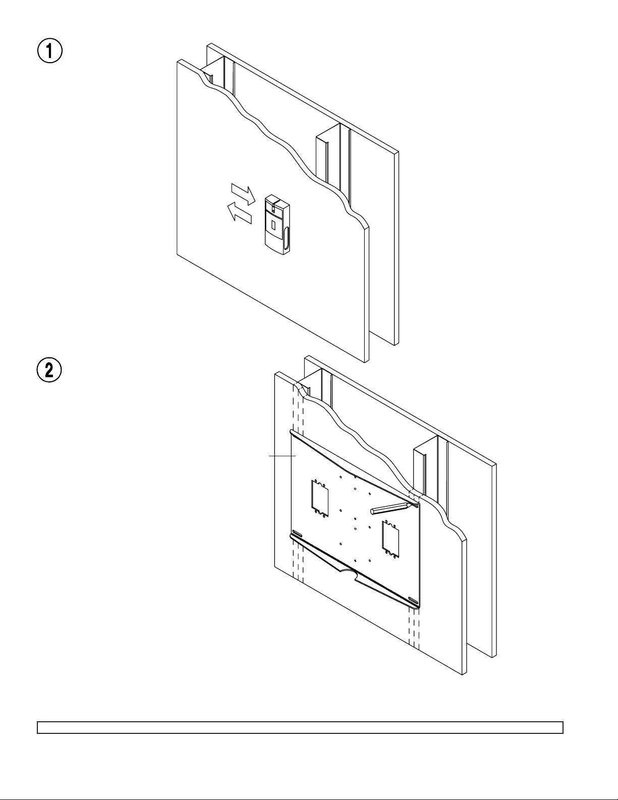
Use a stud
finder to locate stud
centers.
Use wall plate
(A) as a template to
mark slot centers on
stud centers.
Note: Models WSP 430, WSP 430S, WSP
430W, WSP 435, WSP 435S, and WSP
435W can be mounted on both 20" or 16"
centers. Models WSP 440, WSP 440S,
WSP 440W, WSP 445, WSP 445S, and WSP
445W can be mounted on 24", 20", or 16"
centers.
A
2 of 4
Visit the Peerless Web Site at www.peerlessindustries.com For customer service call 1-800-729-0307 or 708-865-8870.
ISSUED: 12-06-95 SHEET #: 024-9001-3 11-30-06
Page 3

Steps 3 and 4 cover attachment to a metal stud wall. For attachment to a wood stud wall skip to step 5, page 4.
FOR MET AL STUD W ALLS ONL Y : Drill four
1/2" (13 mm) dia. holes through drywall and
studs. Insert togglers (D) as shown below...
• Make sure that mounting screws are anchored into the
center of the studs. The use of an "edge to edge" stud
finder is highly recommended.
WARNING
D
∅ 1/2"
(13 mm)
Pivot end of
toggler.
Push into
hole.
Rotate toggler
clockwise to
wedge it
against inside
walls of metal
stud.
Slide plastic
cap forward
while pulling
back firmly on
ring.
D
Break off
excess.
3 of 4
Visit the Peerless Web Site at www.peerlessindustries.com For customer service call 1-800-729-0307 or 708-865-8870.
ISSUED: 12-06-95 SHEET #: 024-9001-3 11-30-06
Page 4

Attach wall plate (A) with 1/4-20 x 2.5" phillips
screws (C), and washers (E).
Four 1/4-20 x 1/2" phillips screws (B), and four
washers (E) are provided to attach wall mount bracket
(sold separately) to wall plate.
E
C
Step 5 covers attachment to a wood stud wall.
FOR WOOD STUD WALLS ONL Y drill four 5/32" (4 mm)
dia. holes 2 1/2" (65 mm) deep. Att ach wall plate (A)
using four #14 x 2.5"(6 mm x 65 mm) wood screws (F).
WARNING
• Tighten wood screws so that wall plate is firmly
attached, but do not overtighten. Overtightening can
damage the screws, greatly reducing their holding
power.
• Never tighten in excess of 80 in • lb (9 N.M.).
• Make sure that mounting screws are anchored into the
center of the studs. The use of an "edge to edge" stud
finder is highly recommended.
A
A
Four 1/4-20 x 1/2" phillips screws (B), and four washers
(E) are provided to attach wall mount bracket (sold
separately) to wall plate.
F
4 of 4
Visit the Peerless Web Site at www.peerlessindustries.com For customer service call 1-800-729-0307 or 708-865-8870.
© 2006 Peerless Industries, Inc. All rights reserved.
Peerless is a registered trademark of Peerless Industries, Inc.
All other brand and product names are trademarks or registered trademarks of their respective owners.
ISSUED: 12-06-95 SHEET #: 024-9001-3 11-30-06
 Loading...