

peerless-AV WL-AU-PST600A, WL-AU-AVWSA, WL-AU-PST1200A-W, WL-AU-PST1200A, WL-AU-PST1600A User Manual
...Page 1
ISSUED: 06-10-13 SHEET #: 180-9050-2 05-15-14
2300 White Oak Circle • Aurora, Il 60502 • (800) 865-2112 • Fax: (800) 359-6500 • www.peerless-av.com
User Manual
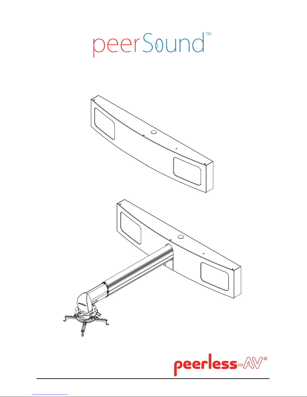
WL-AU-AVWSA(-W)
Wireless Audio Wall System
Wireless Short Throw Projector Audio System
WL-AU-PST600A(-W)
WL-AU-PST1200A(-W)
WL-AU-PST1600A(-W)
Page 2

2 of 12
Contents
Safety Instructions .......................................................................................................................... 3
Electrical Warnings ......................................................................................................................... 4
Introduction ...................................................................................................................................... 5
Amplifi er ........................................................................................................................................... 6
Troubleshooting ............................................................................................................... ............... 7
Product Specifi cations.................................................................................................................... 8
Warranty .........................................................................................................................................10
Contact Information ...................................................................................................................... 10
Page 3

3 of 12
Safety Instructions
Read these instructions as well as referenced instruction for each respective electronic component.
Keep these instructions as well as referenced instruction for each respective electronic component.
Heed all warnings in this instruction as well as referenced instruction for each respective electronic
component. Follow all instructions including referenced instruction for each respective electronic
component.
1. Do not use this or an included component of this system near water.
2. Clean only with dry cloth.
3. Do not block any ventilation openings. Install in accordance with the user manual instructions for
included electronic components.
4. Do not install near any heat sources such as radiators, heat registers, stoves, or other apparatus
that produce heat.
5. Do not defeat the safety purpose of the polarized or grounding-type plug. A polarized plug has
two blades with one wider than the other. A grounding type plug has two blades and a third
grounding prong. The wide blade or the third prong are provided for your safety. If the provided
plug does not fi t into your outlet, consult an electrician for replacement of the obsolete outlet.
6. Protect the power cord from being walked on or pinched particularly at plugs, convenience
receptacles, and the point where they exit from the system.
7. Unplug this system during lightning storms or when unused for long periods of time.
8. Refer all servicing to qualifi ed service personnel. Servicing is required when the system has
been damaged in any way such as power-supply cord or plug is damaged, liquid has been
spilled or objects have fallen into the system, the system has been exposed to rain or moisture,
does not operate normally, or has been dropped.
9. Never push objects of any kind into the system through openings as they may touch dangerous
voltage points or short-out parts that could result in a fi re or electric shock. The system shall not
be exposed to dripping or splashing and no objects fi lled with liquids, such as vases shall be
placed on the system. Do not put candles or other burning objects on top of this system.
10. If you install the system in a built-in installation, such as a bookcase or rack, ensure that there is
adequate ventilation.
11. Leave 1" (2.5cm) of free space at the top and sides and 1" (2.5cm) at the rear. The rear edge
of the shelf or board above the system shall be set 1" (2.5cm) away from the rear panel or wall,
creating a fl ue-like gap for warm air to escape.
WARNING
To reduce the risk of fi re or electric shock, do not expose this system to rain or moisture.
WARNING
To prevent injury, this system must be securely attached to the wall in accordance with the installation
instructions.
WARNING
Batteries (battery pack or batteries installed) shall not be exposed to excessive heat such as
sunshine, fi re or the like. Do not use batteries of they are noticeably damaged.
CAUTION
To reduce the risk of electric shock, do not perform and servicing other than that contained in the
operating instructions unless you are qualifi ed to do so.
Page 4

4 of 12
Electrical Warnings
A. Avoid Abuse to the Power Supply
To reduce risk of electric shock, unplug the power supply from outlet before attempting any
maintenance or cleaning. Turning off controls will not reduce this risk.
DO NOT disassemble the power supply.
Contact a qualifi ed service professional if service or repair is required. Incorrect reassembly
may result in a risk of electric shock or fi re.
DO NOT expose the power supply to rain, snow, water, gas, oil, etc.
DO NOT operate the power supply if it has been dropped, or otherwise damaged in any way.
DO NOT block or cover the apparatus and impeded ventilation.
B. Proper Use of The Power Supply and Wiring
It is recommended to always use the provided power supply. An extension cord should not be
used unless absolutely necessary. Use of improper extension cord could result in a risk of fi re
and/or electric shock. If extension cord must be used, use ONLY a grounded, 3-wire type cord.
NEVER use a 2-wire cord and an adaptor! The cord MUST be plugged into a grounded outlet.
Make sure the grounded outlet is properly wired, in good electrical condition, and wire size is
large enough for AC ampere rating of the power supply as specifi ed below. AWG = American
Wire Gauge.
To reduce risk of damage to plug and cord when disconnecting the power supply, ALWAYS pull
on plug - NEVER on cord. Locate cord so that it will not be stepped on, tripped over, or otherwise subject to damage or stress.
DO NOT lay extension cord on battery or the power supply.
DO NOT operate the power supply with damaged cord or plug - replace them immediately.
Follow Manufacturers' Recommendations
Before using the system , read all instructions and caution markings on the system and read the user
guide.
Page 5

5 of 12
Introduction
You have purchased the most multifunctional, easy to use Wireless Audio system. This system
provides audio mixing allowing for enhanced voice over AV when paired with a wireless microphone
(not included). Enhanced voice allows the speaker to be heard over the AV content all the way in the
back of the room, reducing voice strain and engaging the audience.
NOTE: It is recommended that this system be installed and set up by a professional installer that can
ensure that:
1. The correct projector arm length based on the projector requirements is selected
(WL-AU-PST600A(-W), 1200A(-W), 1600A(-W) models only)
2. That proper 120 VAC power is supplied to the system
3. That the audio functions are set up per system specifi cations
NOTE: Improper installation can result in either a poor or non-operating system.
Basic Guidelines
This manual is intended to cover operation of the amplifi er for audio reproduction. A wireless
microphone (not included) is supported by this system. It is the choice of the customer or the
professional installer to utilize the systems full audio capabilities. This manual will provide general
information on microphones, but specifi c details many vary based on microphone model selected and
must be found in the selected microphone's manual.
Batteries
The only batteries utilized are in the remote control for the amplifi er. The amplifi er remote will be used
frequently, thus needing more frequent replacement.
The main sign of needing replacement is reduced distance of operation.
The battery models are as follows:
Amplifi er Remote: CR2025
NOTE: Batteries are NOT rechargeable
Page 6

6 of 12
Amplifi er
1. POWER ON/OFF
ON -To initially turn the amplifi er on, depress the power button on the face. The LED will turn to
green. The amplifi er will respond to remote control commands.
Remote Control OFF/ON –Turn the power off by using the remote control. This is a sleep
mode. The main power button is still pressed in. Continued on/off cycles to be handled using
the remote control only. If the power is again turn off using the face button in sleep mode, the
amplifi er would turn back on in sleep mode.
OFF – Turning the amplifi er off pressing the button on the face, the amplifi er is completely off.
It will not respond to the remote control. It will also go back on in the mode it was previously in
(either sleep or on).
2. LED POWER INDICATOR
OFF – When the amplifi er is off, it will not respond to the remote control commands.
Red - Sleep mode. The amplifi er was turned off by the remote only, and will only turn on by the
remote control. The main power button is still pressed in.
Green – The amplifi er is on and will provide sound with signal from either Aux or Mic, and
responds to the remote control.
3. VOLUME ADJUSTMENT
The volume adjustment controls both the Aux input and Mic input the same. The signal from both
inputs ramps up or down the same amount. The volume adjustment is done by using the up or
down buttons on the amplifi er face, or using the up or down buttons on the remote control. The
LED will fl ash green during the button presses.
AMPLIFIER
SIGNAL MIXING
Your system is set up to allow a microphone (not included) to be heard slightly over the AV content
running. Contact your installer, or refer to the installation manual if further adjustment is needed.
1
3
2
Page 7

7 of 12
Audio
Sound does not come out of the speakers:
• Ensure the volume on the source (Computer/PC, Blu-Ray™ Disc Player, Gaming Console,
etc.) is turned up at least half way or more.
• Ensure the amplifi er indicator light is green, indicating it’s ON. If it is red, use the Audio
Remote to turn it ON. If the light is not on, check the amplifi er face power button is pressed in,
or press it in. If it still does not turn on, request help to remove the front cover, and ensure the
system has power.
• Check amplifi er volume level. Use the Amplifi er Remote to turn up the volume. The amplifi er
green indictor light will blink while the volume button is pressed. Full volume occurs when the
green light stops blinking, while pressing the UP button.
The microphone cannot be heard from the speakers:
• Ensure the microphone batteries are fresh.
• Ensure the microphone is turned on.
• Ensure variable gain adjustments are not turned down.
• Ensure the installer adjusted the microphone gain control on the amplifi er, accessed by
removing the system front cover.
• Ensure the microphone is still linked to it’s receiver, accessed by removing the system front
cover.
NOTE: Some items above may require checking your microphone user manual.
Troubleshooting
Page 8

8 of 12
Product Specifi cations
Wireless Short Throw Projector AV System
Part Number WL-AU-PST600A(-W)
WL-AU-PST1200A(-W)
WL-AU-PST1600A(-W)
Product Weight WL-AU-PST600A(-W) 43.00lb (19.50kg)
WL-AU-PST1200A(-W) 46.50lb (21.09kg)
WL-AU-PST1600A(-W) 48.00lb (21.77kg)
Dimensions (W x H x D) WL-AU-PST600A(-W) 47.21" x 11.06" x 19.44"-26.33"
(1199 x 281 x 494-669mm)
WL-AU-PST1200A(-W) 47.21" x 11.06" x 32.43"-49.95"
(1199 x 281 x 824-1269mm)
WL-AU-PST1600A(-W) 47.21" x 11.06" x 48.18"-65.71"
(1199 x 281 x 1224-1669mm)
Max Projector Load 25lb (11.3kg)
Universal Projector Mounting Pattern Up to 17.63" (448mm)
Pitch +15 °/-20° (PRGS-UNV) / ±20° (PRG-UNV)
Roll ±5° (PRGS-UNV) / ±10° (PRG-UNV)
Swivel 360° (during installation)
Color WL-AU-PST600A/-PST1200A/-PST1600A Black
WL-AU-PST600A-W/-PST1200A-W/-PST1600A-W White
Mounting Surfaces Wood stud, metal stud, concrete and other structures
(Other structures require accessory)
Product Specifications
Power rating
Inputs 3.5mm stereo Auxiliary jack, 3.5mm stereo microphone jack
Outputs Bridgeable stereo speaker jacks
Volume Control Wireless IR remote control
Onboard local volume control
Audio controls Base, treble, balance adjustments
Microphone input gain adjustment
Stereo / bridge mono switch
Power source Voltage: 120V AC, 60Hz; Consumption: 24V DC, 2A
Amplifier Specifications
Speaker 5-1/4" 2-way speakers with 35W maximum power handling
1" post tweeters
60Hz to 20kHz frequency response
86 dB sensitivity
Speaker Specifications
Page 9

9 of 12
Wireless AV Wall System
Power rating
Inputs 3.5mm stereo Auxiliary jack, 3.5mm stereo microphone jack
Outputs Bridgeable stereo speaker jacks
Volume Control Wireless IR remote control
Onboard local volume control
Audio controls Base, treble, balance adjustments
Microphone input gain adjustment
Stereo / bridge mono switch
Power source Voltage: 120V AC, 60Hz; Consumption: 24V DC, 2A
Amplifier Specifications
Speaker 5-1/4" 2-way speakers with 35W
maximum power handling 1" post tweeters
60Hz to 20kHz frequency response
86 dB sensitivity
Speaker Specifications
Part Number WL-AU-AVWSA
WL-AU-AVWSA-W
Product Weight 28.50lb (12.93kg)
Dimensions (W x H x D) 47.21" x 9.75" x 5.58"
(1199 x 248 x 142mm)
Color WL-AU-AVWSA - Black
WL-AU-AVWSA-W - White
Mounting Surfaces Wood stud, metal stud, concrete and other structures
(Other structures require accessory)
Product Specifications
Page 10

10 of 12
Warranty
Peerless Industries, Inc. (“Peerless-AV®”) warrants to original end-users of Peerless-AV® products that PeerlessAV® products will be free from defects in material and workmanship, under normal use, for the periods listed below,
from the date of purchase by the original end-user. At its option, Peerless-AV® will repair or replace with new or
refurbished products or parts, or refund the purchase price of any Peerless-A V® product which fails to conform with
this warranty.
In no event shall the duration of any implied warranty of merchantability or fi tness for a particular purpose
be longer than the period of the applicable express warranty set forth above. Some states do not allow
limitations on how long an implied warranty lasts, so the above limitation may not apply to you.
This warranty does not cover damage caused by (a) service or repairs by the customer or a person who is not
authorized for such service or repairs by Peerless-AV
®
, (b) the failure to utilize proper packing when returning the
product, (c) incorrect installation or the failure to follow Peerless-AV®’s instructions or warnings when installing,
using or storing the product, or (d) misuse or accident, in transit or otherwise, including in cases of third-party
actions and force majeure. This warranty also does not cover corrosion or rust resulting from damaged, scratched
or chipped paint or other surfaces.
In no event shall Peerless-AV
®
be liable for incidental or consequential damages or damages arising
from the theft of any product, whether or not secured by a security device which may be included with
the Peerless-AV® product. Some states do not allow the exclusion or limitation of incidental or consequential
damages, so the above limitation or exclusion may not apply to you.
This warranty is in lieu of all other warranties, express or implied, and is the sole remedy with respect to product
defects. No dealer, distributor, installer or other person is authorized to modify or extend this Limited Warranty or
impose any obligation on Peerless-AV
®
in connection with the sale of any Peerless-AV® product.
This warranty gives specifi c legal rights, and you may also have other rights which vary from state to state.
Product
Mounts
Furniture
Cables
Cleaning Products
Electronic Products and components
Warranty Period
5 years
1 year
25 years
1 year
1 year
Customer Care
Need help with installation or set up? Call Peerless-AV Customer Care
1-800-865-2112 (available 7:00am- 7:00pm CST, Monday - Friday), or email us at
info@peerless-av.com.
Peerless -AV
2300 White Oak Circle
Aurora, IL 60502 USA
peersound.peerless-av.com
Contact Information
Page 11

Notes:
Page 12

Peerless -AV
2300 White Oak Circle
Aurora, IL 60502 USA
peersound.peerless-av.com
©2013 Peerless-AV. All rights reserved. Peerless-AV is a trademark of Peerless Industries, Inc.
Other parties’ marks are the property of their respective owners.
 Loading...