

peerless-AV WL-AU-AVWS, WL-AU-AVWS-W, WL-AU-AVWSA, WL-AU-AVWSA-W Installation And Assembly Manual
Page 1
ISSUED: 2012-10-11 SHEET #: 180-9041-2 2012-05-31
2300 White Oak Circle • Aurora, Il 60502 • (800) 865-2112 • Fax: (800) 359-6500 • www.peerless-av.com
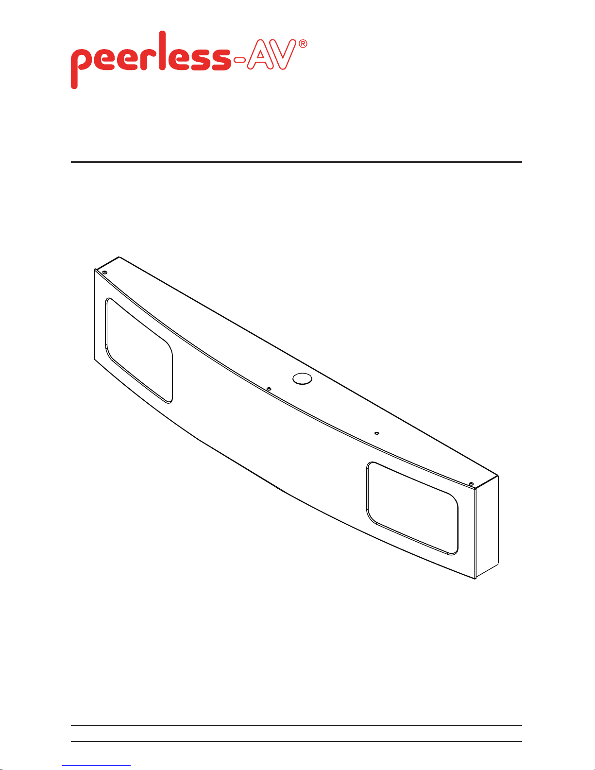
Installation and Assembly:
PeerSound™ Wireless AV Wall System
PeerSound™ Wireless Audio Wall System
Models: WL-AU-AVWS, WL-AU-AVWS-W, WL-AU-AVWSA, WL-AU-AVWSA-W
Page 2

Page 3

3
ISSUED: 2012-10-11 SHEET #: 180-9041-2 2012-05-31
NOTE: Read entire instruction sheet before you start installation and assembly.
Table of Contents
Parts List................................................................................................................................................4
Installation to Double Stud Wall .............................................................................................................6
Installation to Metal Stud Wall ............................................................................................................... 8
Installation to Solid Concrete or Cinder Block......................................................................................10
Component Connections......................................................................................................................17
Amplifi er................................................................................................................................................18
Amplifi er Setup......................................................................................................................................19
Wireless Microphone Setup...................................................................................................................19
Tools Needed for Assembly
• stud fi nder ("edge to edge" stud fi nder is recommended)
• phillips screwdriver
• drill
• 3/8" bit for solid concrete surface
• 3/16" bit for wood studs
• 1/2" bit for metal studs
• socket wrench
• 7/16" socket
• level
• hammer
• Pencil
• Tape Measure
• Do not begin to install your Peerless product until you have read and understood the instructions
and warnings contained in this Installation Sheet. If you have any questions regarding any of the
instructions or warnings, for US customers please call Peerless customer care at
1-800-865-2112, for all international customers, please contact your local distributor.
• This product should only be installed by someone of good mechanical aptitude, has experience
with basic building construction, and fully understands these instructions.
• Make sure that the supporting surface will safely support the combined load of the equipment and
all attached hardware and components.
• Never exceed the Maximum UL Load Capacity. See page one.
• If mounting to wood joists ceilings, make sure that mounting screws are anchored into the center
of the studs. Use of an "edge to edge" stud fi nder is highly recommended.
• Always use an assistant or mechanical lifting equipment to safely lift and position equipment.
• Tighten screws fi rmly, but do not overtighten. Overtightening can damage the items, greatly
reducing their holding power.
• This product is intended for indoor use only. Use of this product outdoors could lead to product
failure and personal injury.
• This product was designed to be installed on the following wall construction only;
WALL CONSTRUCTION HARDWARE REQUIRED
• Wood Stud Included
• Wood Joist Included
• Solid Concrete Included
• Metal Stud Included (Not Evaluated By UL)
• Brick Contact Qualifi ed Professional (Not Evaluated By UL)
• Other or unsure? Contact Qualifi ed Professional
WARNING
Page 4
4
ISSUED: 2012-10-11 SHEET #: 180-9041-2 2012-05-31
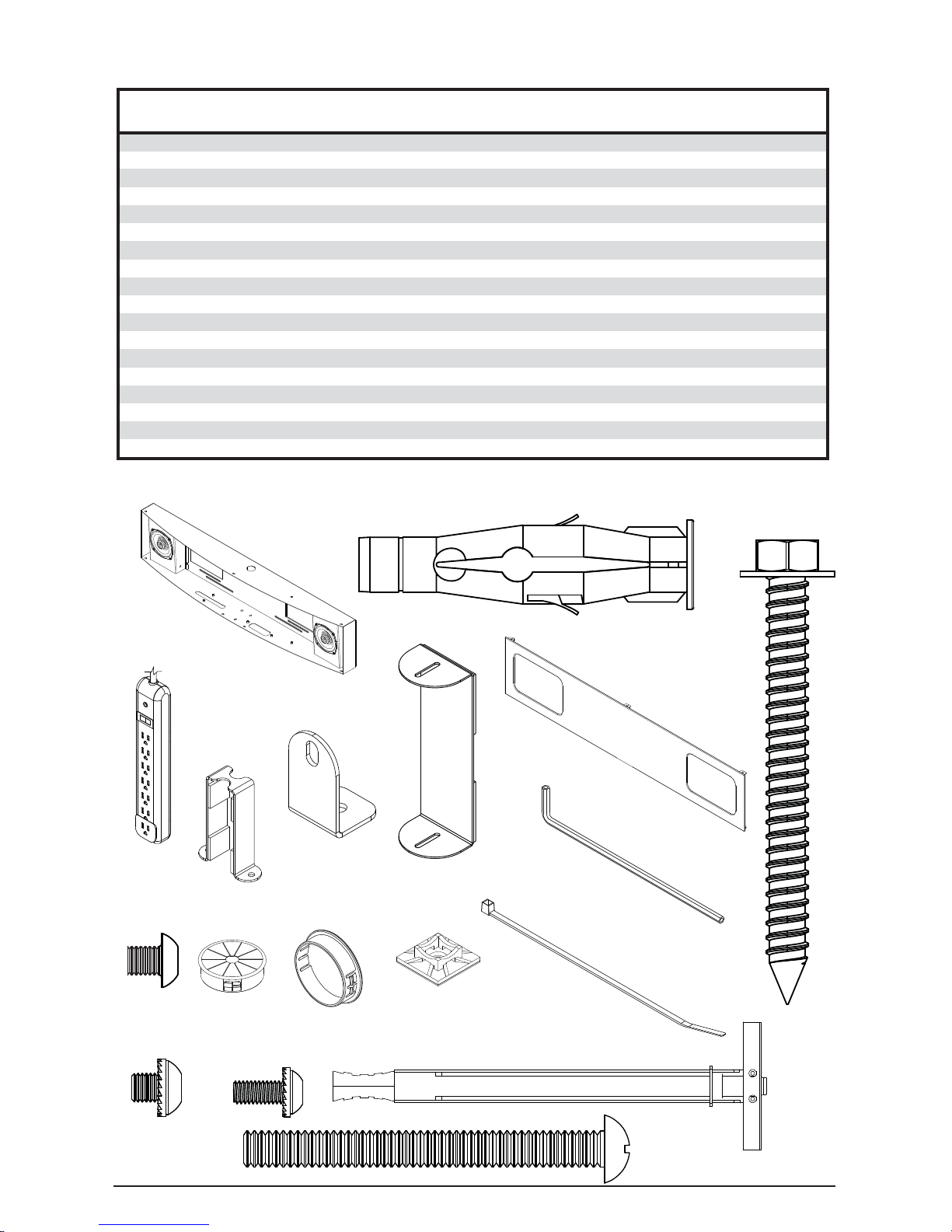
Before beginning, make sure you have all parts shown below.
O
N
P
D
E
F
H
G
J
K L
M
I
Q
R
C
B
A
Parts List
WL-AU-AVWS WL-AU-AVWS-W WL-AU-AVWSA WL-AU-AVWSA-W
Description Qty.
Part # Part # Part # Part #
A enclosure assembly 1 180-1201 180-2201 180-1201 180-2201
B 10mm concrete anchor 4 590-0321 590-0321 590-0321 590-0321
C 5/16" x 3" wood screw 4 520-1243 520-1243 520-1243 520-1243
D power strip 1 600-0100 600-0100 600-0100 600-0100
E receiver bracket assembly 1 180-1190 180-2190 — —
F amp bracket 2 180-1173 180-2173 180-1173 180-2173
G mic bracket 1 180-1189 180-2189 180-1189 180-2189
H cover assembly 1 180-1200 180-2200 180-1200 180-2200
I m5 x 6mm security screw 8 520-1114 520-2062 520-1114 520-2062
J cable bushing 2 590-1295 590-2295 590-1295 590-2295
K finishing cap 2 590-1123 590-2123 590-1123 590-2123
L cable tie anchor 3 600-0101 600-0101 600-0101 600-0101
M cable tie 3 560-9711 560-9711 560-9711 560-9711
N 4mm security allen wrench
1
560-9646 560-9646 560-9646 560-9646
O toggler 4 560-9708 560-9708 560-9708 560-9708
P 1/4"-20 x 2.5 phillips screw 4 520-9521 520-9521 520-9521 520-9521
Q m5 x 6mm serrated washer head security screw 6 510-1114 510-1114 510-1114 510-1114
R m4 x 10mm serrated washer head security screw 2 510-1060 510-1060 510-1060 510-1060
Page 5
5
ISSUED: 2012-10-11 SHEET #: 180-9041-2 2012-05-31
AA BB
KK LL
MM NN
CC DD EE FF GG
HH II JJ
AUDIO-REMOTE
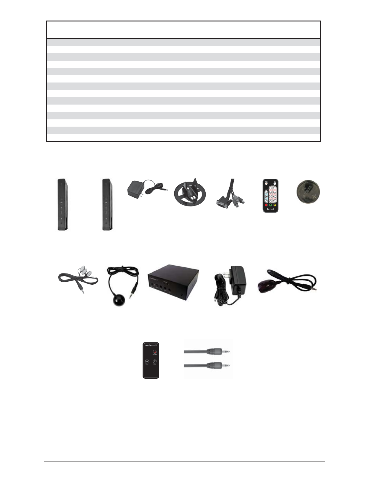
Parts List
WL-AU-AVWS WL-AU-AVWS-W WL-AU-AVWSA WL-AU-AVWSA-W
Description Qty.
Part # Part # Part # Part #
AA wireless transmitter hds-200
1
180-1002 180-1002 — —
BB wireless reciever hds-200
1
180-1003 180-1003 — —
CC power adapter - 12v 2a
2
180-1004 180-1004 — —
DD plastic stand for hds-200
2
180-1005 180-1005 — —
EE vga to rca adapter for hds-200
1
180-1006 180-1006 — —
FF remote controller for hds-200
1
180-1007 180-1007 — —
GG battery cr2025 3v
1
180-0008 180-0008 — —
HH ir flasher
1
180-1009 180-1009 — —
II ir-extender gen-2
1
180-0029 180-0029 — —
JJ amplifier, 25x2 - 2 input
1
180-1085 180-1085 180-1085 180-1085
KK amp kit 50w ac to dc power adapter 24v-2a
1
180-1088 180-1088 180-1088 180-1088
LL amp kit 50w ir extender eye, oval with tape
1
180-1089 180-1089 180-1089 180-1089
MM amp kit 50w card remote with battery
1
180-1090 180-1090 180-1090 180-1090
NN 3.5 audio cable
1
180-0192 180-0192 — —
Page 6
6
ISSUED: 2012-10-11 SHEET #: 180-9041-2 2012-05-31
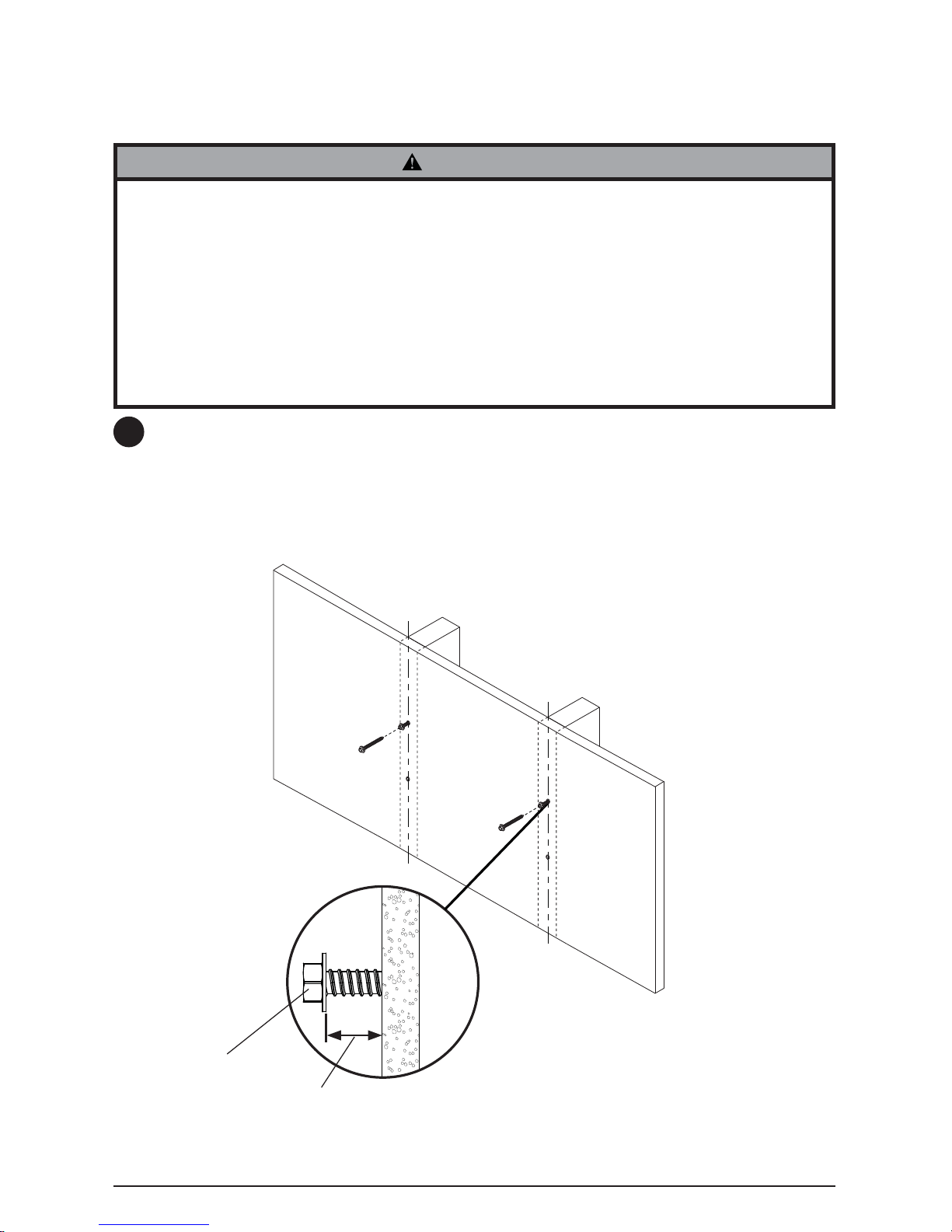
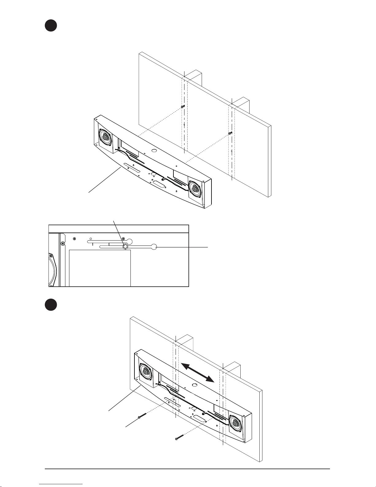
Use a stud fi nder to locate the edges of the studs and draw a vertical line down the center of
each stud. Place enclosure assembly (A) on wall. Level enclosure and mark center of four
mounting holes making sure that the mounting holes are on the stud centerlines. Drill four
3/16" (5mm) dia. pilot holes to a depth of 3" (76 mm). Insert two screws (C), leaving a 1/2" gap
between the screw head and the wall, as shown in fi g. 2.1.
fi g. 2.1
Installation to Double-Stud Wall
• Installer must verify that the supporting surface will safely support the combined load of the
equipment and all attached hardware and components.
• Tighten wood screws so that wall plate is fi rmly attached, but do not overtighten. Overtightening
can damage the screws, greatly reducing their holding power.
• Never tighten in excess of 80 in. • lb (9 N.M.).
• Make sure that mounting screws are anchored into the center of the stud. The use of an "edge to
edge" stud fi nder is highly recommended.
• Hardware provided is for attachment of mount through standard thickness drywall or plaster into
wood studs. Installers are responsible to provide hardware for other types of mounting situations
(not evaluated by UL).
WARNING
1
C
1/2"
(13mm)
Skip to page 8 for Metal Stud Installation.
Skip to page 10 for Concrete and Cinder Block Installation.
Page 7
7
ISSUED: 2012-10-11 SHEET #: 180-9041-2 2012-05-31
Position enclosure on wall. Install remaining two screws (C). Level enclosure assembly (A) and
tighten all screws.
A
A
C
Using the keyholes in the back of enclosure assembly (A), place enclosure assembly (A) on
to the two screws (C). Slide enclosure assembly (A) over until the mark on the wall plate lines
up with the center of the screw (C) as shown in detail A. NOTE: When mounting on 16" stud
centers, use bottom set of slots. For 20" and 24" stud centers, use top set of slots.
1
KEYHOLE
fi g. 2.2
fi g. 2.3
DETAIL A
C
1
Page 8
8
ISSUED: 2012-10-11 SHEET #: 180-9041-2 2012-05-31
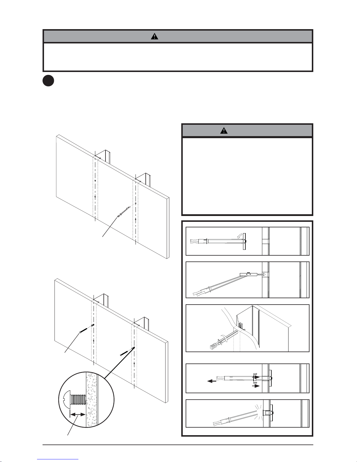
Use a stud fi nder to locate the edges of the studs and draw a vertical line down the center of
each stud. Place enclosure assembly (A) on wall. Level enclosure and mark center of four
mounting holes making sure that the mounting holes are on the stud centerlines. Drill four 1/2"
(13mm) dia. holes through drywall and metal studs. NOTE: It may be necessary to drill 5/32"
pilot holes prior to drilling 1/2" holes. Insert togglers (O) as shown in fi gure 2.4. Insert two 1/4"-
20 x 2.5" phillips screws (P), leaving a 1/2" gap between the screw head and the wall, as shown
in fi g. 2.5.
Installation to Metal Stud Wall
• Drywall must be 1/2" or thicker, and metal stud must be 24 gauge or heavier.
• Installer must verify that the supporting surface will safely support the combined load of the
equipment and all attached hardware and components (Not Evaluated By UL).
WARNING
• Product must be mounted through drywall
that has a minimum thickness of 1/2" and
into metal studs, 24 gauge or heavier.
• Make sure that togglers are anchored into
the center of the studs as shown in fi gure
2.2. The use of an "edge to edge" stud
fi nder is highly recommended.
• This product is intended for indoor use only.
Use of this product outdoors could lead to
product failure and personal injury.
WARNING
1
fi g. 2.4
fi g. 2.5
1/2"
(13mm)
O
1
2
3
4
5
Pivot end of toggler (O).
Push into hole.
Rotate toggler (O) clockwise to wedge it against inside walls
of metal stud.
Slide plastic cap forward while pulling back fi rmly on ring.
Break off excess.
P
O
Page 9

9
ISSUED: 2012-10-11 SHEET #: 180-9041-2 2012-05-31
A
P
Using the keyholes in the back of enclosure assembly (A), place enclosure assembly (A) on to
the two 1/4"20 x 2.5" phillips screws (P) as shown in fi g. 2.6. Slide enclosure assembly (A) over
until the mark on the wall plate lines up with the center of the 1/4"20 x 2.5" phillips screws (P) as
shown in detail B. NOTE: When mounting on 16" stud centers, use bottom set of slots. For 20"
and 24" stud centers, use top set of slots.
1
KEYHOLE
fi g. 2.6
fi g. 2.7
DETAIL B
P
1
Position enclosure on wall. Install remaining two 1/4"20 x 2.5" phillips screws (P). Level
enclosure assembly (A) and tighten all screws.
A
Page 10

10
ISSUED: 2012-10-11 SHEET #: 180-9041-2 2012-05-31
Place enclosure assembly (A) on wall and
mark center of four mounting holes. Drill
four 3/8" (10 mm) dia. pilot holes to a depth
of 3" (76 mm). Insert anchors (B) into holes
fl ush with wall as shown (right). Insert two
screws (C), leaving a 1/2" gap between the
screw head and the wall, as shown in fi g.
2.8.
1
3
2
B
Drill holes and insert anchors (B).
Place enclosure (A) over anchors (B) and secure with screws
(C).
Tighten all fasteners.
A
B
C
concrete
surface
• When installing Peerless wall mounts on cinder block, verify that you have a minimum of
1-3/8" (35 mm) of actual concrete thickness in the hole to be used for the concrete anchors.
Do not drill into mortar joints! Be sure to mount in a solid part of the block, generally 1" (25
mm) minimum from the side of the block. Cinder block must meet ASTM C-90 specifi cations.
It is suggested that a standard electric drill on slow setting is used to drill the hole instead of a
hammer drill to avoid breaking out the back of the hole when entering a void or cavity.
• Concrete must be 2000 psi density minimum. Lighter density concrete may not hold concrete
anchor.
• Make sure that the supporting surface will safely support the combined load of the equipment
and all attached hardware and components.
• Tighten screws so that wall plate is
fi rmly attached, but do not overtighten.
Overtightening can damage screws,
greatly reducing their holding power.
• Never tighten in excess of 80 in. • lb (9
N.M.).
• Always attach concrete expansion
anchors directly to load-bearing concrete.
• Never attach concrete expansion anchors
to concrete covered with plaster, drywall,
or other fi nishing material. If mounting to
concrete surfaces covered with a fi nishing
surface is unavoidable (not evaluated
by UL), the fi nishing surface must be
counterbored as shown below. Be sure
concrete anchors do not pull away from
concrete when tightening screws. If
plaster/drywall is thicker than 5/8" (16
mm), custom fasteners must be supplied
by installer (not evaluated by UL).
WARNING
WARNING
1
Installation to Solid Concrete or Cinder Block
C
1/2"
(13mm)
CUTAWAY VIEW
INCORRECT CORRECT
wall
plate
wall
plate
plaster/
dry wall
plaster/
dry wall
concrete
concrete
fi g. 2.8
Page 11

11
ISSUED: 2012-10-11 SHEET #: 180-9041-2 2012-05-31
1
A
A
C
Using the keyholes in the back of enclosure assembly (A), place enclosure assembly (A) on
to the two screws (C). Slide enclosure assembly (A) over until the mark on the wall plate lines
up with the center of the screw (C) as shown in detail C. NOTE: When mounting on 16" stud
centers, use bottom set of slots. For 20" and 24" stud centers, use top set of slots.
1
Position enclosure on wall. Install remaining 2 screws (C). Level enclosure assembly (A) and
tighten all screws.
fi g. 2.10
fi g. 2.9
C
KEYHOLE
DETAIL C
Page 12

12
ISSUED: 2012-10-11 SHEET #: 180-9041-2 2012-05-31
If your power source is located outside of the enclosure (A), route the power cord from the
power strip through the hole in the top or bottom of enclosure (A). Push the power cord through
the bottom of the cable bushing (J). Push cable bushing (J) into hole in the enclosure (A). Plug
into power source. If your power source is located inside the enclosure, push fi nishing cap (K)
into top and bottom holes in the enclosure (A).
D
A
J
K
A
A
Install power strip (D) onto mounting screws inside of enclosure assembly (A).
2
3
Page 13

13
ISSUED: 2012-10-11 SHEET #: 180-9041-2 2012-05-31
Slide the receiver mounting bracket (E) over the HDS200 receiver (BB) as shown. Install
HDS200 receiver assembly into enclosure (A) using two M5 x 6mm screws (Q).
Install amp brackets (F) into enclosure (A) using two M5 x 6mm screws (Q).
Q
E
BB
A
F
A
Q
4
5
Continue to step 4 for WL-AU-PST600(-W), WL-AU-PST1200(-W), WL-AU-PST1600(-W) Models.
Skip to step 5 for WL-AU-PST600A(-W), WL-AU-PST1200A(-W), WL-AU-PST1600A(-W) Models.
Page 14

14
ISSUED: 2012-10-11 SHEET #: 180-9041-2 2012-05-31
Install amp (JJ) between amp brackets (F) and secure using two M4 x 10mm screws (R) as
shown.
R
F
JJ
OPTIONAL. Install wireless mic receiver (not included) into area provided.
6
7
Page 15

15
ISSUED: 2012-10-11 SHEET #: 180-9041-2 2012-05-31
II
LL
A
K
Q
OPTIONAL. Secure mic receiver using mic bracket (K) and two M5 x 6mm screws (Q).
8
Install IR extenders to bottom of enclosure assembly (A) as shown. NOTE: Place double
sided tape included with IR extender (LL) to bottom of IR extender fi rst, then install to bottom of
enclosure assembly (A) as shown.
9
DOUBLE SIDED TAPE
NOTE: IR extender (II) is used on WL-AU-AVWS(-W) models only.
Page 16

16
ISSUED: 2012-10-11 SHEET #: 180-9041-2 2012-05-31
Route connector ends of IR extenders through holes in bottom of enclosure assembly (A) as
shown.
10
A
Page 17

17
ISSUED: 2012-10-11 SHEET #: 180-9041-2 2012-05-31
GAINAUX
MIC
IR IN
DCLAN
USB
COMPONENT-OUT
RECEIVER
AUDIO-OUTIR-INAV-OUTHDMI-OUT
Component Connections
II
H
BB
CC
LL
JJ
KK
NN
SPEAKERS
(PRE-WIRED)
TO MIC RECEIVER
(NOT INCLUDED.
SEE NEXT PAGE)
Use the following diagram to make the component connections. NOTE: For transmitter setup
instructions, refer to the Installation and Operation section of the HDS200 user manual.
(WL-AU-AVWS(-W)models only).
11
Page 18

18
ISSUED: 2012-10-11 SHEET #: 180-9041-2 2012-05-31
AMPLIFIER
GAINAUX
MIC
IR IN
AUDIO-REMOTE
Amplifi er
Main POWER Button (Unit)
Turns ON/OFF the unit’s main power. If the main power button on the unit is not turned on the unit
will not respond to remote control.
Note: If the power is turned OFF using the face button while the unit is in stand-by mode, and then
turned back on via the push button, the unit will remain in stand-by mode till the remote is used to
turn it on.
POWER Button (Remote Control) – The power button on the remote control allows toggling
between STAND-BY mode and power ON mode. In the STAND-BY mode the unit is not fully turned
off (the main push button turns the unit off completely and should only be pressed to turn ON the
unit during installation).
Indicator Light
Off – When the indicator light is not active the unit is OFF
Red – When the indicator light is red the unit is in STAND-BY mode. (Main Power Button (On Unit)
must be in the ON position)
Green – When the indicator light is green the unit is turned ON. (Main Power Button (On Unit) must
be in the ON position)
AUDIO INPUTS
Two stereo audio inputs include Auxiliary and Microphone connections. When using the
microphone (not included) it is recommended to use a mono to stereo adapter (not included).
VOLUME ADJUSTMENT (Unit and Remote Control)
Volume adjustment button on the unit or the remote control adjusts volume for the Auxiliary and
Microphone input simultaneously. The indicator light for volume adjustment will fl ash during volume
adjustment.
MODE SWITCH
The MODE Switch toggles between the units Stereo and Mono mode. When using the optional
Microphone capability with this unit it is recommended to use the MONO mode for best audio
results.
MIC GAIN ADJUSTMENT
The gain adjustment knob on the back of the unit goes from 0 (off) up to +10dB (at signal level)
over the Auxiliary input.
Page 19

19
ISSUED: 2012-10-11 SHEET #: 180-9041-2 2012-05-31
Amplifi er Setup
Connect the desired audio sources to the unit. Turn on the amplifi er using the Main Power
Button (NOTE: Remote control function will not work unless the unit Main Power has been
turned on). Ensure that the Power Indicator light is solid Green. Adjust volume to desired level.
Setup HDS200 transmitter and AV sources. (See HDS200 Quick Start Guide or User Manual for
instructions, WL-AU-AVWSA models only). Once complete, test audio from AV sources. Press
the vol+ and vol- arrows on the Amplifi er remote control. If using a PC as the audio source,
ensure headphone output is enabled and volume is at least half.
For Wireless Microphone setup, continue to step 14. Otherwise, skip to step 15.
Wireless Microphone Setup
When a wireless microphone system is installed, the relative gain to the HDS200 needs to be
set.
For fi xed level sources (Blu-Ray® player):
1. Play source with amplifi er volume at a comfortable level.
2. Adjust mic gain the the back of the amplifi er while talking into the microphone to allow
vocals to be slightly louder than the fi xed source volume.
3. Confi rm no feedback or "mic hotness" is present at high amplifi er volumes.
4. Fine tune as necessary.
12
13
14
Attach cover assembly (H). Install seven M5 x 6mm screws (I). Remove protective fi lm from
cover assembly (H).
I
H
15
PROTECTIVE FILM
(REMOVE)
For variable level sources (PC):
1. Set variable source level at 25%.
2. Adjust mic gain on the back of the amplifi er while talking into the microphone to allow
vocals to be slightly louder than the variable source volume.
3. If at max mic gain on amplifi er, and the microphone is not loud enough, lower variable
source volume and repeat adjustment steps.
4. Confi rm no feedback or "mic hotness" is present at high amplifi er volumes.
5. Fine tune as necessary.
Page 20

This page intentionally left blank.
Página en blanco.
Cette page a été laissée en blanc intentionnellement.
Diese Seite wurde absichtlich freigelassen.
Deze pagina is met opzet blanco gelaten.
Pagina lasciata intenzionalmente vuota.
Tato strana je záměrně prázdná.
Táto strana je zámerne prázdna.
Esta página foi intencionalmente deixada em branco.
Bu sayfa özellikle boş bırakılmıştır.
ENG
ESP
FRN
DEU
NEL
ITL
ČEŠ
SLK
POR
TÜR
Page 21

21
ISSUED: 2012-10-11 SHEET #: 180-9041-2 2012-05-31
Product
Mounts
Furniture
Cables
Cleaning Products
Electronic Products and components
Warranty Period
5 years
1 year
25 years
1 year
1 year
Peerless Industries, Inc. (“Peerless-AV
®
”) warrants to original end-users of Peerless-AV® products that Peerless-AV® products will be
free from defects in material and workmanship, under normal use, for the periods listed below, from the date of purchase by the original
end-user. At its option, Peerless-AV® will repair or replace with new or refurbished products or parts, or refund the purchase price of any
Peerless-AV® product which fails to conform with this warranty.
In no event shall the duration of any implied warranty of merchantability or fi tness for a particular purpose be longer than the
period of the applicable express warranty set forth above. Some states do not allow limitations on how long an implied warranty lasts,
so the above limitation may not apply to you.
This warranty does not cover damage caused by (a) service or repairs by the customer or a person who is not authorized for such service
or repairs by Peerless-AV
®
, (b) the failure to utilize proper packing when returning the product, (c) incorrect installation or the failure
to follow Peerless-AV®’s instructions or warnings when installing, using or storing the product, or (d) misuse or accident, in transit or
otherwise, including in cases of third-party actions and force majeure. This warranty also does not cover corrosion or rust resulting from
damaged, scratched or chipped paint or other surfaces.
In no event shall Peerless-AV
®
be liable for incidental or consequential damages or damages arising from the theft of any
product, whether or not secured by a security device which may be included with the Peerless-AV® product. Some states do not
allow the exclusion or limitation of incidental or consequential damages, so the above limitation or exclusion may not apply to you.
This warranty is in lieu of all other warranties, express or implied, and is the sole remedy with respect to product defects. No dealer,
distributor, installer or other person is authorized to modify or extend this Limited Warranty or impose any obligation on Peerless-AV
®
in
connection with the sale of any Peerless-AV® product.
This warranty gives specifi c legal rights, and you may also have other rights which vary from state to state.
LIMITED WARRANTY
Page 22

This page intentionally left blank.
Página en blanco.
Cette page a été laissée en blanc intentionnellement.
Diese Seite wurde absichtlich freigelassen.
Deze pagina is met opzet blanco gelaten.
Pagina lasciata intenzionalmente vuota.
Tato strana je záměrně prázdná.
Táto strana je zámerne prázdna.
Esta página foi intencionalmente deixada em branco.
Bu sayfa özellikle boş bırakılmıştır.
ENG
ESP
FRN
DEU
NEL
ITL
ČEŠ
SLK
POR
TÜR
Page 23

This page intentionally left blank.
Página en blanco.
Cette page a été laissée en blanc intentionnellement.
Diese Seite wurde absichtlich freigelassen.
Deze pagina is met opzet blanco gelaten.
Pagina lasciata intenzionalmente vuota.
Tato strana je záměrně prázdná.
Táto strana je zámerne prázdna.
Esta página foi intencionalmente deixada em branco.
Bu sayfa özellikle boş bırakılmıştır.
ENG
ESP
FRN
DEU
NEL
ITL
ČEŠ
SLK
POR
TÜR
Page 24

Peerless-AV
2300 White Oak Circle
Aurora, IL 60502
Email: tech@peerlessmounts.com
Ph: (800) 865-2112
Fax: (800) 359-6500
www.peerless-av.com
© 2012, Peerless Industries, Inc.
 Loading...