

PEERLESS WBV SERIES, WV SERIES, WBV-03-08, WBV-03-110, WBV-04-095 Installation, Operation & Maintenance Manual
...Page 1
WBV/WV
Boilers
Installation,
Operation
Maintenance
Manual
PEERLESS"
CAST IRON BOILERS
Page 2

Packaged or Knockdo ,
8 Sizes 3-5 Sections .60 to 2.00 GPH Input 82% to 86% AFUE
Natural Draft (chimney) Venting
Factory Assembled Sections on Knockdown Boilers
• Reduces Installation Time
WBV in 3 and 4 Section for Hot Water or Steam
• Convertible from Rear to Top Flue for Venting Flexibility
WV in 5 Section for Hot Water
• Top Flue Only
High Efficiency Flame Retention Burners
• Choice ofBeckett, Carlin or Riello
Full Plate Swing-Out Door
• Standard on All Boilers
• Provides Easy Access to Combustion Chamber Area
jbr Cleaning and Servicing
Large Water Content, Wet Base Section Design
• Reduces On/O_'f'Cycling
Steel Push Nipples
• Provide a Permanent Water Tight Seal Between Sections
• Unaffected by Petroleum and Other Contaminants
Deluxe Insulated Enameled Steel Jacket
• Reduces Boiler Heat Loss
Safety Controls
• Prob_ or Floai Type Low Water
Cut-Qff Approved on Steam Boilers
Tankless Coils
• For Domestic Hot Water Production
on Hot Water Boilers
As an ENERGY STAR _ Partner Peerless Healer Comparl¥ Has delerr#med
that certain f_rin9 rales of this product mee_ Ihe ENERGY STAR" guidelines
for energy efficiency
• Honeywell Operating Controls
• Taco 007 Circulator on Packaged Water Boilers
• Probe Type LWCO on Packaged Steam Boilers
omp\e te J
• Tankless Coils
• Barometric Draft Damper
• Grundfos Circulator on Packaged Water Boilers
• Float Tltpe LWCO on Packaged Steam Boilers
/'_'<'rl(,._.s 1 lec_ttq Compony is p&_a.s_d lo q[]_'r otlt _ @the" most coml)reh_.t_siv¢" u,tu_c_ttty l)i-o()l(lms ill
the. hlHztstry. All P(x'rless tz!sidential cckst iron boilers i11chtde a.fidl orl(! !F.ar It,azTcUlty. A limiled.
li]_'litllt" It,(tt r(iNly is provided jbr Ihe cc_st iron sections q[ Pcerless rt_sidetltial hol [t,(llt_!t boilet_.
P_'_tl('._5 _tl._o i)tol,id<!s o linlit_'d. 11!11_](fOf [tl_UTO/l/t] Oil I_l(_ C€ISt irotl SeCtiotls Q[ il5 I'('si_lt,llllol sl(?at]l
boil_'t._. Fit,(, ariel !('n !j('cw _5\'l_!lld('d [t,olv_lltli('s oil parts €Old lclbor nre IIOIL! (Ip(lilflblt'. P[('_Is_' COllStll/
]_'('rl_'y;5 [ It'(tlt,r ('OmlXUl!lJbr compIt'lt" tt,(ltT_ttll[I il!fbrmation.
PEGRLESS _
CAST IRON BOILERS
Peerless Heater Company * 231 North Walnut Street • Boyertown, PA 19512-1021 * 610-367-2153 • www.peerless-heater.com
FAB WBV RI (5!02 5M)
prlrlf(?(l _rl U S A
Page 3
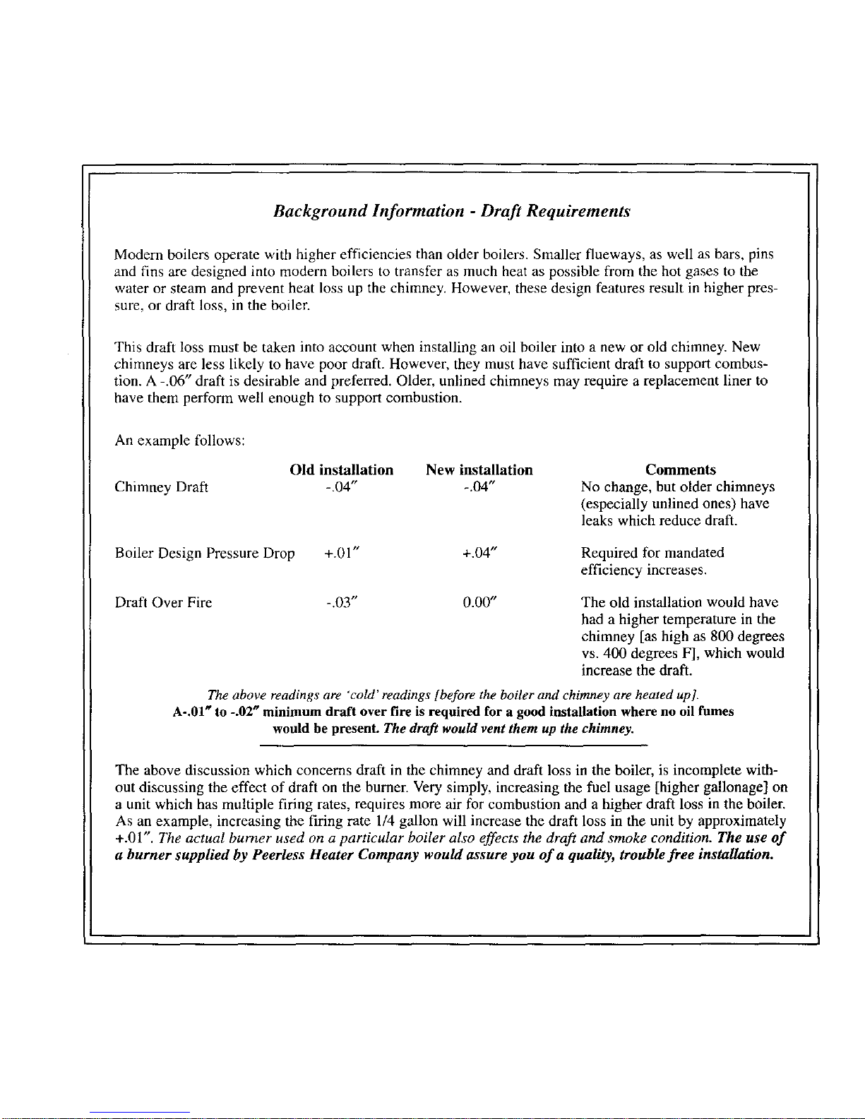
Background Information - Draft Requirements
Modern boilers operate with higher efficiencies than older boilers. Smaller flueways, as well as bars, pins
and fins are designed into modern boilers to transfer as much heat as possible from the hot gases to the
water or steam and prevent heat loss up the chimney. However, these design features result in higher pres-
sure, or draft loss, in the boiler.
This draft loss must be taken into account when installing an oil boiler into a new or old chimney. New
chimneys are less likely to have poor draft. However, they must have sufficient draft to support combus-
tion. A -.06" draft is desirable and preferred. Older, unlined chimneys may require a replacement liner to
have them perform well enough to support combustion.
An example follows:
Chimney Draft
Old installation New installation
-.04" -.04 °
Comments
No change, but older chimneys
(especially unlined ones) have
leaks which reduce draft.
Boiler Design Pressure Drop
+.01" +.04"
Required for mandated
efficiency increases.
Draft Over Fire -.03" 0.00"
The old installation would have
had a higher temperature in the
chimney [as high as 800 degrees
vs. 400 degrees F], which would
increase the draft.
The above readings are 'cold' readings [before the boiler and chimney are heated up].
A-.01 _ to -.02 _ minimum draft over fire is required for a good installation where no oil fumes
would be present. The draft would vent them up the chimney.
The above discussion which concerns draft in the chimney and draft loss in the boiler, is incomplete with-
out discussing the effect of draft on the burner. Very simply, increasing the fuel usage [higher gallonage] on
a unit which has multiple firing rates, requires more air for combustion and a higher draft loss in the boiler.
As an example, increasing the firing rate 1/4 gallon will increase the draft loss in the unit by approximately
+.01". The actual burner used on a particular boiler also effects the draft and smoke condition. The use of
a burner supplied by Peerless Heater Company would assure you of a quality, trouble free installation.
Page 4
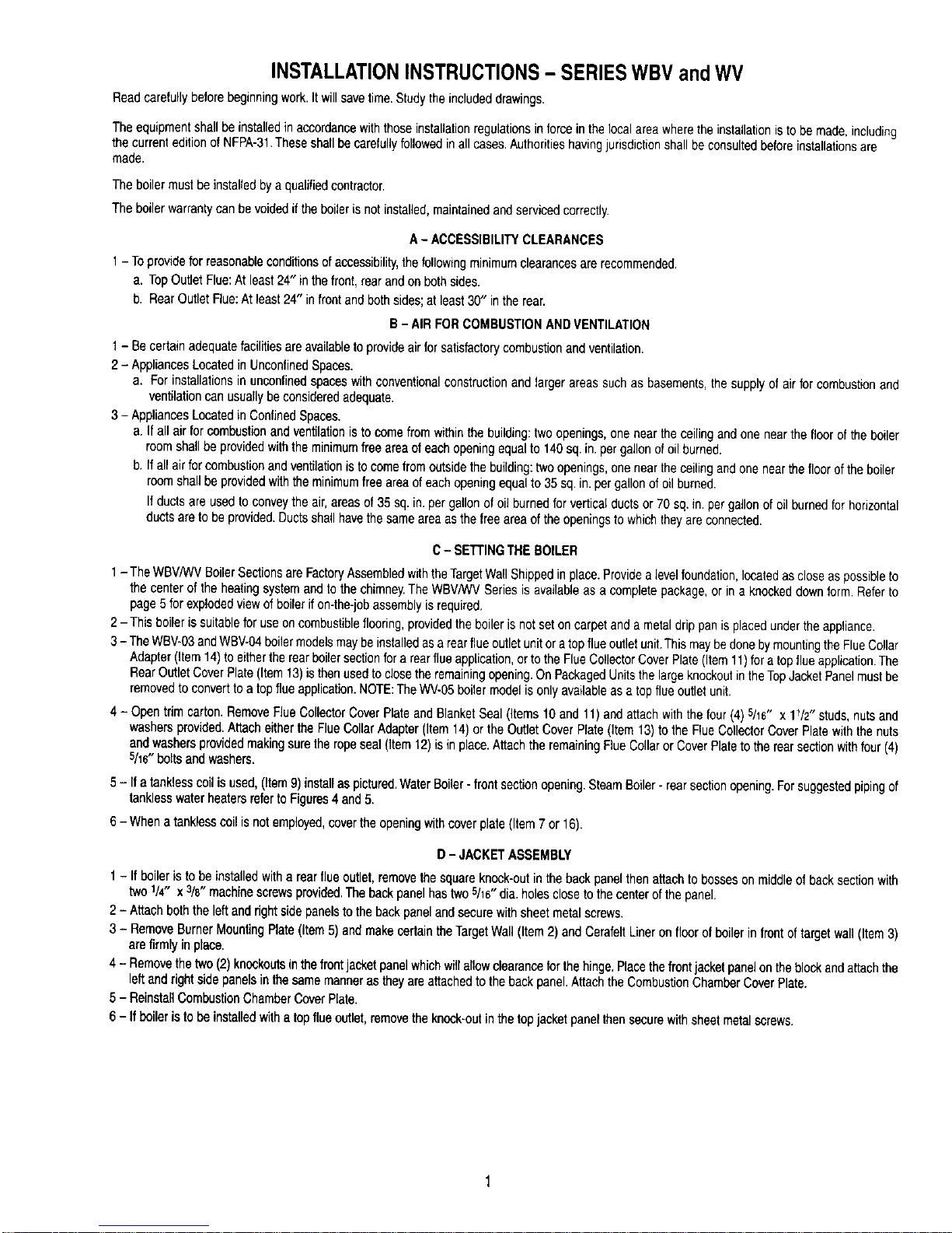
INSTALLATIONINSTRUCTIONS- SERIESWBVandWV
Readcarefullybeforebeginningwork.It willsavetime.Studytheincludeddrawings.
Theequipmentshallbeinstalledinaccordancewiththoseinstallationregulationsin forceinthe localareawherethe installationisto be made,including
the currenteditionof NFPA-31.Theseshallbecarefullyfollowedinall cases.Authoritieshavingjurisdictionshall beconsultedbeforeinstallationsare
made.
Theboiler mustbe installedbya qualifiedcontractor.
Theboiler warrantycanbe voidedifthe boileris notinstalled,maintainedandservicedcorrectly.
A - ACCESSIBILITYCLEARANCES
1- Toprovidefor reasonableconditionsofaccessibility,thefollowingminimumclearancesarerecommended.
a. TopOutletFlue:At least24" in thefront,rear andon bothsides.
b. RearOutletFlue:At least24" infrontand bothsides;at least30" inthe rear.
B- AIRFORCOMBUSTIONANDVENTILATION
1- Be certainadequatefacilitiesareavailableto provideairforsatisfactorycombustionand ventilation.
2 -Appliances Locatedin UnconfinedSpaces.
a. Forinstallationsin unconfinedspaceswith conventionalconstructionand larger areassuchas basements,the supplyof airfor combustionand
ventilationcan usuallybe consideredadequate.
3 - AppliancesLocatedin ConfinedSpaces.
a. If all airfor combustionandventilationis to come fromwithinthe building:twoopenings,onenearthe ceilingand one nearthe floor of the boiler
roomshallbe providedwiththe minimumfree areaof eachopeningequalto 140sq. in. pergallonof oilburned.
b. If allairfor combustionandventilationisto comefromoutsidethe building:twoopenings,onenearthe ceilingandone nearthefloorofthe boiler
roomshallbeprovidedwiththe minimumfreeareaof eachopeningequalto 35 sq.in. pergallonof oil burned.
If ductsare usedto conveythe air,areasof 35 sq. in.pergallon ofoil burnedfor verticalductsor 70 sq.in.pergallonof oil burnedforhorizontal
ductsaretobe provided.Ductsshallhavethesameareaasthe freeareaof theopeningsto whichtheyare connected.
C- SETTINGTHE BOILER
1- TheWBV/WVBoilerSectionsare FactoryAssembledwiththeTargetWallShippedinplace.Providealevelfoundation,locatedas closeas possibleto
the center of the heatingsystemandtothe chimney.TheWBV/WVSeries is availableasa completepackage,or in a knockeddownform. Referto
page5 for explodedviewof boilerif on-the-jobassemblyisrequired.
2-This boileris suitableforuseon combustibleflooring,providedtheboiler is not setoncarpetand a metal drippan isplacedunderthe appliance.
3- TheWBV-03andWBV-04boilermodelsmaybe installedas a rearflueoutletunit ora topflue outletunit.This maybedonebymountingthe FlueCollar
Adapter(Item14)to eithertherear boilersectionfora rearflueapplication,orto the FlueCollectorCoverPlate(Item11)fora topflueapplication.The
RearOutletCoverPlate(Item13) isthenusedto closetheremainingopening.OnPackagedUnitsthe largeknockoutintheTopJacketPanelmustbe
removedtoconvertto a topflue application.NOTE:TheWV-05boilermodelisonlyavailableasa top flueoutletunit.
4- Open trim carton.RemoveFlueCollectorCoverPlateandBlanketSeal(Items10 and 11)and attachwith thefour (4)5/16" x 1_/2"studs,nutsand
washersprovided.Attacheitherthe FlueCollarAdapter(Item14)or the OutletCoverPlate(Item 13)to the FlueCollectorCoverPlatewiththe nuts
andwashersprovidedmakingsurethe ropeseal(Item12)is in place.Attachthe remainingFlueCollaror CoverPlatetothe rearsectionwithfour(4)
5/r6"bolts andwashers.
5- If a tanklesscoilisused,(Item9)installaspictured.WaterBoiler- frontsectionopening.SteamBoiler- rearsectionopening.Forsuggestedpipingof
tanklesswaterheatersreferto Figures4 and5.
6- Whena tanklesscoilis notemployed,covertheopeningwithcoverplate(Item 7 or 16).
D- JACKETASSEMBLY
1- If boiler is tobe installedwitharear flueoutlet,removethesquareknock-outinthe backpanelthenattachtobosseson middleof backsectionwith
two1/4" x 3/8"machinescrewsprovided.The backpanelhas two 5/16"dia.holesclosetothe centerofthe panel.
2 - Attach boththe left and rightsidepanelstothe backpanel andsecurewithsheetmetalscrews.
3 - RemoveBurnerMountingPlate (Item5) andmakecertainthe TargetWall(Item2) and CerafeltLineron floorofboilerin frontoftarget wall(Item3)
arefirmly in place.
4- Removethetwo(2)knockoutsinthefrontjacketpanelwhichwill allowclearanceforthe hinge.Placethefrontjacketpanelonthe blockandattachthe
leftand rightsidepanelsin the samemannerastheyareattachedto thebackpanel.Attachthe CombustionChamberCoverPlate.
5- ReinstallCombustionChamberCoverPlate.
6- If boiler is to be installedwitha top flueoutlet,removetheknock-outinthe topjacketpanelthensecurewith sheetmetalscrews.
Page 5
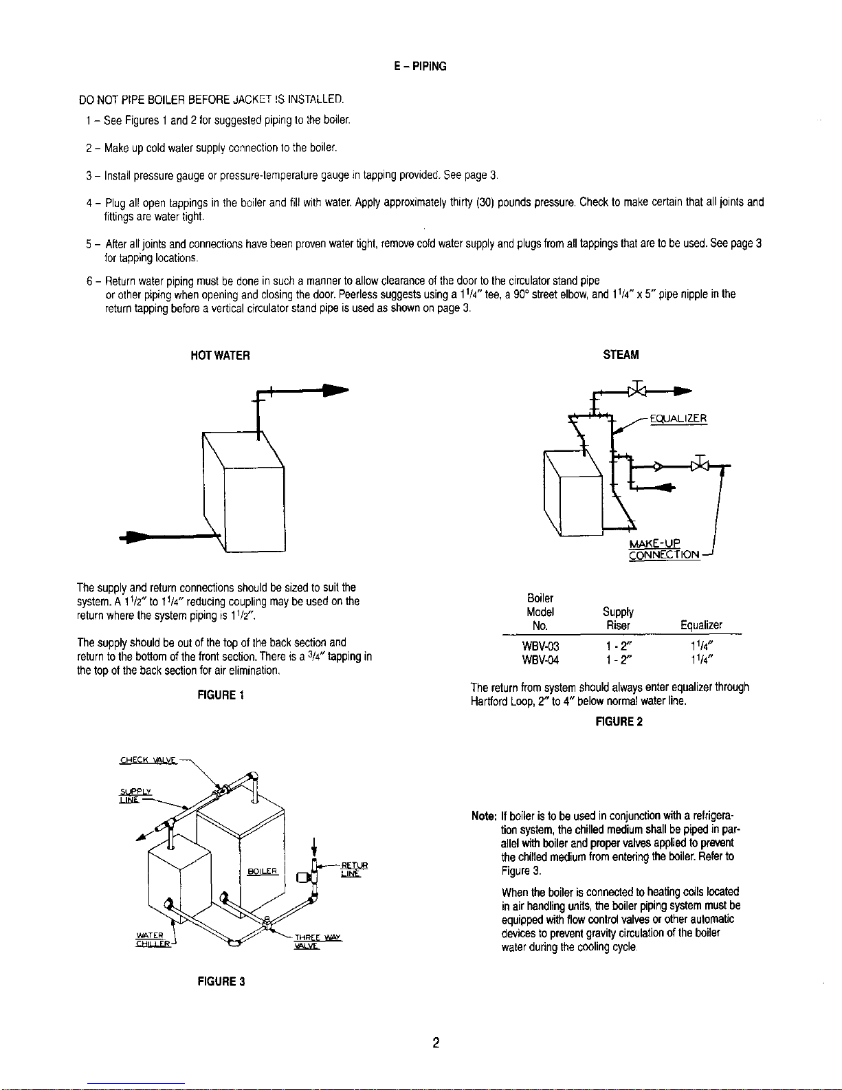
E - PIPING
DONOTPIPEBOILERBEFOREJACKET_SINSTALLED.
1- See Figures1 and2 forsuggestedpipingtothe boiler.
2- Makeupcold watersupplyconnectiontothe boiler.
3- Installpressuregaugeor pressure-temperaturegaugein tappingprovided.See page3.
4- Plugal_opentappingsin the boilerandfill with water.Applyapproximatelythirty (30) poundspressure.Checkto make certainthat all iointsand
fittingsarewatertight.
5- Afteralljoints andconnectionshavebeenprovenwatertight,removeooldwatersupplyandplugsfromalltappingsthataretobe used,Seepage3
fortappinglocations.
6- Returnwater pipingmustbe donein sucha mannertoallowelearaooeofthe doortothe circulatorstandpipe
orother pipingwhenopeningandclosingthedoor.Peerlesssuggestsusinga 11/4"tee,a90° streetelbow,and 11/4"x 5" pipenippleinthe
returntappingbeforea verticalcirculatorstandpipeis usedas shownon page3.
HOTWATER
v
Thesupplyand returnconnectionsshouldbe sizedto suitthe
system.A 1r/2" to 11/4" reducingcouplingmaybeusedon the
returnwherethe systempipingis 11/2".
Thesupplyshouldbe outof thetop ofthe backsectionand
returnto thebottomofthe frontsection.Thereisa 3/4"tappingin
the top oftheback sectionfor airelimination,
FIGURE1
STEAM
Boiler
Model Supply
No. Riser Equalizer
WBV-.03 1-2" 11/4"
WBV-04 1- 2" 11/4"
Thereturnfromsystemshouldalwaysenterequalizerthrough
HartfordLoop,2" to 4" belownormalwaterline,
RGURE2
_TER
FIGURE3
Note:If boileris to be usedinconjunctionwitha refrigera-
tionsystem,thechilledmediumshallbepipedin par-
allelwithboilerandpropervalvesappliedtoprevent
thechimedmediumfromenteringtheboiler.Referto
Figure3.
Whentheboilerisconnectedtoheatingcoilslocated
inairhandlingun_S,the boilerpipingsystemmustbe
equippedwithflowcontrolvalvesor otherautomatic
devicestopreventgravitycirculationof theboiler
waterduringthe coolingcycle.
Page 6
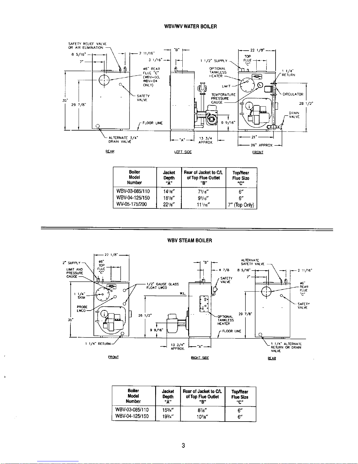
WBV/WVWATERBOILER
SAFETY RELIEF VALVE
.35" VALVE
DRAIN VALVe"
--2 11/16"
3 1/16" _
• 6" REAR
FLUE "C"
_(WBV-O3,
WBV-04
ONLY)
LINE
R_
1
1 I/2" SUPPLY_
OPTIONAL
TANKLESS
HEATER x
LIMIT -
TEMPERATURE
PRESSURE
GAUGE _'
1_3/_ I_-
APPROX '
-_-_2,18"7
1 114"
' "C'"DOLATO"
28 I/2"
DRAIN
VALVE
FRONT
Boiler Jacket RearofJackettoC/L Top/Rear
Model Depth ofTopFlueOutlet FleaSize
Number "A.... B.... C"
WBV-03-085/110 141/8" 71h6" 6"
WBV-04-1251150 18%" 91h6" 6"
WV-05-175/200 22%" 111116" 7" (TopOnly)
WBVSTEAMBOILER
SKIM
PROBE
FLOAT LWCO
[
ALTERNATE
29 7/8"
_OP_ONAL
TANKLESS J
HEATER
-FLOOR LINE
_2 11/16"
_6"
_REAR
FLUE
-C-
'_SAFETY
VALVE
1 I/4" ALTERNATE
RETURN OR DRAIN
VAL'AE.
g_
Boiler
Model
Number
Jacket Rear of Jacketto C/L Top/Rear
Depth of Tap FleaOutlet Flue Size
"A.... B" "C"
WBV-03-085/110 153/4" 87/8" 6"
WBV-04-125/150 19314" 10%" 6"
3
Page 7

HIGH TEMPERATURE
HOT
MIXED
MIN.
WATER
MIXER
HEATER
V4" CONTROl_
"TAPPING
CONTROL
HIC.H TCMPCRATUR_"
HEATER
i2 _ MiN°
3/4" CONTROL
FLOW
INLET
COLD WATER
INLET
FIGURE4 FIGURE5
7-Tankless WaterHeater
Whenwaterheateris not employed,coverthe heateropeningwith coverplate(Item7or 16)
BESURERUBBERGASKETIS IN PLACEBETWEENCOVERPLATEORWATERHEATERPLATEANDBOILERSECTION.
8- StorageTankHeater- if awaterboileristo beusedin conjunctionwithastoragetankheaterreferto Figure6fortypicalpiping.Alsorefertoadditional
instructionssuppliedwith tank,
THREE WAY VALVE
DOMESTIC HOT
WATER SUPPLY
SYSTEM
RETURN
SYSTEM
BOILER
FIGURE6
INTERNAL
CO_L_
fCOLDWATER
SUPPLY
DOMESTIC HOT WATER
ST0f_AC-.,_:TANK
DANGER:INSTALLANTI-SCALDDEVICEINHOT WATERSUPPLYPIPING.WATERTEMPERATUREABOVE125°FCANCAUSESEVEREBURNS
INSTANTLYOR DEATHFROMSCALDS.
Page 8

FIGURE7:STEAMBOILERS
FIGURE8:WATERBOILERS
(Seepage 13for partsidentification)
Page 9

F-OILBURNERINSTALLATION
1-The oil burneris suppliedwitha mountingflangefixedin position.
2- Mounttheburnertothe combustionchambercoverplate(Item5) withfour(4)5/r6"studsand nutsprovided.
BESUREHITEMPGASKETISBETWEENTHE BURNERMOUNTINGFLANGEAND THECOMBUSTIONCHAMBERCOVERPLATE.
3- Caremustbe takenwhen routingtheoil lines so notto interferewith theopeningandclosingofthe door.Flexibleoillinesor flaredcopperdiscon-
nectswithvalves(whencopperlinesare used)maybeinstalledto assurefullopeningofthe doorwhenservicing.
4- Oil BurnerSpecifications:
Forinformationpertinenttothe oilburnersuchas nozzlesizing,fuelsupplypiping,adjustingor servicing,referto thechartsbelowand theinstalla-
tion manualaccompanyingthe burner.
BECKETTBURNERWITH140 PSI PUMPPRESSURE
Boiler Burner Burner Static Nozzle Start-UpSettings Head
ModelNo, ModelNo. Head Plate Size AirShutter AirBand Setting
WBV-03-085 AFG-F3* F3 33/8" 0.7580" B HAGO 6.0 1 N/A
WBV-03-110 AFG-F4 F4 33/8" 0.9080° BHAGO 6.0 0 N/A
WBV-04-095 AFG-F4 F4 33/8" 0.85800B DEL 6.0 0 N/A
WBV-04-125 AFG-F4 F4 33/8" 1.10800B HAGO 5.0 2 N/A
WBV-04-150 AFG-F6 F6 23/4" 1.25800B HAGO 8.0 1 N/A
WV-05-175 AFG-MV1 V-1 1.5060° BHAGO 10.0 3 3
WV-05-200 AFG-MV1 V-1 1.7560° BHAGO 10.0 9 3
*RequiresLowF_ringRateBaffle
WAYNEBURNERWITH100PSIPUMPPRESSURE
Boiler Burner AirCone Nozzle** Start-UpSettings
ModelNo, ModelNo, I,D. Size FlameLock Off-CycleDamp, AirShutter
WBV-03-085 HS 21/2" NoHoles 0.8580° B 1 t.0 0.50
WBV-03-110 HS 21/2"NoHoles 1.1080" B 1 2.0 1.50
WBV-04-125 HS 21/2"6 Holes 1.25 80°B 1 2.0 1.75
WBV-04-150 HS 21/2,,6 Holes 1.5080°B 1!/2 2.0 2.00
WV-05-175 HS 21/2"6 Holes 1.7580° 8 3 2.0 2,25
WV-05-200 HS 21/2"6 Holes 2.0080° B 5 2.0 2.50
** DelavanRecommended
CARLIN99FRDOILBURNERWITHMODEL98022PSCMOTOR
Boiler Burner Start-UpSettings
ModelNo. ModelNo. AirShutter NozzleSize PumpPressure HeadDim.A AirBand
WV-05-175 99FRD Open 1.50x600BHAGO 150PSi 5 10%open
WV-05-200 99FRD Open 1.65x 600B HAGO 150PSI 5 45%open
CARLINEZ-1HPOIL BURNERWITHMODEL98022PSCMOTOR
Boiler Burner Start-UpSettings
ModelNo. ModelNo. AirShutter NozzleSize PumpPressure AirBand HeadBar
WBV-03-085 EZ-IHP Blank 0.65x 70°ADEL 150PSI 0.60 0.60- 0.65
WBV-03-f10 EZ-1HP Blank 0.85x 700ADEL 150 PSI 0.65 0.85- 1.00
WBV-04-095 EZ-1HP Blank 0.75 x 70° A.DEL 150 PSI 0.60 0.75
WBV-04-125 EZ-1HP Blank 1.00x 700ADEL 150PSI 0.85 0.85- 1.00
WBV-04-150 EZ-1HP Blank 1.25x 60° B DEL 150PSI 1.00 1.10- 1.25
NOTE:Start-upandAdjustmentRecommendations...AdjustburnerforhighestCO2 (Maximum13%)whilemaintaininga0 Smokeand
-.01to -.02" W.C.OverfireDraft.Alladjustmentsmustbe madeusingsuitableinstrumentssuchasfoundin a8acharachCombustion
TestKit.
6
Page 10

F - OIL BURNERINSTALLATION(continued)
RIELLOSERIES40OIL BURNER
Boiler Burner Nozzle** Pump Turbulator AirDamper
ModelNo. ModelNO. Size Pressure Setting Setting
WBV-03-060 F3 0.50 90°B 145 0.0 2.9
WBV-03-085 F5 0.65 60" W 170 1.0 2.45
WBV-03-110 F5 0.85 60°W 165 2.5 2.8
WBV-04-125 F5 1.0060°W 155 25 3.4
WBV-04-140 F5 1.1060° W 160 4.0 4.2
WV-05-175 F10 1.3560"B 165 2.0 2.5
WV-05-200 F10 1.5060° B 170 2.5 2.8
** DelavanRecommended
NOTE:AboveTurbulatorandAir DamperSetlingsare start-upsettings only. Finaladjustmentsmustbe madewithcombustiontestinstruments.
ADVERSEFUELCONDITIONS
Ifanadversefuelconditionsuchascoldoilexists,itmaybeneces-
sarytoincreasethepumppressuretothenozzle.Coldoilis much
hardertoatomizeat 100psicomparedto roomtemperatureoil.Tothe
rightis a chartgivingflowrates ofstandardnozzlesizesat120 psi
and140psi pumppressure.
Note:If itwasnecessarytoincreasethepumppressureabovethe
standard100psi,toeliminateanyconfusionforthenextroutine
servicinga tagmustbeplacedontheburnerindicatingpump
pressureandnozzlesizeused.
Approx.NozzleRatesGPH
NozzleRating
At100 PSI 120PSI 140 PSI
0.50 0.55 0.59
0.65 0.71 0.77
0.75 0.82 0.89
0.85 0.93 1.00
0.90 0.99 1.07
1.00 1.10 1.18
1.10 1.21 1.30
1.20 1.31 1.41
1.25 1.37 1.48
1.35 1.48 1.60
1.50 1.64 1.78
1.65 1.81 1.95
1.75 1.92 2.07
G - CONTROLS
1- Applycontrolsas follows:
a. WaterBoilers:
Installthelimitoroperatingcontrol,pressure-temperaturegaugeandsafetyreliefvalve.Seepage3 for properlocation.
b. SteamBoilers:
Installlimit,pressuregauge,gaugeglasstrimandsafetyvalve.Seepage3.Forapplicationofprobelow-watercut-offsee
page3, andcontrolmanufacturersinstructionsheetshippedwiththecontrol.Whenprobe-typeLWCOisused,Peerlessrecommends
HydrofavelCG450.
2- Forcompleteinformationonservicingandadjustmentofcontrols,refertotheattachedcontrolspecificationsheets.
Caution:Pipethe dischargeofthe safetyvalveorreliefvalveto preventinjuryinthe eventofpressurerelief.Pipethedischargeto a drain.Provide
pipingthatis thesamesizeasthereliefvalve.
H-WIRING
1- All electricalwiringshallbe doneinaccordancewiththeNationalElectricalCodeand LocalRequirements.SinglePoleSwitchesincludingthoseof
SafetyControlsorProtectiveDevicesshallnotbewired ina groundedline.
2- Locatejunctionboxin thetrim carton.Mountjunctionboxto theholesin the rightside of jacketwith (2)#10 x 1"sheetmetalscrews.
3- Locatepolarizedharnessin thetrim carton.Connectharnessfromthejunctionboxto the limit (waterboilers)orlowwatercut-off(steamboilers).See
JunctionBoxdetail(Figure9),photos(Figure10& cover),and wiringdiagrams(Figures11-13).
7
Page 11

WARNING:Improperinstallationof burnerharnesscanallowburnerto energizewithswingdooropen,creatingasevereburnhazardtoboiler
maintenancepersonnel
4a - Locatethe polarizedburnerharnessin theburnercarton.Attachharnessbetweenburner andjunctionbox. SeeJunctionBoxdetail (Figure9),
photos(Figure10& cover),and wiringdiagrams(Figures11-13).
4b.- If using anon-Peerlesssuppliedburner,obtainappropriateburnerharnessfroma PeerlessDistributor,or hardwireburnersuchthat burnerswing
doorcannot beopenedwithoutdisconnectingpower.
Harnessfor Beckettor Cadinburner- 50232(polarized,21" longconduit)
Harnessfor Rielloburner- 50226(polarized,36" long conduit)
5 Wirezone circulatorsasshownin Figure14and zonevalvesas shownin Figure15
©©
FIGURE9 FIGURE10
p_,:,dr_ CONT_O. OI_,_R • {WJT)
J/oo_ _ • iis/qso/I
i ws_ FORCED HOT WATER
-- WtTH TANKLES_ HEATER
, - _ HONEYWELL L8124A OR L8124C
t'l_ *I, CO
WW_OUT TANKLESS HEATER
• _ HONEYWELL L8148A
cr_c_U_TO_
FIGURE11:WATERBOILERS
Page 12

w
Y
_GNITOR l
BURNER
LIMIT
CAD
F , , ,
OPERATING CONTROL
FOR STEAU W/
TANKLESS HEATI_R ONLy
BC4LER T GROUND
J/ BOX
_OUNO
SCREW _ J / _GROUNB
G O SCREW ADDITIONAL
<_ UMIT SAFETY S_ TCHES
i-1-,_=
LBURNER _ SER_C[ S_TCH
BI_NEBT _ (BY INSTAL_.[R)
STEAM WITH OR _ (HOT)
WITHOUTHEATERTANKLESS I _ L2L•_$5/60/I
FUSED DISCONNECT
(BY INSTALLER)
24v _HERMOSTAT
--LINE VOLTAGE
........... LOW VOLTACE
ALL VelRING MUST COMPLY "t_TH ApI_LIANCE COO_S, (_O_NANCE5 AND REGULATIONS
FIGURE12:STEAMWITHFLOATLOWWATERCUT-OFF
w
,{
OP_RATIN G CaN TROL
TANI_ESS _a_R I_ILy
R71_B OIJI_ER /
PRIMARY CONmOL BURNER
J/ BOX
IGNITOR 8_LER
_rED J/ BOX
H YDROtE',_ L
ROUND CG4_ O
BURNER SCREW pROB E LWC0
LI 8K K GROUND FUS/ED D4SCONNECT
LIM_T JUMPER _R_ lee S_TCH (HOT/
_ URN_ R CONTROL[] STEAM WITH OR
WITHOUT TANKLESS
t" / ", , SAFETY S_ITCPE5
: _ "_ ..... -_) 24v THERMOSTAT
__ LIN_ VOLTAG_
.......... LOW VOL T&GE
ALL _q_ING MUST [_OMPLY I_TH APPLIANC_ C(_S, (_NAN{_S ANO R_GU_AIIONS
FIGURE13: STEAMWITHPROBELOWWATERCUT-OFF
Page 13

LINE VOLTAGE
LOW VOLTAGE
CIRCULATOR
NOTE:
ALL WIPING MU_T COMPLY WITH APPLICABLE
CODES,ORDINANCES_AND REGULATIONS. ZONE #l ZONE _B ZONE _3
-.+ _
FIGURE14:ZONINGWITHCIRCULATORS
iBOV - 6OMZ
TO MAIN
DISCONNECT
12o/z4v SOHZ _
4OVA _LIL2 I I
I
BOX
©
II
i I
j I
I
I
I
I
I
I
J
ALL WIRING MUST COMPLY WITH APPLICAI__E
CODES I ORDINANCES t AND REGULATIONS .
FIGURE15:ZONINGWITHZONEVALVES
10
Page 14

L2 LI
TO PEERLESS
PARTNER C:RCULAiOR
_O ZONE ]
SPACE HE ATIN_
THERMOSTAT
TO MAIN ,r_-A _"
DISCONNECT
---(9
®
i LINE VOLTAGE
...... LOW VOLTAGE
BOILER LIMIT
HONEYWELL LB148A
TO BOILER TO BURNER
CIRCULATOR DISCONNECT
FIGURE16:PARTNERWITHCIRCULATOR(NON-PRIORITY)
I - CLEANINGTHESTEAMSIDE(SKIMMING)
Cleanthe boiler withinone week afterinitialstart-up.Cleaningwill be moreeffectiveif boileroperatesa dayor twoto loosensedimentandimpuritiesin
system.
Boilermustbecleanedto removeanyaccumulationofoil,grease,sludge,etc.insystem,Thesesubstancescan causefoamingandsurgingofboilerwater,
producingan unstablewaterline andwatercarryoverto system.
WARNING:CLEANINGTHEBOILERREQUIRESTHEUSEOFVERYHOTWATERANDCORROSIVECHEMICALS.USECAREWHENHANDLING
TOPREVENTINJURY.
1- Connecta skimvalveoffthe 11/,NPTskimtappingonfrontof boiler.SeeWBVsteamboilerfiguresonpage3 to locateskimtapping.Runa drain
lineoff skimvalveto a pointof safedischarge.
2- Providea meansof supplyingcontinuousfreshwatertothe boilerfor thecleaningprocess.
3- Openthe skim valve.Fillboileruntil waterbeginsto flow outofthe valve.
4- Usecommonwashingsoda,suchasArm andHammerSuperWashingSoda.Mix1/2 poundof sodawithwaterin a 10quart pail.Pourthemixture
intothe boilerthroughthe safetyreliefvalvetapping.
CAUTION:DONOTLEAVEBOILERUNATTENDEDWHILEFIRINGBURNER.OPERATINGBOILERWITHWATERBELOWMINIMUM
PERMISSIBLEWATERLEVELMAYFRACTURESECTIONS.
5- Turnon burner.Allowboilerwaterto heatup tojust belowsteaming(180- 200° F). Donot allowboilerto steam;steamingmixesupcontaminants
insteadoffloatingthematsurface.
6- Openmake-upwatervalvetocontinuouslyfeedwaterto boiler.Adjustflowto maintainwatertemperatureat 180- 200° E
CAUTION:DONOTALLOWMAKE-UPWATERTO FLOWTOOFAST.EXCESSIVEQUANTITIESOFCOLDWATERMAYFRACTURESECTIONS.
7- Continueskimmingboileruntilwaterflowingfromskimtappingflowsclear.This willtakesome time,possiblyseveralhoursforadirty system.
8- Turnoff burner,closemake-upwatervalve.
9- Drainboilercompletely.Refilland drainone or twotimestowashoutall washingsoda.
10- Removeskimvalveand piping.Install11/4NPTplugin skimtapping.
NOTE:IF GAUGEGLASSBECOMESDIRTYMORECONTAMINANTSHAVEWORKEDLOOSEIN SYSTEM.REPEATCLEANINGANDSKIMMING
PROCESSAS NEEDEDTO CLEANSYSTEM.
11
Page 15

J- CLEANINGHEATINGSURFACES
NOTE:BOILERISTO BECLEANEDATLEASTONCEA YEAR.TOTHOROUGHLYCLEANTHEBOILERITMUSTBEBRUSHEDDOWNFROMTHE
TOE ALTERNATELY,FOR LIMITEDSPACE OR MINIMUM CLEARANCETO COMBUSTIBLEINSTALLATIONS,CLEANINGTHE HEAT
EXCHANGERFROMTHE COMBUSTIONCHAMBERSIDEISACCEPTABLE.
TOCLEAN:
1 Turnoffall electricalpowertothe boiler beforebeginningcleaningoperation.
2- Removetopjacket paneland fluecollectorcoverplate,item 11.
3- Brushthe fluepassagesthoroughlyfromthetop witha wirebrush.Ifunitis extremelydirty,brushingupfromthe combustionchamberareaalsomay
be necessaryThetarget wall is madeofa softceramicfiber,caremustbe takennotto injurethis materialduringcleaning.
4- Removeanyscaleor sootfromthe combustionchamberareaby vacuumcleaningoranyotheravailablemeans.
NOTE:THEOILBURNERMUSTBE REMOVEDTOFACILITATETHISOPERATION.
5- Replaceoil burnerandflue collectorcoverplatemakingsureall gasketsarein place.
6- Replacejackettoppanel.
HI Division of Gama
(1)
Boiler
Model
Number
WBV-03-60+*
WBV-03-085
WBV-03-110
WBV-04-095+
WBV-04-125
WBV-04-150
WV-05-175
! WV-05-200
(2)
Heating
Capacity
BTU/I-In
74,000
!02,000
129,000
116,000
150,000
178,000
209,000
237,000
SERIESWBV/WVRATINGS
(3)
NetI=B=RRatings
BTU/Hr, Steam BTU/Hr.
Steam Sq.R. Water
N/A N/A 64,000
76,000 317 89,000
97,000 404 112,000
N/A N/A 101,000
112,000 467 130,000
133,000 554 155,000
N/A N/A 182,000
N/A N/A 206,000
(4)
1=8=R
Firing
RateG.P.H.
0.60+*
0.85
1.10
0.95+
1.25
1.50
1.75
2.00
Chimney
Size Height
Inches Feet
6x8 !5
8x8 15
8x8 15
6x8 15
8x8 15
8x8 15
8x8 15
8x8 15
Minimum
Draft
Required
inStack
-.03"
-.04"
-.05"
-.03"
-,04"
-,05"
-,05"
-.06"
(1) BoilerModelNo.mayhavethefollowingsuffixletters:
W-Water P-Packaged
S-Steam C-Circulator
Uq_oiler-BurnerUnit(Unassembled) T-TanklessCoil
(2) HeatingCapacityratingsare basedonU.S.Governmentstandardtests,with13.0%CO2and-0.02"watercolumndraftoverfire.
(3) Thewaterratingsarebasedona pipingpick-upallowanceof 1.15;steamratingsarebasedonanallowanceof1.333.
Consultfactorybeforeselectinga boilerfor gravityhotwaterinstallationsandinstallationshavingunusualpipingandpick-uprequirements,suchas
intermittentsystemoperation,extensivepipingsystems,etc.
(4) Firingrateis basedon a fueloilwith a heatingvalueof 140,000BTU pergallon.Burnerinputbasedonmaximumaltitudeof2,000ft. - for other
altitudesconsultfactory.
+ Nozzlesforthesefiringratesnot providedasstandardequipment.Consultfactoryforprice andavailability.
* Thisfiringrate canonly be achievedwitha RielloF-3burner.ConsultPeerlessfor details.
12
Page 16

REPAIR PARTS
SERIES WBV/WV OIL BOILERS
REPAIR PARTSARE AVAILABLEFROMYOUR INSTALLER OR BY CONTACTING
PEERLESSHEATERCOMPANY,BOYERTOWN,PA 19512-1021
NOTE: REMEMBERTO INCLUDE BOILER MODEL NUMBER AND SERIAL NUMBER WHEN ORDERING PARTS
ItemNo.** StockCode
1
2
3
4
5
10
11
11A
12
13
14
15
16
17
50795
90538
90158
PP1004
51210
99812
X1078
51800
90532
90534
90530
90999
90562
51209
90563
90141
51673
Description
BlockAssemblyWater(Open)
BlockAssemblyWater(Closed)
BlockAssemblySteam(Open)
BlockAssemblySteam(Closed)
TargetWall
BaseLiner
SwingDoorHinge
BurnerMountingPlateAssembly
BurnerMountingPlateInsulation
BurnerMountingPlateRopeSeal
SteelCoverPlate(Front)Water
SteelCoverPlate(Front)Steam
RubberGasket(FrontPlate)
TanklessCoil
RueCollectorPlateBlanketSeal
FlueCollectorCoverPlate
TopOutletFlueCollectorPlate
RopeSeal
RearOutletCoverPlate
FlueCollarAdapter
JacketAssembly(Water)
JacketAssembly(Steam)
SteelCoverPlate(Rear)
RubberGasket(RearSectionPlate)
OilBurner
Temperature-PressureGauge
SteamGauge
Aquaatat
Pressuretrol
DrainValve
ReliefValve(Water)
PopSafetyValve(Steam)
Additional Information
SpecifySize
SpecifySize
SpecifySize
SpecifySize
SpecifySize
3Section-WaterOnly
4 & 5 Section-WaterOnly
3& 4 Section-Steam
SpecifySize
SpecifySize
5SectionOnly
SpecifySteamorWater
SpecifySize
SpecifySize
SpecifyBrandName
**SeeFigures7& 8 on page5
13
Page 17

Series WBV/WV
OH Boilers
Installation,
Operation b
Maintenance
Manual
TO THE INSTALLER:
This manual is the property of the owner and must
be affixed near the boiler for future reference.
TO THE OWNER:
This boiler should be inspected annually by a
Qualified Service Agency.
HI Division ASME
of gama
pr=-r=-RLESS *
CAST IRON BOILERS
PEERLESS HEATER COMPANY
231 NORTH WALNUT STREET • BOYERTOWN, PA 19512-1021 • PHONE 610-367-2153
www.peerless-heater, com
THE PREFERRED HEATING CHOICE
©2002 Peerless Heater Company PP8046 R14 (10/02-10M)
Printed in U.S,A.
 Loading...