

Page 1

Installation & Assembly - Under Cabinet Swivel Mount for LCD TVs
This product is intended for use with 10” to 15" LCD TVs weighing up to 10 lb and VESA® 75 and VESA® 100
mounting patterns
Models:RTLCD-100S
D-LCD-100S
IMPORTANT! Read entire instruction sheet before you start assembly and installation.
Important, read before installation: In order to locate the mount completely under
the cabinet, the cabinet depth should be at least 1.5" more than the height of the TV. This
depth may be more depending on the width and shape of your TV. As an alternative
means of mounting, the mount can still be fastened when it is extended 2" past the front
of the mounting surface which will add 2" of depth to your cabinet.
P ART LIST
Part #
A 090-0147 1 LCD assembly
B 095-4101 1 adapter plate
C 520-2027 4 M4 x .7 x 10 mm phillips screw
D 520-2099 4 10-32 x 1.25” phillips screw
E 540-9443 4 .219 x .5 x .25 nylon spacer
F 520-2100 4 10-32 x 2” phillips screw
G 540-9465 4 .219 x .5 x .88 nylon spacer
H 560-1134 3 cord clip
I 540-9442 8 #10 SAE washer
J 590-1122 1 2’ helical wire wrap
K 520-2005 4 M5 x .8 x 1 0 m m phillips
L 540-9447 4 1/4 split washer
M 504-2013 4 M4 x 12 mm phillips screw
N 590-5003 4 .198 x .313 x .437 retaining spacer
O 504-2014 4 M4 x 20 mm phillips screw
Some parts may not appear exactly as illustrated.
QTY. DESCRIPTION
Max Load 10 lb (4.5 kg)
C
D
A
M
E
B
J
H
F
K
G
O
I
1 of 4
Visit the Peerless Web Site at www.peerlessindustries.com For customer service call 1-800-729-0307 or 708-865-8870.
L
ISSUED: 08-11-03 SHEET #: 090-9093-3 11-10-04
N
Page 2
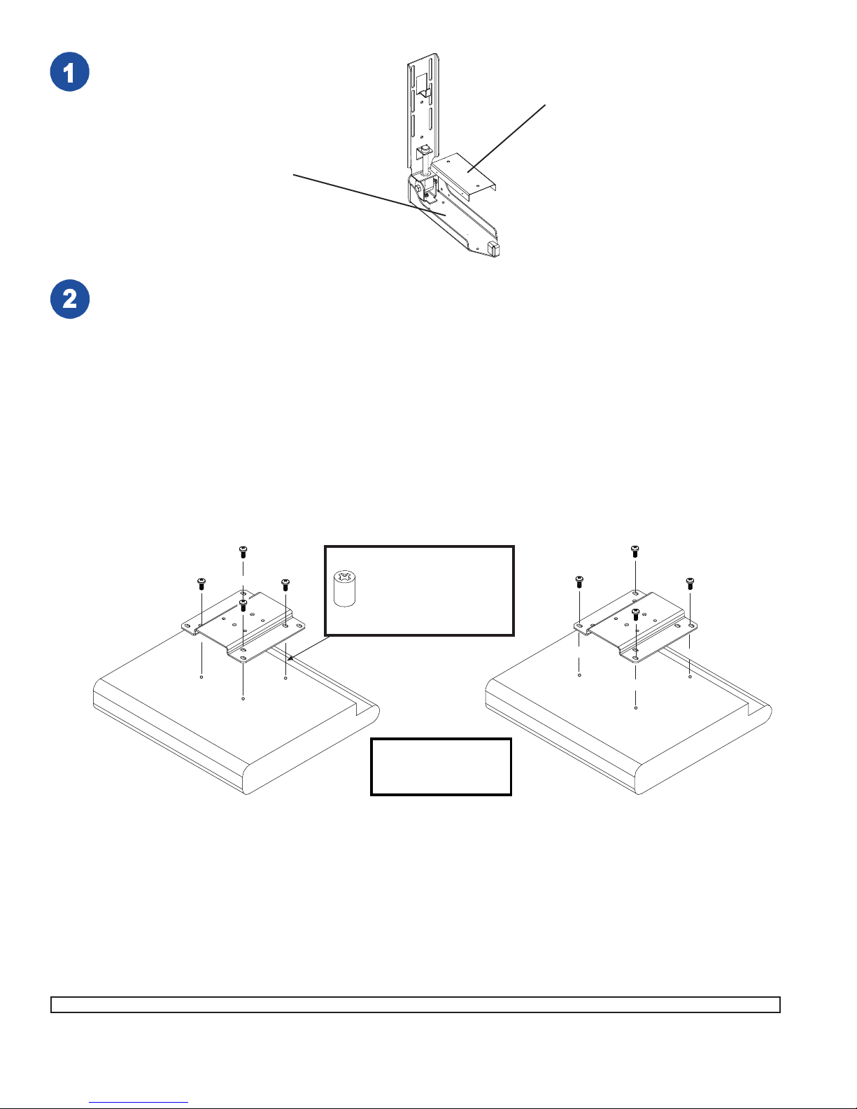
Remove cord cover from LCD assembly (A).
Cord Cover
A
This product is designed to accommodate screens with VESA® compliant hole
pattern. For safe mounting, please make sure that mounting screws turn at least
three complete turns in the screen inserts.
FOR VESA 75 MOUNTING PATTERN: 1.)
Choose hole pattern indicated below. 2.)
Attach adapter bracket (B) to back of monitor
using four M4 x 10 mm screws (C) as indicated below. 3.) If hole pattern is in a pocket,
attach adapter bracket (B) to back of monitor
using four M4 x 20 mm screws (O) and four
retaining spacers (N) as indicated below.
B
FOR VESA 100 MOUNTING PATTERN: 1.) Choose
hole pattern indicated below. 2.) Attach adapter
bracket (B) to back of monitor using four M4 x 10
mm screws (C) as indicated below. Note: If installing
LCD screen model Sharp® LC-13E1U, LC-15E1U,
LC-20E1U, or if you don't get three complete turns in
the screen inserts, use four M4 x 12 mm screws (M)
instead of four M4 x 10 mm screws (C).
For monitors with a hole
pattern in a pocket,
spacers (N) go between
adapter bracket (B) and
monitor.
B
Monitor may appear
slightly different than
illustrated
Visit the Peerless Web Site at www.peerlessindustries.com For customer service call 1-800-729-0307 or 708-865-8870.
2 of 4
ISSUED: 08-11-03 SHEET #: 090-9093-3 11-10-04
Page 3

Locate the bracket in the slot so that
the top of the TV does not touch the
round cover or go above it when the tilt
is in the open position as shown in
figure 1. Place 1/4 split washer (L) on
M5 screw (K) before #10 SAE washer
(I) and fasten adapter plate (B) to LCD
assembly (A) as shown in figure 2.
Round Cover
A
K
L
I
figure 1
B
Sample location: your
screen may mount in a
different location in the slot.
Carefully hold the closed mount with the TV against the
bottom of your cabinet. Make sure that there is enough
clearance between the back of the TV and the wall to
clear the back tab. Drill four 1/4” holes to match the
drawing to the right.
CAUTION
• We recommend taking the screen off the mount to
affix the bracket to the cabinet, to avoid any damages
to the screen.
Fasten LCD Assembly (A) to cabinet using four
10-32 x 1.25” screws (D) four #10 SAE washers (I) and four 1/4” spacers (E). Get all four
screws (D) started before tightening.
Back holes of
LCD assembly
I
Wall
figure 2
A
Back T ab
TOP VIEW
D
or
6.00”
1.25”
F
Note: If cabinet underside has lip, use four 7/8”
spacers (G) and four 10-32 x 2” screws (F)
instead of screws (D) and spacers (E). This
lowers LCD Assembly (A) by 7/8” to allow LCD
Assembly (A) to open and close without
obstruction.
EG
Visit the Peerless Web Site at www.peerlessindustries.com For customer service call 1-800-729-0307 or 708-865-8870.
or
3 of 4
ISSUED: 08-11-03 SHEET #: 090-9093-3 11-10-04
Page 4
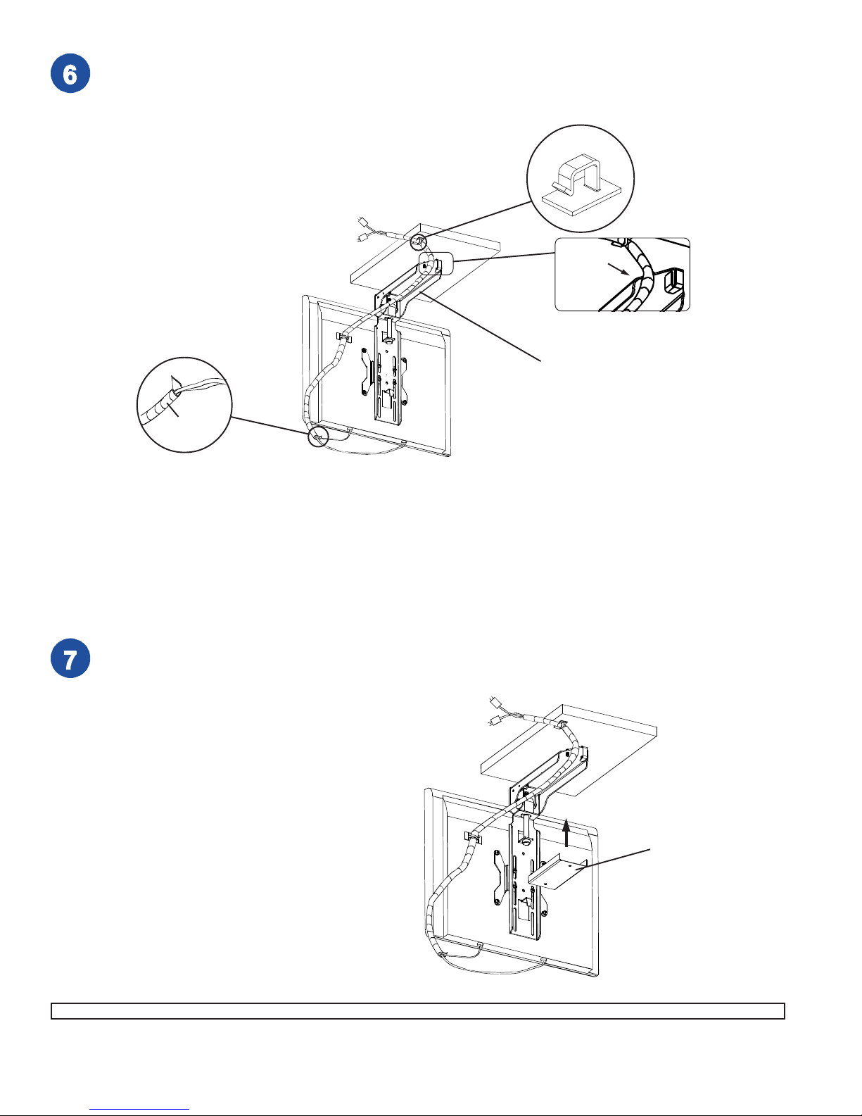
Reattach screen onto bracket using the same
position determined in step 4. Wind helical wrap (J)
around all cords from back of LCD TV , as shown.
Place cord clips (H) as needed, to better manage
cords, making sure that one clip is close enough to
the hinge area to prevent cord from bunching up.
Note: Make sure that cords come out right side of
LCD assembly (A).
J
H
Right Side
A
Place cord cover back onto LCD assembly (A), so that it
is even with the bends on the side of the mount.
Note: Make sure all slack is pulled out with mount fully
open before replacing cord cover.
Cord Cover
4 of 4
Visit the Peerless Web Site at www.peerlessindustries.com For customer service call 1-800-729-0307 or 708-865-8870.
© 2004 Peerless Industries, Inc. All rights reserved.
Peerless is a registered trademark of Peerless Industries, Inc.
All other brand and product names are trademarks or registered trademarks of their respective owners.
ISSUED: 08-11-03 SHEET #: 090-9093-3 11-10-04
 Loading...