

Page 1
User Guide
ULTRAVIEW™ UHD OUTDOOR TELEVISION
MODEL: UV492, UV552, UV652
ENG
1
2017-02-17 #:180-9099-4 (2019-03-28)
Page 2
SYSTEM INSTALLATION AND ELECTRICAL REQUIREMENTS
Electrical Code
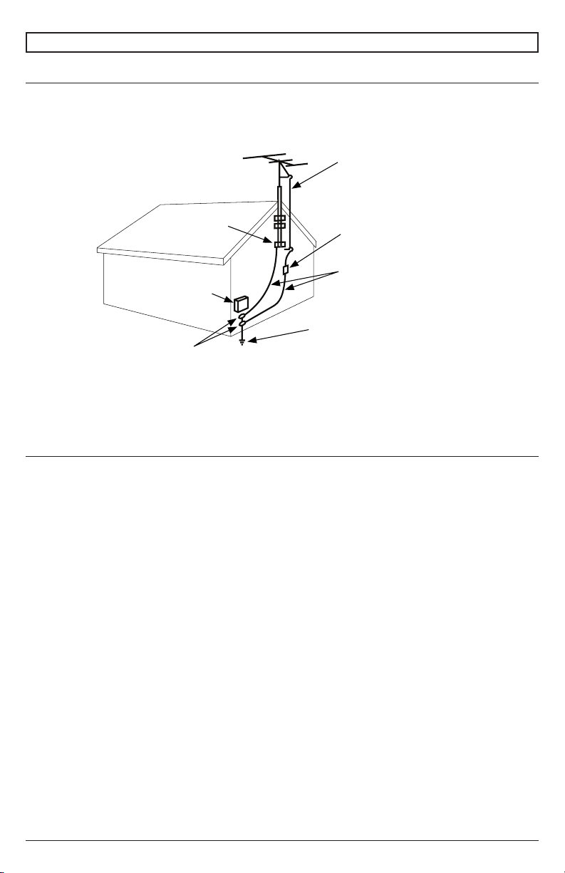
Note: To the display system installer: This reminder is provided to call attention to Article 820-44 of
the National Electric Code that provides guidelines for proper grounding and, in particular, species
that the cable ground shall be connected to the grounding system of the facility. Outlet shall be
installed near the equipment and shall be easily accessible.
Antenna lead-in wire
NEC National Electric Code
Ground clamp
Electric service
equipment
Ground clamps
Note: Installation shall incorporate UL Listed external surge protection rated 2500 Vpk or less, for 150
to 300 Vac mains, installed in accordance with Article 285 of ANSI/NFPA 70 or applicable local codes.
Antenna discharge unit
(NEC Section 810-20)
Grounding conductors
(NEC Section 810-21)
Power service grounding
electrode system
(NEC Art 250 Part H)
Power Source
The display must be connected to a mains socket outlet with a protective grounding connection.
The mains plug is used as the disconnect device and shall remain readily accessible.
Electrical installation shall be in accordance with the applicable parts of Chapter 8 of ANSI/NFPA70.
An outdoor antenna should not be located near overhead electrical lines or any electrical circuits.
If an outside antenna is connected to the receiver, conrm that the antenna system is grounded to
protect against voltage surges and built up static charges. Section 810 of the National Electric Code,
ANSI/NFPA No 70-1984, provides information with respect to proper grounding for the mast and
supporting structure, grounding of the lead-in wire to an antenna discharge unit, size of grounding
connectors, location of antenna discharge unit, connection to grounding electrodes and requirements
for the grounding electrode.
This display operates on 100-240 volts 50-60 Hz, AC current. Insert the power cord into a 120 volt
60 Hz outlet. Never connect the display to direct current or anything other than the specied voltage.
To prevent electric shock from the display, do not use with an extension cord, receptacle, or other
outlet unless the blades and ground terminal can be fully inserted to prevent blade exposure.
All secondary lines must be routed through grounded conduit and kept separate from AC line.
2
2017-02-17 #:180-9099-4 (2019-03-28)
Page 3

FCC CAUTION
To assure continued compliance and possible undesirable interference, ferrite cores may be used
when connecting this display to video equipment; maintain at least 400mm (15.75 inches) spacing to
other peripheral devices.
FCC STATEMENT
This equipment has been tested and found to comply with the limits for a Class B digital device,
pursuant to Part 15 of the FCC Rule. These limits are designed to provide reasonable protection
against harmful interference in a residential installation. This equipment generates, uses and can
radiate radio frequency energy and, if not installed and used in accordance with these instructions,
may cause harmful interference to radio communications; however, there is no guarantee that
interference will not occur in a particular installation. If this equipment does cause harmful
interference to radio or television reception, which can be determined by turning the equipment o
and on, the user is encouraged to try to correct the interference by one or more of the following
measures:
1. Reorient or relocate the receiving antenna.
2. Increase the separation between the equipment and receiver.
3. Connect the equipment into an outlet on a circuit dierent from that to which the receiver is
connected.
4. Consult the dealer or an experienced radio/display technician for help.
This device complies with Part 15 of the FCC Rules. Operation is subject to the following two
conditions:
• This device may not cause harmful interference.
• This device must accept any interference received, including interference that may cause
undesired operation.
Relevant Information
Record your display's model and serial number here for future reference. Keep this user manual in an
accessible location in the event service is required.
Note: Your display's serial number can be found on the box and underneath the rear cover plate.
Model Number ____________________________________
Serial Number ____________________________________
3
2017-02-17 #:180-9099-4 (2019-03-28)
Page 4
GENERAL SAFETY PRECAUTIONS
Read before operating equipment
Thank you for purchasing our product. Before using it, please read this user guide carefully and follow
the instructions for safe operation. Please keep this manual for future reference and always include it
when transferring or transporting this product to a dierent location.
WARNING
In case of emergency such as re or electric shock caused by the product, immediately contact 911
or proper emergency police/re service agencies in your country.
To reduce the risk of electric shock or re, heed the following:
• In case of product malfunction or unusual events such as electrical burning smell, smoke, or
loss of content signals due to internal overheating, immediately turn o, unplug the electrical
cord and contact the manufacturer.
• Do NOT disassemble, modify or service product in any way other than that contained in this
instruction. Any unauthorized modications made to the product automatically void product
warranty.
• Do NOT touch antenna lines or wires, electrical cables or plugs when lightning or thunder is
present or with wet hands
• Do NOT submerge in water.
• Do NOT destroy, process, or place close to any heat source.
• Do NOT install near poisonous gas or chemically unstable atmosphere.
• Do NOT install near strong magnetic or electrical current eld.
• Do NOT install the product in unstable locations or near moving objects, constantly vibrating
equipment, or uneven surfaces.
• Do NOT leave any re source, such as candles, close to or on the product.
• Do NOT operate the product if it has been dropped or struck. Severe physical impact to the
product may cause components to fall out of place within and break.
• Do NOT bend or twist electrical cords, electrical plugs, cables, or wires with excessive force.
• Do NOT block ventilation slots or place any heavy object on the product.
• Use properly rated electrical voltage.
• Do NOT use any electrical sockets or power strips with many other devices jointly plugged
in. Use a single, directly dedicated and rated GFCI electrical outlet for the product for safe
operation.
• Do NOT move or transport with any cables (electrical, content connectivity) plugged in to the
source devices.
• Always connect the electrical plug rmly and completely. When disconnecting any cables,
always pull on the plug and not the cord.
• Always leave the power o when plugging or unplugging the electrical cords or connection
cables.
• Do not defeat the safety purpose of the polarized or grounding type electrical plug. A polarized
plug has two blades with one wider than the other. A grounding type plug has two blades and
a third grounding prong. The wide blade or the third prong are provided for your safety. If the
provided plug does not t into your outlet, consult an electrician for replacement of the obsolete
outlet.
• Protect the electrical cord from being walked on or pinched particularly at plugs, convenience
receptacles, and the point where they exit from the apparatus.
4
2017-02-17 #:180-9099-4 (2019-03-28)
Page 5
WARNING
• Never apply pressure to the exterior of the LCD screen.
• If monitor or glass is broken, do not come in contact with the liquid crystal and handle with care.
• Do NOT climb on the product.
• Do NOT install within ve feet from a body of water.
• Do NOT use if ambient air temperature exceeds the operating limits.
• Do NOT install in enclosure or recessed cavity with less than 2 inches of airow around the
display. Air inside fully encased display must be ventilated.
• The product is to be secured to building before operation.
• Product must be carried and supported by at least two persons.
• Periodically clean dust o the electrical plug to keep it clean and dry, ensuring proper and safe
operation.
• Only use attachments/accessories specied by the manufacturer.
5
2017-02-17 #:180-9099-4 (2019-03-28)
Page 6

CONTENTS
System Installation And Electrical Requirements ..................................................................................2
Electrical Code ...............................................................................................................................2
Power Source ................................................................................................................................2
FCC Caution ...................................................................................................................................3
FCC Statement ...............................................................................................................................3
Relevant Information .....................................................................................................................3
General Safety Precautions ...................................................................................................................4
Set Up Instructions .................................................................................................................................7
Parts List ........................................................................................................................................7
Removing Cord Cover ....................................................................................................................8
Connecting Cords ..........................................................................................................................9
Installing IR Extender .....................................................................................................................9
Replacing Cord Cover .................................................................................................................10
Connecting To The Power Source ................................................................................................ 11
Prepare The Display For Mounting ..............................................................................................12
Remote Control Battery Installation And Replacement ................................................................14
Operating Instructions ..........................................................................................................................15
Power On/O the Display .............................................................................................................15
Onboard Controls .........................................................................................................................15
Navigating The On-Screen Menu ................................................................................................16
Channel ...............................................................................................................................16
Picture .................................................................................................................................16
Audio ...................................................................................................................................16
Time ....................................................................................................................................17
Setup ...................................................................................................................................17
Lock .....................................................................................................................................18
USB Functionality ........................................................................................................................19
(RS-232C) Serial Control Of The TV ...........................................................................................21
Maintenance ........................................................................................................................................22
Care Of Screen ...........................................................................................................................22
Mobile Telephone Caution ...........................................................................................................22
End Of Life Directives ..................................................................................................................22
Product Specications .........................................................................................................................23
Display ..........................................................................................................................................23
Power ..........................................................................................................................................23
TV Controller Features ................................................................................................................23
Environmental .............................................................................................................................23
Mechanical ..................................................................................................................................24
Input/Output Connections ............................................................................................................24
Warranty ..............................................................................................................................................25
6
2017-02-17 #:180-9099-4 (2019-03-28)
Page 7
SET UP INSTRUCTIONS
AUX
LAST
OK
INFO
+
EXIT
CBLDVD
MUTE
POWER
VCR SAT
SOURCE
TV
1
4
7
.
2
5
8
0
3
6
9
VOL
REW PLAY FF MENU
REC STOP PAUSE GUIDE
CH
AUX
LAST
OK
INFO
+
EXIT
CBLDVD
MUTE
POWER
VCR SAT
SOURCE
TV
1
4
7
.
2
5
8
0
3
6
9
VOL
REW PLAY FF MENU
REC STOP PAUSE GUIDE
CH
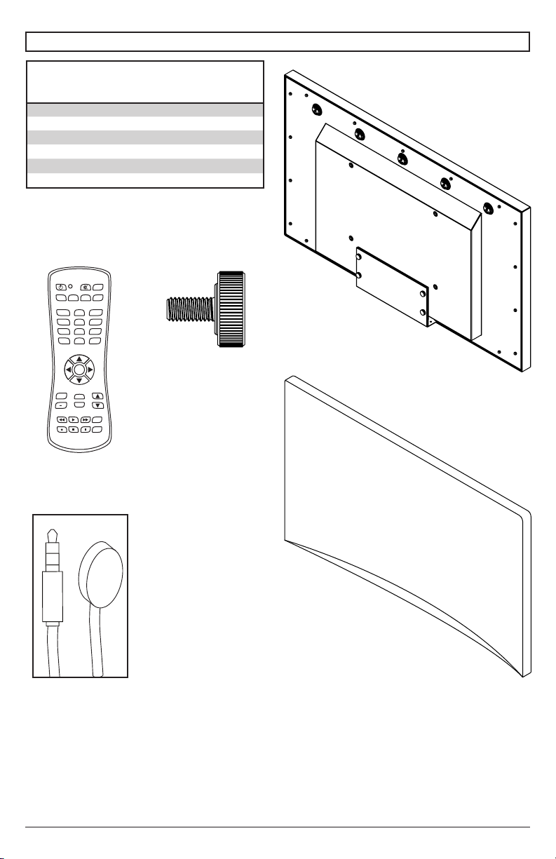
Parts List
Description Qty
A television 1
B display dust cover 1
C remote 1
D thumb screw (preinstalled) 4
E IR extender 1
F user guide (not shown) 1
(1)
A
television
(1)
C
remote
POWER
SOURCE
MUTE
AUX
CBLDVD
TV
VCR SAT
1
2
3
4
5
6
7
8
9
.
LAST
0
OK
VOL
CH
+
INFO
EXIT
REW PLAY FF MENU
REC STOP PAUSE GUIDE
(1)
E
IR extender
IR
IN
(4)
D
thumb screw
(1)
B
display dust
cover
7
2017-02-17 #:180-9099-4 (2019-03-28)
Page 8
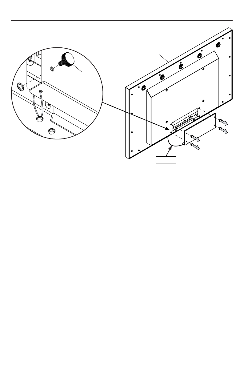
Removing Cord Cover
Remove (4) thumb screws (D) and cord cover plate to access source connection panel. Do not
disconnect lanyard.
A
D (4)
lanyard
8
2017-02-17 #:180-9099-4 (2019-03-28)
Page 9
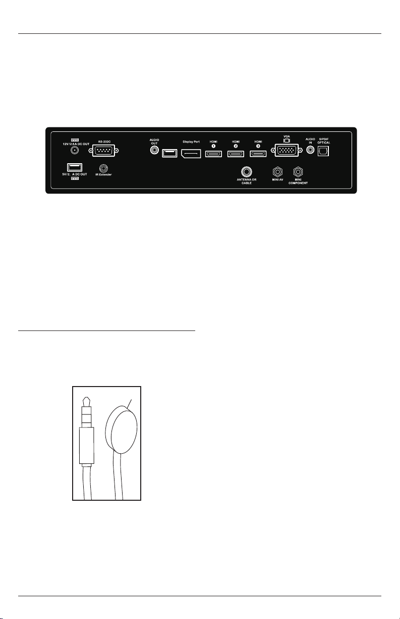
Connecting Cords
Connect source devices to appropriate display input. Make all connections prior to powering on the
display. The USB 2.0 Data port is for service and media only. For 5VDC power, use the 5VDC power
port.
12VDC 2.5A
RS-232C
4
USB 2.0 Data
Audio Out
USB 2.0
Data
HDMI 1 (ARC)
DisplayPort
HDMI 3 (MHL)
HDMI 2
VGA
S/PDIF Optical
Audio In
USB 5VDC 2.4A
IR Extender
Installing IR Extender (Optional)
Insert the 3.5mm end of the included 5V
IR extender into the IR Extender port on
the input panel of the display. IR extender
port may not be compatible with other 3rd
party extenders.
E
IR
IN
Mini Component
Mini AV
Antenna or Cable
9
2017-02-17 #:180-9099-4 (2019-03-28)
Page 10
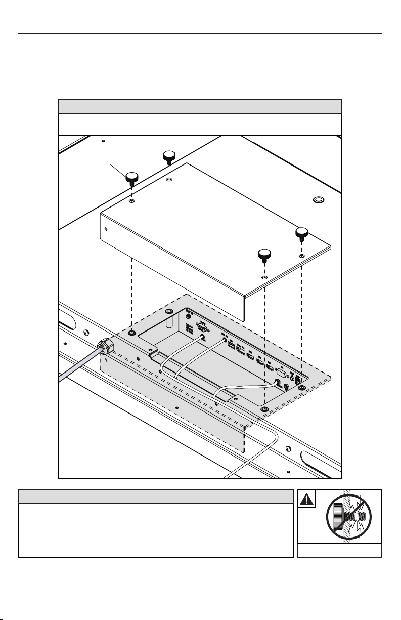
Replacing Cord Cover
1. Run cables across foam gasket block. Leave approximately 1/2" (13mm) between cables to
ensure a proper seal.
2. Replace cord cover plate and (4) thumb screws (D). Fasten thumb screws until gasket on cord
cover plate is fully compressed to back of television. Cables will seal between TV's gasket and
cord cover's gasket as cover is pressed into place. Route cables through opening at end of cord
cover.
CAUTION
Failure to follow these instructions can result in the product being damaged,
destroyed, and voiding the warranty.
D (4)
CAUTION
• Ensure cord bend radius does not exceed limits set by the
manufacturer.
• Ensure cords are seated properly in the cable channels to avoid
potential damage to cords when rear cover plate is installed.
• Do not remove lanyard that connects the rear cover plate to the display.
10
2017-02-17 #:180-9099-4 (2019-03-28)
Do not overtighten screws
Page 11
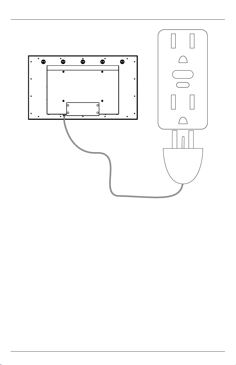
Connect To The Power Source
Connect power cord to GFCI outlet.
11
2017-02-17 #:180-9099-4 (2019-03-28)
Page 12
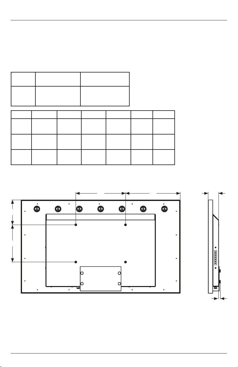
Prepare The Display For Mounting
Install cords prior to mounting your display. Input panel may be obstructed once the display is
mounted.
A mounting solution is sold separately. Contact your Peerless-AV representative for an outdoor rated
mounting solution for your particular application.
For your safety, only install an outdoor-rated mount that is suitable for the application and supports
the weight of the display. When mounting a display outdoors, use proper environmentally rated
mounts to ensure longevity in harsh environments.
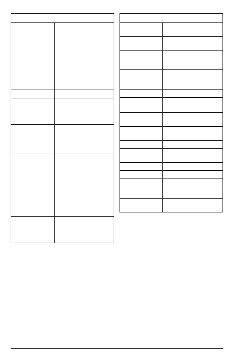
Examine the chart below to determine the mounting specications for your display:
Model
UV492
UV552
UV652
Model A B C D E F
UV492
UV552
UV652
Mounting Hole
Pattern
400x200mm
400x300mm
400x400mm
15.75"
(400mm)
15.75"
(400mm)
15.75"
(400mm)
7.87"
(200mm)
11.81"
(300mm)
15.75"
(400mm)
Required Mounting
Screws
(4) M8 screws
(17.4mm long)
14.69"
(373mm)
17.37"
(441mm)
21.69"
(551mm)
8.38"
(213mm)
7.93"
(201mm)
8.39"
(213mm)
3.34"
(85mm)
3.34"
(85mm)
3.39"
(86mm)
.61"
(16mm)
.61"
(16mm)
.61"
(16mm)
A
D
B
REAR VIEW SIDE VIEW
12
C E
F
2017-02-17 #:180-9099-4 (2019-03-28)
Page 13
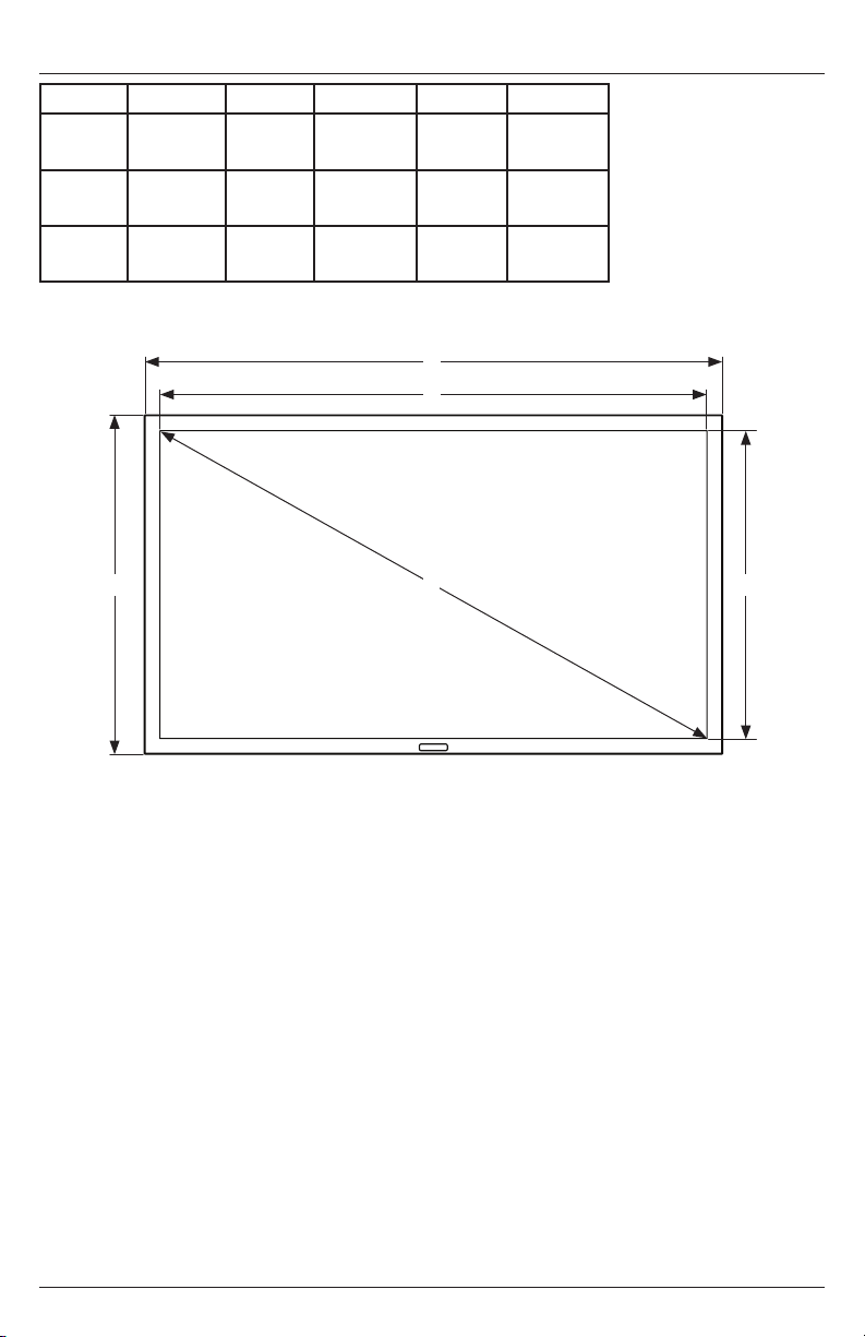
Prepare The Display For Mounting
Model A B C D E
UV492
UV552
UV652
45.13"
(1146mm)
50.50"
(1283mm)
59.00"
(1501mm)
26.64"
(677mm)
29.66"
(753mm)
34.53"
(877mm)
42.3"
(1074mm)
47.66"
(1211mm)
56.28"
(1429mm)
23.8"
(605mm)
26.833"
(681mm)
31.68"
(805mm)
A
C
48.28"
(1226mm)
54.62"
(1387mm)
64.19"
(1630mm)
B D
E
FRONT VIEW
13
2017-02-17 #:180-9099-4 (2019-03-28)
Page 14
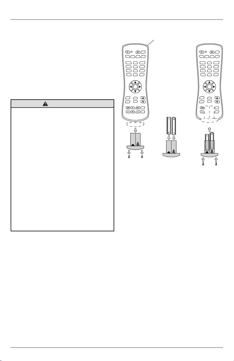
Remote Control Battery Installation And Replacement
AUX
LAST
OK
INFO
+
EXIT
CBLDVD
MUTE
POWER
VCR SAT
SOURCE
TV
1
4
7
.
2
5
8
0
3
6
9
VOL
REW PLAY FF MENU
REC STOP PAUSE GUIDE
CH
AUX
LAST
OK
INFO
+
EXIT
CBLDVD
MUTE
POWER
VCR SAT
SOURCE
TV
1
4
7
.
2
5
8
0
3
6
9
VOL
REW PLAY FF MENU
REC STOP PAUSE GUIDE
CH
The remote control is powered by two 1.5V AAA
batteries installed at the factory.
To install or replace batteries:
1. To remove the battery module of the remote
control, remove the two screws on the end of
the battery module. Slide the battery module
out of the remote control.
2. Insert two new “AAA” size batteries into the
battery module.
3. Slide the battery module back into the remote
control and reinsert the two screws in the end
of the battery module.
CAUTION
Incorrect usage of batteries can result in leaks
or bursting. Peerless-AV recommends the
following battery use:
• Do not mix battery brands.
• Do not combine new and old batteries. This
can shorten the battery life or cause battery
acid leaks.
• Remove dead batteries immediately to
prevent battery acid from leaking into the
battery compartment.
• Do not touch exposed battery acid as it
may injure skin.
• Remove the batteries if you do not intend
to use the remote control for a long period
of time.
• Do not expose the batteries to excessive
heat from sunlight, re or other heat
sources or batteries could explode.
• Fully tighten screws to maintain the ingress
protection rating of the remote.
POWER
TV
VCR SAT
1
2
4
5
7
8
.
0
OK
VOL
+
INFO
EXIT
REW PLAY FF MENU
REC STOP PAUSE GUIDE
C
SOURCE
MUTE
AUX
CBLDVD
3
6
9
LAST
CH
POWER
TV
VCR SAT
1
2
4
5
7
8
.
0
OK
VOL
+
INFO
EXIT
REW PLAY FF MENU
REC STOP PAUSE GUIDE
SOURCE
MUTE
AUX
CBLDVD
3
6
9
LAST
CH
14
2017-02-17 #:180-9099-4 (2019-03-28)
Page 15
OPERATING INSTRUCTIONS
Power On/O The Display
Power on your TV by using the remote control or the rear power button on the side of the TV. The TV
will power on but image may not appear for several seconds as it completes its power up sequence.
Point the remote control at the IR sensor located
behind the Peerless-AV logo at the center of the
TV and press the power button
POWER
TV
MUTE
SOURCE
VCR SAT
1
CBLDVD
4
AUX
2
7
5
3
.
8
6
0
9
LAST
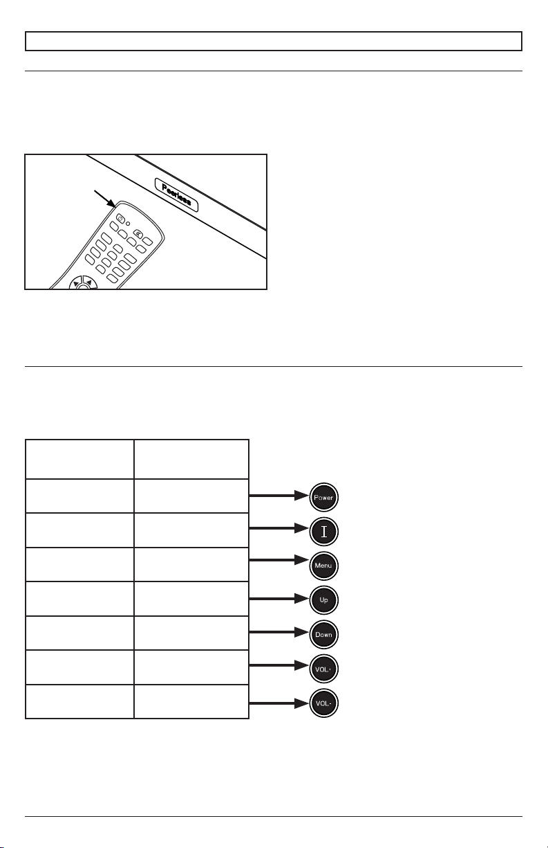
Onboard Controls
Direct Mode: Allows for quick access to source selection, volume settings and channel selection.
Menu Mode: Press the Menu button to access Menu Mode and activate the On Screen Display
(OSD). For a description of OSD operation refer to the next section.
The keypad buttons are assigned as indicated in the table below.
Menu Mode Direct Mode
On/O On/O
OK Input Select
Menu Menu
Up Channel Up
Down Channel Down
Right Volume Up
Left Volume Down
15
2017-02-17 #:180-9099-4 (2019-03-28)
Page 16
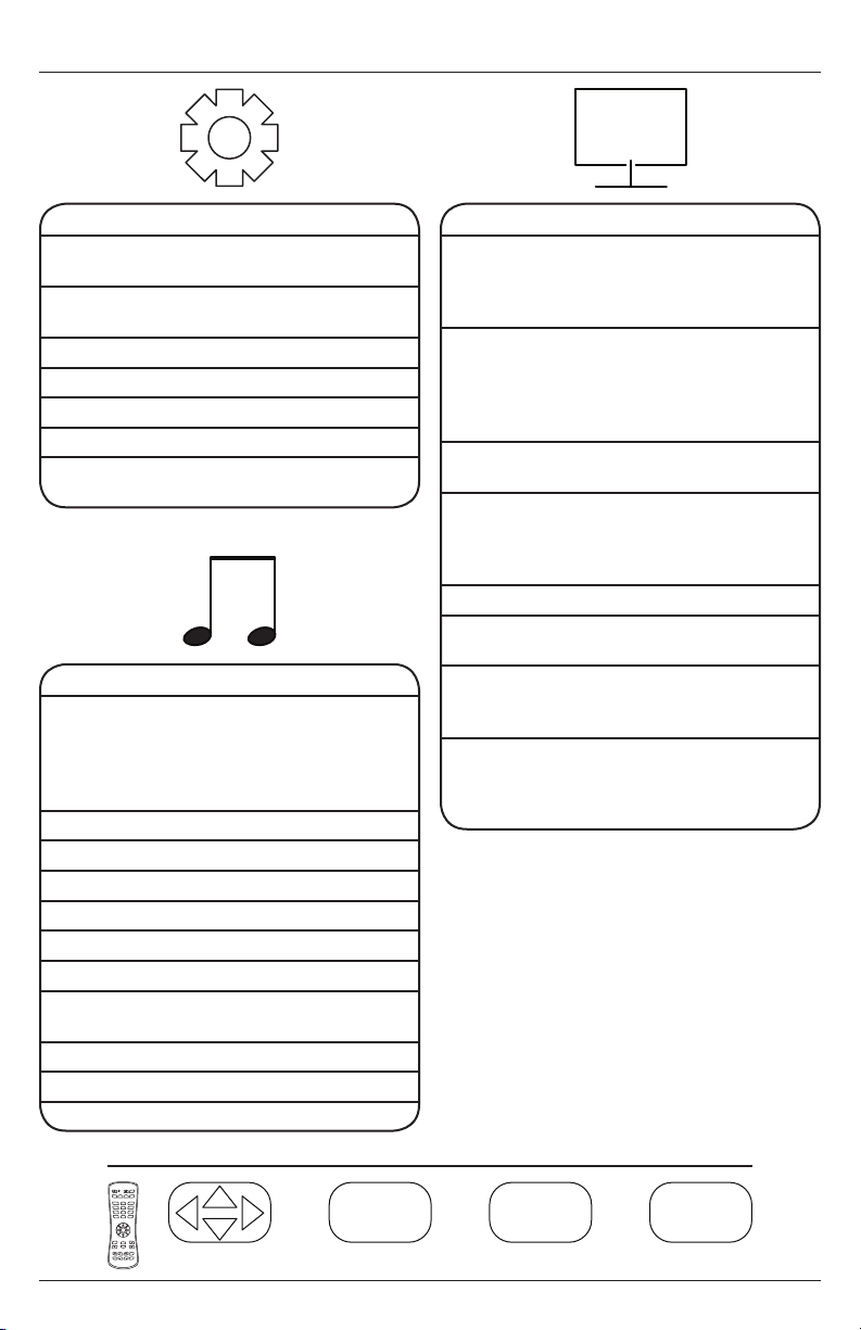
Navigating The On Screen Menu
MENUEXIT
OK EXIT
Channel
Air / Cable Choose between antenna
Auto Scan Searches for available
Favorite Shows favorite channels
Show/Hide Show or hide channels
Channel No. Displays list of channels
Channel Label Change channel names
DTV Signal Displays channel info and
and cable
channels
signal strength
Audio
Equalizer Standard
120 Hz 50
500 Hz 50
1.5 kHz 50
10 kHz 50
Balance 50
Digital Output
(Optical)
Surround On / O
Audio Only On / O
Music
Movie
Sports
Personal
5 kHz 50
PCM / Raw / O
AVC On / O
Picture
Picture Mode Theater
Color Temp. Normal
HDMI Mode Video Mode
Zoom Mode 4:3
Backlight 0 - 100
DLC (Dynamic
Backlight)
Color Range Auto
Personal
Standard
Dynamic
Warm
Cool
Personal
Point to Point
PC Mode
16:9
Cinema
Zoom
On / O
0 - 255
16 - 234
3DNR O
Weak
Middle
Strong
POWER
MUTE
SOURCE
AUX
CBLDVD
TV
VCR SAT
1
2
3
4
5
6
7
8
9
.
LAST
0
OK
CH
VOL
+
INFO
EXIT
REW PLAY FF MENU
REC STOP PAUSE GUIDE
Navigate Enter Exit Return
OK
16
EXIT
MENU
2017-02-17 #:180-9099-4 (2019-03-28)
Page 17
MENUEXIT
OK EXIT
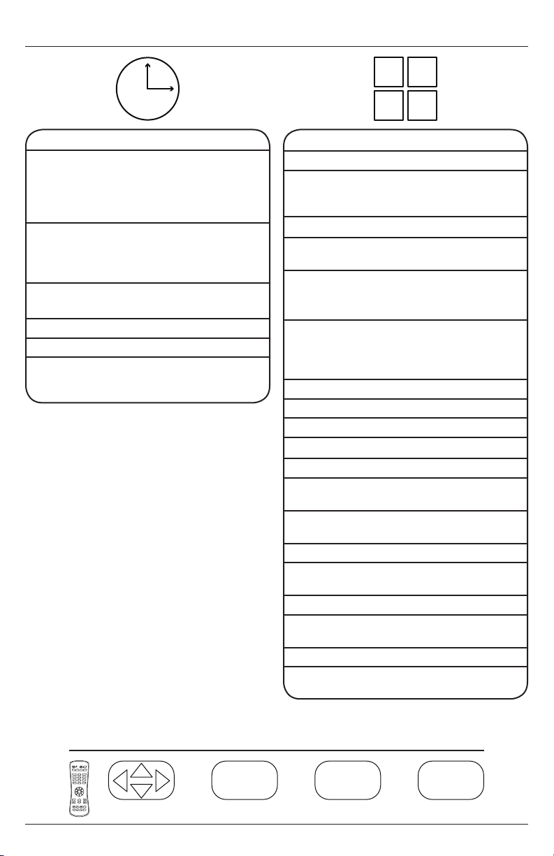
Navigating The On Screen Menu
Time
Sleep Timer o
5 min
10 min
15 min
30 min
Time Zone Atlantic
Eastern
Central
Mountain
Time Format 12-hour
24-hour
Auto Sync On / O
Clock Enter Current Time
Wake Up Enter desired time when
display will turn on
*One time event
60 min
90 min
120 min
180 min
240 min
Pacic
Alaska
Hawaii
Korean
Setup
Menu Languages
Transparent
(Menu
Transparency)
English / Spanish / French
0%
25%
75%
100%
50%
Closed Caption
CC Mode CC O / CC On /
Analog CC CC1 / CC2 /CC3 / CC4 /
Digital CC
Restore Defaults Factory reset all options
Setup Wizard
Software Update Yes / No
CC On Mute
Text 1 / Text 2 / Text 3 /
Text 4
O /
Service 1 /
Service 2 /
Service 4 /
Service 5 /
Service 6
Service 3 /
CEC
CEC Control On / O
Device Auto
Power O
TV Auto
Power On
Audio Receiver On / O
Device Lists Lists connected CEC
Connect (future use)
Root Menu Menu of connected
EDID Switch 1.4, 2.0
No Signal Auto
Power O
On / O
On / O
devices
souce device
On / O / Backlight
POWER
MUTE
SOURCE
AUX
CBLDVD
TV
VCR SAT
1
2
3
4
5
6
7
8
9
.
LAST
0
OK
CH
VOL
+
INFO
EXIT
REW PLAY FF MENU
REC STOP PAUSE GUIDE
Navigate Enter Exit Return
OK
17
EXIT
MENU
2017-02-17 #:180-9099-4 (2019-03-28)
Page 18
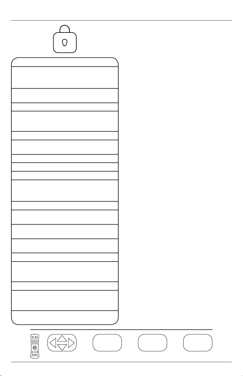
Navigating The On Screen Menu
MENUEXIT
OK EXIT
Lock
System Lock
Enter Password to enter System Lock settings
Enter password to enter hotel mode settings
Defaut Password: 0000
Change
password
Allows the password to be
changed
System Lock On / O
Input Block TV, AV, Component, DP,
HDMI 1, HDMI 2, HDMI 3,
PC, USB
US TV, MPAA
Canada Canadian English,
Canadian French
RRT Setting
Reset RRT
Unrated On /O
Hotel Mode
Defaut Password: 0000
Hotel Mode On / O
Change
Password
Allows the password to be
changed
Picture Mode Standard, Dynamic,
Theater, Personal
Sound Mode Standard, Music, Movie,
Sports, Personal
Key Lock On / O
Power On
Source
TV, AV, Component, DP,
HDMI 1, HDMI 2, HDMI 3,
PC, USB
Air / Cable Air, Cable
Power On
Channel
Set channel that display
will tune to when powered
on
Power On
Volume
Set volume that display
will output when turned on
POWER
MUTE
SOURCE
AUX
CBLDVD
TV
VCR SAT
1
2
3
4
5
6
7
8
9
.
LAST
0
OK
CH
VOL
+
INFO
EXIT
REW PLAY FF MENU
REC STOP PAUSE GUIDE
Navigate Enter Exit Return
OK
18
EXIT
MENU
2017-02-17 #:180-9099-4 (2019-03-28)
Page 19
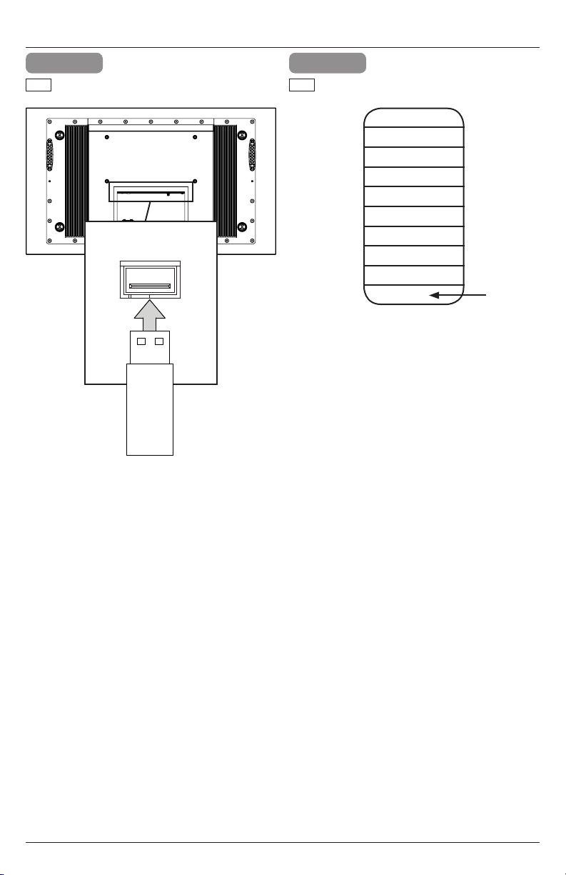
USB Functionality
1 2
ENG
Insert USB ash drive into USB 2.0 Data
port on the input panel of the display.
USB 2.0
Data
ENG
Select USB source to access content.
Input Source
TV
AV
Component
DP
HDMI1
HDMI2
HDMI3
PC
USB
19
2017-02-17 #:180-9099-4 (2019-03-28)
Page 20
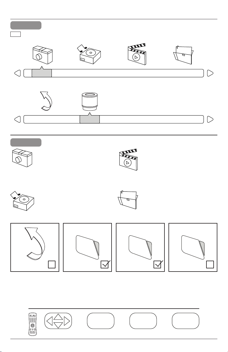
USB Functionality
PHOTO
MUSIC MOVIE TEXT
MENUEXIT
OK EXIT
3
ENG
Select media type and folder where content is stored.
PHOTO
Return C
4
Photos – To view a single photo,
select photo and press play. To view
a slide show, select multiple photos
and press play. Use on screen
menu to control slide show.
Music – To listen to a single song,
select song and press play. To listen
to a playlist, select multiple songs
and press play. Use on screen
menu to control playlist.
MUSIC MOVIE TEXT
Movies – To view a single video,
select video and press play. To view
a playlist, select multiple videos and
press play. Use on screen menu to
control playlist.
Text – To view to a single text le,
select le and press play. To view
a playlist, select multiple les and
press play. Use on screen menu to
control playlist.
POWER
TV
1
4
7
.
VOL
+
REW PLAY FF MENU
REC STOP PAUSE GUIDE
MUTE
SOURCE
AUX
CBLDVD
VCR SAT
2
3
5
6
8
9
LAST
0
OK
CH
INFO
EXIT
OK
EXIT
Navigate Enter Exit Return
20
2017-02-17 #:180-9099-4 (2019-03-28)
MENU
Page 21
(RS-232C) Serial Control Of The Display
Attach an RS-232C cable (straight through type) to the supplied D-Sub RS-232C to utilize serial
control function. Control via RS232 should only be utilized by experts familiar with RS232 programing.
Menu:
Right:
OK:
Down:
Up:
Left:
Source:
(1):
(2):
(3):
(4):
(5):
(6):
(7):
(8):
(9):
(0):
Exit:
Power On:
Power O:
Power On/O:
Volume +:
Volume -:
Channel +:
Channel -:
Surround:
CC:
EPG:
Info:
MTS:
A0, F0, 55, FF, 4E, B1
A0, F0, 55, FF, 05, FA
A0, F0, 55, FF, 02, FD
A0, F0, 55, FF, 0D, F2
A0, F0, 55, FF, 17, E8
A0, F0, 55, FF, 0C, F3
A0, F0, 55, FF, 01, FE
A0, F0, 55, FF, 42, BD
A0, F0, 55, FF, 43, BC
A0, F0, 55, FF, 0F, F0
A0, F0, 55, FF, 1E, E1
A0, F0, 55, FF, 1D, E2
A0, F0, 55, FF, 1C, E3
A0, F0, 55, FF, 18, E7
A0, F0, 55, FF, 45, BA
A0, F0, 55, FF, 4C, B3
A0, F0, 55, FF, 56, A9
A0, F0, 55, FF, 1B, E4
A0, F0, 55, FF, AE, 51
A0, F0, 55, FF, AD, 52
A0, F0, 55, FF, 0B, F4
A0, F0, 55, FF, 0A, F5
A0, F0, 55, FF, 40, BF
A0, F0, 55, FF, 55, AA
A0, F0, 55, FF, 5A, A5
A0, F0, 55, FF, C7, 38
A0, F0, 55, FF, 44, BB
A0, F0, 55, FF, 49, B6
A0, F0, 55, FF, 50, AF
A0, F0, 55, FF, 11, EE
Mute:
Sleep:
AV:
VGA:
HDMI Toggle:
HDMI1:
HDMI2:
HDMI3:
DisplayPort:
TV:
DTV:
Component:
USB:
PMODE:
Zoom:
SMODE:
VOL 0%:
VOL 25%:
VOL 50%:
VOL 75%:
VOL 100%:
Brightness 0%:
Brightness 25%:
Brightness 50%:
Brightness 75%:
Brightness 100%:
Dash:
Channel Fav List:
Channel List:
Channel Return:
A0, F0, 55, FF, 14, EB
A0, F0, 55, FF, 53, AC
A0, F0, 55, FF, ED, 12
A0, F0, 55, FF, EA, 15
A0, F0, 55, FF, EC, 13
A0, F0, 55, FF, DE, 21
A0, F0, 55, FF, DF, 20
A0, F0, 55, FF, E0, 1F
A0, F0, 55, FF, E4, 1B
A0, F0, 55, FF, E8, 17
A0, F0, 55, FF, E9, 16
A0, F0, 55, FF, E7, 18
A0, F0, 55, FF, 57, A8
A0, F0, 55, FF, 4B, B4
A0, F0, 55, FF, 51, AE
A0, F0, 55, FF, 5B, A4
A0, F0, 55, FF, 20, DF
A0, F0, 55, FF, 21, DE
A0, F0, 55, FF, 22, DD
A0, F0, 55, FF, 23, DC
A0, F0, 55, FF, 24, DB
A0, F0, 55, FF, 25, DA
A0, F0, 55, FF, 26, D9
A0, F0, 55, FF, 27, D8
A0, F0, 55, FF, 28, D7
A0, F0, 55, FF, 29, D6
A0,F0, 55, FF, 2E, D1
A0, F0, 55, FF, 1A, E5
A0, F0, 55, FF, 59, A6
A0, F0, 55, FF, 15, EA
COM Settings
Baud Rate 38400
Data Bits 8
Parity None
Stop Bits 1
21
2017-02-17 #:180-9099-4 (2019-03-28)
Page 22

MAINTENANCE
Care Of The Screen
Do not rub or strike the screen with anything hard as this may scratch, mark, or even damage the
screen permanently. Ensure that the TV is installed in a location where it will be safe from abrasives
and ying debris, which could damage the LCD panel. Never use ammonia or any product containing
ammonia, as it will damage the anti-glare coating on the face of the display. Only use an approved
screen cleaner to clean the display face. Dust the display by wiping the screen and the cabinet with
a soft, clean cloth. If the screen requires additional cleaning, use a clean, damp cloth. Do not use
aerosol cleaners or solvents of any kind. Do not use any chemical such as paint thinner or benzene
to clean the product’s exterior. It may cause scratches on the surface, erasing proper indications,
identication labels, or instructions on the exterior, which may cause misuse and improper operation
of the product. To prolong the life of the TV, install the dust cover when the TV is not is use.
Mobile Telephone Caution
Keep your mobile telephone away from your display to avoid disturbances in the picture or sound,
possibly causing permanent damage to your display.
End Of Life Directives
In an eort to produce environmentally friendly products, your new display contains materials that can
be recycled and reused. At the end of your display's life, specialized companies can minimize display
waste by separating reusable materials from non-reusable materials. Please ensure you dispose of
your display according to local regulations.
22
2017-02-17 #:180-9099-4 (2019-03-28)
Page 23
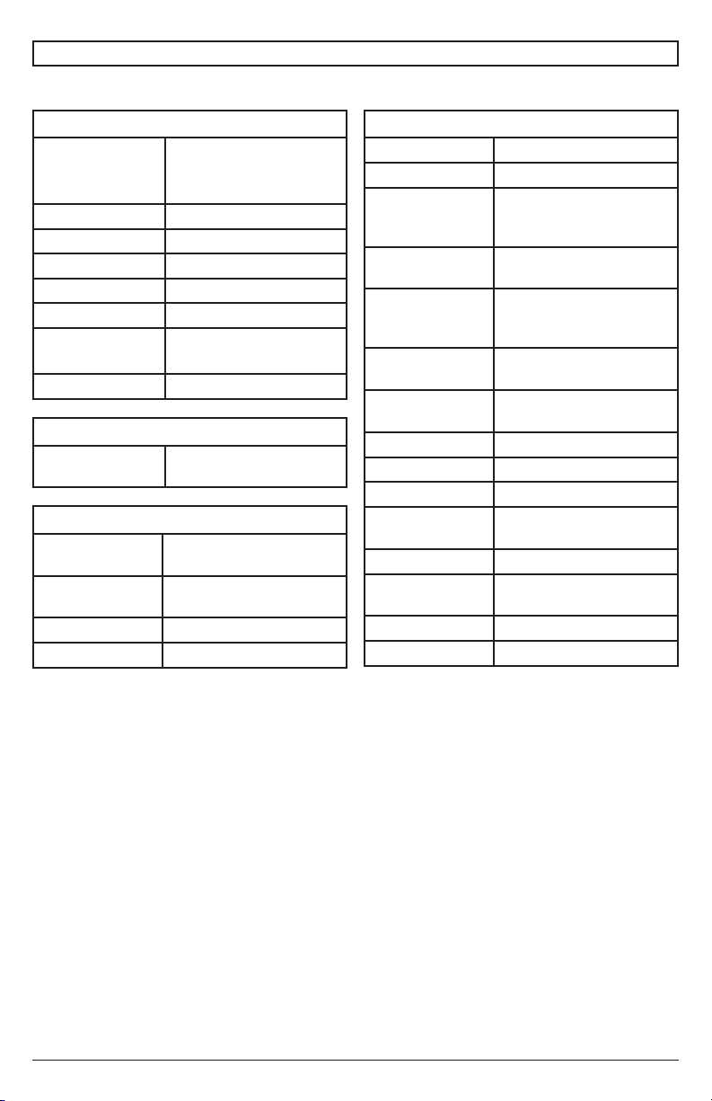
PRODUCT SPECIFICATIONS
Specications subject to change without notice
Display
Screen Size
(diagonal)
Aspect Ratio 16:9
Resolution 3840 x 2160
Brightness 500 cd/m
Contrast Ratio 1100:1
Viewing Angle 178° vertical / horizontal
Response Time
(gray to gray)
Refresh Rate 60 Hz
UV492: 49"
UV552: 55"
UV652: 65"
2
8ms
Power
AC Input 100 VAC to 240 VAC,
50 to 60 Hz
Environmental
Operating
Temperature
Storage
Temperature
IP Rating IP55
Safety/EMC FCC Class B
-22° F to 122° F
(-30° C to 50° C)
-4° F to 140° F
(-20° C to 60° C)
TV Controller Features
Analog TV NTSC
Digital TV ATSC / QAM 256
Picture
Adjustment
Picture Mode Standard, Dynamic,
Temperature
Adjustment
Screen
Adjustment
Clock, Sleep
V-chip Ye s
Closed Caption Yes
Electronic
Program Guide
Noise Reduction Yes
3-D Comb Filter
and De-interlace
OSD Language English, French, Spanish
Brightness / Contrast /
Tint / Sharpness / Noise
Reduction / Color
Theater, Personal
Color
Cool, Normal, Warm,
Personal
16:9 / Full / Zoom / 4:3 /
Point to Point
Yes
Timer
MTS Yes
Yes
Yes
Mute Yes
23
2017-02-17 #:180-9099-4 (2019-03-28)
Page 24
Mechanical
Display Size:
UV492
UV552
UV652
Enclosure Color Black
VESA Mount
UV492
UV552
UV652
Net Weight
UV492
UV552
UV652
Shipping Size
UV492
UV552
UV652
Shipping Weight
UV492
UV552
UV652
(W x H x D)
45.13" x 26.64" x 3.95"
(1146mm x 677mm x
100mm)
50.5" x 29.66" x 3.95"
(1283mm x 753mm x
100mm)
59.11" x 34.51" x 4.00"
(1501mm x 877mm x
102mm)
400x200mm
400x300mm
400x400mm
52.80 lbs (23.95kg)
61.18 lbs (27.75kg)
85.05 lbs (38.58kg)
(W x H x D)
48.94" x 30.75" x 8.35"
(1243mm x 781mm x
212mm)
55.31" x 34.33" 8.35"
(1405mm x 872mm x
212mm)
63.98" 39.06" 8.35"
(1625mm x 992mm x
212mm)
62.85 lbs (28.51kg)
73.12 lbs (33.17kg)
102.22 lbs (46.37kg)
Input/Output Connections
TV Input Coax (x1), 75 ohm, NTSC,
VGA Input 15 pin D-SUB (x1), Up to
HDMI Input HDMI (x3), 480i, 480p,
DisplayPort DisplayPort (x1), 480i,
CVBS Input 3.5mm (x1), 480i, 576i
YPbPr Input 3.5mm (x1), 480i, 480p,
VGA Stereo
Audio Input
Audio Output 3.5mm Stereo Headphone
RS232 Control 9 pin D-SUB (Female) (x1)
TosLink Digital
Audio Output
IR Extender 3.5mm (x1)
USB 2.0 Data USB A (Female) (x1)
5VDC 2.4A
Output
(USB Power)
12VDC 2.5A
Output
ATSC, 64 QAM, QAM 256
1920x1080@60HZ
576i, 576p, 720p, 1080i,
1080p, 2160p
480p, 576i, 576p, 1080i,
1080p, 2160p
720p, 1080i
3.5mm Analog Audio (x1)
(x1)
Optical (x1)
USB A (Female) (x1)
Barrel 2.5mm (ID)
5.5mm (OD) (x1)
24
2017-02-17 #:180-9099-4 (2019-03-28)
Page 25

LIMITED TWO-YEAR WARRANTY
TWO-YEAR PARTS & LABOR LIMITED WARRANTY
Terms of Peerless-AV®
The Peerless-AV Outdoor TV/Display is warrantied to be free of
defects in material and workmanship from the time of purchase by
the original owner. If this product is proven to be defective under
the terms and conditions of this warranty, Peerless-AV will repair or
replace defective parts with new and/or reconditioned parts at no
charge for the parts and labor to the original owner, subject to the
terms and conditions of this Limited Warranty. This Limited Warranty
covers failures due to defects in material or workmanship that occur
during normal use as follows:
• Parts – the warranty period for parts is: two (2) years from
the date of original purchase. During the applicable Limited
Warranty period for parts, defective parts will be replaced at
no charge. Parts used for the repair will be warrantied for the
remainder of the original warranty period for those parts.
• Labor – the warranty period for labor is: two (2) years from
the date of original purchase. During the applicable Limited
Warranty period for labor, Peerless-AV will provide the labor
for warranty repair at no charge for a period of two (2) years
from the date of original purchase.
• Original owner must provide verication of the date of
purchase when requesting Limited Warranty Services. A copy
of the original Dated Sales Receipt is required together with
the product serial number to obtain service under this Limited
Warranty.
• All repairs must be performed by a Peerless-AV Authorized
Service Provider.
• Customer is responsible for returning (including any freight
and shipping cost) defective unit to Peerless-AV Authorized
Service Provider. If the product is found to have no defects,
the customer will be responsible for return shipping costs
as well the diagnostic bench fee. If the product is found to
be covered by the manufacturer’s warranty, Peerless will
assume responsibility for return freight charges.
THIS LIMITED WARRANTY DOES NOT COVER:
• Labor to uninstall and reinstall the display / TV.
• Shipping damage.
• Damage caused during customer unpacking, and/or removal
of protective packing materials.
• Damage due to improper, incorrect or insucient AC voltage,
power surges or lightning strikes.
• Damage due to inadequate signal pickup, incorporation into
other products or repairs by anyone other than a Peerless-AV
Technician.
• Damage due to tampering or removal of any gasket material,
including but not limited to the cable gland gaskets within the
cable entry way.
• Damage which results from re, ood, lightning, tornado,
hurricane, large hail, extremely gusty winds, sand storms,
vandalism, terrorism or other acts of nature.
• Any unit which has been modied or damaged due to
improper installation or failure to obey the operating
instructions provided in the User Manual.
• Any failure, loss, damage or personal injury due to accident,
neglect, misuse, abuse, improper operation, improper
storage, alteration to the unit, or failure by the consumer to
follow operating instructions provided in the User Manual.
• Any owner other than the original owner.
• Any unit purchased from an unauthorized seller.
• If the original product serial number has been removed,
defaced or tampered with in any way.
• Any packaging or transportation charges incurred in
connection with warranty services.
• Indirect, consequential, or special damages except as
required by federal or state laws.
• Any unit tampered with, modied, adjusted, or repaired by
any party other than the Peerless-AV Authorized Service
Provider.
• Any cosmetic damages to the surface or exterior that has
been defaced or faded, or caused by normal wear and tear
or exposure to chemicals, acid rain, large hail or adverse
weather conditions.
• Minor cabinet blemishes or minor scratches to the exterior
of the unit or other cosmetic imperfections that are not within
the viewable area of the LCD.
• Failure due to installation in areas with insucient heat
dissipation and/or ventilation.
• The LCD is a Class 2 ISO panel. As such, the Pixel Fault for
Class II Panels states:
• Type 1 = Hot Pixel (always on – white);
• Type 2 = Dead Pixel (always o – black); or
• Type 3 = A Stuck Pixel (one or more sub-pixels (red,
blue or green) are always on or always o.
• The total number of permitted defects per 2 million
pixels:
• Type 1 = (4)
• Type 2 = (4)
• Picture quality when installed in direct sunlight where sun is
shining directly on the face of the LCD.
• Any damage, scratches or blemishes to the face of the LCD
and/or exterior cabinet due to end-user cleaning.
• Dirty air waves, and/or unusual signal interference due to
weak signal from multi-wire runs, weak signal from cable or
satellite service providers, or unusual signal interference.
• Any damage incurred through improper packaging. If the
Outdoor TV/Display needs to be returned, original packaging
is required. (If packaging is needed, the end user is required
to contact a Peerless-AV Care Customer Representative to
request a new box to be delivered to customer shipping site)
• Return shipping when no defect is found.
For Non-Warrantied Repairs, or for claims found to not be covered
by the Limited Warranty, the customer will be responsible for the
diagnostic bench fee, the cost of replacement parts, and any
applicable shipping charges. Repaired Non-Warrantied claims
require payment in full before repaired products are returned to
customer.
Peerless-AV and its representatives or agents shall in no event be
liable for any general, indirect or consequential damages arising out
of/or caused by the use of/or inability to use this product.
The Warranty is made in lieu of all other warranties, expressed or
implied, and all other liabilities on the part of Peerless-AV. Any other
warranties, including warranties of merchantability and tness for
a particular purpose are hereby disclaimed by Peerless-AV and its
representatives and/or agents.
The laws of some states do not allow exclusion of implied warranties;
therefore, this warranty shall be deemed modied to be consistent
with such laws. This limited Warranty gives you specic legal rights.
You may also have other rights that vary from state to state.
All warranty inspections and repairs must be performed by PeerlessAV or its authorized service representatives.
Please call 800.865.2112 or 630.375.5100 so that the Peerless-AV
technical support team can assist with proper troubleshooting steps.
Please have your receipt and serial number available during the
time of call while onsite. Technical support will determine whether
the product will need to be replaced or returned for repair. If a repair
is needed Customer Care will issue a Return Material Authorization
(RMA) number. The product will need to be in the original packaging
and banded to a skid in the upright position. If the product is not
covered by the warranty, Peerless-AV will contact you with repair
estimates after inspection.
© 2019 Peerless Industries, Inc. All rights reserved.
• Type 3 = (10)
25
2017-02-17 #:180-9099-4 (2019-03-28)
Page 26

ENG
This page intentionally left blank.
26
2017-02-17 #:180-9099-4 (2019-03-28)
Page 27

Guía del Usuario
ULTRAVIEW™ UHD TELEVISOR PARA EXTERIORES
MODELO: UV492, UV552, UV652
Importado Por: Peerless Industries de Mexico S. DE R.L. DE C.V.
ESP
AV. De Las Industrias # 413, Parque Industrial Escobedo,
Escobedo, Nuevo Leon, TEL 01800 849 6577
Hecho En Corea Del Sur
Modelo: UV492, UV552, UV652
Producto: Televisor a color con pantalla de
cristal liquido (LCD)
Marca: Peerless-AV
Caracteristicas Electricas Nominales:
Tension de Alimentación: 100-240 v ca
Naturaleza de Voltaje: Corriente Alterna
Frecuencia: 50/60 hz
Consumo de Corriente: 5 a
27
2017-02-17 #:180-9099-4 (2019-03-28)
Page 28

INSTALACIÓN Y REQUISITOS ELÉCTRICOS DEL SISTEMA
Código Eléctrico
Nota: Para el instalador del sistema de pantalla: Este recordatorio es para llamar la atención al
Artículo 820-44 del Código Eléctrico Nacional, que proporciona guías para conexiones adecuadas a
tierra, particularmente, especica que el cable de conexión a tierra debe estar conectado al sistema
de conexión a tierra de las instalaciones. El tomacorriente debe estar instalado cerca del equipo y
debe poderse alcanzar con facilidad.
Cable de acometida de la antena
NEC - Código Eléctrico Nacional
Abrazadera de conexión a tierra
Equipo de
servicio eléctrico
Abrazaderas de conexión a tierra
Nota: La instalación debe incorporar un protector eléctrico externo aprobado por UL para un voltaje
máximo de 2500 o menos, para redes de suministro eléctrico de 150 a 300 voltios de corriente
alterna, instalado de acuerdo con el Artículo 285 del ANSI/NFPA 70 o los códigos locales pertinentes.
Unidad de descarga de la antena
(Sección 810-20 del NEC)
Conductores de conexión a tierra
(Sección 810-21 del NEC)
Sistema del electrodo de conexión a
tierra del servicio eléctrico
(Art 250 del NEC Parte H)
Fuente Eléctrica
La pantalla tiene que estar conectada a un tomacorriente de la red de suministro eléctrico que tenga
una conexión protectora a tierra.
El enchufe de conexión a la red se usa como dispositivo desconector y debe poderse alcanzar con
facilidad.
La instalación eléctrica se debe realizar de acuerdo con las partes pertinentes del Capítulo 8 de
ANSI/NFPA70.
Las antenas para exteriores no se deben colocar cerca de líneas eléctricas aéreas ni de circuitos
eléctricos.
Si se conecta una antena externa al receptor, verique que el sistema de antena tenga una conexión
a tierra para protegerlo contra las subidas de voltaje y las cargas estáticas acumuladas. La Sección
810 del Código Eléctrico Nacional, ANSI/NFPA N.o 70-1984, proporciona información respecto a: la
conexión a tierra adecuada para los mástiles y las estructuras de soporte, la conexión a tierra del
cable de acometida a la unidad de descarga de una antena, el tamaño de los conectores a tierra, la
ubicación de la unidad de descarga de una antena, la conexión a electrodos de conexión a tierra y
los requisitos del electrodo de conexión a tierra.
Esta pantalla funciona con una corriente alterna de 100-240 voltios 50-60 Hz. Inserte el cable
eléctrico en un tomacorriente de 220-240 voltios 50 Hz. Nunca conecte la pantalla a una corriente
directa ni a otro voltaje que no sea el especicado.
Para prevenir una descarga eléctrica de la pantalla, no la utilice con una extensión eléctrica, un
receptáculo u otro tomacorriente, a menos que las clavijas y el terminal de conexión a tierra se
puedan insertar completamente para prevenir que las clavijas queden expuestas.
Todas las líneas secundarias se tienen que pasar por conductos con conexión a tierra y se tienen
que mantener separadas de la línea de corriente alterna.
28
2017-02-17 #:180-9099-4 (2019-03-28)
Page 29

PRECAUCIÓN DE LA FCC
Para garantizar el cumplimiento continuo y prevenir la interferencia indeseada, se pueden utilizar
núcleos de ferrita al conectar este pantalla equipos de video; mantenga una separación de, al menos,
400 mm (15.75 pulgadas) de otros periféricos.
DECLARACIÓN DE LA FCC
Este equipo ha sido probado y cumple los límites de los dispositivos digitales Clase B, conforme al
artículo 15 de las normas de la FCC. Estos límites están diseñados para proporcionar una protección
razonable contra interferencias perjudiciales en instalaciones residenciales. Este equipo genera,
utiliza y puede irradiar energía de radiofrecuencia y, si no se instala y utiliza de acuerdo con estas
instrucciones, puede causar interferencias perjudiciales a las radiocomunicaciones. Sin embargo, no
hay garantía de que no se produzcan interferencias en una instalación en particular. Si este equipo,
en efecto, causa interferencias perjudiciales en la recepción de radio o televisión, lo cual se puede
determinar apagando y encendiendo el equipo, se recomienda que el usuario intente corregir las
interferencias mediante una o más de las siguientes medidas:
1. Cambie la orientación o la ubicación de la antena receptora.
2. Aumente la distancia entre el equipo y el receptor.
3. Conecte el equipo a un enchufe que esté en un circuito diferente al que está conectado el
receptor.
4. Consulte al distribuidor o a un técnico experto en radios o televisores para obtener ayuda.
Este dispositivo cumple con el artículo 15 de las normas de la FCC. El uso depende de las dos
condiciones siguientes:
• Este dispositivo no puede causar interferencias perjudiciales.
• Este dispositivo tiene que aceptar cualquier interferencia recibida, incluida la que pueda causar el
funcionamiento no deseado.
Información pertinente
Anote el número de modelo y el número de serie de la pantalla aquí para su referencia. Guarde este
manual del usuario en un lugar accesible en caso de que necesite alguna reparación.
Nota: El número de serie de la pantalla se encuentra en la caja y debajo de la cubierta trasera.
Número de modelo ____________________________________
Número de serie ______________________________________
29
2017-02-17 #:180-9099-4 (2019-03-28)
Page 30

PRECAUCIONES DE SEGURIDAD GENERAL
Lea antes de utilizar el producto
Thank you for purchasing our product. Before using it, please read this user guide carefully and follow
the instructions for safe operation. Please keep this manual for future reference and always include it
when transferring or transporting this product to a dierent location.
ADVERTENCIA
En caso de una emergencia, como un incendio o choque eléctrico causado por el producto, llame,
de inmediato, al 9-1-1 o al número apropiado de las agencias de servicios de emergencia de la
policía o los bomberos de su país.
Para minimizar el riesgo de descarga eléctrica o incendio, tenga en cuenta lo siguiente:
• Si el equipo falla o se da algún suceso inusual, como olor a quemado eléctrico, humo o pérdida
de señales de contenido de la pantalla debido al sobrecalentamiento interno, apáguela de
inmediato, desenchufe el cable eléctrico y comuníquese con el fabricante.
• NO desarme, modique ni repare el producto de alguna manera que no se indique en
estas instrucciones. Toda modicación no autorizada hecha al producto anulará la garantía
automáticamente.
• NO toque los cables o los alambres de antenas, los cables eléctricos ni los enchufes cuando
ocurran rayos o truenos ni cuando tenga las manos mojadas.
• No lo sumerja en agua.
• NO lo destruya, procese o coloque cerca de alguna fuente de calor.
• NO lo instale cerca de gases venenosos ni atmósferas con inestabilidad química.
• NO lo instale cerca de campos magnéticos o corrientes eléctricas fuertes.
• NO instale el producto en lugares inestables ni cerca de objetos móviles, equipos que vibren
constantemente o supercies desniveladas. Siga las instrucciones de instalación correctamente
para que pueda utilizar el producto con seguridad, ya que una instalación inadecuada puede
causar que el producto se caiga.
• NO deje ninguna fuente de fuego, como velas, cerca o encima del producto.
• NO opere el producto si se ha caído o si ha recibido algún golpe. Los golpes fuertes pueden
causar que algunos componentes internos se salgan de su lugar y se rompan.
• NO doble ni tuerza los cables eléctricos, los enchufes, los cordones o los alambres con fuerza
excesiva.
• NO bloquee las ranuras de ventilación ni coloque objetos pesados sobre el producto.
• Use voltaje con la potencia eléctrica nominal adecuada. Usar un voltaje que no tenga la potencia
nominal adecuada puede causar un incendio, descarga eléctrica y daños graves al producto.
• NO use tomacorrientes ni extensiones eléctricas múltiples en los que tenga conectados muchos
dispositivos a la vez. Utilice un tomacorriente separado e individual, con potencia nominal y con
un interruptor con falla a tierra para que pueda utilizar el producto con seguridad.
• NO mueva ni transporte el producto con los cables (eléctricos o de conexión de contenido)
conectados a los dispositivos fuente.
• Siempre, conecte el enchufe eléctrico rme y completamente. Al desconectar los cables, siempre,
tire del enchufe, no del cable.
• Siempre, deje el producto apagado al conectar o desconectar los cables eléctricos o de conexión.
• No haga mal uso del enchufe eléctrico polarizado o con descarga a tierra, de manera que no sea
seguro. Un enchufe polarizado tiene dos clavijas, una de las cuales es más ancha que la otra.
Un enchufe con descarga a tierra, tiene dos clavijas y una tercera punta con descarga a tierra. La
clavija ancha y la tercera punta se proporcionan para su seguridad. Si el enchufe proporcionado
no cabe en el receptáculo, consulte a un electricista para remplazar el receptáculo obsoleto.
• Proteja el cable eléctrico de manera que no lo pisen ni lo pinchen, particularmente en los
enchufes, los receptáculos para los aparatos y los sitios por los que salen los cables de los
aparatos.
30
2017-02-17 #:180-9099-4 (2019-03-28)
Page 31

ADVERTENCIA
• Nunca aplique presión al exterior de la pantalla LCD. La garantía del fabricante no cubre el mal
uso de parte del usuario ni las instalaciones inadecuadas.
• Si se quiebra el monitor o el cristal, no toque el cristal líquido y manéjelo con cuidado.
• NO se trepe en el producto.
• NO lo instale a una distancia menor de 5 pies de un cuerpo de agua.
• NO lo utilice si la temperatura ambiental excede los límites de las temperaturas de
funcionamiento.
• NO lo instale en cajas o cavidades empotradas con menos de 2 pulgadas para que el aire uya
alrededor de la pantalla. El aire dentro de una pantalla rodeada por todos lados tiene que estar
ventilado.
• El producto debe estar jado a una estructura antes de utilizarlo.
• Se tiene que contar, al menos, con dos personas para cargar y sostener el producto.
• Quítele el polvo al enchufe eléctrico periódicamente para mantenerlo limpio y seco y asegurarse
de que funcione bien y con seguridad.
• Use solamente los jadores o accesorios especicados por el fabricante.
31
2017-02-17 #:180-9099-4 (2019-03-28)
Page 32

CONTENIDO
Instalación y requisitos eléctricos del sistema .....................................................................................28
Código eléctrico ............................................................................................................................28
Fuente eléctrica ...........................................................................................................................28
Precaución de la FCC ..................................................................................................................29
Declaración de la FCC .................................................................................................................29
Información pertinente .................................................................................................................29
Precauciones de seguridad general ....................................................................................................30
Instrucciones de conguración .............................................................................................................33
Lista de piezas .............................................................................................................................33
Retirar la cubierta para cables .....................................................................................................34
Cordons de connexion ................................................................................................................35
Instalar el extensor infrarrojo ........................................................................................................35
Remplazar la cubierta para cables ...............................................................................................36
Conectar a la fuente eléctrica .......................................................................................................37
Preparar la pantalla para instalación ............................................................................................38
Instalación y remplazo de las pilas del control remoto .................................................................40
Instrucciones de uso.............................................................................................................................41
Encender/Apagar el pantalla ........................................................................................................41
Controles integrados ....................................................................................................................41
Navegar el menú de la pantalla ..................................................................................................42
Canal ...................................................................................................................................42
Imagen .................................................................................................................................42
Audio ...................................................................................................................................42
Hora .....................................................................................................................................43
Conguración ......................................................................................................................43
Bloqueo ...............................................................................................................................44
Función de USB ..........................................................................................................................45
(RS-232C) Control en serie del pantalla .....................................................................................47
Mantenimiento .....................................................................................................................................48
Cuidado de la pantalla .................................................................................................................48
Precaución sobre teléfonos móviles ............................................................................................48
Fin del ciclo de vida útil ..............................................................................................................48
Especicaciones del producto .............................................................................................................49
Pantalla ........................................................................................................................................49
Potencia ......................................................................................................................................49
Ambiental ....................................................................................................................................49
Funciones del control remoto del pantalla ...................................................................................49
Mecánico .....................................................................................................................................50
Conexiones de entrada / salida ...................................................................................................50
Garantía ...............................................................................................................................................51
32
2017-02-17 #:180-9099-4 (2019-03-28)
Page 33

AUX
LAST
OK
INFO
+
EXIT
CBLDVD
MUTE
POWER
VCR SAT
SOURCE
TV
1
4
7
.
2
5
8
0
3
6
9
VOL
REW PLAY FF MENU
REC STOP PAUSE GUIDE
CH
AUX
LAST
OK
INFO
+
EXIT
CBLDVD
MUTE
POWER
VCR SAT
SOURCE
TV
1
4
7
.
2
5
8
0
3
6
9
VOL
REW PLAY FF MENU
REC STOP PAUSE GUIDE
CH
INSTRUCCIONES DE CONFIGURACIÓN
Lista de piezas
Descripción Qty
A televisor 1
B cubierta antipolvo para la pantalla 1
C control remoto 1
D tornillo de ajuste manual (preinstalada) 4
E extensor infrarrojo 1
F guía del usuario (no se muestra) 1
(1)
A
televisor
(1)
C
control remoto
POWER
SOURCE
MUTE
AUX
CBLDVD
TV
VCR SAT
1
2
3
4
5
6
7
8
9
.
LAST
0
OK
VOL
CH
+
INFO
EXIT
REW PLAY FF MENU
REC STOP PAUSE GUIDE
(1)
E
extensor infrarrojo
IR
IN
(4)
D
tornillo de ajuste
manual
(1)
B
cubierta
antipolvo para
la pantalla
33
2017-02-17 #:180-9099-4 (2019-03-28)
Page 34

Retirar la cubierta para cables
Quite los (4) tornillos de ajuste manual (D) y la cubierta para cables para llegar al panel de conexión
de las fuentes. No desconecte el lazo de seguridad.
A
D (4)
lazo
34
2017-02-17 #:180-9099-4 (2019-03-28)
Page 35

Cordons de Connexion
Conecte los dispositivos fuente en la entrada adecuada de la pantalla. Haga todas las conexiones
antes de encender la pantalla. El puerto de datos USB 2.0 es para servicio y archivos mediáticos
solamente. Para corriente eléctrica de 5V CD, utilice el puerto de suministro eléctrico de 5VDC.
Salida de audio
12VDC 2.5A
RS-232C
4
Puerto de la pantalla
Datos USB 2.0
USB 2.0
Data
HDMI 1 (ARC)
HDMI 2
HDMI 3 (MHL)
VGA
Entrada de audio
S/PDIF óptico
USB 5VDC 2.4A
extensor infrarrojo
Instalar el extensor infrarrojo (Opcional)
Inserte el extremo de 3.5 mm del extensor
infrarrojo de 5V proporcionado en el
puerto del extensor infrarrojo en el panel
de fuentes de la pantalla. El puerto
del extensor infrarrojo puede no ser
compatible con otros extensores.
E
IR
IN
Mini audiovisual
Antena o cable
Mini componente
35
2017-02-17 #:180-9099-4 (2019-03-28)
Page 36

Remplazar la cubierta para cables
1. Pase los cables sobre el bloque de la junta de gomaespuma. Deje 1/2" (13 mm)
aproximadamente entre los cables para asegurar un buen sellado.
2. Remplace la cubierta para cables y los (4) tornillos de ajuste manual (D). Fije los tornillos de
ajuste manual hasta que la junta de la placa de la cubierta para cables esté completamente
ajustada a la parte trasera del televisor. Los cables se sellarán entre la junta de la pantalla y la
junta de la cubierta del cordón, según se apriete la cubierta en su lugar. Acomode los cables a
través de la apertura al nal de la cubierta para cables.
PRECAUCIÓN
No seguir estas instrucciones puede causar daños o destrucción del
producto y tener como resultado la anulación de la garantía.
D (4)
PRECAUCIÓN
• Asegúrese de que el radio de curvatura de los cables no exceda las
especicaciones del fabricante.
• Asegúrese de que los cables se acomoden adecuadamente en la junta
prensaestopas para evitar que se dañen al instalar la cubierta para
cables.
• No desconecte el lazo de seguridad que conecta la cubierta para
cables a la pantalla.
36
2017-02-17 #:180-9099-4 (2019-03-28)
No apriete de más los
tornillos.
Page 37

Conectar a la fuente eléctrica
Conecte el cable eléctrico al tomacorriente del
interruptor con falla a tierra.
37
2017-02-17 #:180-9099-4 (2019-03-28)
Page 38

Preparar la pantalla para instalación
Instale los cables antes de instalar la pantalla. El panel de entradas puede quedar obstruido al
instalar la pantalla.
Una solución para la instalación de su pantalla se vende por separado. Comuníquese con un
representante de Peerless-AV para obtener un soporte aprobado para uso en exteriores para
su producto.
Para su seguridad, instale solamente un soporte aprobado para uso en exteriores que sea
adecuado para su producto y sostenga el peso de la pantalla. Al instalar una pantalla en
exteriores, utilice soportes ecológicos aprobados adecuados para garantizar la longevidad en
entornos hostiles.
Repase la tabla de abajo para determinar las especicaciones de montaje de su pantalla:
Modelo
UV492
UV552
UV652
Modelo A B C D E F
UV492
UV552
UV652
Conguración de
montaje
400x200mm
400x300mm
400x400mm
15.75"
(400mm)
15.75"
(400mm)
15.75"
(400mm)
7.87"
(200mm)
11.81"
(300mm)
15.75"
(400mm)
Tornillos de
montaje requeridos
(4) M8 screws
(17.4mm long)
14.69"
(373mm)
17.37"
(441mm)
21.69"
(551mm)
8.38"
(213mm)
7.93"
(201mm)
8.39"
(213mm)
3.34"
(85mm)
3.34"
(85mm)
3.39"
(86mm)
.61"
(16mm)
.61"
(16mm)
.61"
(16mm)
A
D
B
VISTA TRASERA
38
C E
F
VISTA LATERAL
2017-02-17 #:180-9099-4 (2019-03-28)
Page 39

Preparar la pantalla para instalación
Modelo A B C D E
UV492
UV552
UV652
45.13"
(1146mm)
50.50"
(1283mm)
59.00"
(1501mm)
26.64"
(677mm)
29.66"
(753mm)
34.53"
(877mm)
42.3"
(1074mm)
47.66"
(1211mm)
56.28"
(1429mm)
23.8"
(605mm)
26.833"
(681mm)
31.68"
(805mm)
A
C
48.28"
(1226mm)
54.62"
(1387mm)
64.19"
(1630mm)
B D
VISTA DELANTERA
E
39
2017-02-17 #:180-9099-4 (2019-03-28)
Page 40

AUX
LAST
OK
INFO
+
EXIT
CBLDVD
MUTE
POWER
VCR SAT
SOURCE
TV
1
4
7
.
2
5
8
0
3
6
9
VOL
REW PLAY FF MENU
REC STOP PAUSE GUIDE
CH
AUX
LAST
OK
INFO
+
EXIT
CBLDVD
MUTE
POWER
VCR SAT
SOURCE
TV
1
4
7
.
2
5
8
0
3
6
9
VOL
REW PLAY FF MENU
REC STOP PAUSE GUIDE
CH
Instalación y remplazo de las pilas del control remoto
El control remoto funciona con dos pilas AAA de
1.5V que se instalaron en la fábrica.
Para instalar o remplazar las pilas:
1. Para retirar el módulo de las pilas del control
remoto, quite los dos tornillos del extremo
inferior del módulo de las pilas. Deslice el
módulo de las pilas hacia afuera del control
remoto.
2. Inserte dos pilas nuevas de tamaño AAA en
el módulo de las pilas.
3. Deslice el módulo de las pilas hacia adentro
del control remoto y vuelva a colocar los dos
tornillos en el extremo inferior del módulo de
las pilas.
PRECAUCIÓN
El uso incorrecto de las pilas puede causar
fugas o derrames. Peerless-AV recomienda
usar las pilas como sigue:
• No combine marcas de pilas.
• No combine pilas nuevas y viejas. Las
pilas podrían agotarse o derramar ácido
más pronto.
• Cambie las pilas agotadas de inmediato
para evitar fugas de ácido en el
compartimiento de las pilas.
• No toque el ácido derramado de las pilas,
ya que puede causarle daño a la piel.
• Quite las pilas si no va a utilizar el control
remoto durante un periodo largo.
• No exponga las pilas a calor excesivo del
sol, de fuego o de otras fuentes de calor,
ya que podrían explotar.
• Apriete los tornillos completamente para
mantener el grado de protección de
ingreso del control remoto.
POWER
TV
VCR SAT
1
2
4
5
7
8
.
0
OK
VOL
+
INFO
EXIT
REW PLAY FF MENU
REC STOP PAUSE GUIDE
C
SOURCE
MUTE
AUX
CBLDVD
3
6
9
LAST
CH
POWER
TV
VCR SAT
1
2
4
5
7
8
.
0
OK
VOL
+
INFO
EXIT
REW PLAY FF MENU
REC STOP PAUSE GUIDE
SOURCE
MUTE
AUX
CBLDVD
3
6
9
LAST
CH
40
2017-02-17 #:180-9099-4 (2019-03-28)
Page 41

INSTRUCCIONES DE USO
Encender/Apagar el Pantella
Encienda el TV utilizando el control remoto o el botón localizado en la parte trasera lateral del TV. El
TV se encenderá, pero es posible que la imagen no aparezca durante algunos segundos mientras se
completa la secuencia de encendido.
Apunte el control remoto al sensor infrarrojo
localizado detrás del logotipo de Peerless-AV
en la parte central del TV y presione el botón
POWER.
POWER
TV
MUTE
SOURCE
VCR SAT
1
CBLDVD
4
AUX
2
7
5
3
.
8
6
0
9
LAST
Controles integrados
Modo Directo: Permite acceso rápido para seleccionar la fuente, los ajustes del volumen y los
canales.
Modo Menú: Presione el botón MENU para acceder al Modo Menú y activar la visualización en
pantalla. Para ver una descripción del funcionamiento de la visualización en pantalla consulte la
próxima sección.
Los botones del teclado numérico tienen las funciones de la tabla de abajo.
Modo Menú Modo Directo
Encender/Apagar Encender/Apagar
OK Seleccionar fuente
Menú Menú
Arriba Subir canal
Abajo Bajar canal
Derecha Subir volumen
Izquierda Bajar volumen
41
2017-02-17 #:180-9099-4 (2019-03-28)
Page 42

Navegar el menú de la pantalla
MENUEXIT
OK EXIT
Canal
Antena / Cable
Escaneo
automático
Favoritos
Mostrar / Ocultar Mostrar u ocultar canales
N.o del canal Muestra la lista de canales
Etiqueta del
Señal DTV
Seleccione Antena o Cable
Búsqueda de canales
disponibles
Muestra los canales
favoritos
Cambiar el nombre de los
canal
canales
Muestra información de
los canales y la fuerza de
la señal
Audio
Ecualizador Estándar
Música
Película
120 Hz 50
500 Hz 50
1.5 kHz 50
5 kHz 50
10 kHz 50
Equilibrar 50
Salida digital
PCM / Raw / Apagar
(Óptica)
Sonido
Encender/Apagar
envolvente
Sonido
Encender/Apagar
envolvente
AVC Encender/Apagar
Deportes
Personal
Imagen
Modo Imagen Estándar
Temperatura del
Modo HDMI Modo vídeo
Ampliación
Retroiluminación
(retroiluminación
dinámica)
Gama del color Auto
Dinámico
Cine
Personal
Normal
color
Frío
Personal
Cálido
Point to Point
Modo PC
Modo
4:3
16:9
Cinema
Zoom
0 - 100
DLC
Encender/Apagar
0 - 255
16 - 234
3DNR Apagado
Débil
Medio
Fuerte
POWER
MUTE
SOURCE
AUX
CBLDVD
TV
VCR SAT
1
2
3
4
5
6
7
8
9
.
LAST
0
OK
CH
VOL
+
INFO
EXIT
REW PLAY FF MENU
REC STOP PAUSE GUIDE
Navegar Aceptar Salir Intro
OK
42
EXIT
MENU
2017-02-17 #:180-9099-4 (2019-03-28)
Page 43

Navegar el menú de la pantalla
Hora
Apagado
automático
Huso horario Atlántico
Formato de la
Sincronización
automática
Despertar Indique la hora a la que
Apagado
5 min
10 min
15 min
30 min
Este
Centro
Montaña
12-hora
hora
24-hora
Encender/Apagar
Reloj Indique la hora actual
quiere que se encienda la
pantalla.
60 min
90 min
120 min
180 min
240 min
Pacíco
Alaska
Hawái
Corea
Conguración
Idioma del menú
Transparente
(transparencia del
Inglés / Español / Francés
0%
25%
menú)
50%
Subtítulos
Modo CC Subtítulos apagados /
Subtítulos
análogos
Subtítulos
digitales
Restablecer
predeterminados
Asistente de
conguración
Actualización del
software
Subtítulos encendidos /
Subtítulos mudos
CC1 / CC2 / CC3 / CC4 /
Texto 1 / Texto 2 / Texto 3
/ Texto 4
Apagado /
Servicio 1 /
Servicio 2 /
Servicio 3 /
Restablecer las opciones
de fábrica
Sí / No
CEC
Canal de CEC Encender/Apagar
automático del TV
Apagado
Encendido
automático del TV
Recepción
automática
Listas de
dispositivos
Conectar (uso futuro)
Menú principal Menú del dispositivo
Apagado
automático sin
Encender/Apagar
Encender/Apagar
Encender/Apagar
Muestra una lista de los
dispositivos conectados
con canal de CEC
fuente conectado
Encender/Apagar/
Retroiluminación
señal
75%
100%
Servicio 4 /
Servicio 5 /
Servicio 6
43
2017-02-17 #:180-9099-4 (2019-03-28)
Page 44

Navegar el menú de la pantalla
MENUEXIT
OK EXIT
Bloqueo
Indique la contraseña para ajustar el bloqueo
Bloqueo de la
Restablecer la
Sin clasicación Encender / Apagar
Bloqueo del sistema
del sistema
Contraseña predeterminada: 0000
Cambiar la
contraseña
Bloqueo del
Permite cambiar la
contraseña
Encender / Apagar
sistema
TV, AV, Componente, DP,
fuente
HDMI 1, HDMI 2, HDMI 3,
PC, USB
US TV, MPAA
Canadá Inglés Canadiense,
Francés Canadiense
Ajustes RRT
RRT
Bloqueo
Indique la contraseña para ajustar el modo
Contraseña predeterminada: 0000
Modo hotel Encender / Apagar
Cambiar la
contraseña
Modo Imagen Standard, Dinámico, Cine,
Modo sonido
Acceso con
Fuente al
encender
Antena / cable Antena, cable
Encender la
Volumen al
encender
Modo hotel
hotel
Permite cambiar la
contraseña
Personal
Standard, Música, Película,
Deportes, Personal
Encender / Apagar
clave
TV, AV, Componente, DP,
HDMI 1, HDMI 2, HDMI 3,
PC, USB
Establezca el canal que
canal
transmite la pantalla al
encenderla
Establezca el volumen
que emite la pantalla al
encenderla
POWER
MUTE
SOURCE
AUX
CBLDVD
TV
VCR SAT
1
2
3
4
5
6
7
8
9
.
LAST
0
OK
CH
VOL
+
INFO
EXIT
REW PLAY FF MENU
REC STOP PAUSE GUIDE
Navegar Aceptar Salir Intro
OK
44
EXIT
MENU
2017-02-17 #:180-9099-4 (2019-03-28)
Page 45

Función de USB
1 2
ESP
Inserte una memoria ash en el puerto de
datos USB 2.0 del panel de entradas de la
pantalla.
Datos
USB 2.0
ESP
Seleccione la fuente USB para acceder al
contenido.
Fuente de
entrada
TV
AV
Componente
DP
HDMI1
HDMI2
HDMI3
PC
USB
45
2017-02-17 #:180-9099-4 (2019-03-28)
Page 46

Función de USB
FOTOGRAFÍAS
MÚSICA PELÍCULAS TEXTO
MENUEXIT
OK EXIT
3
ESP
Seleccione el tipo de archivo mediático y el archivo del contenido almacenado.
FOTOGRAFÍAS
Intro C
4
Fotografías – Para ver una sola
fotografía, seleccione la fotografía
y presione PLAY. Para ver una
presentación de diapositivas,
seleccione varias fotografías y
presione PLAY. Utilice el menú
en pantalla para controlar la
presentación.
Música – Para oír una sola
canción, seleccione la canción y
presione PLAY. Para oír una lista
de reproducción, seleccione varias
canciones y presione PLAY.
MÚSICA PELÍCULAS TEXTO
Películas – Para ver un solo video,
seleccione el video y presione
PLAY. Para ver una lista de
reproducción, seleccione varios
videos y presione PLAY.
Texto – Para ver un solo archivo
de texto, seleccione el archivo y
presione PLAY. Para ver una lista
de reproducción, seleccione varios
archivos y presione PLAY.
POWER
MUTE
SOURCE
AUX
CBLDVD
TV
VCR SAT
1
2
3
4
5
6
7
8
9
.
LAST
0
OK
CH
VOL
+
INFO
EXIT
REW PLAY FF MENU
REC STOP PAUSE GUIDE
OK
EXIT
Navegar Aceptar Salir
46
2017-02-17 #:180-9099-4 (2019-03-28)
MENU
Intro
Page 47

(RS-232C) Control en serie del Pantella
Inserte un cable RS-232C (de conexión directa) en el D-Sub RS-232C proporcionado para
utilizar la función de control en serie. El control vía RS232 solo debe ser utilizado por expertos en
programación de RS232.
Menú:
Derecha:
OK:
Abajo:
Arriba:
Izquierda:
Fuente:
(1):
(2):
(3):
(4):
(5):
(6):
(7):
(8):
(9):
(0):
Salir:
Encender:
Apagar:
Encender/Apagar:
Volumen +:
Volumen -:
Canal +:
Canal -:
Sonido envolvente:
CC:
EPG:
Info:
MTS:
A0, F0, 55, FF, 4E, B1
A0, F0, 55, FF, 05, FA
A0, F0, 55, FF, 02, FD
A0, F0, 55, FF, 0D, F2
A0, F0, 55, FF, 17, E8
A0, F0, 55, FF, 0C, F3
A0, F0, 55, FF, 01, FE
A0, F0, 55, FF, 42, BD
A0, F0, 55, FF, 43, BC
A0, F0, 55, FF, 0F, F0
A0, F0, 55, FF, 1E, E1
A0, F0, 55, FF, 1D, E2
A0, F0, 55, FF, 1C, E3
A0, F0, 55, FF, 18, E7
A0, F0, 55, FF, 45, BA
A0, F0, 55, FF, 4C, B3
A0, F0, 55, FF, 56, A9
A0, F0, 55, FF, 1B, E4
A0, F0, 55, FF, AE, 51
A0, F0, 55, FF, AD, 52
A0, F0, 55, FF, 0B, F4
A0, F0, 55, FF, 0A, F5
A0, F0, 55, FF, 40, BF
A0, F0, 55, FF, 55, AA
A0, F0, 55, FF, 5A, A5
A0, F0, 55, FF, C7, 38
A0, F0, 55, FF, 44, BB
A0, F0, 55, FF, 49, B6
A0, F0, 55, FF, 50, AF
A0, F0, 55, FF, 11, EE
Mudo:
Dormir:
AV:
VGA:
Interruptor de HDMI:
HDMI1:
HDMI2:
HDMI3:
Puerto de la pantalla:
TV:
DTV:
Componente:
USB:
PMODE:
Ampliar:
SMODE:
VOL 0%:
VOL 25%:
VOL 50%:
VOL 75%:
VOL 100%:
Luminosidad 0%:
Luminosidad 25%:
Luminosidad 50%:
Luminosidad 75%:
Luminosidad 100%:
Tablero de controles:
Lista de favoritos:
Lista de canales:
Canal anterior:
A0, F0, 55, FF, 14, EB
A0, F0, 55, FF, 53, AC
A0, F0, 55, FF, ED, 12
A0, F0, 55, FF, EA, 15
A0, F0, 55, FF, EC, 13
A0, F0, 55, FF, DE, 21
A0, F0, 55, FF, DF, 20
A0, F0, 55, FF, E0, 1F
A0, F0, 55, FF, E4, 1B
A0, F0, 55, FF, E8, 17
A0, F0, 55, FF, E9, 16
A0, F0, 55, FF, E7, 18
A0, F0, 55, FF, 57, A8
A0, F0, 55, FF, 4B, B4
A0, F0, 55, FF, 51, AE
A0, F0, 55, FF, 5B, A4
A0, F0, 55, FF, 20, DF
A0, F0, 55, FF, 21, DE
A0, F0, 55, FF, 22, DD
A0, F0, 55, FF, 23, DC
A0, F0, 55, FF, 24, DB
A0, F0, 55, FF, 25, DA
A0, F0, 55, FF, 26, D9
A0, F0, 55, FF, 27, D8
A0, F0, 55, FF, 28, D7
A0, F0, 55, FF, 29, D6
A0,F0, 55, FF, 2E, D1
A0, F0, 55, FF, 1A, E5
A0, F0, 55, FF, 59, A6
A0, F0, 55, FF, 15, EA
Ajustes COM
Velocidad de transferencia 38400
Bits de datos 8
Paridad Ninguna
Bits de parada 1
47
2017-02-17 #:180-9099-4 (2019-03-28)
Page 48

MANTENIMIENTO
Cuidado de la Pantalla
No frote ni golpee la pantalla con objetos duros, ya que puede rayar, marcar y hasta dañar la
pantalla permanentemente. Asegúrese de que el pantalla esté instalado en un lugar seguro contra
el contacto con abrasivos o escombros impulsados por el aire, los cuales podrían causarle daños
a la pantalla LCD. Nunca utilice amoníaco ni productos que contengan amoníaco, ya que dañará
la capa antirreectora de la pantalla. Utilice solamente productos aprobados para la limpieza de
pantallas. Desenchufe el cable eléctrico antes de limpiar la pantalla. Quítele el polvo a la pantalla
limpiando la pantalla y los paneles exteriores con un paño limpio y suave. Si necesita una limpieza
más profunda, utilice un paño limpio y húmedo. No utilice limpiadores en aerosol ni solventes de
tipo alguno. No utilice ningún químico, como solvente de pintura o benceno para limpiar el exterior
del producto. Podría rayar las supercies, borrar indicaciones necesarias, etiquetas de identicación
o instrucciones exteriores, lo cual puede causar el mal uso o funcionamiento del producto. Para
prolongar la vida útil del TV, coloque la cubierta antipolvo cuando no lo utilice.
Precaución sobre Teléfonos Móviles
Mantenga su teléfono móvil lejos de la pantalla para evitar interferencia con la imagen o el sonido
que puedan causarle daños permanentes al TV.
Fin del ciclo de vida útil
En un esfuerzo por ofrecer productos ecológicos que no dañen el medioambiente, su nuevo TV
contiene materiales que se pueden reciclar y reusar. Cuando nalice el ciclo de vida útil de su TV,
existen compañías especializadas que pueden minimizar los desperdicios del TV separando los
materiales reusables de los demás. Por favor, asegúrese de desechar su TV de acuerdo con las
regulaciones locales.
48
2017-02-17 #:180-9099-4 (2019-03-28)
Page 49

ESPECIFICACIONES DEL PRODUCTO
Especicaciones sujetas a cambio sin aviso.
Pantalla
Tamaño de la
pantalla
(diagonal)
Relación de
aspecto
Resolución 3840 x 2160
Luminosidad 500 cd/m
Relación de
contraste
Ángulo de
visualización
Tiempo de
respuesta
(gris a gris)
Frecuencia de
actualización
UV492: 49"
UV552: 55"
UV652: 65"
16:9
2
1100:1
178° vertical / horizontal
8ms
60 Hz
Potencia
Toma de
electricidad
100 VAC to 240 VAC,
50 to 60 Hz
Ambiental
Temperaturas de
funcionamiento
Temperaturas de
almacenamiento
Clasicación
Seguridad / EMC Clase B de la FCC
-22° F to 122° F
(-30° C to 50° C)
-4° F to 140° F
(-20° C to 60° C)
IP55
de IP
Funciones del control remoto del TV
TV análogo NTSC
TV digital ATSC / QAM 256
Ajuste de la
imagen
Modo Imagen Estándar, Dinámico, Cine,
Ajuste de la
temperatura del
Ajuste de la
pantalla
Reloj, apagado
automático
V-chip Sí
Subtítulos Sí
electrónica de
programación
Reducción de
Filtro en
peine 3-D y
desentrelazado
Idioma de la
visualización en
pantalla
Luminosidad / Contraste /
Matiz / Nitidez / Reducción
de ruido / Color
Personal
Frío, Normal, Cálido,
Personal
color
16:9 / Completo / Ampliar /
4:3 / De punto a punto
Sí
MTS Sí
Guía
Sí
Sí
ruido
Sí
Mudo Sí
Inglés, Francés, Español
49
2017-02-17 #:180-9099-4 (2019-03-28)
Page 50

Mecánico
Tamaño de la
pantalla:
UV492
UV552
UV652
Color de la caja Negro
Soporte VESA
UV492
UV552
UV652
Peso neto
UV492
UV552
UV652
Tamaño de envío
UV492
UV552
UV652
Peso de envío
UV492
UV552
UV652
(W x H x D)
45.13" x 26.64" x 3.95"
(1146mm x 677mm x
100mm)
50.5" x 29.66" x 3.95"
(1283mm x 753mm x
100mm)
59.11" x 34.51" x 4.00"
(1501mm x 877mm x
102mm)
400x200mm
400x300mm
400x400mm
52.80 lbs (23.95kg)
61.18 lbs (27.75kg)
85.05 lbs (38.58kg)
(W x H x D)
48.94" x 30.75" x 8.35"
(1243mm x 781mm x
212mm)
55.31" x 34.33" 8.35"
(1405mm x 872mm x
212mm)
63.98" 39.06" 8.35"
(1625mm x 992mm x
212mm)
62.85 lbs (28.51kg)
73.12 lbs (33.17kg)
102.22 lbs (46.37kg)
Conexiones de entrada / salida
Entrada de TV Coax (x1), 75 ohm, NTSC,
Entrada de VGA 15 pin D-SUB (x1), Up to
Entrada de HDMI HDMI (x3), 480i, 480p,
Puerto de la
pantalla
Entrada de CVBS
Entrada de
YPbPr
Entrada de audio
estéreo VGA
Idioma del audio Audífono estéreo 3.5 mm
Control RS232 D-SUB de 9 clavijas
Salida de audio
TosLink Digital
Extensor
Infrarrojo
Datos USB 2.0 USB A (Hembra) (x1)
Salida de 5VDC
2.4A (potencia
Salida de 12VDC
ATSC, 64 QAM, QAM 256
1920x1080@60HZ
576i, 576p, 720p, 1080i,
1080p, 2160p
Puerto de la pantalla (x1),
480i, 480p, 576i, 576p,
1080i, 1080p, 2160p
3.5mm (x1), 480i, 576i
3.5mm (x1), 480i, 480p,
720p, 1080i
Audio análogo 3.5 mm
(x1)
(x1)
(Hembra) (x1)
Óptico (x1)
3.5mm (x1)
USB A (Hembra) (x1)
USB)
Barril de 2.5 mm (ID)
2.5A
5.5mm (OD) (x1)
50
2017-02-17 #:180-9099-4 (2019-03-28)
Page 51

PÓLIZA DE GARANTÍA
IMPORTADO POR: PEERLESS INDUSTRIES DE MEXICO S. DE R.L. DE C.V.
AV. DE LAS INDUSTRIAS # 413, PARQUE INDUSTRIAL ESCOBEDO,
ESCOBEDO, NUEVO LEON, TEL 01800 849 6577
Garantiza este producto por término de dos años en todas sus partes y mano de obra contra
cualquier defecto de fabrica y funcionamiento a partir de la fecha de compra del consumidor nal.
HECHO EN COREA DEL SUR
MARCA: Peerless-AV
MODELO: UV492, UV552, UV652
PRODUCTO: Televisor a color con pantalla de cristal liquido (LCD)
FECHA: --------------------------------------
CARACTERISTICAS ELECTRICAS NOMINALES:
TENSION DE ALIMENTACIÓN : 100-240 V ca
NATURALEZA DE VOLTAJE : 110 W
FRECUENCIA : 60 Hz
CONSUMO DE POTENCIA :
UV492 120 W
UV552 130 W
UV652 141 W
Para hacer efectiva esta garantia, deberá presentar esta póliza junto con el producto y el recibo
de compra fechado, en alguno de los siguientes lugares: en dirección del Importador o en el lugar
donde fue adquirido. Lugar donde pueden adquirir partes, componentes, consumibles y accesorios:
PEERLESS INDUSTRIES DE MEXICO S. DE R.L. DE C.V . AV. DE LAS INDUSTRIAS # 413
PARQUE INDUSTRIAL ESCOBEDO
ESCOBEDO NUEVO LEON
PEERLESS INDUSTRIES DE MEXICO S. DE R.L. DE C.V. se compromete a cambiarlo, sin
ningún cargo para el consumidor siempre que el defecto sea cubierto por esta
póliza. Los gastos de trasportacion que se deriven serán cubiertos por
PEERLESS INDUSTRIES DE MEXICO S. DE R.L. DE C.V .
CONSUMO DE CORRIETE:
UV492: 1.1 A
UV552: 1.2 A
UV652: 1.3 A
El tiempo de reposición en ningún caso sera mayor a 30 días contados a partir de la fecha de
recepción del producto donde pueda hacerse efectiva esta garantia.
ESTA GARANTIA NO ES VALIDA EN CUALQUIERA DE LOS SIGUIENTES CASOS:
Cuando el producto se hubiese utilizado en condiciones distintas a las normales
Cuando el producto no hubiese sido operado de acuerdo con el instructivo de uso que se le
acompaña.
Cuando el producto hubiese sido alterado o reparado por personas no autorizadas por PEERLESS
INDUSTRIES DE MEXICO S. DE R.L. DE C.V.
Para mayor comodidad, pida información en el siguiente correo electrónico:
servicioalcliente@peerless-av.com
51
2017-02-17 #:180-9099-4 (2019-03-28)
Page 52

Página en blanco.
52
2017-02-17 #:180-9099-4 (2019-03-28)
Page 53

Manuel de l’utilisateur
ULTRAVIEW™ UHD TÉLÉVISEUR EXTÉRIEUR
MODÈLE: UV492, UV552, UV652
FRN
53
2017-02-17 #:180-9099-4 (2019-03-28)
Page 54

INSTALLATION DU SYSTÈME ET EXIGENCES EN MATIÈRE
D’ÉLECTRICITÉ
Code de l’électricité
Remarque à l’usage de l’installateur du système d’achage: Ce rappel vise à attirer l’attention de
l’installateur sur l’article 820-44 du National Electric Code qui fournit des lignes directrices pour une
mise à la terre appropriée et, plus particulièrement, précise que le câble de mise à la terre devrait
être branché au système de mise à la terre du bâtiment. Les prises de courant murales devraient être
installées à proximité de l’équipement et demeurer facilement accessibles.
Descente d’antenne
NEC - National Electric Code
Collier de mise à la terre
Équipement du
service d’électricité
Collier de mise à la terre
Remarque: L’installation devrait comprendre un dispositif externe de protection contre les
surtensions gurant sur la liste d’UL d’une puissance assignée de 2500 Vpk ou moins, pour des
secteurs de 150 à 300 V c.a., installé conformément aux exigences prévues à l’article 285 de la
norme ANSI/NFPA 70 ou dans les codes locaux applicables.
Unité de décharge de l’antenne
(article 810-20 du NEC)
Conducteurs de mise à la
terre (article 810-21 du NEC)
Système d’électrode de mise à
la terre du service d’électricité
(article 250 de la Partie H)
Source d’alimentation
L’écran doit être raccordé à une prise dotée d’une connexion à la terre de protection.
La prise sur secteur est utilisée comme dispositif de sectionnement et doit demeurer facilement
accessible.
L’installation électrique doit être eectuée conformément aux parties applicables du chapitre 8 de la
norme ANSI/NFPA70.
L’antenne extérieure ne devrait pas se trouver à proximité des lignes électriques aériennes ou de tout
circuit électrique.
Si une antenne extérieure est branchée au récepteur, assurez-vous que le système de l’antenne
est mis à la terre et ore une protection contre les surtensions et l’accumulation de charges
électrostatiques. L’article 810 du National Electric Code ainsi que la norme ANSI/NFPA no 70-1984
fournissent de l’information sur la mise à la terre appropriée du mât et de la structure d’appui, la mise
à la terre de la descente d’antenne jusqu’à l’unité de décharge de l’antenne, la taille des raccords de
mise à la terre, l’emplacement de l’unité de décharge de l’antenne, le branchement aux électrodes de
mise à la terre et les exigences relatives aux électrodes de mise à la terre.
Ce dispositif d’achage fonctionne avec un courant c.a. de 100-240 volts, 50-60 Hz. Insérer le
cordon d’alimentation dans une prise de 120 volts 60 Hz. Ne jamais brancher le téléviseur à une
source d’alimentation directe ou à toute autre prise n’ayant pas la tension précisée.
Pour éviter tout choc électrique, n’utilisez pas l’écran avec une rallonge, une prise de distribution ni
aucune autre prise de courant à moins de pouvoir insérer complètement les lames et la borne de
terre de manière à éviter d’exposer les lames.
Toutes les lignes secondaires doivent être acheminées par un conduit mis à la terre et rester
séparées de la ligne à c.a.
54
2017-02-17 #:180-9099-4 (2019-03-28)
Page 55

AVERTISSEMENT DE LA FCC
An d’assurer la conformité continue et de prévenir toute interférence indésirable, des bobines à
tore en ferrite peuvent être utilisées pour brancher ce téléviseur à l’équipement vidéo; maintenir un
espacement d’au moins 400 mm (15,75 pouces) avec les autres appareils.
DÉCLARATION DE LA FCC
Cet appareil a été testé et déclaré conforme aux limites établies pour des appareils numériques
de classe B, en vertu des dispositions de l'alinéa 15 de la réglementation FCC. Ces limites sont
destinées à fournir une protection raisonnable contre les interférences nuisibles dans le cadre d'une
installation résidentielle. Le présent équipement génère, utilise et peut émettre des radiofréquences
susceptibles, à défaut d'une installation adéquate et d'une utilisation conforme à ces instructions, de
produire des interférences dangereuses pour les communications radio. Cependant, il n'y a aucune
garantie d'absence de brouillage dans une installation donnée. S'il s'avère que ce produit provoque
un brouillage nuisible à la réception radio ou télévisuelle, ce que permet de constater la simple
mise en route et fermeture de l'appareil, vous êtes alors invité à tenter de corriger l'interférence en
eectuant une ou plusieurs des corrections suivantes:
1. Réorienter ou déplacer l'antenne de réception.
2. Augmenter la distance entre l'équipement et le récepteur.
3. Brancher le matériel dans une prise de courant qui se trouve sur un circuit diérent de celui sur
lequel le récepteur est branché.
4. Consulter le distributeur ou un technicien expérimenté en radio/TV pour obtenir de l’aide.
Le présent appareil est conforme à la section 15 des règles de la FCC. Son fonctionnement est
assujetti aux deux conditions suivantes:
• Cet appareil ne doit pas produire de brouillage préjudiciable.
• Cet appareil doit accepter tout brouillage subi, même si le brouillage est susceptible d'en
compromettre le fonctionnement.
Renseignements pertinents
Inscrire ici le modèle et le numéro de série l'appareil pour consultation future. Conserver ce manuel
de l’utilisateur dans un endroit facile d'accès au cas où une réparation serait nécessaire.
Remarque: Le numéro de série de l'écran est indiqué sur la boîte et sous le couvercle arrière
Numéro de modèle ____________________________________
Numéro de série ______________________________________
55
2017-02-17 #:180-9099-4 (2019-03-28)
Page 56

DIRECTIVES D’INSTALLATION
Lire les instructions avant d'utiliser le matériel
Nous vous remercions d’avoir fait l’acquisition de notre produit. Avant utilisation, veuillez lire
attentivement ce manuel de l’utilisateur et suivre les instructions pour assurer un fonctionnement
en toute sécurité. Veuillez vous assurer de conserver ce manuel pour consultation ultérieure lors du
transfert ou du transport de ce produit à un autre endroit.
MISE EN GARDE
En cas d'urgence, comme un incendie ou un choc électrique provoqué par le produit, contacter
immédiatement le 911 ou les services de police/d'incendie appropriés de votre pays.
Pour réduire les risques de choc électrique ou d’incendie, respectez les consignes suivantes:
• En cas de défaillance du produit ou d’événements inhabituels comme une odeur de brûlé,
de la fumée ou une perte de signaux du contenu en raison d’une surchaue interne, mettre
immédiatement l’appareil hors tension, débrancher le cordon électrique et communiquer avec
le fabricant.
• NE PAS démonter, modier ni réparer le produit d’une manière autre que celle décrite dans ces
instructions. Toute modication non autorisée du produit annule automatiquement la garantie.
• NE PAS toucher les câbles d’antenne, les ls, les câbles ni les ches électriques en présence
de foudre ou de tonnerre, ou avec les mains mouillées.
• Ne pas immerger dans l’eau.
• NE PAS détruire, traiter ou placer près d’une source de chaleur..
• NE PAS installer à proximité de gaz toxiques ou d’une atmosphère chimiquement instable.
• Ne PAS installer à proximité d’un champ magnétique puissant ou d’un champ de courant
électrique.
• Ne PAS installer le produit sur des surfaces instables, à proximité d’objets mobiles ou d’un
équipement vibrant ou sur des surfaces inégales. Veuillez suivre les directives d’installation
appropriées pour une utilisation sans danger du produit, car une installation inappropriée peut
provoquer la chute du produit.
• NE laisser AUCUNE source d'incendie telle qu'une bougie, à proximité du produit ou sur celuici car cela pourrait provoquer un incendie ou l'endommager.
• NE PAS faire fonctionner le produit s’il est tombé ou s’il a été heurté. Tout impact physique sur
le produit peut causer le déplacement et le bris de certains de ses composants internes.
• NE PAS plier ou tordre les cordons électriques, ches électriques, câbles ou ls avec une force
excessive.
• NE PAS obstruer les fentes de ventilation ni poser d’objets lourds sur le produit.
• Utilisez la tension assignée. L’utilisation d’une tension non assignée peut provoquer un
incendie, une décharge électrique et endommager gravement le produit.
• Ne PAS utiliser de prises d’alimentation ou de barres d’alimentation sur lesquelles sont
branchés de nombreux autres appareils. Utiliser une prise de courant désignée avec
disjoncteur de fuite de terre correspondant à la tension nominale pour assurer la sécurité
d’utilisation du produit.
• NE PAS déplacer ni transporter lorsque des câbles (d’alimentation, de connexion au contenu)
sont branchés sur les périphériques source.
• Toujours brancher la che d’alimentation fermement et complètement. Toujours débrancher les
câbles en tirant sur la che et non sur le cordon.
• Toujours éteindre l’appareil pour brancher ou débrancher les cordons ou les câbles de
branchement électriques an d’éviter une décharge électrique ou d’endommager le produit.
• Ne pas contourner le dispositif de sécurité de la che électrique polarisée ou de mise à la
terre. Une che polarisée possède deux lames, dont l’une est plus large que l’autre. Une che
de mise à la terre a deux lames et une troisième broche de mise à la terre. La lame large ou
troisième broche est fournie pour votre sécurité. Si la che fournie n’est pas adaptée à votre
prise de courant, consultez un technicien pour le remplacement de la prise obsolète.
• Placer le cordon électrique de façon à le protéger et qu’il ne soit pas pincé ou que personne
ne marche dessus, surtout au niveau des ches, des prises de service et du point de sortie de
l’appareil.
56
2017-02-17 #:180-9099-4 (2019-03-28)
Page 57

MISE EN GARDE
• Ne jamais appliquer de pression sur la surface extérieure de l’écran ACL. La garantie du
fabricant ne couvre pas un usage abusif ou une installation inappropriée.
• En cas de cassure du moniteur ou de la vitre, éviter d’entrer en contact avec le cristal liquide et
manipuler l’appareil avec soin.
• Ne PAS grimper sur le produit.
• NE PAS installer à moins de 1,5 m (5 pi) d’un plan d’eau.
• NE PAS utiliser si la température de l’air ambiant dépasse les limites de fonctionnement.
• NE PAS installer dans une enceinte ou une cavité encastrée laissant moins de 5 cm (2 po)
d’espace pour la circulation de l’air autour de l’écran. L’air à l’intérieur d’un écran entièrement
encastré doit être ventilé.
• Le produit doit être xé au bâtiment avant l’utilisation.
• Le produit doit être transporté et supporté par au moins deux personnes.
• Enlever périodiquement la poussière accumulée sur la che électrique an de la garder propre
et sèche et d’assurer un fonctionnement correct et sûr.
• N'utiliser que les accessoires spéciés par le fabricant.
57
2017-02-17 #:180-9099-4 (2019-03-28)
Page 58

Installation du système et exigences en matière d’électricité ..............................................................54
Code de l’électricité .....................................................................................................................54
Source d’alimentation ..................................................................................................................54
Avertissement De La FCC ............................................................................................................55
Déclaration De La FCC ................................................................................................................55
Renseignements pertinents .........................................................................................................55
Mesures de précaution générales .......................................................................................................56
Directives D’installation ........................................................................................................................59
Liste des pièces ............................................................................................................................59
Retrait du couvercle du cordon ....................................................................................................60
Cordons de connexion ................................................................................................................61
Installation de la rallonge IR .........................................................................................................61
Remplacement du couvercle du cordon .......................................................................................62
Branchement à la source d’alimentation ......................................................................................63
Préparer le achage au montage ................................................................................................64
Installation et remplacement des piles de la télécommande ........................................................66
Mode d’emploi ......................................................................................................................................67
Allumer ou éteindre le achage ...................................................................................................67
Tableau de bord ............................................................................................................................67
Navigation dans le menu à l’écran ..............................................................................................68
Chaîne .................................................................................................................................68
Image ...................................................................................................................................68
Audio ...................................................................................................................................68
Heure ...................................................................................................................................69
Réglages .............................................................................................................................69
Verrouillage ..........................................................................................................................70
Fonctionnalité USB .....................................................................................................................71
Contrôleur RS232 ........................................................................................................................72
Entretien .............................................................................................................................................74
Entretien de l’écran .....................................................................................................................74
Mise en garde relative aux téléphones mobiles ..........................................................................74
Directives relatives à la n de vie .................................................................................................74
Caractéristiques du produit ..................................................................................................................75
Achage.......................................................................................................................................75
Alimentation .................................................................................................................................75
Environnement .............................................................................................................................75
Caractéristiques de la commande de l’écran ...............................................................................75
Mécanique ...................................................................................................................................76
Branchements entrée/sortie .........................................................................................................76
Garanti ..................................................................................................................................................77
TABLE DES MATIÈRES
58
2017-02-17 #:180-9099-4 (2019-03-28)
Page 59

AUX
LAST
OK
INFO
+
EXIT
CBLDVD
MUTE
POWER
VCR SAT
SOURCE
TV
1
4
7
.
2
5
8
0
3
6
9
VOL
REW PLAY FF MENU
REC STOP PAUSE GUIDE
CH
AUX
LAST
OK
INFO
+
EXIT
CBLDVD
MUTE
POWER
VCR SAT
SOURCE
TV
1
4
7
.
2
5
8
0
3
6
9
VOL
REW PLAY FF MENU
REC STOP PAUSE GUIDE
CH
DIRECTIVES D’INSTALLATION
Liste des Pièces
Descripción Qty
A téléviseur 1
B capot anti-poussière 1
C télécommande 1
D vis de serrage (préinstallé) 4
E Câble d’extension IR 1
F manuel de l’utilisateur
(non illustré)
(1)
A
téléviseur
1
(1)
C
télécommande
POWER
SOURCE
MUTE
AUX
CBLDVD
TV
VCR SAT
1
2
3
4
5
6
7
8
9
.
LAST
0
OK
VOL
CH
+
INFO
EXIT
REW PLAY FF MENU
REC STOP PAUSE GUIDE
(1)
E
câble d’extension IR
IR
IN
(4)
D
vis de serrage
(1)
B
capot anti-
poussière
59
2017-02-17 #:180-9099-4 (2019-03-28)
Page 60

Retrait du Couvercle du Cordon
Retirer les (4) vis de serrage (D) et le couvercle du cordon pour accéder aux panneaux de connexion
de la source. Ne pas enlever la courroie.
A
D (4)
cordon
60
2017-02-17 #:180-9099-4 (2019-03-28)
Page 61

Cordons de Connexion
Branchez les périphériques source sur l’entrée appropriée de l’écran. Eectuez toutes les connexions
avant d’allumer l’écran. Le port de données USB 2.0 est réservé au service et aux médias. Pour une
alimentation 5VDC, utilisez le port d’alimentation 5VDC.
Données USB 2.0
12VDC 2.5A
Sortie audio
DisplayPort
RS-232C
USB 2.0
Data
4
HDMI 1 (ARC)
HDMI 2
HDMI 3 (MHL)
VGA
Connexion parbre optique SPDIF
Entrée audio
USB 5VDC 2.4A
Câble d’extension IR
Installation de la rallonge IR
(Facultatif)
Insérez l’extrémité de 3,5 mm de la rallonge IR
de 5 V fournie dans le port de la rallonge IR situé
sur le panneau d’entrée de l’écran. Le port de la
rallonge IR pourrait ne pas être compatible avec
les rallonges de tierces parties.
E
IR
IN
Mini composante
Mini AV
Antenne ou câble
61
2017-02-17 #:180-9099-4 (2019-03-28)
Page 62

Remplacement du Couvercle du Cordon
1. Faire passer les câbles à travers le joint mousse. Laissez environ ½ po (13 mm) entre les câbles
pour assurer une bonne étanchéité.
2. Replacer le couvercle du cordon et les (4) vis de serrage (D). Visser les vis de serrage jusqu’à
ce que le joint d’étanchéité sur la plaque du couvercle du cordon soit complètement accolé au
dos du téléviseur. Les câbles se scelleront entre le joint d’étanchéité du dispositif d’achage
et le joint du couvercle du cordon lorsque celui-ci sera mis en place. Faire passer les câbles à
travers l’ouverture à l’extrémité du couvercle du cordon.
AVERTISSEMENT
Le non-respect de ces instructions peut entraîner la détérioration ou la
destruction du produit et l’annulation de la garantie.
D (4)
ATTENTION
• S’assurer que les limites du rayon de
courbure des ls ne dépassent pas les limites
xées par le fabricant.
• S’assurer que les câbles sont xés
correctement dans les goupilles de câbles
pour éviter d’éventuels dommages aux câbles
lors de l’installation du couvercle.
• Ne pas retirer la courroie qui relie le couvercle
de câbles au dispositif d’achage.
Ne pas trop serrer les vis.
62
2017-02-17 #:180-9099-4 (2019-03-28)
Page 63

Branchement à la source d’alimentation
Branchement du cordon d’alimentation à la prise DDFT.
63
2017-02-17 #:180-9099-4 (2019-03-28)
Page 64

Préparer le Achage au Montage
Installez les cordons avant de procéder au montage de l’écran. Le panneau d’entrée peut être
obstrué après le montage de l’écran.
Une solution de montage est vendue séparément. Communiquez avec votre représentant PeerlessAV pour obtenir une solution de montage extérieur adaptée à votre application particulière.
Pour votre sécurité, installer uniquement un support de montage extérieur assigné pour l’utilisation
prévue et qui supporte le poids de l’appareil. Pour un montage extérieur, utiliser des supports
de montage respectueux de l’environnement appropriés pour garantir la longévité dans les
environnements hostiles.
Consulter le tableau ci-dessous pour déterminer les spécications de montage de votre téléviseur:
Modèle
UV492
UV552
UV652
Modèle A B C D E F
UV492
UV552
UV652
D
B
Gabarit des trous
de montage
400x200mm
400x300mm
400x400mm
15.75"
(400mm)
15.75"
(400mm)
15.75"
(400mm)
7.87"
(200mm)
11.81"
(300mm)
15.75"
(400mm)
Vis de montage
requises
(4) vis M8 (17,4 mm
de long)
14.69"
(373mm)
17.37"
(441mm)
21.69"
(551mm)
8.38"
(213mm)
7.93"
(201mm)
8.39"
(213mm)
A
3.34"
(85mm)
3.34"
(85mm)
3.39"
(86mm)
C E
.61"
(16mm)
.61"
(16mm)
.61"
(16mm)
F
VUE ARRIÈRE VUE LATÉRALE
64
2017-02-17 #:180-9099-4 (2019-03-28)
Page 65

Préparer le Achage au Montage
Modèle A B C D E
UV492
UV552
UV652
45.13"
(1146mm)
50.50"
(1283mm)
59.00"
(1501mm)
26.64"
(677mm)
29.66"
(753mm)
34.53"
(877mm)
42.3"
(1074mm)
47.66"
(1211mm)
56.28"
(1429mm)
23.8"
(605mm)
26.833"
(681mm)
31.68"
(805mm)
A
C
48.28"
(1226mm)
54.62"
(1387mm)
64.19"
(1630mm)
B D
E
VUE DE FACE
65
2017-02-17 #:180-9099-4 (2019-03-28)
Page 66

AUX
LAST
OK
INFO
+
EXIT
CBLDVD
MUTE
POWER
VCR SAT
SOURCE
TV
1
4
7
.
2
5
8
0
3
6
9
VOL
REW PLAY FF MENU
REC STOP PAUSE GUIDE
CH
AUX
LAST
OK
INFO
+
EXIT
CBLDVD
MUTE
POWER
VCR SAT
SOURCE
TV
1
4
7
.
2
5
8
0
3
6
9
VOL
REW PLAY FF MENU
REC STOP PAUSE GUIDE
CH
Installation et remplacement des piles de la télécommande
La télécommande est alimentée par deux piles
de type AAA de 1,5 volt installées à l’usine.
Pour installer ou remplacer les piles:
1. Pour accéder au compartiment des piles
de la télécommande, retirer les deux vis
à l’extrémité du compartiment. Glisser
le compartiment piles à l’extérieur de la
télécommande.
2. Insérer deux nouvelles piles de type AAA
dans le compartiment pour piles.
3. Glisser le compartiment pour piles dans la
télécommande et replacer les deux vis à
l’extrémité du compartiment.
ATTENTION
L’utilisation inappropriée des piles peut
provoquer des fuites ou un éclatement.
Peerless-AV recommande l’utilisation des
piles suivante:
• Ne pas mélanger des piles de diérentes
marques.
• Ne pas combiner les nouvelles et les
anciennes piles. Cela pourrait écourter la
durée de vie de la pile ou provoquer des
fuites liquides des piles.
• Retirer immédiatement les piles mortes
pour empêcher l’acide de couler dans le
compartiment pour piles.
• Ne pas toucher l’acide de pile exposé, car
il peut provoquer des lésions cutanées.
• Retirer les piles si vous ne prévoyez pas
utiliser la télécommande pendant une
période prolongée.
• Serrer complètement les vis pour maintenir
l’indice de protection de la télécommande.
POWER
TV
VCR SAT
1
2
4
5
7
8
.
0
OK
VOL
+
INFO
EXIT
REW PLAY FF MENU
REC STOP PAUSE GUIDE
C
SOURCE
MUTE
AUX
CBLDVD
3
6
9
LAST
CH
POWER
TV
VCR SAT
1
2
4
5
7
8
.
0
OK
VOL
+
INFO
EXIT
REW PLAY FF MENU
REC STOP PAUSE GUIDE
SOURCE
MUTE
AUX
CBLDVD
3
6
9
LAST
CH
66
2017-02-17 #:180-9099-4 (2019-03-28)
Page 67

MODE D’EMPLOI
Allumer ou éteindre le achage
Allumer le téléviseur en utilisant la télécommande ou le bouton d’alimentation situé à l’arrière, sur le
côté du téléviseur. Le téléviseur s’allumera, mais il faudra quelques secondes avant que l’image ne
s’ache, car le téléviseur doit achever la séquence de démarrage.
Pointer la télécommande vers le capteur
infrarouge situé à l’arrière du logo Peerless-AV
au centre du téléviseur et appuyer sur le bouton
POWER
POWER
TV
MUTE
SOURCE
VCR SAT
1
CBLDVD
4
AUX
2
7
5
3
.
8
6
0
9
LAST
Tableau de bord
Mode direct: Permet d’accéder rapidement à la sélection des sources, au réglage du volume et à la
sélection des chaînes.
Mode menu: Appuyer sur le bouton MENU pour accéder au mode menu et activer la fonction
d’achage à l’écran (AAE). Pour une description du fonctionnement de la fonction d’AAE, veuillez
vous reporter à la section suivante.
L’attribution des boutons du clavier est indiquée dans le tableau ci-dessous.
Mode menu Mode direct
Marche/Arrêt Marche/Arrêt
OK Sélection de l’entrée
Menu Menu
Haut Chaîne vers le haut
Bas Chaîne vers le bas
Droit Monter le volume
Gauche Baisser le volume
67
2017-02-17 #:180-9099-4 (2019-03-28)
Page 68

Navigation dans le menu à l’écran
OK EXIT
EXIT
Chaîne
Satellite / câble Choisir antenne ou câble
Balayage
automatique
Chercher les chaînes
disponibles
Favoris Acher les chaînes
favorites
Acher/
masquer
Numéro de
chaîne
Étiquette de
chaîne
Acher ou masquer les
chaînes
Acher ou masquer les
chaînes
Acher la liste des
chaînes
Signal DTV Acher la liste des
chaînes
Audio
Égalisateur Standard
Musique
Film
120 Hz 50
500 Hz 50
1.5 kHz 50
5 kHz 50
10 kHz 50
Équilibre 50
Sortie numérique
PCM / Raw / Arrêt
(optique)
Ambiophonique Marche / Arrêt
Audio seulement Marche / Arrêt
AVC Marche / Arrêt
Sports
Personnel
Image
Mode image Cinéma
Température de
couleur
Mode HDMI Mode vidéo
Mode Zoom 4:3
Rétroéclairage 0 - 100
(rétroéclairage
dynamique)
Gamme de
couleurs
Personnel
Standard
Dynamique
Normal
Chaud
Personnel
Froid
Point à point
Mode PC
16:9
Cinema
Zoom
DLC
Marche / Arrêt
Auto
0 - 255
16 - 234
3DNR Arrêt
Faible
Moyen
Fort
POWER
MUTE
SOURCE
AUX
CBLDVD
TV
VCR SAT
1
2
3
4
5
6
7
8
9
.
LAST
0
OK
CH
VOL
+
INFO
EXIT
REW PLAY FF MENU
REC STOP PAUSE GUIDE
Navigation Enregistrer Sortie
68
EXITOK
MENU
Retour
2017-02-17 #:180-9099-4 (2019-03-28)
Page 69

Navigation dans le menu à l’écran
Heure
Minuteur de
mise en veille
Fuseau horaire Atlantique
Format de
l’heure
Synchronisation
automatique
Horloge Entrer l’heure
Réveil Entrer l’heure à laquelle
Arrêt
5 min
10 min
15 min
30 min
Est
Centre
Rocheuses
12 heures
24 heures
Marche / Arrêt
le téléviseur se mettra en
marche
60 min
90 min
120 min
180 min
240 min
Pacique
Alaska
Hawaï
Coréen
Réglages
Langues du
Transparence
(transparence
du menu)
menu
Anglais
Espagnol
0%
25%
50%
Sous-titre
Mode CC
Analog CC CC1 / CC2 /CC3 / CC4 /
CC numérique Arrêt,
Rétablir les
réglages par
défaut
Assistant
installation
Mise à jour
logicielle
Sous-titre O / Sous-titre On /
Sous-titre lorsque muet
Texte 1 / Texte 2 / Texte 3 /
Texte 4
Service 1, Service 2,
Service 3, Service 4, Service
5, Service 6
Remise à zéro des
paramètres d’usine
Oui / Non
CEC
Commande CEC
Extinction
automatique du
téléviseur
Allumage
automatique du
téléviseur
Capteur audio Marche / Arrêt
Listes de
périphériques
Connexion (utilisation future)
Menu racine Menu du périphérique
EDID Switch 1.4, 2.0
Aucun signal
Mise hors
tension auto
Marche / Arrêt
Marche / Arrêt
Marche / Arrêt
Listes des périphériques
CEC connectés
source connecté
Marche / Arrêt /
Rétroéclairage
Français
75%
100%
69
2017-02-17 #:180-9099-4 (2019-03-28)
Page 70

Navigation dans le menu à l’écran
Verrouillage
Verrouillage du système
Saisir le mot de passe pour saisir les
paramètres de verrouillage du système
Mot de passe par défaut: 0000
Modication du
mot de passe
Verrouillage du
système
Verrouillage des
entrées
Canada Anglais canadien,
Réglages RRT
Réinitialiser RRT
Non coté Marche / Arrêt
Saisir le mot de passe pour saisir les
paramètres du mode hôtel
Mot de passe par défaut: 0000
Mode hôtel Marche / Arrêt
Modication du
mot de passe
Mode image Standard, Dynamique,
Mode son Standard, Musique, Film,
Verrouillage des
touches
Source de mise
sous tension
Satellite / câble satellite, câble
Canal de mise
sous tension
Volume à la
mise sous
tension
Permet de modier le mot
de passe
Marche / Arrêt
TV, AV, Composante, DP,
HDMI 1, HDMI 2, HDMI 3,
PC, USB
US TV, MPAA
Français canadien
Mode hôtel
Permet de modier le mot
de passe
Cinéma, Personnel
Sports, Personnel
Marche / Arrêt
TV, AV, Component, DP,
HDMI 1, HDMI 2, HDMI 3,
PC, USB
Règle le canal syntonisé
à la mise sous tension de
l'écran
Règle le volume de l’écran
à la mise sous tension
70
2017-02-17 #:180-9099-4 (2019-03-28)
Page 71

Fonctionnalité USB
1 2
FRN
Insérez la clé USB dans le port de données
USB 2.0 sur le panneau d’entrée de l’écran.
Données
USB 2.0
Data
USB 2.0
FRN
Sélectionnez la source USB pour accéder
au contenu.
Source d’entrée
TV
AV
Composante
DP
HDMI1
HDMI2
HDMI3
PC
USB
71
2017-02-17 #:180-9099-4 (2019-03-28)
Page 72

Fonctionnalité USB
PHOTO
MUSIQUE VIDEO TEXTE
OK EXIT
EXIT
3
FRN
Sélectionnez le type de support et le dossier dans lequel le contenu est stocké.
PHOTO
Retour C
4
Photos - Pour visualiser une seule
photo, sélectionnez une photo et
appuyez sur lecture (« play »).
Pour visualiser un diaporama,
sélectionnez plusieurs photos et
appuyez sur lecture (« play »).
Utilisez le menu à l’écran pour
contrôler le diaporama.
Musique - Pour écouter une seule
chanson, sélectionnez une chanson
et appuyez sur lecture (« play »).
Pour écouter une liste de lecture,
sélectionnez plusieurs chansons et
appuyez sur lecture (« play »).
MUSIQUE VIDEO TEXTE
Vidéos - Pour visionner une seule
vidéo, sélectionnez une vidéo et
appuyez sur lecture (« play »).
Pour acher une liste de lecture,
sélectionnez plusieurs vidéos et
appuyez sur lecture (« play »).
Texte - Pour acher un seul chier
texte, sélectionnez un chier et
appuyez sur lecture (« play »).
Pour acher une liste de lecture,
sélectionnez plusieurs chiers et
appuyez sur lecture (« play »).
POWER
TV
1
4
7
.
VOL
+
REW PLAY FF MENU
REC STOP PAUSE GUIDE
MUTE
SOURCE
AUX
CBLDVD
VCR SAT
2
3
5
6
8
9
LAST
0
OK
CH
INFO
EXIT
Navigation Enregistrer Sortie
72
EXITOK
MENU
Retour
2017-02-17 #:180-9099-4 (2019-03-28)
Page 73

Contrôleur série du téléviseur (RS-232C)
Raccordez un câble RS-232C (de type droit) au D-Sub RS-232C fourni pour utiliser la fonction de
contrôle série. La commande par RS232 ne doit être utilisée que par des experts familiers avec la
programmation RS232.
Menu:
Droit :
OK:
Bas:
Haut:
Gauche:
Source:
(1):
(2):
(3):
(4):
(5):
(6):
(7):
(8):
(9):
(0):
Sortie:
Allumé:
Éteint:
Allumé/Éteint:
Volume +:
Volume -:
Chaîne +:
Chaîne -:
Ambiophonique
CC:
EPG:
Info:
MTS:
A0, F0, 55, FF, 4E, B1
A0, F0, 55, FF, 05, FA
A0, F0, 55, FF, 02, FD
A0, F0, 55, FF, 0D, F2
A0, F0, 55, FF, 17, E8
A0, F0, 55, FF, 0C, F3
A0, F0, 55, FF, 01, FE
A0, F0, 55, FF, 42, BD
A0, F0, 55, FF, 43, BC
A0, F0, 55, FF, 0F, F0
A0, F0, 55, FF, 1E, E1
A0, F0, 55, FF, 1D, E2
A0, F0, 55, FF, 1C, E3
A0, F0, 55, FF, 18, E7
A0, F0, 55, FF, 45, BA
A0, F0, 55, FF, 4C, B3
A0, F0, 55, FF, 56, A9
A0, F0, 55, FF, 1B, E4
A0, F0, 55, FF, AE, 51
A0, F0, 55, FF, AD, 52
A0, F0, 55, FF, 0B, F4
A0, F0, 55, FF, 0A, F5
A0, F0, 55, FF, 40, BF
A0, F0, 55, FF, 55, AA
A0, F0, 55, FF, 5A, A5
A0, F0, 55, FF, C7, 38
A0, F0, 55, FF, 44, BB
A0, F0, 55, FF, 49, B6
A0, F0, 55, FF, 50, AF
A0, F0, 55, FF, 11, EE
Muet:
Veille:
AV:
VGA:
Bouton à bascule HDMI:
HDMI1:
HDMI2:
HDMI3:
Port d’achage:
TV:
DTV:
Composante:
USB:
PMODE:
Zoom:
SMODE:
VOL 0%:
VOL 25%:
VOL 50%:
VOL 75%:
VOL 100%:
Luminosité 0%:
Luminosité 25%:
Luminosité 50%:
Luminosité 75%:
Luminosité 100%:
Tableau de bord:
Liste des favoris:
Liste des canaux:
Retour au canal :
A0, F0, 55, FF, 14, EB
A0, F0, 55, FF, 53, AC
A0, F0, 55, FF, ED, 12
A0, F0, 55, FF, EA, 15
A0, F0, 55, FF, EC, 13
A0, F0, 55, FF, DE, 21
A0, F0, 55, FF, DF, 20
A0, F0, 55, FF, E0, 1F
A0, F0, 55, FF, E4, 1B
A0, F0, 55, FF, E8, 17
A0, F0, 55, FF, E9, 16
A0, F0, 55, FF, E7, 18
A0, F0, 55, FF, 57, A8
A0, F0, 55, FF, 4B, B4
A0, F0, 55, FF, 51, AE
A0, F0, 55, FF, 5B, A4
A0, F0, 55, FF, 20, DF
A0, F0, 55, FF, 21, DE
A0, F0, 55, FF, 22, DD
A0, F0, 55, FF, 23, DC
A0, F0, 55, FF, 24, DB
A0, F0, 55, FF, 25, DA
A0, F0, 55, FF, 26, D9
A0, F0, 55, FF, 27, D8
A0, F0, 55, FF, 28, D7
A0, F0, 55, FF, 29, D6
A0,F0, 55, FF, 2E, D1
A0, F0, 55, FF, 1A, E5
A0, F0, 55, FF, 59, A6
A0, F0, 55, FF, 15, EA
Réglages COM
Débit en bauds 38400
Bits de données 8
Parité Aucun
Bits d’arrêt 1
73
2017-02-17 #:180-9099-4 (2019-03-28)
Page 74

ENTRETIEN
Entretien de l’écran
Évitez de frotter ou de frapper l’écran avec un objet dur, car cela pourrait rayer, marquer ou même
endommager l’écran de façon permanente. Assurez-vous que l’écran est installé dans un endroit
où il sera à l’abri des abrasifs et des débris volants, ce qui pourrait endommager le panneau ACL.
N’utilisez jamais d’ammoniaque ni de produit contenant de l’ammoniaque, car cela endommagerait
le revêtement antireet à la surface de l’écran. Utilisez uniquement un nettoyeur d’écran approuvé
pour nettoyer la surface de l’écran. Débranchez le câble d’alimentation avant de nettoyer l’écran.
Dépoussiérez l’appareil en essuyant l’écran et le boîtier avec un chion doux et propre. Si l’écran
nécessite un nettoyage supplémentaire, utilisez un chion propre et humide. N’utilisez pas de
nettoyants en aérosol, ni de solvants d’aucune sorte. N’utilisez pas de produits chimiques comme du
diluant ou du benzène pour nettoyer l’extérieur du produit. Ceux-ci peuvent égratigner la surface et
eacer les indications, les étiquettes d’identication ou le mode d’emploi gurant sur l’extérieur, ce qui
peut entraîner une mauvaise utilisation et un mauvais fonctionnement du produit. Pour prolonger la
vie du téléviseur, installer une housse protectrice lorsque le téléviseur n’est pas utilisé.
Mise en garde relative aux téléphones mobiles
Gardez votre téléphone mobile éloigné de votre écran pour éviter de perturber l’image ou le son, ce
qui pourrait endommager votre écran de façon permanente.
Directives relatives à la n de vie
Dans le but de fabriquer des produits respectueux de l’environnement, votre nouvel écran contient
des matériaux qui peuvent être recyclés et réutilisés. À la n de la durée de vie de votre écran, des
entreprises spécialisées peuvent minimiser le gaspillage en séparant les matériaux réutilisables des
matériaux non réutilisables. Veuillez vous assurer de vous débarrasser de votre écran conformément
à la réglementation locale.
74
2017-02-17 #:180-9099-4 (2019-03-28)
Page 75

CARACTÉRISTIQUES DU PRODUIT
Spécications modiables sans préavis.
Achage
Taille de l’écran
(diagonal)
Rapport hauteur/
largeur
Résolution 3840 x 2160
Luminosité 500 cd/m
Rapport de
contraste
Angle de
visionnement
Délai de réponse
(gris à gris)
Taux de
rafraîchissement
UV492: 49"
UV552: 55"
UV652: 65"
16:9
2
1100:1
178° vertical / horizontal
8ms
60 Hz
Alimentation
Entrée c.a. 100 VAC to 240 VAC,
50 to 60 Hz
Environnement
Température de
fonctionnement
Température de
stockage
Indice de
protection
Sécurité/CEM Classe B de la FCC
-22° F to 122° F
(-30° C to 50° C)
-4° F to 140° F
(-20° C to 60° C)
IP55
Caractéristiques de la commande
de l’écran
TV analogue NTSC
TV numérique ATSC / QAM 256
Ajustement de
l’image
Mode image Standard, Dynamique,
Ajustement de la
température de
couleur
Ajustement de
l’écran
Horloge,
minuteur de
mise en veille
V-chip Oui
Sous-titre Oui
Guide de
programme
électronique
Réduction du
Filtre numérique
désentrelaceur
Langue de la
fonction d’AAE
Luminosité / Contraste /
Teinte / Netteté / Couleur
Cinéma, Personnel
Froid, Normal, Chaud,
Personnel
16:9 / Complet / Zoom /
4:3 / Point à point
Oui
MTS Oui
Oui
Oui
bruit
Oui
3D et
Muet Oui
Anglais, Français,
Espagnol
75
2017-02-17 #:180-9099-4 (2019-03-28)
Page 76

Mécanique
Taille
d’achage:
UV492
UV552
UV652
Couleur du
boîtier
Monture VESA
UV492
UV552
UV652
Poids net
UV492
UV552
UV652
Taille à
l’embarquement
UV492
UV552
UV652
Poids à
l’embarquement:
UV492
UV552
UV652
(W x H x D)
45.13" x 26.64" x 3.95"
(1146mm x 677mm x
100mm)
50.5" x 29.66" x 3.95"
(1283mm x 753mm x
100mm)
59.11" x 34.51" x 4.00"
(1501mm x 877mm x
102mm)
Noir
400x200mm
400x300mm
400x400mm
52.80 lbs (23.95kg)
61.18 lbs (27.75kg)
85.05 lbs (38.58kg)
(W x H x D)
48.94" x 30.75" x 8.35"
(1243mm x 781mm x
212mm)
55.31" x 34.33" 8.35"
(1405mm x 872mm x
212mm)
63.98" 39.06" 8.35"
(1625mm x 992mm x
212mm)
62.85 lbs (28.51kg)
73.12 lbs (33.17kg)
102.22 lbs (46.37kg)
Branchements entrée/sortie
Entrée de l'écran Coax (x1), 75 ohm, NTSC,
Entrée VGA D-SUB 15 broches (x1),
Entrée HDMI HDMI (x3), 480i, 480p,
Port d’achage DisplayPort (x1), 480i,
Entrée CVBS 3.5mm (x1), 480i, 576i
Entrée YPbPr 3.5mm (x1), 480i, 480p,
Entrée audio
stéréo VGA
Sortie audio Prise stéréo 3,5 mm
Contrôleur
RS232
Sortie audio
numérique
TosLink
d’extension IR
Données USB
Sortie 5VDC 2.4
A (alimentation
Sortie 12VDC
ATSC, 64 QAM, QAM 256
up to 1920x1080@60Hz
576i, 576p, 720p, 1080i,
1080p, 2160p
480p, 576i, 576p, 1080i,
1080p, 2160p
720p, 1080i
Audio analogue 3,5 mm
(x1)
D-SUB 9 broches
(femelle) (x1)
Optique (x1)
Câble
3.5mm (x1)
USB A (femelle) (x1)
2.0
USB A (femelle) (x1)
USB)
Baril de 2,5 mm (DI)
2.5 A
5.5mm (OD) (x1)
76
2017-02-17 #:180-9099-4 (2019-03-28)
Page 77

GARANTIE LIMITÉE DE DEUX ANS
GARANTIE LIMITÉE DE DEUX ANS SUR LES PIÈCES ET LA
MAIN-D’ŒUVRE
Conditions de Peerless-AV®
Le téléviseur/moniteur extérieur Peerless-AV est garanti exempt de
défauts de matériel et de main-d’œuvre à compter de l’achat par le
propriétaire initial. Si le produit est défectueux selon les modalités
et conditions de la présente garantie, Peerless-AV réparera ou
remplacera les pièces défectueuses par des pièces nouvelles ou
remises à neuf, sans frais relatifs aux pièces et à la main-d’œuvre
pour le propriétaire initial, sous réserve des modalités et conditions
de la présente garantie limitée. Cette garantie limitée couvre les
défaillances attribuables à des défauts de matériel ou de maind’œuvre survenant pendant une utilisation normale:
• Pièces – La période de garantie applicable aux pièces est
la suivante : Deux (2) ans à compter de la date d’achat
originale. Pendant la période de garantie limitée des pièces
applicables, les pièces défectueuses seront remplacées
sans frais. Les pièces utilisées à des ns de réparation
seront garanties pour le reste de la période de garantie
initiale applicable à ces pièces.
• Main-d’œuvre – La période de garantie applicable à la
main-d’œuvre est la suivante : Deux (2) ans à compter de la
date d’achat originale. Pendant la période de garantie limitée
applicable à la main-d’œuvre, Peerless-AV fournira la maind’œuvre pour les réparations au titre de la garantie sans frais
pendant une période de deux (2) ans à compter de la date
d’achat originale.
• Le propriétaire initial doit présenter une preuve de la date
d’achat lorsqu’il demande des services au titre de la garantie
limitée. Une copie du reçu de vente portant la date d’achat
originale est requise ainsi que le numéro de série du produit
pour obtenir le service au titre de la présente garantie
limitée.
• Toutes les réparations doivent être eectuées par un
fournisseur de services autorisé de Peerless-AV.
• Le client est responsable de retourner (y compris des frais
d’expédition et de transport aérents) l’unité défectueuse
au fournisseur de services autorisé de Peerless-AV. S’il
est déterminé que le produit n’est pas défectueux, le client
sera responsable d’acquitter les frais de retour de même
que les frais de diagnostic. Si le produit est couvert par la
garantie du fabricant, Peerless assumera les frais de retour
de l’appareil.
EXCLUSIONS DE LA PRÉSENTE GARANTIE LIMITÉE:
• La main-d’œuvre pour désinstaller et réinstaller le dispositif
d’achage/téléviseur.
• Les dommages causés pendant le transport.
• Les dommages causés pendant le déballage par le client ou
l’enlèvement du matériel d’emballage de protection.
• Les dommages attribuables à une tension a.c. inappropriée,
incorrecte ou insusante ou causée par la foudre.
• Les dommages causés par une réception de signaux
inadéquate, l’incorporation d’autres produits ou de
réparations eectuées par un autre technicien qu’un
technicien Peerless-AV.
• Les dommages attribuables à l’altération ou à l’enlèvement
de tout matériel d’étanchéité, y compris sans toutefois s’y
limiter, les rondelles d’étanchéité des goupilles de câble
dans le boîtier d’entrée du câble.
• Les dommages causés par un incendie, une inondation, la
foudre, des tornades, des ouragans, une forte grêle, des
vents violents, des tempêtes de sable, du vandalisme, du
terrorisme ou d’autres actes de la nature.
• Toute unité qui a été modiée ou endommagée en raison
d’une installation inappropriée ou du défaut de respecter les
directives de fonctionnement fournies dans le Manuel de
l’utilisateur.
• Toute défaillance, toute perte, tout dommage ou toute lésion
personnelle attribuable à un accident, à une négligence,
à une mauvaise utilisation, à un usage abusif, à un
fonctionnement inapproprié, à un stockage inapproprié, à
une altération de l’unité ou au manquement, par le client, de
suivre les directives de fonctionnement indiquées dans le
présent Manuel de l’utilisateur.
• Tout propriétaire autre que le propriétaire initial.
• Toute unité achetée auprès d’un vendeur non autorisé.
• Si le numéro de série du produit original a été retiré, eacé
ou altéré de quelque façon que ce soit.
• Les frais d’emballage ou de transport engagés relativement
aux services au titre de la garantie.
• Les dommages indirects, consécutifs ou spéciaux, sous
réserve des dispositions des lois d’État ou fédérales.
• Toute unité altérée, modiée, ajustée ou réparée par un tiers
autre qu’un fournisseur de service autorisé Peerless-AV.
• Tout dommage cosmétique à la surface ou tout pâlissement
ou toute détérioration de l’extérieur causée par une usure
normale ou l’exposition à des produits chimiques, des pluies
acides, de la grêle ou des intempéries.
• Les imperfections mineures du boîtier ou les égratignures
mineures à l’extérieur de l’unité ou les autres imperfections
cosmétiques qui ne sont pas dans la partie visible de l’écran
ACL.
• Défaillance due à l’installation dans des zones où la
dissipation de la chaleur et/ou la ventilation sont insusantes
• L’écran ACL est un panneau ISO de classe 2. Ainsi, les
défauts de pixels reconnus pour les panneaux de classe II
sont les suivants:
• Type 1 = Pixel chaud (toujours allumé – blanc);
• Type 2 = Pixel mort (toujours éteint - noir);
• Type 3 = Pixel xe (un ou plusieurs sous-pixels (rouge,
bleu ou vert) demeurent allumés ou éteints).
• Le nombre total de défauts permis par tranches de 2
millions de pixels :
• Type 1 = (4)
• Type 2 = (4)
• La qualité de l’image lorsque l’appareil est installé à la
lumière du jour directe quand le soleil brille directement sur
la surface de l’écran ACL.
• Tout dommage, toute égratignure ou toute tâche sur la
surface de l’écran ACL ou le boîtier extérieur attribuable au
nettoyage par l’utilisateur nal.
• Les ondes parasites ou l’interférence inhabituelle attribuable
à un signal faible en raison du passage de plusieurs ls, un
signal faible des fournisseurs de services satellites ou de
câblodistribution ou une interférence inhabituelle.
• Tous les dommages attribuables à un emballage inapproprié.
Si le dispositif d’achage/téléviseur extérieur doit être
retourné, l’emballage original est requis (si un emballage
est requis, l’utilisateur nal doit contacter un représentant
du service à la clientèle de Peerless-AV pour demander une
nouvelle boîte qui sera livrée au lieu d’expédition du client).
• Les envois de retour lorsqu’aucune défaillance n’est
constatée.
Pour les réparations qui ne sont pas au titre de la garantie ou pour
les réclamations qui ne sont pas couvertes par la garantie limitée, le
client sera responsable des frais de diagnostic, des frais rattachés
aux pièces de remplacement et de tous les frais d’expédition
applicables. Pour les réparations qui ne sont pas eectuées au titre
de la garantie, le paiement complet doit être eectué avant que les
produits réparés ne soient retournés au client.
Peerless-AV et ses représentants ou agents ne doivent en aucun
cas être tenus responsables de tout dommage général, indirect ou
consécutif découlant de l’utilisation ou de l’incapacité d’utiliser le
produit.
La présente garantie prévaut sur toute autre garantie, implicite ou
explicite, et couvre toutes les autres responsabilités de Peerless-AV.
Toutes les autres garanties, y compris les garanties relatives à la
valeur marchande et à l’adéquation à une n en particulier sont par
les présentes rejetées par Peerless-AV et ses représentants ou
agents.
Les lois de certains États ne permettent pas l’exclusion de garanties
implicites; par conséquent, la présente garantie sera réputée avoir
été modiée pour être conforme à ces lois. La présente garantie
limitée vous reconnait certains droits juridiques précis. Vous pouvez
détenir d’autres droits qui varient d’un État à l’autre.
Toutes les inspections et les réparations au titre de la garantie
doivent être eectuées par Peerless-AV ou ses représentants
autorisés au service.
• Type 3 = (10)
77
2017-02-17 #:180-9099-4 (2019-03-28)
Page 78

GARANTIE LIMITÉE DE DEUX ANS
Contactez le 800-865-2112 ou le 630-375-5100 pour obtenir
le soutien de l’équipe de soutien technique de Peerless-AV et
connaître les étapes de dépannage appropriées. Veuillez avoir en
main votre reçu et votre numéro de série lorsque vous contactez
l’équipe technique. L’équipe de soutien technique déterminera si
le produit doit être remplacé ou retourné pour réparation. Si une
réparation est requise, le service à la clientèle émettra un numéro
d’autorisation de retour de produit. Le produit devra se trouver
dans l’emballage original et être rubané à des patines en position
verticale. Si le produit n’est pas couvert par la garantie, PeerlessAV vous contactera pour vous donner une estimation du prix des
réparations après l’inspection.
© 2019 Peerless Industries, Inc. Tous droits réservés..
78
2017-02-17 #:180-9099-4 (2019-03-28)
Page 79

Cette page a été laissée en blanc intentionnellement.FRN
79
2017-02-17 #:180-9099-4 (2019-03-28)
Page 80

Peerless-AV
2300 White Oak Circle
Aurora, IL 60502
Email: tech@peerlessmounts.com
Ph: (800) 865-2112
Fax: (800) 359-6500
www.peerless-av.com
© 2019, Peerless Industries, Inc.
Peerless-AV Europe
Unit 3 Watford Interchange,
Colonial Way, Watford, Herts,
WD24 4WP, United Kingdom
Customer Care
44 (0) 1923 200 100
www.peerless-av.com
© 2019, Peerless Industries, Inc.
80
Peerless-AV de Mexico
Ave de las Industrias 413
Parque Industrial Escobedo
Escobedo N.L Mexico 66062
Servicio al Cliente
01-800-849-65-77
www.peerless-av.com
© 2019, Peerless Industries, Inc.
2017-02-17 #:180-9099-4 (2019-03-28)
 Loading...