

Page 1
Installation and Assembly:
WALL PLATE ACC KIT FOR PSTA-%, PSTK-%
IMPORTANT: Read instruction sheet before you start installation and assembly.
y
A
Models:
WBK100,
WBK100-W
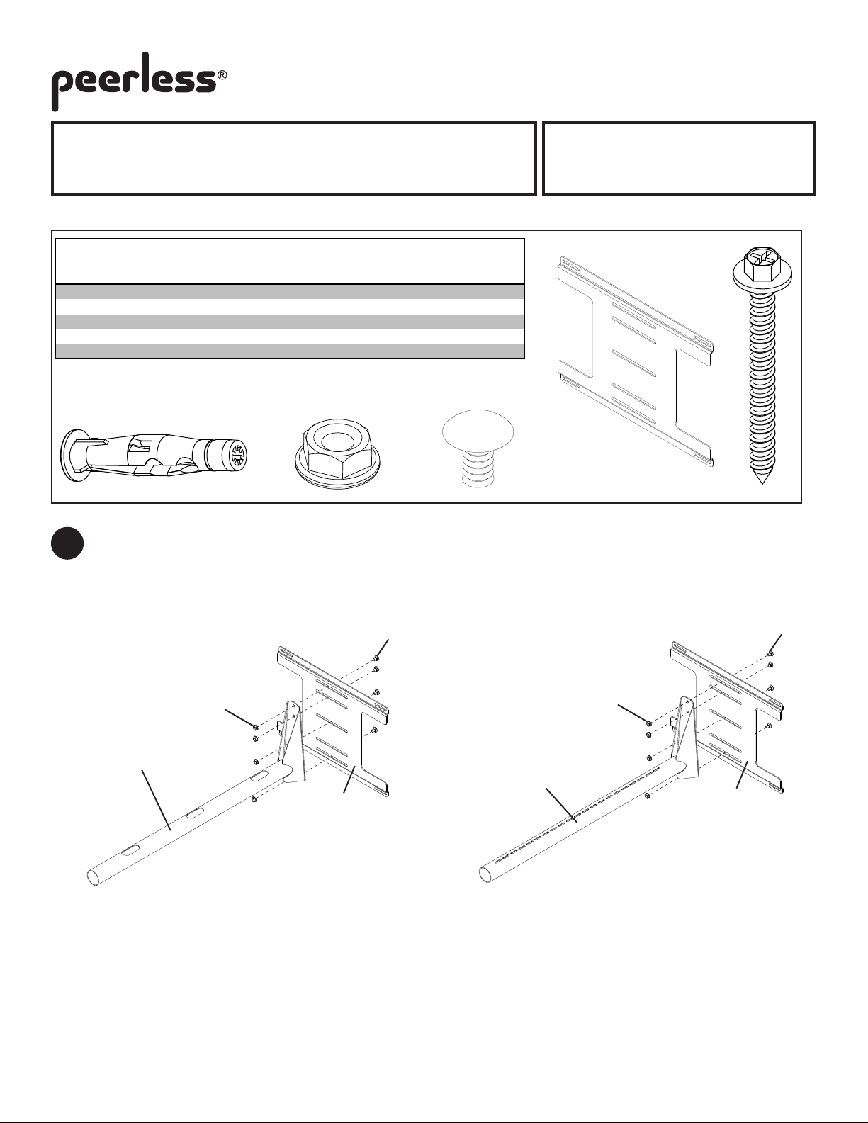
Parts List
Description Qt
wall plate 1
B
#14 x 2.5 phillips hex head wood screw 4
concrete anchor
C
D
lock nut 4
E
carriage bolt 4
WBK-100
. Part # Part #
055-1923 055-2923
5S1-015-C03 5S1-015-C04
4 590-0320 590-0320
530-1016 530-2016
520-9207 520-2047
C
NOTE: Some parts may appear slightly different than illustrated.
Select model of projector wall arm. Secure wall arm (sold separately) to wall plate (A) using four carriage bolts (E)
1
and lock nuts (D).
WBK-100-W
ED
A
B
E
E
D
Sold Separately
A
PSTA-028, PSTA-028-W
PSTK-028, PSTK-028-W
Visit the Peerless Web Site at www.peerlessmounts.com
D
Sold Separately
A
PSTA-2955, PSTA-2955-W
PSTK-2955, PSTK-2955-W
ISSUED: 03-23-09 SHEET #:055-9262-1
Page 2
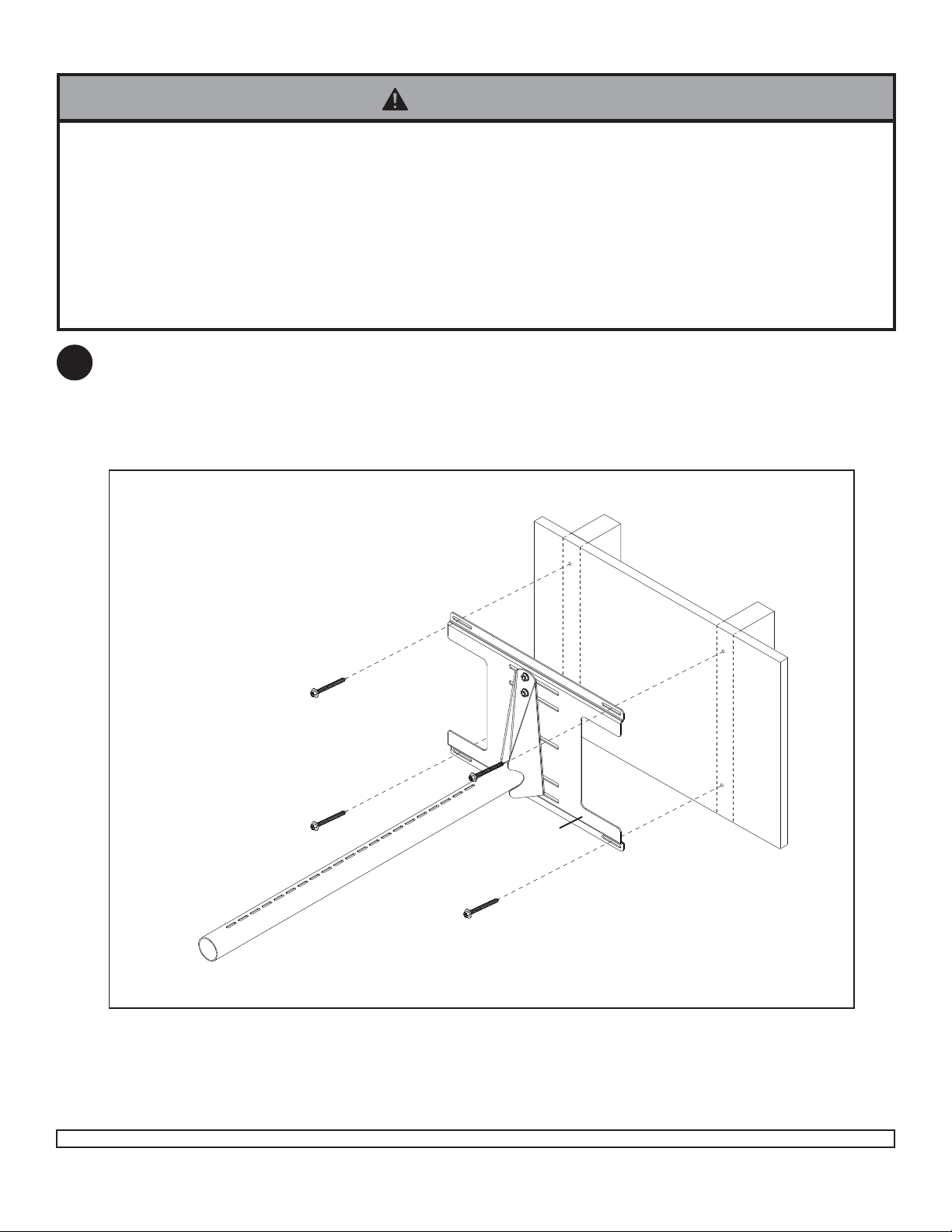
Installation to Wood Stud Walls
WARNING
• Installer must verify that the supporting surface will safely support the combined load of the equipment and all
attached hardware and components.
• Tighten wood screws so that wall plate is firmly attached, but do not overtighten. Overtightening can damage the
screws, greatly reducing their holding power.
• Never tighten in excess of 80 in. • lb (9 N.M.).
• Make sure that mounting screws are anchored into the center of the stud. The use of an "edge to edge" stud finder is
highly recommended.
• Hardware provided is for attachment of mount through standard thickness drywall or plaster into wood studs or joists.
Installers are responsible to provide hardware for other types of mounting situations.
Use a stud finder to locate the edges of the stud. Use of an edge-to-edge stud finder is highly recommended.
2
Based on its edges, draw a vertical line down the stud's center . Place wall plate (A) on wall as a template. Mark
the center of the four mounting holes. Drill four 5/32" (4 mm) dia. holes 2-1/2" (65 mm) deep. Secure wall plate
(A) to wood stud using four #14 x 2-1/2" wood screws (E) as shown. Skip to Step 3 of universal projector wall
arm.
B
A
Visit the Peerless Web Site at www.peerlessmounts.com
2 of 3 ISSUED: 03-23-09 SHEET #:055-9262-1
Page 3

Installation to a concrete or cinder block wall
C
WARNING
• When installing Peerless wall mounts on cinder block, verify that you have a minimum of 1-3/8" of actual concrete surface in the hole to be used for the concrete anchors. Do not drill into mortar joints! Be sure to mount in a
solid part of the block, generally 1" minimum from the side of the block. Cinder block must meet ASTM C-90
specifications. It is suggested that a standard electric drill on slow setting is used to drill the hole instead of a
hammer drill to avoid breaking out the back of the hole when entering a void or cavity .
• Concrete must be 2000 psi density minimum. Lighter density concrete may not hold concrete anchor .
• Make sure that the wall will safely support four times the combined load of the equipment and all attached
hardware and components.
Drill four 1/4" (6 mm) dia. holes to a minimum depth of
3
2.5" (64 mm). Attach wall plate (A) using four concrete
anchors (C) and four #14 x 2 -1/2" wood screws (B) as
shown in Illustration A and 1, 2, and 3. Tighten all
fasteners.
WARNING
• Tighten wood screws firmly, but do not overtighten.
Overtightening can damage the screws, greatly
reducing their holding power.
• Never tighten in excess of 80 in • lb (9 N.M.).
C
B
A
1
concrete
surface
C
Drill holes and insert anchors
2
A
B
Place wall plate over anchors and secure with screws
3
B
Tighten all fasteners.
INCORRECT CORRECT
wall
plate
concrete
wall
plate
C
C
concrete
Illustration A
UTAWAY VIEW
plaster/
dry wall
plaster/
dry wall
WARNING
• Concrete anchors are not intended for attachment to
concrete wall covered with a layer of plaster, drywall,
or other finishing material. If mounting to concrete
wall covered with plaster/drywall is unavoidable,
plaster/drywall (up to 5/8" thick) must be
counterbored as shown right. If plaster/drywall is
thicker than 5/8", custom fasteners must be supplied
by installer .
3 of 3
Visit the Peerless Web Site at www.peerlessmounts.com
ISSUED: 03-23-09 SHEET #:055-9262-1
 Loading...