

Page 1
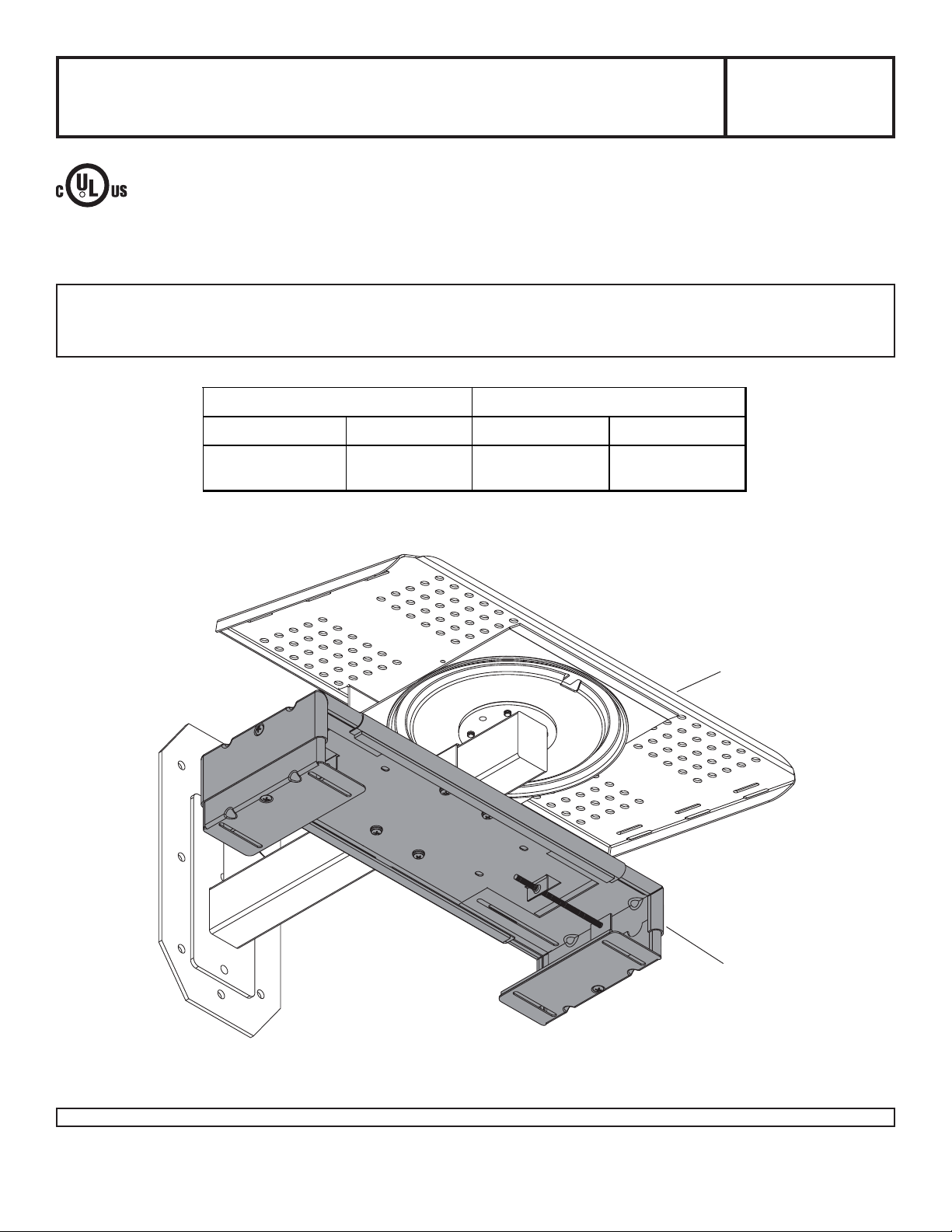
Installation and Assembly -
DVD/DVR/VCR Mount for
Slimline® Standard Wall Mount
Models: VPM 25-W,
SVPM 25-W
This product is intended for use with UL
R
Listed products and must be installed by a
qualified professional installer.
Maximum Load Capacity:
50 lb (22.7 kg)
Read instruction sheet before you start installation and assembly.
Installing a Single DVD/DVR/VCR Mount.......................................................................................................... page 4
Installing Multiple DVD/DVR/VCR Mounts ......................................................................................................... page 5
INSID E DI M ENS IONS MEDI A PLAYER DIMENSI O NS
W IDTH (W) HEIGHT (H) M AXIMUM MI NIMUM
13.25" - 17. 25" 1.5" - 2.75" 17.25" x 2.50" 13.25" x 1.5"
(337 mm - 438 mm) (38 mm - 70 mm ) (438 mm x 64 mm ) (337 mm x 38 mm)
Visit the Peerless Web Site at www.peerlessindustries.com
1 of 5
SLIMLINE WALL MOUNT
DVD/DVR/VCR MOUNT
ISSUED: 05-19-04 SHEET #: 081-9031-2 08-31-04
For customer service call 1-800-729-0307 or 708-865-8870.
Page 2
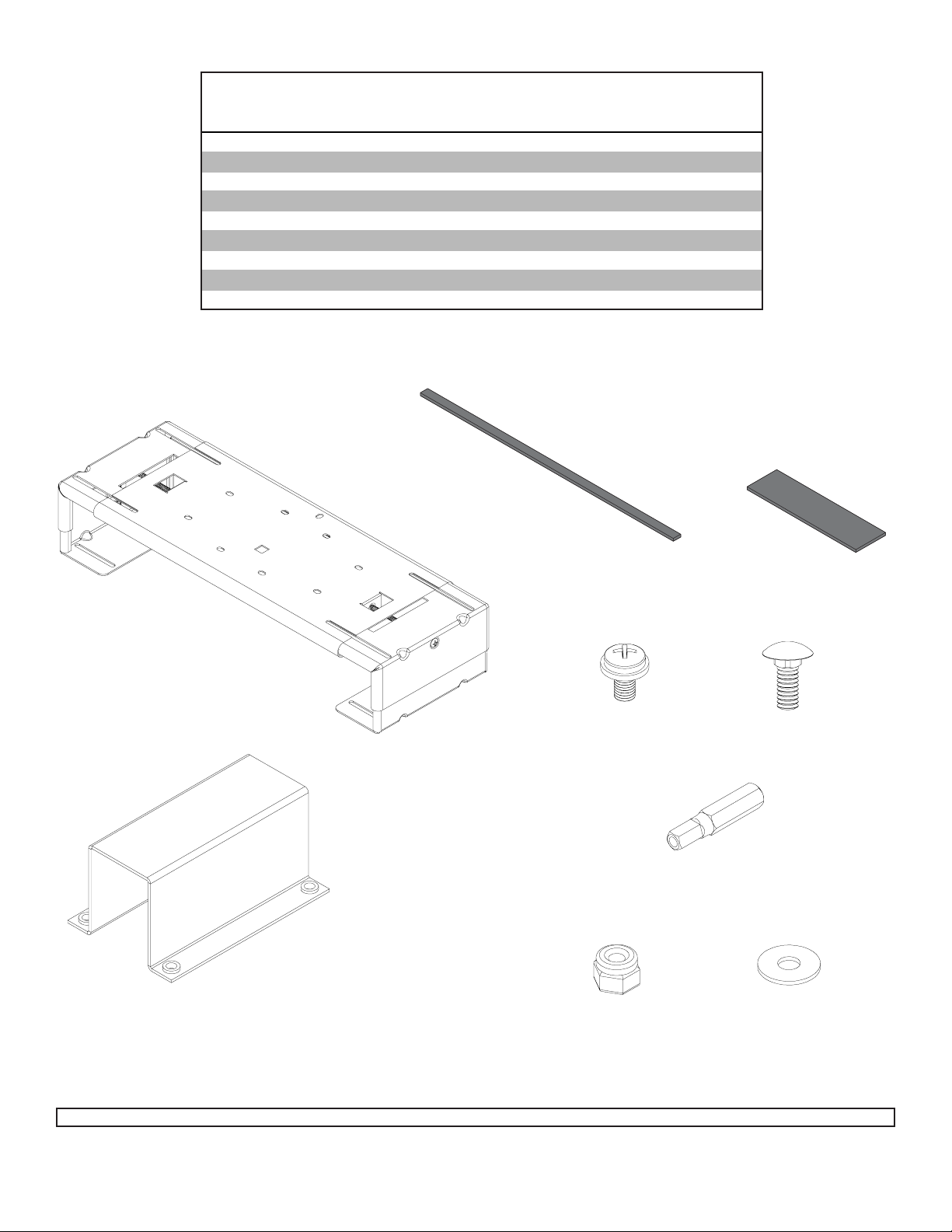
Parts List
Description Qty. Part Part
DVD/DV R/ DVR mou nt 1 081-00 72 081-00 73
A
hanger bracket 1 1245-271 1245-271
B
M5 x .8 x 12 mm phillips sc rew/washer combo 4 520-1030 520-1030
C
#10-24 x 1/2" carriage bolt 4 520-9523 520-9523
D
#10-24 nyloc k nut 4 530-9341 530-9341
E
#10 SAE washer 4 540-9400 540-9400
F
M5 x 1" pent a-pin™ t ool driver 1 – 520-9249
G
1.5" x 4.5" x . 125" adhes i ve foam 2 599-1122 599-1122
H
.375" x 12. 75" x .125" adhes ive foam 2 599-3802 599-3802
I
VPM 25-W SVPM 25-W
I
H
A
B
C
E
D
G
F
Visit the Peerless Web Site at www.peerlessindustries.com
2 of 5
ISSUED: 05-19-04 SHEET #: 081-9031-2 08-31-04
For customer service call 1-800-729-0307 or 708-865-8870.
Page 3

Peel and place four pieces of adhesive foam (H, I) on the horizontal cross support and vertical adjusters as shown
in figure 1.1 and 1.2.
I
VERTICAL ADJUSTER
HORIZONTAL
CROSS
H
SUPPORT
fig 1.1
Slide hanger bracket (B) onto arm, underneath the tray . Att ach DVD/DVR/VCR mount (A) to hanger bracket (B)
using four M5 x 12 mm screw/washer combos (C) as shown below.
SLIMLINE WALL MOUNT
fig 1.2
B
C
Visit the Peerless Web Site at www.peerlessindustries.com
3 of 5
A
ISSUED: 05-19-04 SHEET #: 081-9031-2 08-31-04
For customer service call 1-800-729-0307 or 708-865-8870.
Page 4

Installing a Single DVD/DVR/VCR Mount
Adjust size of DVD/DVR/VCR mount (A) to fit media player by loosening vertical and horizontal adjustment screws
where shown in figure 2.1 on both sides. Insert media player and align front of player with front of TV on Slimline
wall mount. Tighten vertical and horizontal adjustment screws where shown in figure 2.2 on both sides until player
securely fits in mount.
Note: TV and Slimline wall mount not shown in illustrations.
HORIZONTAL ADJUSTMENT SCREW
VERTICAL ADJUSTMENT SCREW
®
A
fig 2.1
MEDIA PLA YER
A
HORIZONTAL ADJUSTMENT SCREW
VERTICAL ADJUSTMENT SCREW
fig 2.2
Visit the Peerless Web Site at www.peerlessindustries.com
4 of 5
ISSUED: 05-19-04 SHEET #: 081-9031-2 08-31-04
For customer service call 1-800-729-0307 or 708-865-8870.
Page 5

Installing Multiple DVD/DVR/VCR Mounts
If adhesive foam (H) is covering slots, trim foam (H) to expose slots. Insert four carriage bolts (D) into
slots of upper DVD mount (A). Loosely attach lower DVD mount (A) using four #10 SAE washers (F)
and #10-24 nylock nuts (E). This will allow access to the vertical adjustment screws of the upper mount
by being able to easily move the lower mount. Note: TV and TV mount not shown in illustrations.
WARNING
• Do not stack more than three DVD/DVR/VCR Mounts
from a TV mount.
WARNING
• Stacked load cannot exceed 50 lb.
VERTICAL
ADJUSTMENT
SCREW
LOWER MOUNT (A)
UPPER MOUNT (A)
H
Adjust size of the upper DVD mount (A) to fit media player by loosening screws on both sides. Insert
media player and align front of player with front of TV on TV mount. Tighten vertical and horizontal
adjustment screws where shown on both sides until player securely fits in mount.
Note: To access the vertical adjustment screws of the upper mount, slide the lower mount to the side.
Repeat for the opposite side.
Center lower DVD mount (A) and securely tighten four nuts (E). Repeat beginning of this step to install
the media player into the lower DVD mount.
D
F
E
DETAIL 1
MEDIA PLA YER
LOWER MOUNT
Visit the Peerless Web Site at www.peerlessindustries.com
© 2004 Peerless Industries, Inc. All rights reserved.
Peerless and Slimline are registered trademarks and Penta-Pin is a trademark of Peerless Industries, Inc.
All other brand and product names are trademarks or registered trademarks of their respective owners.
5 of 5
HORIZONTAL ADJUSTMENT
UPPER MOUNT
VERTICAL ADJUSTMENT
ISSUED: 05-19-04 SHEET #: 081-9031-2 08-31-04
For customer service call 1-800-729-0307 or 708-865-8870.
 Loading...